dale schrage, ms h817 - los alamos national...
TRANSCRIPT


1 LANL2G.doc
Dale Schrage, MS H817Richard LaFave, MS H8175-0029/5-2904LANSCE-1:01-002January 11, [email protected]
SUBJECT: Structural and RF Analysis of LANL 2 Gap, 350 MHzSpoke Resonator Cavity
Introduction:
As requested, a combined structural and RF analysis of the LANL 2-gap, 350MHz spoke resonator has been performed. This memo summarizes the modelpredictions for maximum end flange deflections and reaction forces during tuning, cavitystress and deflections under vacuum loads, and resonant structural frequencies. Inaddition, predictions for shifts in resonant RF frequency are presented. The resultsshown in Tables 1 through 4 summarize the model predictions for the various conditionsconsidered. Material properties are listed in Table 5.
Models:
Figures 1, 2a, and 2b show external and a section views of the cavity. Figures 3aand 3b show the section views along with some dimensions to indicate the overall sizeof the cavity. Although Figure 3a shows the annular stiffener diameter as 26 cm, 24 and28 cm diameters were also considered. Four models of the spoke resonator have beenconstructed for MICAV and COSMOS/M. The first is a solid model of the RF volume thatis used to predict RF resonant frequencies, while the three remaining models are shellmodels of the cavity structure with the various annular stiffener diameters mentionedpreviously. The structural models were constructed such that the resulting nodaldisplacements could be imposed directly on the RF volume model, resulting in resonantRF frequency shift predictions for the deformed geometries. Figures 4 and 5 show themesh used in the RF volume model while Figures 6 and 7 show the structural mesh forthe 26 cm diameter annular stiffener model. Material properties were taken as theambient temperature niobium properties listed in Table 3 of LA-UR # 99-5826 and arereproduced in Table 4.
The RF model was meshed with four node tetrahedral elements resulting inproblems with approximately 60,000 elements while the structural models were meshedwith three node shell elements resulting in problems with approximately 10,000elements.
Boundary Conditions:
Two sets of boundary conditions were imposed on each of the three structuralmodels to simulate two methods of tuning the cavities. In the first the annular stiffenersare fully constrained while a fixed deflection is imposed on each of the bore tube end
Los AlamosN A T I O N A L L A B O R A T O R Y
Tech-memoLANSCE DivisionGroup LANSCE-1
To/MS:
From/MS:
Phone/FAX:
Symbol:
Date:
Email:
2 LANL2G.doc
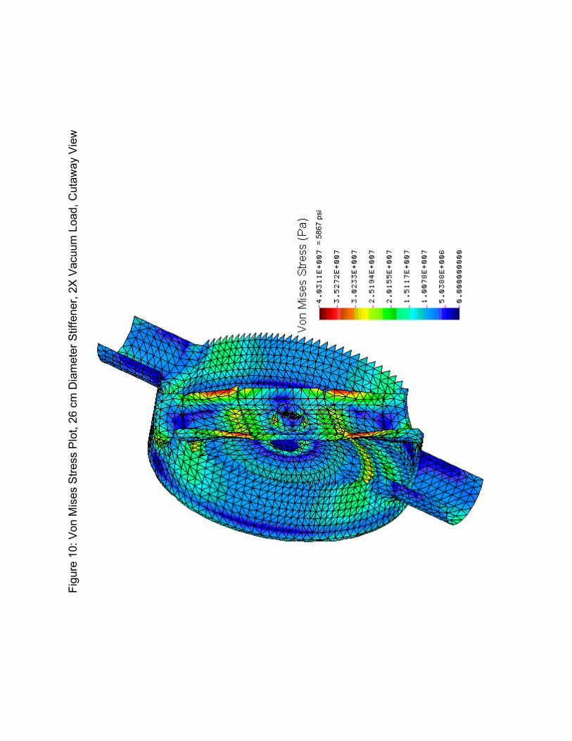
flanges. In the second the fixed deflection is imposed on both the annular stiffeners andthe bore tube end flanges. The amount of the fixed displacement was varied until theresulting peak stress reached the level specified in Table 1 of 7000 psi, correspondingto the yield point of room temperature niobium. Since the model was linear this trial anderror procedure was trivial.
The cavities were also analyzed under vacuum loading conditions. In thesecases both bore tube end flanges and both annular stiffeners were fully constrained while2X atmospheric pressure (29.4 psi) was applied to all external surfaces.
Lastly the cavities were also analyzed in order to predict resonant structuralfrequencies. In these cases, as with the vacuum loading cases, both bore tube endflanges and both annular stiffeners were fully constrained.
Results and Discussion:
Results for each tuning sensitivity case considered are shown in Table 1. In aneffort to test the MICAV RF predictions, similar simulations were run for the ANL 2-gapcavity for which some experimental results are available. Table 2 summarizes theMICAV predictions for the ANL cavity as well as some of the experimental resultsobtained by Tsuyoshi Tajima, Robert Gentzlinger, and Alan Shapiro. It should be notedthat the MICAV RF predictions show good agreement with available data. This is asignificant benefit since in the past MICAV has only been tested against other computercodes without the benefit of experimental data.
The maximum tuning sensitivity of 46 KHz/mil occurs with the 24 cm diameterannular stiffener although there is not a large difference in the sensitivity between thevarious sizes of stiffeners. As the table indicates, the significant improvement in tuningsensitivity occurs when driving the annular stiffener along with the bore tube end flangeas opposed to fixing the stiffener. Figures 8 and 9 are typical of the stress anddisplacement plots for the case when the stiffener and end flange are driven together.
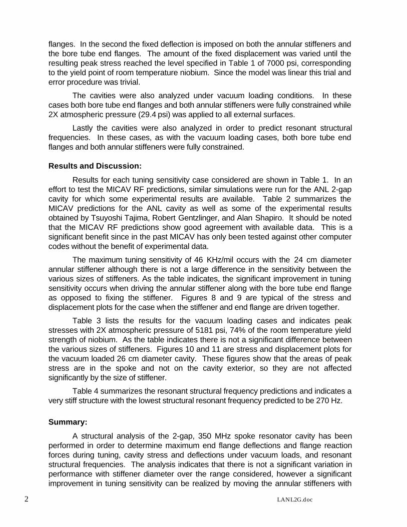
Table 3 lists the results for the vacuum loading cases and indicates peakstresses with 2X atmospheric pressure of 5181 psi, 74% of the room temperature yieldstrength of niobium. As the table indicates there is not a significant difference betweenthe various sizes of stiffeners. Figures 10 and 11 are stress and displacement plots forthe vacuum loaded 26 cm diameter cavity. These figures show that the areas of peakstress are in the spoke and not on the cavity exterior, so they are not affectedsignificantly by the size of stiffener.
Table 4 summarizes the resonant structural frequency predictions and indicates avery stiff structure with the lowest structural resonant frequency predicted to be 270 Hz.
Summary:
A structural analysis of the 2-gap, 350 MHz spoke resonator cavity has beenperformed in order to determine maximum end flange deflections and flange reactionforces during tuning, cavity stress and deflections under vacuum loads, and resonantstructural frequencies. The analysis indicates that there is not a significant variation inperformance with stiffener diameter over the range considered, however a significantimprovement in tuning sensitivity can be realized by moving the annular stiffeners with

3 LANL2G.doc
the bore tube end flanges. This improvement stems from the larger endwall deflectionsthat can be imposed on the structure in this configuration before peak stresses reach7000 psi.

Fig
ure
1: E
xter
nal V
iew
of L
AN
L 2
Gap
Cav
ity -
Sol
idw
orks

Fig
ure
2a: S
ectio
n V
iew
of L
AN
L 2
Gap
Cav
ityF
igur
e 2b
: Sec
tion
Vie
w o
f LA
NL
2 G
ap C
avity

Figu
re 3
a: L
ater
al C
avity
Sec
tion
View
with
Dim
ensi
ons
All D
ims
cm.
Figu
re 3
b: L
engt
hwis
e C
avity
Sec
tion
View
with
Dim
ensi
ons,
All
Dim
s cm
.

Figu
re 4
: RF
Volu
me
Mes
hFi
gure
5: R
F Vo
lum
e M
esh,
Cut
away
Vie
w

Figu
re 6
: Stru
ctur
e Sh
ell M
esh
Figu
re 7
: Stru
ctur
e Sh
ell M
esh,
Cut
away
Vie
w

Figu
re 8
: Von
Mis
es S
tress
Plo
t, 26
cm
Stif
fene
r, St
iffen
er a
nd F
lang
e m
ove
toge
ther
= 70
00 p
si

= 58
67 p
si
Figu
re 1
0: V
on M
ises
Stre
ss P
lot,
26 c
m D
iam
eter
Stif
fene
r, 2X
Vac
uum
Loa
d, C
utaw
ay V
iew

Figu
re 1
1: D
ispl
acem
ent P
lot,
26 c
m D
iam
eter
Stif
fene
r, 2X
Vac
uum
Loa
d, C
utaw
ay V
iew
= .0
0471
in
Annu
lar
Stiff
ener
Tota
lPe
akD
ispl
acem
ent
Dis
plac
emen
tR
FR
FEq
uiv
Stiff
ener
Boun
dary
Rea
ctio
nVo
n M
ises
(Eac
h En
d)(E
ach
End)
Res
onan
tFr
eque
ncy
Tuni
ngTu
ning
Sprin
gD
ia.
Con
ditio
nFo
rce
Stre
ssFr
eque
ncy
Shift
Sens
itivi
tySe
nsiti
vity
Stiff
ness
(cm
)(lb
s)(p
si)
(m)
(in)
(MH
z)(K
Hz)
(KH
z/m
il)(K
Hz/
lb)
(lb/m
il)
28M
oves
With
Fla
nge
1701
7000
0.00
0339
0.01
3335
0.71
4139
-602
.565
-45.
148
-0.3
542
127.
450
28Fi
xed
457
7000
0.00
0140
0.00
5535
1.17
4658
-142
.046
-25.
845
-0.3
108
83.1
5126
Mov
es W
ith F
lang
e16
4970
000.
0003
610.
0142
350.
6712
64-6
45.4
40-4
5.40
4-0
.391
411
6.00
026
Fixe
d40
270
000.
0001
390.
0055
351.
1758
57-1
40.8
47-2
5.66
4-0
.350
473
.248
24M
oves
With
Fla
nge
1662
7000
0.00
0368
0.01
4535
0.64
9922
-666
.782
-46.
076
-0.4
012
114.
847
24Fi
xed
399
7000
0.00
0139
0.00
5535
1.17
7459
-139
.245
-25.
370
-0.3
490
72.6
97
MIC
AVM
easu
red
COSM
OS/M
Erro
rRe
sona
nt Fr
eque
ncy (
MHz
)33
9.69
9401
338.
8214
950.
26%
Tunin
g Se
nsitiv
ity (M
Hz/in
)9.
356
11.3
221
.03%
Stru
ctura
l Stiff
enes
s (lb/
mil)
34.3
644
.429
.22%
(KHz
/lb)
0.27
20.
255
6.35
%
Tabl
e 1:
Stre
ss a
nd D
efle
ctio
n D
urin
g Tu
ning
Unp
ertu
rbed
RF
Res
onan
t Fre
quen
cy =
351
.316
704
MH
z
Tabl
e 2:
AN
L 2
Gap
Cav
ity R
esul
ts


4 LANL2G.doc
CC:K. C. Chan, APT/TPO, MS H816P. Colestock, LANSCE-9, MS H851J. Delayen, JLABR. Garnett, LANSCE-1, MS H817R. Gentzlinger, ESA-DE, MS H821D. Gilpatrick, LANSCE-1, MS H817W. B. Haynes, LANSCE-9, MS H851A. Jason, LANSCE-1, MS H817J. P. Kelley, LANSCE-1, MS H817F. Krawczyk, LANSCE-1, MS H817P. Leslie, LANSCE-1, MS H817M. Lynch, LANSCE-5, MS H818W. Lysenko, LANSCE-1, MS H817M. Madrid, AR/TPO, MS H816T. Myers, Advanced Energy SystemsJ. Rathke, Advanced Energy SystemsB. Rusnak, LLNLD. Rees, LANSCE-5, MS H818E. Schmierer, ESA-DE, MS H821J. D. Schneider, APT/TPO, MS H816S. Schriber, LANSCE-1, MS H817R. Sheffield, APT/TPO, MS H816K. Shepard, ANLH. V. Smith, APT/TPO, MS H816T. Tajima, LANSCE-1, MS H817R. Valdiviez, LANSCE-1, MS H817T. Wangler, LANSCE-1, MS H817R. Wood, LANSCE-1, MS H817K. Zeroonians, SRACLANSCE-1 Reading File, MS H817