dal mardan the forge-welded cannon at … · large iron pillars at delhi 6,7 and dhar 8. therefore,...
TRANSCRIPT

Indian Journal of History of Science, 40.3 (2005) 295-3 19
DAL MARDAN - THE FORGE-WELDED IRON CANNON AT BISHNUPUR
R. BALASURRAMANIAM*, K. BHATTACHARYA*~ AND A.K. NIGAM*
(Received 16 March 2004; revised 27 April 2005)
The forge-welded iron cannon of Bishnupur in West Bengal is addressed in this communication alongwith history and construction meth- odology based on the structural details ofthe cannon. There is no doubt that the cannon was manufactured by forge welding a group of three iron rings over each other and a total of sixty three similar three-ring assemblies were used to produce the thickness of the main barrel of the cannon. The construc- tion and design of the solid portion of the cannon in the rear section has also been discussed. The fracture surface and the entrapped slag inclusions have becn analyzed. The analysis of the rust from the bottom region of the cannon by XRD and FTIR indicated that the major phases were lepidocrocite, goethite, magnetite, 6-FeOOH and phosphates. The absence of diffraction peaks in the XRD from 6-FeOOH and phosphate phases indicated that they might be present in the amorphous form in the rust. The bright reddish-golden appearance ofthe top smooth surface ofthe cannon indicates that the cannon iron rust should be enriched in phosphate, which was confirmed by wet chemi- cal analysis of the rust. The cannon iron must therefore contain a relatively higher percentage of P compared to modem iron. The reason for the beauti- ful colouration of the top surface and for the cannon's excellent atmospheric corrosion resistance may be related to the presence of P in the iron.
Key words: Construction, Design, Forge-welding, Iron cannon, Rust analysis,Wrought iron.
The prominence and development of iron and steel technology in medi- eval India is amply reflected in the manufacture and widespread use of iron and steel'. One of significant large objects manufactured in medieval India was forge welded cannons2. The wonderful forge-welded iron cannons of India from the medieval period have not been documented although there are scattered *Department of Materials and Metallurgical Engineering, Indian Institute of Technology, Kanpur 208 01 6 , INDIA **Department of Metallurgical and Materials Engineering, Indian Institute o f Technology. Kharagpur 72 1 302. INIl1A
296 INDIAN JOURNAL OF HISTORY OF SCIENCE
reports on some of the large cannons present in different parts of India 3-5. Large rnedicval iron cannons are to be found at Murshidabad, Dacca, Bijapur, Gulburga, Thanjavur and Nunvar. It is important to catalogue these forge-welded iron cannons. It must be remembered that ancient Indian were masters is fabri- cating large and small iron objects by forge welding, as amply reflected by the large iron pillars at Delhi 6,7 and Dhar 8 . Therefore, the study of forge welded iron cannons would provide valuable information about the manufacturing meth- odology adopted to manufacture large hollow cylindrical objects by forge weld- ing. Moreover, cataloging provides ideas about the present state and condition of these cannons, apart from enIightening scholars, public and enthusiastic youth about the metallurgical wonders of ancient and medieval India. In the present communication, the large forge-welded iron cannon located at Bishnupur in West Bengal, popularly called as Dalmidul, would be addressed along with its history, structural features and construction methodology. Some metallurgical aspects of the material of construction of the cannon would also be discussed.
A few introductory words on the wrought iron technology of ancient and medieval India will be of interest in this context. Although early dates for the presence and use of iron is available from several megalithic burial sites in south India, its widespread use in India begins from about 800 BC 9. The con- clusion is based on the discovery of numerous iron objects from various ar- chaeological sites from several different parts of India. From the time of its discovery till the middle of 1 Sth century AD, iron has been extracted and pro- cessed into useful shapes by almost the same technology. This extraction meth- odology is termed as the direct process, wherein the iron ore is directly re- duced, in the solid state, to iron in the presence of charcoal. The charge in the ancient iron extraction furnaces, called bloomery hrnaces, was primarily iron ore and charcoal. After the completion of the reduction reaction, the end prod- uct of the bloomery furnace was an iron bloom. The bloom consisted of direct reduced iron particles and the interstices were filled with liquid fayalite slag produced in the extraction process, These hot blooms, immediately after the removal from the furnace, were hammered in order to squeeze out the liquid slag. Some of the liquid slag invariably remained in the material and therefore ancient Indian iron contains entrapped slag inclusions dispersed non-uniformly in the.iron matrix. These slag inclusions essentially contain wiistite, fayalite

THE FORGE-WELDED IRON CANNON AT BISHNUPUR 297
and glassy phases lo. The extracted iron was almost pure without any signifi- cant carbon content because iron was not in contact with charcoal for signifi- cant periods of time in the hrnace. As iron was obtained directly from the ore, it was called the direct process. Iron produced in modem-day blast furnaces contains a large percentage of carbon (i.e., so large that they are essentially cast irons), which has to be further suitably processed in order to reduce the carbon percentage. Therefore, the modern process by which iron (and steel) are ob- tained is called the indirect process. In contrast to modern iron making in the blast furnace, limestone was not charged in the bloomery furnaces and as a result, a higher amount of phosphorus was retained in iron made by the bloomery process. The beneficial effect of phosphorous in iron on atmospheric corrosion resistance in now well understood ". The method of producing iron remained almost unchanged in India over long periods of time in Indian history, till the advent of modern iron-making practices in the late 19+" century 1 2 . The ancient Indian blacksmiths were very adept at utilizing the iron lumps from the bloomery operation, in manufacturing large iron objects by the process of forge-welding, an operation in which lumps of iron are joined together by application of dy- namic force with the lumps in the hot condition. The large iron objects of an- cient and medieval India were all manufactured by forge welding of wrought iron. The Indian blacksmiths were masters in the forge welding technique. It has been rightly criticized that there was sluggishness on the part of medieval Indian blacksmiths to graduate to cast iron technology from bronze casting technology I. The medieval Indian blacksmith was so skillhl in the forging technique that he did not explore casting technologies I . The study of the wrought iron cannon of Bishnupur would help to appreciate the forge-welding technol- ogy in medieval India.
Bishnupur is a small town in Bankura district of West Bengal. The train journey from Kharagpur, a major railway junction, takes about 3 hours. Bishnupur was an important political and cultural center of medieval Bengal, when the Mallas ruled the region called Mallabhumi, consisting of extensive areas of modern Bankura, Midnapore and Bardhaman districts. The region is still reputed for its folk crafts in music, terracotta, metal, silk and cotton weav- ing. It served as the capital of the Mallas. The city was fortified with walls with
298 INDIAN JOURNAL OF HISTORY OF SCIENCE
several prominent gates. Iron cannons were supposed to have been erected on the ramparts of these gates. Armories were located within the fortified city, where iron armories of all kinds were locally manufactured. The detailed his- tory of the Mallas is available in a book published locally by Abhaya Pada Mallik who served in the school at Bishnupur in the early 1900s. This book, History of Bishnupur Raj, was first published in 1921 with a reprinted edition in 1982. A concise history of Bishnupur is available in the publication of Ar- chaeological Survey of India (ASI) 1 3 . Interestingly, the AS1 book while high- lighting the large number of beautiful brick temples, representing all varieties of structural forms of medieval Bengali architecture, does not provide a de- scription of the large wrought iron cannon, but for a fleeting mention. Both the books as Bishnupur record that cannon balls rained from this cannon to push back the Maratha army from its siege of Bishnupur in the 1 7th century. It is clear that the Bishnupur region was famous for iron extraction and iron objects rnanu- facture in the medieval period. This would be also evident in the construction of the iron cannon that will be addressed in the present paper. Local tradition holds than this cannon was fired by God Madan Mohan, the tutelary deity of the Mallas, when Bhaskar Pandit, leading the Maratha army, attacked Bishnupur during the reign of Gopal Singha in early 1 8th century. An interesting tradition is still followed in Bishnupur during the Durga Pooja festival. Some small can- nons from an important temple of Bishnupur are taken in procession to the top of a small hillock, just outside one of the previously imposing gates of the old city, and fired amidst celebrations. This is witnessed by a large number of visi- tors who throng Bishnupur in great numbers during this occasion.
The date of manufacture of the iron cannon is not known with certainty because there is no information regarding its manufacturing date recorded on the cannon. Unfortunately there is no recorded history of the region, from where its origin could be deduced. As the cannon is known to have been used to ward off the attack of the Marathas, the cannon must belong to the period between 1600 and 1700 AD. There are indications, which will be provided later, that the cannon must date to the earliest phase of forge-welded iron cannon manufac- ture in India. It would therefore, be not unreasonable to place the cannon in the 17th century. The fortification of the Bishnupur city was raised by Bir Singh in about 1658 AD and therefore, the Dal Mardan cannon could probably date from this period. Therefore the cannon must be more than 300 years old.

THE FORGE-WELDED IRON CANNON AT BISHNUPUR 299
It was the custom to name medieval cannons with appropriate and in- teresting names, indicative of their power of destruction, for e x ~ p l e , the Jahcinkos'a (Conqueror of the World) cannon at Murshirabad. The original name of the Bishnupur cannon was Dal Mardan - meaning 'Crusher of Group of People'. However, with continued usuage, this original name of the cannon was distorted and nowadays the cannon is referred to simply as Dalmidal. It is currently lying within the Bishnupur town near a lake that is called Lilbiindh. The region around the place where the cannon is located is surrounded by houses. The cannon was lying in a half-buried condition for long time. In 1918, the governor general of Bengal, Lord Ronaldshay, on a visit to Bishnupur, ordered it to be dug out from the ground a d it was then placed on a laterite stone platform. This is the condition in which the cannon appears as of present (Fig. 1). The discoloration of the bottom regions of the cannon is due to the cannon being buried in the ground earlier.
There are two locations on the cannon where an inscription and a mark are to be found. At the rear end of the cannon, on top of the large rim of the cannon, a Persian inscription can be seen (Fig. 2.). This inscription has been interpreted to mean a sum of one lakh and twenty five rupees, indicating possi- bly the cost of the cannon. The notice board put up by the Archaeological Sur-
Fig. 1: The forge welded iron cannon at Bishnupur.

300 INDIAN JOURNAL OF HISTORY OF SCIENCE
vey of India mentions that "the inscription on the body of the cannon suggests that Mohammedan artisans probably manufactured it." The presence of a Per- sian inscription need not necessarily imply that Mohammedan artisans were involved in its manufacture because it is known from the inscribed brass plates on the Jaha'nkos'a cannon that the cannon was constructed in 1637 AD under a chief mechanic called Janiirdhan3. In this regard, Neogi states that "the Dacca, Murshidabad and Bishnupur guns were all manufactured by Hindu mechanics and metallurgists under the orders of the Mohammedan rulers" and the "manu- facture of wrought iron guns must really be regarded as specimens of Hindu artw3. The real meaning of the Persian inscription on the Bishnupur cannon needs to be addressed by learned scholars. The second location where a mark is found is near the front end of the cannon, about one feet from the top on the cannon (Fig. 3). The mark consists of two triangular features placed one on top of another, the lower triangle containing a vertical mark at the bottom while a hooked feature is placed above the higher triangular mark. The significance and meaning of this mark is not understood. It may probably indicate handling instructions for the cannon, or could indicate instructions for charging of gun- powder and cannon ball into the cannon.
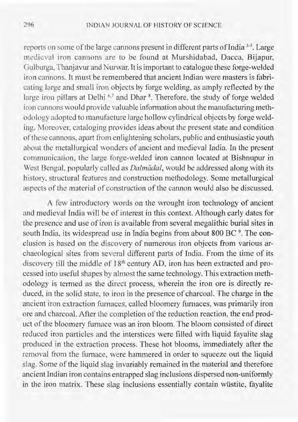
The dimensions of the iron cannon are provided in the engineering draw- ing of Fig. 4. There are two protruding solid cylindrical supports provided half- way along the length of the cannon. These supports must have been used for manipulating the cannon's direction and also for aiding its movement and trans- portation. The total length of the cannon from the front to the extreme rear of the cannon is 3.84 m. The weight of the cannon, estimated based on the dimen- sions, is 7.9 tons. The iron cannon rests on two concrete supports, 25 cms thick and 65 cm high, separated by 2 m from each other. The concrete supporting blocks themselves rest on a raised laterite stone platform.
In addressing the design of the cannon, it can be broadly classed into four different sections, based on the appearance of prominent construction de- tails along the length of the cannon. The section from the front end of the can- non to the raised cylindrical ring (see Fig. 3) would be considered as the first section. The second section can be assumed to be the location from this ring to

THE FORGE-WELDED IRON CANNON AT BTSHNUPUR 30 1
Fig. 2; Persian inscription found in the rear end of the cannon just behind the fubc lock.
Fig. 3: Mark inscribed near the front end of the cannon
302 INDlAN JOURNAL OF HISTORY OF SCIENCE
Oimtnsionr ore in centimetr~ 77mRSLm Oimtnsionr ore in centimetr~
Fig. 4: Engineering drawing of the cannon showing important dimensions.
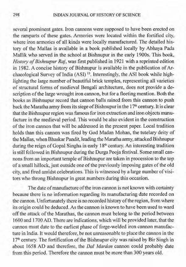
Fig. 5: Front end of the cannon showing that three iron rings have been forged on top of each other successively in order to produce the thickness of the cannon cross section.

THE FORGE-WELDED IRON CANNON AT BISHNUPUR 303
the protruding side supports, the third from the supports to the rear rim while the last section can be assumed to be the rear end of the cannon.
The front section of the cannon (Fig. 5) clearly shows that three forge welding iron rings have been placed one above the other and forged together in order to obtain the gun's thickness. An additional outer iron ring has been pro- vided in the front plane of the cannon and this has been shaped like a triangular cross section in order to provide the aesthetic Iook as well as additional support to the front face of the cannon. The forge welding of the iron rings has been performed in an excellent and skillful manner as can be gauged by the excellent
Fig. 6: Front end of the Thanjavur cannon showing iron strips that have been laid out longitudinally along the length of the inner diameter o f the cannon and folded outwards on the front plane.

3 04 INDIAN JOURNAL OF HISTORY OF SCIENCE
forge welding lines, which in several place on the cannon's front face is almost indistinguishable. Another important feature that is evident in the front plane of the cannon is that there are no supporting iron strips running along the inner diameter of the cannon. This is an important observation. This is quite different from some other forge-welded iron cannons of medieval India, which have been lined with long iron strips, placed longitudinally along their inner diam- eter A good example of the same can be seen in the Thanjavur cannon, whose front end is shown in Fig. 6. The long iron strips have been longitudinally laid out along the inner diameter of the barrel and these strips have been flattened out on the front plane. Comparing this front end with that of DUE Mardank front face, the provision of the inner lining of iron strips must have probably been a later development because this operation is more complicated com- pared to the case without the inner iron strips. The inner iron strips would have ensured higher accuracy for the cannon ball that was fired, due to the smoother surfaces that are realized with the placement of the longitudinal iron strips. The construction of cannons with centrally placed longitudinal iron strips could have also entailed a different manufacturing methodology. It is therefore rea- sonable to propose that the Dal Mardan cannon must be one of the earliest forge welded cannons of medieval India.
The first section of the cannon can be assumed to be up to the first extra strengthening iron ring provided near the front end of the cannon. This occurs at 48 cm from the front end, wherein a raised ring possessing a trapezoidal cross section is seen forged as the extra strengthening ring (Fig. 7). There are eight rings (seen on the outer surface) from the front end to the location of this raised ring. The eight rings, like the other rings that make up the cannon, are not of uniform width but vary between 5 and 7 cm. Of course, it is sometimes difficult to demarcate the exact width of the iron rings because they have been flattened at one edge side in order to close the gaps between them. The forge- welding methodology employed to obtain the same is certainly superior as re- vealed by the excellent maintenance of the overall profile of the cannon. Close observation of the surface of the cannon revealed fine hammer markings all over the surface. There is a noticeable bulge in this section of the cannon with the diameter of the front face tapering down to a smaIler diameter at the strength- ening ring (Fig. 8). Interestingly, from the strengthening ring location onwards

THE FORGE-WELDED IRON CANNON AT BISHNUPUR 305
Fig. 7: Side way view ofthe cannon from the front face up to the extra strengthening ring provided near the front face (section one).
Fig. 8: The taper of the cannon barrel from the front end to the strengthening ring and from the strengthening ring to the rear of the cannon are different.
306 PJDIAN JOURNAL OF HISTORY OF SCIENCE
up to the rear end of the cannon barrel, the cannon barrel exhibits a increasing taper of its diameter (Fig. 8).
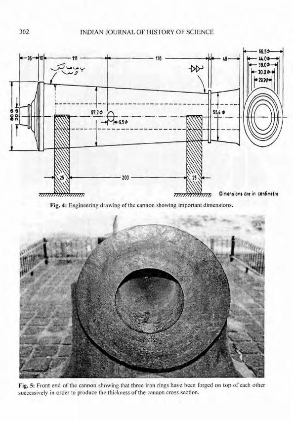
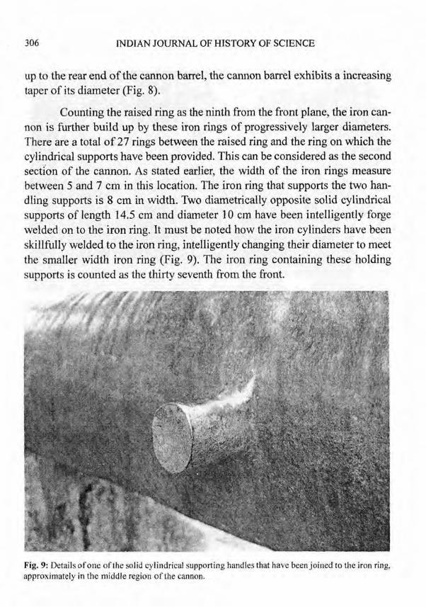
Counting the raised ring as the ninth from the front plane, the iron can- non is further build up by these iron rings of progressively larger diameters. There are a total of 27 rings between the raised ring and the ring on which the cylindrical supports have been provided. This can be considered as the second section of the cannon. As stated earlier, the width of the iron rings measure between 5 and 7 cm in this location. The iron ring that supports the two han- dling supports is 8 cm in width. Two diametrically opposite solid cylindrical supports of length 14.5 cm and diameter 10 cm have been intelligently forge welded on to the iron ring. It must be noted how the iron cylinders have been skillfully welded to the iron ring, intelligently changing their diameter to meet the smaller width iron ring (Fig. 9). The iron ring containing these holding supports is counted as the thirty seventh from the front.
Fig. 9: Details of one of the solid cylindrical supporting handles that have been joined to the iron ring, approximately in the middle region of the cannon.

THE FORGE-WELDED IRON CANNON AT BISHNUPUR 307
The third section can be considered from the iron ring containing the holding supports till the end ofthe tapered cylindrical bore of the cannon. There are a total of 26 iron rings in this section. Interestingly, these iron rings are of slightly smaller width compared to the width of the rings that were placed be- fore the iron ring with the supporting handle. Their thickness ranges between 4 and 6 cm. The opening for lighting the gun powder occurs on the 5th an 6Ih iron ring from the end, at a distance of 19 cm from the rear end of the cylindrical bore. The diameter of the firse hole is 2.5 cm and this is placed in the center of a rectangular depression of dimensions 5 cm x 4 cm (see Fig. 2).
The end supporting (flat) circular piece of iron at the end of the bore is of 7 cm width and therefore, there are a total of 63 iron rings counting from the front to the end of the bore. As it is known from the front face that three rings were shrunk fit over each other to produce the thickness of the gun, a total of 189 iron rings have been used in constructing the tapered cylindrical barrel of the iron cannon. It may be likely that the thickness of the cannon in the rear of the cannon barrel may consist of more than three rings. Careful non-destructive testing using ultrasonic waves would help in understanding the exact thickness and number of forge welded iron rings across the thickness of the cannon at different locations. The iron rings used in the back of the cannon are of pro- gressively larger diameter and smaller width. The diameter of the cannon at different locations has been indicated in the engineering drawing of the cannon in Fig. 4.
The final section of the cannon is the rear end. This is an important location because this section has to withstand the impact to the exploding gun- fire. Its constructional details are worth noting because this would also provide strong clues about the manufacturing methodology of the cannon in the rear section. Two views of the end section are shown in Fig 10(a) & 1 O(b). By introducing a stick into the bore of the cannon, it was found that the total length of the hollow region of the barrel was 3 15 cm. This implies that the hollow region of the cannon extends up to the location where the fuse hole has been provided. Assuming the central portion in the rear region to be made up of a solid cylinder of iron, five assemblies of three rings have been forged on from the fuse hole to the rear plate of the cannon. The rear end (Fig. I Oa) shows that the number of rings has been successively reduced in order to finally reach the

308 INDIAN JOURNAL OF HISTORY OF SCIENCE
solid iron cylinder at the extreme end of the cannon. A reconstruction of the cross section of the rear end is depicted schematically in Fig. 11. This region will also be addressed while discussing the manufacturing methodology of the cannon.
Ideas about the construction methodology of the cannon can be first gleaned fmm the front face of the cannon. The inner rim is 5.6 cm in thickness,
Fig. 10: (a) The rear end section of the cannon side view,

THE FORGE-WELDED IRON CANNON AT BISHNUPUR 309
Fig. 10: (b) The rear end section of the cannon front view.
while the second ring varies between 4.0 cm to 5.4 cm. The outer third ring is about 3 cm in thickness. The fourth ring that is seen on the front face alone measures 6 cm in thickness when the measurements are obtained on the front face, but this is not its actual thickness because it has a triangular cross section (see Fig. 7). This outer fourth ring has clearly been added for strengthening the cannon's front face. The inner diameter of the cannon is 29.1 cm, while the outer diameter is 67 cm. The front end of the cannon, when viewed sideways, exhibits a noticeable bulge in the center (Figs. 5 and 7). Well-shaped hammer marks of relatively smaller diameter are visible both on the inner as well as outer surface of the cannon. The important conclusions that can be drawn from the observation of the front end of the cannon is that three successively larger diameter iron rings have been used to construct the thickness of the cannon. The procedure by which the thickness of the cannon was built up cannot be stated with certainty. There are two possibilities for the manufacture of the main barrel of the wrought iron cannon. The first method would have required shrink fitting of these rings over a central mandrel. The second possible way in which the cannon could have been manufactured is as follows. Biswas de-

310 INDIAN JOURNAL OF HISTORY OF SCIENCE
scribes that during Akbar's (1 556-1 605 AD) time, "the gun barrel was made up of discs of wrought iron through which holes had been punched using ham- mers and chisels. These perforated discs were joined together by forge-welding and the joints were reinforced by cooling these rings contracted tightly on to the joints." Careful observation of the inner surface of the gun barrel did not provide sufficient evidence to conclusively prove which of these two methods was actually used to fabricate the cannon barrel.
The design and manufacture of the cannon in the rear section can be addressed based on the schematic of Fig. 11. A long cylindrical solid iron shaft was first forged and 5 assemblies consisting of three-ringed layers were forged welded over it for obtaining the region near the immediate rear of the fuse box. In case the cannon was manufactured using a mandrel, this must have been in contact with this solid iron shaft in the center and only after the complete manu- facture of the cannon, the central mandrel must have been removed from the front side to provide the hollow bore of the cannon. In case the cannon was constructed of discs of wrought iron that were later punched with holes, these perforated disk assembly must have been joined to the solid part of the cannon beginning from the fuse hoIe region. Returning back to the rear section, careful observation of the details on the rear section (Fig. 10) indicates the bottom of the gun barrel has been constructed of the largest diameter ring, which is also wider than the rings preceding this. Beyond this, proceeding to the back side of the cannon, the third ring (outer ring) has been flattened out. In the next layer, only 2 rings has been shrunk fit with the outer most ring flattened out. Beyond this, only one ring has been provided and this has also been flattened so that the structure seen in the rear of the cannon (Fig. 11) is realized. On carefully ob- serving the type of welding lines on the surface of the cannon rear (Fig. lob), it is noted that these 'rings' on the external face are really composed of individual rectangular pieces of wrought iron, added such that they provide a ring-like appearance. This feature is clearly noticeable in Fig. lob. Additionally, it ap- pears that gaps in the rear section have been intelligently closed by forge weld- ing smaller pieces of iron to cover the gaps. The excellence of forge welding must be appreciated by the observation that the joints have been joined so ex- cellently there were practically no gaps between the forge welded joints on the whole surface. Another observation of significance is that these was no evi-

THE FORGE-WELDED IRON CANNON AT BISHNUPUR 311
dence for the use of lead-based solders between the joints, as observed on the external surface. Their possible use inside the cannon is not known.
Dimensions ore in centimetre
Fig. 11: Schematic cross.section of the rear end of the cannon indicating the possible manufacturing methodology of this section.
After leaving a gap of 2.5 cm, a ring of 2.7 cm width, has been finally shrunk fit over the solid cylinder and this is the final ring that makes up the cannon. The gap created due to this ring and the preceding ring (see Fig. 10a) would have aided lifting and handIing of the cannon, using either ropes or chains. The ingenious construction of the cannon utilizing sound engineering principles has to be appreciated. However, it must be realized that construction of the forge welded cannon must have necessarily been tedious because of the enormous skill (and time) required in precise dimensioning of the various rings. This is important because the rings had to fit tightly over each other once the rings cool down from the high temperature.
In order to obtain a lower-bound estimate of the total number of rings used in constructing the cannon, the ring assemblies in the rear of the cannon must be also taken into account. The largest diameter rear end and the two assemblies behind this are three-ring assemblies ( is . a total of three rings forged over each other like the main body of the cannon). The fourth assembly behind
312 INDIAN JOURNAL OF HISTORY OF SCIENCE
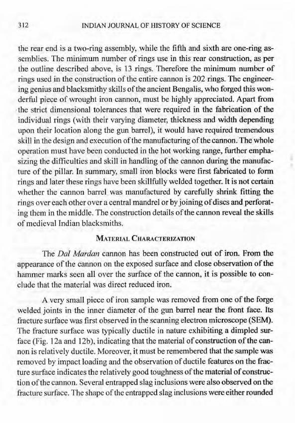
the rear end is a two-ring assembly, while the fifth and sixth are one-ring as- semblies. The minimum number of rings use in this rear construction, as per the outline described above, is 13 rings. Therefore the minimum number of rings used in the construction of the entire cannon is 202 rings. The engineer- ing genius and blacksmithy skills of the ancient Bengalis, who forged this won- derful piece of wrought iron cannon, must be highly appreciated. Apart from
.the strict dimensional tolerances that were required in the fabrication of the individual rings (with their varying diameter, thickness and width depending upon their location along the gun barrel), it would have required tremendous skill in the design and execution of the manufacturing of the cannon. The whole operation must have been conducted in the hot working range, further empha- sizing the difficulties and skill in handling of the cannon during the manufac- ture of the pillar. In summary, small iron blocks were first fabricated to form rings and later these rings have been skillfblly welded together. It is not certain whether the cannon barrel was manufactured by carefully shrink fitting the rings over each other over a central mandrel or by joining of discs and perforat- ing them in the middle. The construction details of the cannon reveal the skills of medieval Indian blacksmiths.
The Dal Mardan cannon has been constructed out of iron. From the appearance of the cannon on the exposed surface and close observation of the hammer marks seen all over the surface of the cannon, it is possible to con- clude that the material was direct reduced iron.
A very small piece of iron sample was removed from one of the forge welded joints in the inner diameter of the gun barrel near the front face. Its fracture surface was first observed in the scanning electron microscope (SEM). The fracture surface was typically ductile in nature exhibiting a dimpled sur- face (Fig. 12a and 12b), indicating that the material of construction of the can- non is relatively ductile. Moreover, it must be remembered that the sample was removed by impact loading and the observation of ductile features on the frac- ture surface indicates the relatively good toughness of the material of construc- tion of the cannon. Several entrapped slag inclusions were also observed on the fracture surface. The shape of the entrapped slag inclusions were either rounded

THE FORGE-WELDED IRON CANNON AT BISHNUPUR 313
or elongated. The elongated nature of the slag inclusions may be due to me- chanical working of the object.
Fig. 12: (a) Fractographs from the sample obtained from the cannon note dimpled fracture surface and
Fig. 12: (b) Fractographs from the sample obtained from the cannon, several entrapped slag inclusions that are spherical in nature can be seen on the fracture surface.
The composition of some of the entrapped inclusions seen on the frac- ture surface was determined utilizing the compositional analysis unit attached with the SEM. The composition of the round shaped slag inclusion, in weight percent, was 34.9 Fe, 23.7 Si, 26.8 Ca, 5.2 Mg, 4.3 K and 5.1 P, while that of the elongated slag inclusion was 44.9 Fe, 1 7.7 Si, 28.6 Ca, 3.2 Mg, 4.3 K and

3 14 INDIAN JOURNAL OF HISTORY OF SCIENCE
1.3 P. Both the different-shaped inclusions were of similar compositions 'and therefore, the elongated nature of the slag inclusion is due to mechanical work- ing. It is noted that the slag inclusions are essentially fayalitic (Fe,SiO,) based on the relatively high amount of Fe and Si detected in the inclusions. It is inter- esting to note the relatively high amount of Ca and Mg in the slag inclusions, which must exist as silicates or phosphates.
The composition of the iron was almost pure iron as indicated by the composition analysis. This implies that the material is wrought iron with very low amount of carbon. Compositional line scans obtained in the SEM across the sample section indicated that the major elements in the material were Fe and P. The content of P was higher at the slag inclusions and this is understand- able based on the results of slag compositions.
As regards the rust nature, some basic observations regarding the col- oration of the surface will be first noted. The cannon exhibits a smooth finish on the top side and this appears bright red in color (see one view of the cannon in Fig. 8). This appearance is typical of phosphoric irons and a good example of the same is seen in the surface of the Delhi and Dhar iron pilIar 7,8. The red colouration of the surface of the cannon also indicates that the material of con- struction of the cannon must have been phosphoric iron. As the color of the cannon in the exposed surface resembles phosphoric iron surfaces, the iron should contain phosphorus in greater amounts compared to modern iron and steel. A major portion of the bottom side of the cannon appears dull in color (see another view of the cannon in Fig. 1) because this portion was buried below the soil before the cannon was removed from the ground and placed in the stand in 191 7. Therefore, the dull coloration of the surface indicates the soil corrosion suffered by the cannon. It is interesting that further exposure of the cannon to the atmospheric environment (from 1917 AD to present) has not changed the color of the previously-buried region to that seen in the top of the cannon. This indicates that prior exposure conditions have an impact on the growing scales on the surfaces of iron in atmospheric corrosion. The surface finish on the side exposed to the environment is smoother than the side that remained buried in the ground. Another conclusion that can be drawn is that the protective film that forms on phosphoric irons will exhibit a beautifid hue when the surface finish is smooth.

THE FORGE-WELDED IRON CANNON AT BISHNUPUR 3 15
In order to obtain fh-ther ideas on the rust nature, sample of rust were obtained from the cannon. It was difficult to remove rust from the top bright surface because the rust thickness was too thin to allow removal of significant amount of rust for analysis purposes. However, there were several regions in the bottom portion of the cannon from where rust could be collected. One such area was the back portion of the cannon. The rust collected from this region was in flaky form, with most of the flakes were of small dimensions. Powdered samples obtained from this rust was subjected to X-ray diffraction experiments and it was determined that the rust was composed primarily of lepidocrocite, goethite and magnetite (Fig. 13). Some peaks, which could not be identified with any iron oxyhydroxide or oxide could be matched with iron phosphate phases, but the identification of the phosphate phase could not be unambigu- ously made. Additionally, a relatively large rust flake obtained fiom the bottom region of the cannon was subjected to rust analysis. XRD patterns were ob- tained fiom the inner side of the flake (i.e. in contact with the metal side) and from the outer side of the flake (i.e. in contact with environment, soil earlier an atmosphere after 191 7). The XRD patterns from the surfaces of the flake were not clearly defined because of the uneven surface of the rust flake. However, the presence of magnetite was confirmed in both the inner and outer sides of the flake. The rust powder was also analyzed by Fourier infiared spectroscopy and it was found that the major phases that were identified were lepidocrocite, goethite, magnetite, 6-FeOOH and phosphate (Fig. 14). The FTIR spectrum (Fig. 14) indicated the presence of magnetite, Fe,-x04, (peak appearing at 572 cm-I), lepidocrocite, y-FeOOH, (peak appearing at 1023 cm-' and its shoulder at 791 cm-I), goethite, a-FeOOH, (peak appearing at 884 cm-') and 6-FeOOH (peak appearing at 465 cm-I). The key absorption bands of these oxides and oxyhydroxides are well known '4,'5. A peak in the FTIR spectrum (Figure 14) corresponding to phosphate ions could be discerned (1030 to 1120 cm-I) indi- cating that ionic phosphates were present in the rust that was studied. The wavenumbers for ionic phosphate is 1030 to 1120 cm-', while for covalent phosphate the band should occur at 920 to 1050 cm-' and for P=O bonds, the spectra occurs at 1200 to 1250 cm-I I6.l7. It is difficult to conclude whether the ionic phosphate, that provided the signal in the spectra, was H,PO, or FePO,. Nevertheless, FTIR spectroscopy proves the existence of phosphates in the can- non rust. The identity of phosphate phases could not be made with certainty in

3 16 INDIAN JOURNAL OF HISTORY OF SCIENCE
Fig. 13: XRD pattern from the rust sample obtained from the bottom surface of the cannon.
0.26 - CI
9 V ., 2 a15 - 2 .- E
L +
I I I I I 1 .P$ H H * a $H fc ; A A .o
I I I I I I I
4000 3500 3000 2 5 0 0 2000 1500 1OOO 500 Wavenumber (ern-')
Fig. 14: FTlR spectrum from the same rust sample used for XRD analysis.

THE FORGE-WELDED IRON CANNON AT BISHNUPUR 317
the XRD analysis and either it could have been in the amorphous forrn, as several phosphates that form on iron are known to be amorphous in nature l 8 or their amount in the rust could have been small. The composition of phosphate ions in two rust samples were determined by chemical analysis methods and it was found out to be 15.3 wt % and 14.7%. Therefore, it appears that the phos- phates present in the rust may be in the amorphous form. It is also interesting to note that no peaks corresponding to 6-FeOOH could be identified in the XRD pattern thereby indicating that it is present in the amorphous state. This amor- phous 6-FeOOH has been called misawite and its contribution to atmospheric corrosion resistance of phosphoric irons have been described elsewhere".
CONCLUS~ONS
The medieval forge-welded iron cannon at Bishnupur has been addressed in this communication. The history of the iron cannon has been briefly pro- vided. The construction methodoIogy of the cannon has been explained based on the structural details of the cannon. Careful and detailed observation of the cannon surface indicates that the cannon has been manufactured by forge weld- ing of three iron rings over each other to produce the thickness of the cannon. Sixty three such three-ring assemblies make up the main barrel of the cannon. The construction and design of the solid portion of the cannon in the rear sec- tion has been described. The skillful forging technology employed to produce this portion of the cannon has been highlighted, and this truly reflects the ge- nius of the medieval Indian blacksmiths that wrought this wonderfbl cannon. The material of construction of the pillar is wrought iron. Analysis of the frac- ture surface indicates that the material is relatively ductile in nature. Both elon- gated and round-shaped slag inclusions were observed in a matrix of almost pure iron. The entrapped slag inclusions have been analyzed for their composi- tion. The analysis of the rust from the bottom region of the cannon by XRD and FTLR indicated that the major phases were lepidocrocite, goethite, magnetite, 5-FeOOH and phosphate. The absence of diffraction peaks in the XRD pat- terns of the 6-FeOOH and phosphate phases indicated that they are present in the amorphous forrn in the rust. The bright reddish-golden appearance of the top smooth surface of the cannon indicates that the cannon iron rust should be enriched in phosphate and this was confirmed by wet chemical analysis. The

318 INDIAN JOURNAL OF HISTORY OF SCIENCE
cannon iron must contain a relatively higher percentage of P compared to mod- em iron. The reason for the wonderful coloration of the top surface and for the cannon's excellent atmospheric corrosion resistance can be related to the pres- ence of P in the iron.
he authors would like to thank the Archaeological Survey of India for their co-operation.
1 . A.K. Biswas, "Minerals and Metals in Medieval India," in History oflndian Science, Technology and Culture, A. D. 1000-1800, ed. A. Rahman, Oxford University Press, New Delhi, 1999, pp. 275-31 3.
2. R. Balasubramaniam, Delhi Iron Pillar - New Insights, Aryan Books International, New Delhi, 2002, pp. 139- 140.
3. P. Neogi, Iron in Ancient India, Indian Association for Cultivation of Science, 191 4, pp. 32-40.
4. K. Roessler, "The Big Cannon Pipe at Tanjawr", Metal News, 19.1 (1997) pp. 1-4.
5. I.A. Khan, Gunpowder and Firearms: Warfare in Medieval India, Oxford University Press, 2004, pp. 17-58.
6 . T.R. Anantharaman, The RusrIess Wonder - A Study of the Iron PiIlar at Delhi, Vigyan Prasar, New Delhi, 1996, pp. 1 1-87.
7. R. Balasubramaniam, "New Insights on the 1600-Year Old Corrosion Resistant Delhi Iron Pillar", Indian Journal ofHistory of Science, 3 6.1 (200 1) 1-49.
8. R. Balasubramaniam , "A New Study of the Dhar Iron Pillar", JJHS, 37.2 (2002) 115-151.
9. V. Tripathi, Iron in South Asia, Aryan Books International, New Delhi, 2001.
10. P. Dillmann and R. Balasubramaniam, "Characterization ofAncient Indian Iron and Entrapped Slag Inclusions using Electron, Photon and Nuclear Microprobes", Bull. Materials Science, 24 (200 1) 3 17-322.
11. R. Balasubramaniam, "On the Corrosion Resistance of the Delhi Iron Pillar", Corrosioh Science, 42 (2000) 2 1 03.
THE FORGE-WELDED IRON CANNON AT BISHNUPUR 319
12. D. Mishra, B. Thakur, S. Chakrabarty and M.K. Lal, "lron Production in India: History, Technology and Development," in Tradition and Innovation in the History of lron Making: An Indo-European Perspective, eds. G. Pande and Jan af Geijerstam, Pahar Parikrama, Nainital, 2002, pp. 294-3 12.
13. S.S. Biswas, Bishnupur, Archaeological Survey of India, New Delhi, 1992, pp. 4-12.
14. T. Misawa, T. Kyuno, W. Suetaka and S. Shimodaira, "The Mechanism ofAtmospheric Rusting and the Effect of Cu and P on the Rust Formation of Low Alloy Steels", Corrosion Science, 1 1 ( 1 97 1) 35-48.
15. T. Misawa, K. Asami, K. Hashimoto and S. Shimodaira, "The Mechanism of Atmospheric Rusting and the Protective Amorphous Rust on Low Alloy Steel", Corrosion Science, 14 (1 974) 279-289.
16. D.A. Skoog and J.J. Leary, Principles of Instrumental Analysis, Fourth Edition, Harcourt Brace College Publishers, New York, 1992, pp. 252-309.
17. R.A. Nyquist and R.A. Kagel, IR Spectra of Inorganic Compounds, Academic Press, New York, 197 1.
18. E.L. Ghali and R.J.A. Potoin, "The Mechanism of Phosphating of Steel", Corrosion Science, 12 (1972) 583-594.