daily localization iii: tomotherapy - american … -4424-4152-656...tumor healthy organ beamlets are...
TRANSCRIPT

Sanford L. Meeks, Ph.DDirector of Physics
Daily Localization III: Tomotherapy

Outline• Physical Characteristics• Quality Assurance• Image Quality• Overview of Clinical Application• System Limitations• Future Developments
– Adaptive Tomotherapy– “Topo”therapy

TomoTherapy HI-ARTIILinac ShownWithout Shielding
Pulse FormingNetwork andModulator
DetectorBeam StopHigh VoltagePower Supply
ControlComputer
Magnetron
Data Acquisition System
Circulator
Gun Board

TomoTherapy
each beamlet can be on/offi.e. temporal modulation
Divides beam into 64 beamletsusing binary mlc

TomoTherapy
Patient
TumorHealthy Organ
Beamlets are turned on or off depending on intersectionwith tumor and healthy organs
Continuously rotating fan beam, with 51 projections per rotation: beam changes every 7 º

1 gantry rotation
Delivery Instructions (Sinogram) for Prostate Delivery

Sinogram
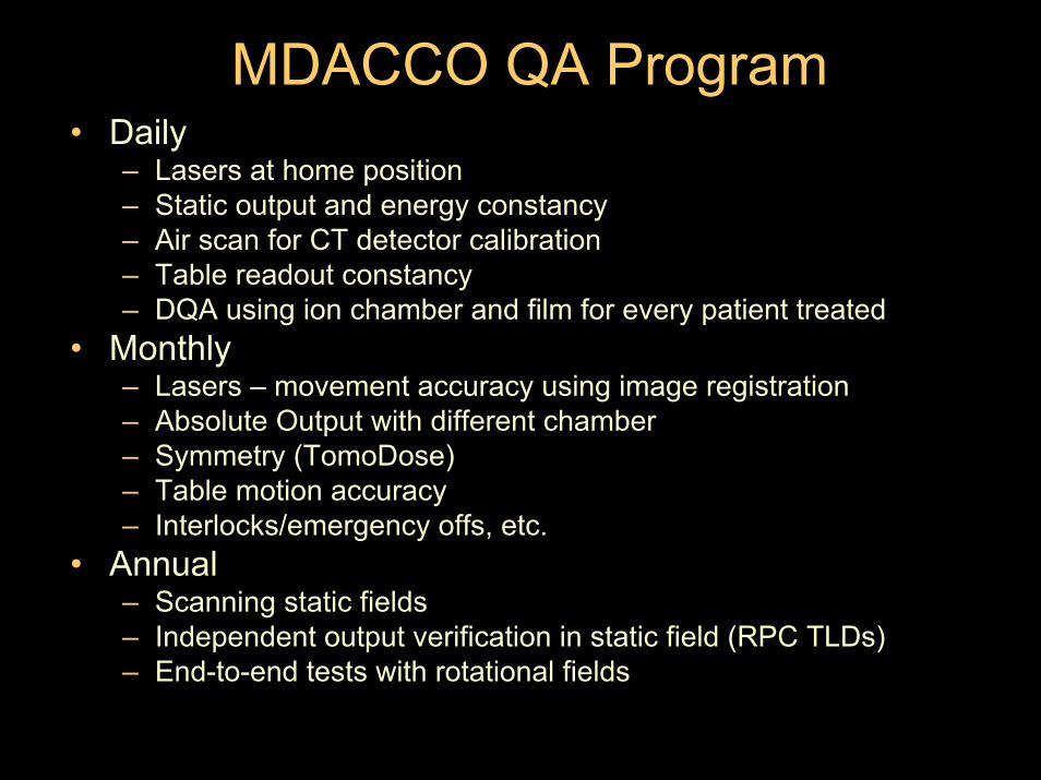
MDACCO QA Program• Daily
– Lasers at home position– Static output and energy constancy– Air scan for CT detector calibration– Table readout constancy– DQA using ion chamber and film for every patient treated
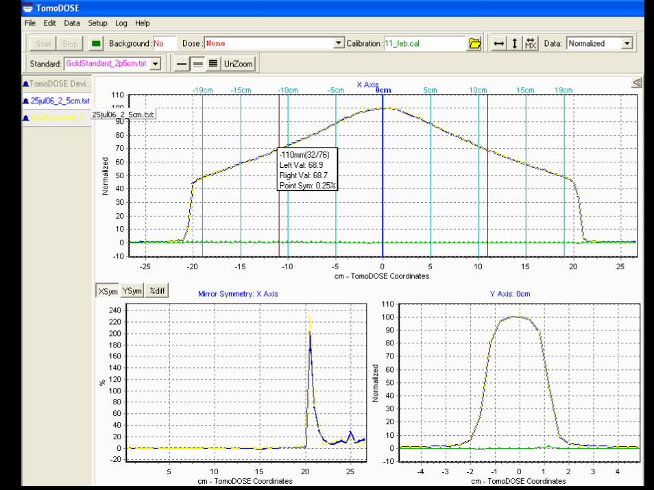
• Monthly– Lasers – movement accuracy using image registration– Absolute Output with different chamber– Symmetry (TomoDose)– Table motion accuracy– Interlocks/emergency offs, etc.
• Annual– Scanning static fields– Independent output verification in static field (RPC TLDs)– End-to-end tests with rotational fields

Compare Scan Data with Model25 by 40 cone
0
10
20
30
40
50
60
70
80
90
100
-300 -200 -100 0 100 200 300
10 cm water10 cm data

Compare Scan Data with Model25 by 40 PDD
0
10
20
30
40
50
60
70
80
90
100
0 50 100 150 200 250
water pddmodel pdd

Langen KM, Meeks SL, Poole DO, et al. Med Phys, 32(11):3424, 2005.

End-to-End Tests2 Gy or 2.5 Gy to the target
50 or 100 cGy to Center Structure
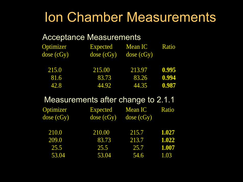
Optimizer Expected Mean IC Ratio dose (cGy) dose (cGy) dose (cGy) 215.0 215.00 213.97 0.995 81.6 83.73 83.26 0.994 42.8 44.92 44.35 0.987
Acceptance Measurements
Measurements after change to 2.1.1Optimizer Expected Mean IC Ratio dose (cGy) dose (cGy) dose (cGy) 210.0 210.00 215.7 1.027 209.0 83.73 213.7 1.022 25.5 25.5 25.7 1.007 53.04 53.04 54.6 1.03
Ion Chamber Measurements

Integrated Quality Assurance
EDR Film
Ion Chamber
TomoTherapy “Cheese”Phantom

DQA – Point Dose MeasurementM. D. Anderson Cancer Center Orlando
TomoTherapyPatient Dose Verification
Patient Name RTOGDate 3/30/2005 15:49Plan Name Plan_03
TomoTherapy Point Dose Verification
Temperature 22.0 0CPressure 755.6 mm HgCTP 1.006Electrometer Inovision 35040Chamber Exradin A1SL, SN 30566Phantom Solid H20 ("Cheese" Phantom)System Calibration Factor (C21) 0.550 [Gy/nC]Ion Chamber Position In Phantom 1 below filmElectrometer Reading for Phantom Irradiation 2.975 [nC]Dosep lan 1.603 [Gy]Dosemeas 1.646 [Gy]Ratio (Dmeas/Dplan) 1.027 Pass


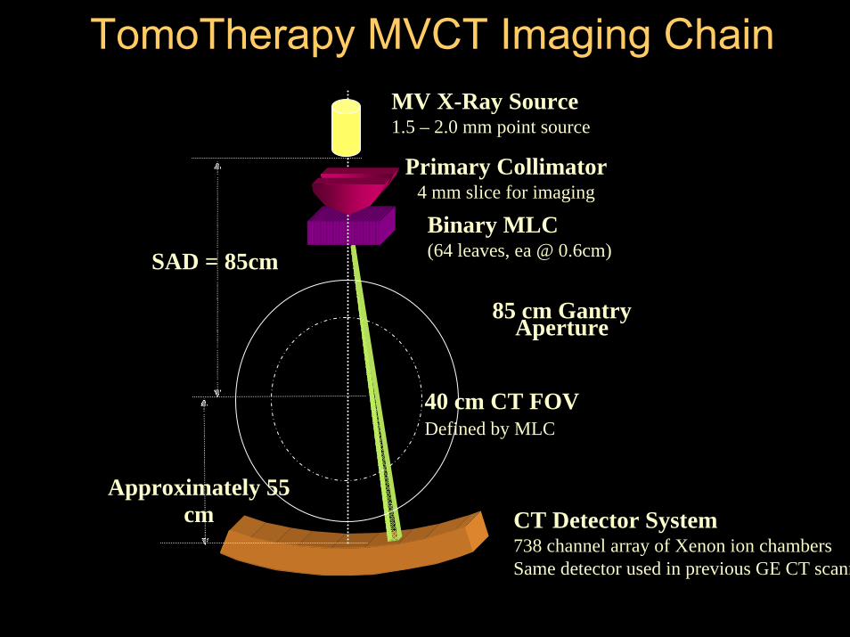
CT Detector System738 channel array of Xenon ion chambersSame detector used in previous GE CT scann
Binary MLC(64 leaves, ea @ 0.6cm)
85 cm Gantry Aperture
40 cm CT FOVDefined by MLC
SAD = 85cm
Approximately 55 cm
MV X-Ray Source1.5 – 2.0 mm point source
Primary Collimator4 mm slice for imaging
TomoTherapy MVCT Imaging Chain

Spatial Resolution Limits
Matrix 0.05 MTF (lp/mm)
NyquistLimit
(lp/mm)
Resolved Diameter
Hole Pattern (mm)
lp/mm Associated with Hole Pattern
Visualization
256 0.105 0.32 >1.75 <0.29
512 0.42 0.64 1.25 0.40
768 0.51 0.96 1.00 0.50
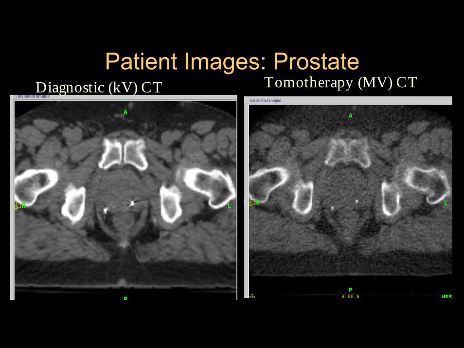
Patient Images: ProstateDiagnostic (kV) CT Tomotherapy (MV) CT

• Uniformity is comparable to diagnostic CT scanners while noise is worse
• MVCT numbers are consistent – suitable for dose calculations
• Spatial resolution using 512x512 matrix is ~1.5 mm • Dose: ~1.1 cGy for 5-mm slice width and pitch of 1; dose
decreases with “looser” pitch• Energy ~ 3.48 MV
– Slightly softer than treatment beam → smaller spot size, improved penumbra & contrast resolution
• Image Quality is acceptable for patient alignment and is also acceptable for delineation of many soft tissue structures.
MVCT Imaging Characteristics
Meeks et al., Med Phys 32(8):2673, 2005

Treatment Planning• No
– beam angles to specify– field sizes to specify – length limit– Energy choices (only 6 MV)
• Available optimization parameters– Jaw setting : 1 – 5 cm (most often 2.5 cm)– Pitch – (p=0.86*1/n) n=1,2,3,4…– Modulation factor – higher means more
modulation– Structure importance– Penalties ( used to drive specific DVH points)

Optimization WindowScreenshot

Tips for Optimization• Optimization is an interactive iterative optimization
requiring user intervention.
• Work first on adequate PTV coverage. This should be achieved in 25-35 iterations. After achieving acceptable dosimetry, increase the penalty of the target structures.
• Next work on one sensitive structure at a time by greatly increasing the penalty of the sensitive structure.

Treatment planning time1. Step: Calculate Beamlets
20 - 30 min for prostate - 1-2 hours for Head and Neckcan be batched, I.e. overnight
2. Step: Optimize plan
0.5 - 1 hour for prostate (30-50 iterations) 1- several hours for Head and Neck (50-several hundred iterations)


MVCT IMAGE
Prostate Helical TomotherapyMutual Information/ Extracted Feature Fusion
KVCT IMAGE

Transverse, aligned

Average In-Room Times
• 5 minutes for setup• 3-5 minutes MVCT scan• 5 minutes reconstruction and
registering MVCT to KVCT and shift patient
• 4-10 minutes beam on time (H&N, prostate)
17-25 minutes total for IGRT and IMRT

System Limitations
• Reliability• Inability to deliver non-coplanar beams• No electrons• Simple treatments no longer simple and
maybe not better– Parallel opposed fields– Tangent breast

System Reliability• 2005 uptime was actually very good (Meeks
calc) = 244/255 days = 96%• TomoTherapy, Inc. Service
– Very responsive– Diagnostic tools are improving– Recent improvements in local parts
inventory/distribution.• Major component reliability still an issue.• Aggravation factor
– System interrupts– Couch

What about “TopoTherapy” as a future solution?Static modulated slit beam with continuous couch translation through beam.
Simple Treatments now hard
Breast tomotherapy Breast topotherapy (opposed tangents)
Gonzalez VJ, Buchholz DJ, Langen KM, et al. Int J RadiatOncol Biol Phys 65(1):284, 2006.

Future DevelopmentAdaptive Tomotherapy
• Daily Image Guidance• Dose Recalculation• Deformable Image Registration• Dose Accumulation• Plan Re-optimization

Use pre-treatment MVCT
Recalculate plan based on planned MLC pattern
Recalculate Dose on MVCT image
Dose Recalculation

- MVCT numbers are reproducible- MVCT to electron density calibration is
reliable- Phantom end-to-end test results are within 1
% of plan results- MVCT images can be used for reliable dose
computations
Langen et al. : Use of megavoltage CT (MVCT) images for dose computations. PMB, 50, pp 4259
MVCT Images for Dose CalculationSummary

DVH Recalculation
Plan DVH
39 “true”DVHs

Original planning CTReference CT
Daily CT Daily CT mappedto Reference CT
Image Deformation

ParotidsDose Shift
Planned Actual
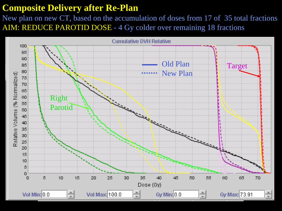
Composite Delivery after Re-PlanNew plan on new CT, based on the accumulation of doses from 17 of 35 total fractionsAIM: REDUCE PAROTID DOSE - 4 Gy colder over remaining 18 fractions
Old PlanNew Plan
RightParotid
Target

35 Plan 117 Del 1 + 18 Del 2
ACTUAL DELIVERED TREATMENT:17 FX PLAN 1 + 18 FX PLAN 2

AcknowledgementsMDACCO• Doug Burch, CMD• Rob Burkavage, CMD• Bobby Chauhan, CMD• Patrick Kupelian, MD• Katja Langen, PhD• Choonik Lee, PhD• Rafael Mañon, MD• Amish Shah, PhD• Robert Staton, PhD• Thomas Wagner, PhD• Twyla Willoughby, MS• Omar Zeidan, PhD
University of Wisconsin/TomoTherapy• Quan Chen, PhD• Rupak Das, PhD• Jason Haimerl, PhD• Weiguo Lu, PhD• Rock Mackie, PhD• Gustavo Olivera, PhD• Ken Ruchala, PhD• Wolfgang Tome, PhD