dai0235c migrating from mips to...
TRANSCRIPT

Application Note 235 Copyright © 2010 ARM Limited. All rights reserved. 1ARM DAI 0235C
Application NoteMigrating from MIPS to ARM
Document number: ARM DAI 0235
Issued: March 2010
Copyright ARM Limited 2010
235

Introduction
2 Copyright © 2010 ARM Limited. All rights reserved. Application Note 235ARM DAI 0235C
Application Note 235Migrating from MIPS to ARM
Copyright © 2010 ARM Limited. All rights reserved.
Release information
The following changes have been made to this Application Note.
Change history
Date Issue Change
May 2010 A First release
June 2010 B Minor corrections
July 2010 C Minor additions
Proprietary notice
Words and logos marked with ® or © are registered trademarks or trademarks owned byARM Limited, except as otherwise stated below in this proprietary notice. Other brandsand names mentioned herein may be the trademarks of their respective owners.
Neither the whole nor any part of the information contained in, or the product described in,this document may be adapted or reproduced in any material form except with the priorwritten permission of the copyright holder.
The product described in this document is subject to continuous developments andimprovements. All particulars of the product and its use contained in this document aregiven by ARM in good faith. However, all warranties implied or expressed, including butnot limited to implied warranties of merchantability, or fitness for purpose, are excluded.
This document is intended only to assist the reader in the use of the product. ARM Limitedshall not be liable for any loss or damage arising from the use of any information in thisdocument, or any error or omission in such information, or any incorrect use of theproduct.
Confidentiality status
This document is Open Access. This document has no restriction on distribution.
Feedback on this Application Note
If you have any comments on this Application Note, please send email [email protected] giving:
the document title
the document number
the page number(s) to which your comments refer
an explanation of your comments.
General suggestions for additions and improvements are also welcome.
ARM web address
http://www.arm.com

Introduction
Application Note 235 Copyright © 2010 ARM Limited. All rights reserved. 3ARM DAI 0235C

Introduction
4 Copyright © 2010 ARM Limited. All rights reserved. Application Note 235ARM DAI 0235C
Table of Contents
1 Introduction ................................................................................................................5
1.1 The ARM architecture .........................................................................................51.2 ARM development tools ......................................................................................51.3 References and Further Reading........................................................................5
2 ARM architecture features.........................................................................................6
2.1 ARM architecture versions ..................................................................................62.2 Programmer’s model...........................................................................................62.3 Debug..................................................................................................................8
3 MIPS and ARM compared..........................................................................................9
3.1 Programmer’s model...........................................................................................93.2 System control and configuration registers .......................................................153.3 Exceptions and interrupts..................................................................................153.4 Memory .............................................................................................................173.5 Debug................................................................................................................193.6 Power management ..........................................................................................203.7 Security features ...............................................................................................21
4 Migrating a software application ............................................................................22
4.1 General considerations .....................................................................................224.2 Tools configuration............................................................................................244.3 Startup...............................................................................................................244.4 Handling interrupts and exceptions...................................................................254.5 Timing and delays .............................................................................................304.6 Power Management ..........................................................................................304.7 C Programming .................................................................................................31

Introduction
Application Note 235 Copyright © 2010 ARM Limited. All rights reserved. 5ARM DAI 0235C
1 Introduction
The purpose of this document is to highlight areas of interest for those involved inmigrating software applications from MIPS to ARM platforms. No attempt is made topromote one architecture over the other, merely to explain clearly the issues involved in adecision to migrate an existing software application from one to the other.
Familiarity with the MIPS architecture is assumed and corresponding ARM features areexplained.
The ARM architecture is supported by a wide range of technology, tools and infrastructureavailable from a large number of partners in the ARM Connected Community. Pointers tothese resources are given where appropriate, although ARM’s own supporting technologyis highlighted.
There is much related documentation available from ARM (see references below) whichshould be consulted where further detail is required.
1.1 The ARM architecture
The ARM architecture represents the most popular 32-bit embedded processor range incurrent use. It is, in essence, a RISC architecture. However, its evolution over the last 24years has introduced many features and extensions which do not necessarily sitcomfortably with the RISC ideal.
The current versions of the architecture are described in more detail below.
1.2 ARM development tools
Tools for developing software for ARM platforms are available from a wide selection ofvendors. ARM itself produces the RealView range of tools for high-performanceapplication development. The Keil Microcontroller Develop Kit (MDK) is a lower-costsolution for development with microcontroller products.
Many other toolsets are available from other vendors, including a free toolchain fromGNU.
1.3 References and Further Reading
ARM Architecture Reference Manual ARMv7-A and ARMv7-R Edition, ARM DDI 0406B
ARMv7-M Architecture Reference Manual, ARM DDI 0403D
Cortex-A9 Technical Reference Manual, ARM DDI 0388E
Cortex-M3 Technical Reference Manual, ARM DDI 0337G
RealView Compilations Tools Developer Guide, ARM DUE 0203I
Keil Embedded Development Tools - Getting Started, ARM KUI 0049A
(All ARM/Keil documentation referenced here may be downloaded directly frominfocenter.arm.com)

ARM architecture features
6 Copyright © 2010 ARM Limited. All rights reserved. Application Note 235ARM DAI 0235C
2 ARM architecture features
ARM is a 32-bit architecture. As such, it has 32-bit registers, ALU, data paths, addressand data buses. Additionally, in the native ARM instruction set, all instructions are 32 bitswide. Individual ARM implementations may have internal 64-bit paths for performancereasons.
2.1 ARM architecture versions
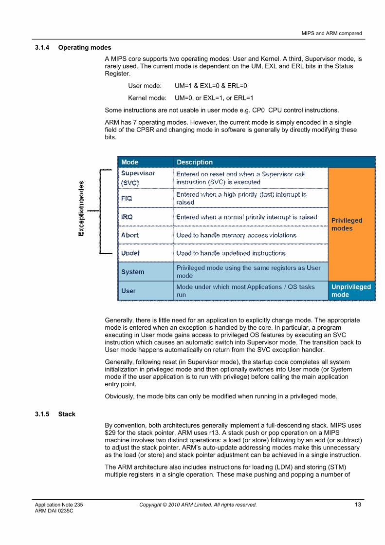
The ARM architecture has been through several revisions since its emergence in the mid1980’s. The most recent version, ARMv7, is implemented in the Cortex range ofprocessor cores. The architecture is defined in three “profiles”, the ‘A’ profile orApplication-class processors, ‘R’ for Real-time and ‘M’ for microcontroller devices.
ARMv7-A is currently implemented in the Cortex-A5, Cortex-A8 and Cortex-A9 processorsand supports fully-featured application class devices capable of running platformOperating Systems such as Linux, WinCE etc. It provides full virtual memory support andoptional media processing extensions.
ARMv7-R is available in the Cortex-R4 and is targeted as applications which require hard,predictable real-time performance. Devices incorporating a Cortex-R4 processor core areused, for instance, in engine management systems, hard disk drive controllers and mobilebaseband processors.
ARMv7-M is used in microcontroller-type devices, principally those based around theCortex-M3 core. This profile supports a subset of features in the v7-A and v7-R profilesaimed at enabling devices which maximize power efficiency and minimize cost. Thearchitecture incorporates many features common in the microcontroller world e.g. bit-banding, hardware interrupt pre-emption etc.
2.2 Programmer’s model
The description presented here is standard for the ARMv7-A and ARMv7-A architectureprofiles. The ARMv7-M microcontroller profile has a different model for modes andexceptions.
2.2.1 Standard features
1. Register set
The ARM register set consists of 37 general-purpose registers, 16 of which are usable atany one time. The subset which is usable is determined by the current operation mode(see below).
In addition to the general purpose registers, the CPSR (Current Program Status Register)hold current status, operating mode, instruction set state, ALU status flags etc.
2. Operating modes
The ARM core supports seven operating modes. All of these, with the exception of Usermode, are privileged. Five modes (Supervisor, Undefined, Abort, FIQ and IRQ) areassociated with handling particular types of exception events. Applications generally runeither in User mode (unprivileged) or System mode (privileged) with the operating system,if one is used, running in Supervisor mode.
3. Instruction sets
Current ARM cores may support several instruction sets:
The native ARM instruction set, in which all instructions are 32-bit.

ARM architecture features
Application Note 235 Copyright © 2010 ARM Limited. All rights reserved. 7ARM DAI 0235C
The Thumb instruction set (introduced in ARMv4T), in which all instructions are16-bit. This provides greatly improved code density.
Java bytecode – cores which include the Jazelle-DBX extension are capable ofexecuting Java bytecode directly in hardware.
The ARM and Thumb instruction sets have both been extended several times sincetheir introduction. In particular, the Thumb-2 extension introduces 32-bit instructionsinto the 16-bit Thumb instruction set providing greatly increased performance withoutcompromising the code density benefits of thumb.
Of the ARM cores available on the market today, all support the ARM and Thumbinstruction sets as a minimum, with the exception of ARMv7-M devices which supportonly the Thumb-2 instruction set.
4. Exceptions and interrupts
ARM supports seven basic exception types. External interrupts are mapped to the FIQand IRQ exceptions. Other exceptions are used for external errors (e.g. bus errors),internal errors (e.g. undefined instructions or memory address translation faults), orsoftware interrupts (caused synchronously by executing an SVC instruction).
5. Memory architecture
ARM cores have a 32-bit address bus providing a flat 4GB linear address space. Memoryis addressed in bytes and may be accessed as 8-byte doublewords, 4-byte words, 2-bytehalfwords or single bytes. Configuration options in the core determine the endianness andalignment behavior of the memory interface.
More advanced ARM cores implement caches, Tightly Coupled Memory (TCM) regions,virtual memory and memory protection features.
2.2.2 Advanced features
1. Neon and floating point
ARM provides a standard floating point coprocessor, VFP, which exists in severalversions. It is capable of both scalar and vector operations in single and double precisionIEEE 754 floating point.
The Cortex-A cores, which implement the ARMv7-A architecture, may include the Neonmedia processing instruction set. If present, this is executed by a separate mediaprocessing engine integrated with the main integer pipeline.
2. Jazelle
ARM provides two optional methods for acceleration of Java and other dynamicallycompiler languages.
Jazelle-DBX (Direct Bytecode eXecution) which supports execution of a subset of Javabytecodes in hardware.
Jazelle-RCT (Runtime Compilation Target) which provides some extended instructionsto improve performance of Just-In-Time compilation techniques forlanguages like Java, Perl etc.
3. Memory protection
Many ARM cores incorporate a Memory Protection Unit (MPU) which allows memory to bepartitioned into a number of regions. Each region cab be assigned access permissionswhich are policed automatically by the MPU at run-time.
4. Virtual memory

ARM architecture features
8 Copyright © 2010 ARM Limited. All rights reserved. Application Note 235ARM DAI 0235C
Application class cores (such as ARM1176JZ-S, Cortex-A9 etc) incorporate a MemoryManagement Unit (MMU). As well as providing the protection capabilities of an MPU, anMMU also provides full virtual-physical address translation allowing implementation ofplatform operating system such as Linux, Windows Mobile etc.
5. Generic interrupt controllers
Almost all ARM-based devices include an interrupt controller of some kind. More recentARM cores have standardized on a Generic Interrupt Controller (GIC).
6. Multicore support
ARM11MPCore and Cortex-A9 MPCore are multi-core versions of the ARM11 andCortex-A9 respectively. They are designed to be used in clusters of up to four cores whichare connected via logic which controls interrupt distribution and manages cachecoherency.
2.3 Debug
ARM provides debug using the industry-standard JTAG port. As standard, this uses a 5-wire connection. A 2-wire version is also available for use in applications where pin-countis at a premium.
ARM’s CoreSight on-chip debug infrastructure allows chip designers to specify and buildcomplex multi-core debug systems which allow synchronous trace and debug of multiplecores within a single device.

MIPS and ARM compared
Application Note 235 Copyright © 2010 ARM Limited. All rights reserved. 9ARM DAI 0235C
3 MIPS and ARM compared
Both MIPS and ARM produce a wide range of processor cores, targeted at various priceand performance points. As far as it is possible to make direct comparisons, the followingtable attempts to line up the product ranges.
MIPS ARM
MIPS4K ARM966E-S and Cortex-M3
MIPS4KEc ARM926EJ-S
MIPS4KSd SC300
MIPS24K ARM1176JZ-S
MIPS24Kc ARM1156T2(F)-S, Cortex-R4
MIPS24Kf ARM1176JZF-S
MIPS34K Cortex-A5, ARM11 MPCore
MIPS74K Cortex-A8, Cortex-A9 UP
MIPS1004K Cortex-A5, ARM11 MPCore
The MIPS64 architecture, supported by MIPS5K and MIPS20K processors incorporates64-bit elements (64-bit data and address paths and a larger virtual memory space, forinstance). ARM processors, since the ARM10 have supported 64-bit data buses betweenthe core and the caches, greatly increasing throughput and efficiency. ARM’s flat 4GBaddress space has been available since the first versions of the architecture.
In this document, where examples are required, we assume that the target ARM core iseither an ARMv7-M device (e.g. Cortex-M3) or ARMv7-A (e.g. Cortex-A9).
3.1 Programmer’s model
Both MIPS and ARM are “RISC” architectures. As such, they have limited instruction setsand large register sets. Both are load-store architectures (i.e. they cannot directlymanipulate the contents of memory locations).
The programmer’s models are therefore somewhat similar since both reflect the RISCapproach. However there are some significant differences.
3.1.1 Register set
Of the two, MIPS has a larger set of general purpose registers, having 32 in all. However,some of these have special purposes and this effectively reduces the set which isroutinely available to the programmer.
The MIPS registers are named $0, $1,…$31. $0 is a pseudo-register which always holdsthe value zero. Several other MIPS registers are reserved for special use in interrupthandlers and also by the assembler for “synthetic” instructions (see below).
The ARM register set is much more straightforward in that all registers, with very fewexceptions, are fully accessible and behave identically. In particular, the program counter(r15, commonly referred to as pc) is generally accessible in the same way as any otherregister. This allows many novel uses of instructions which modify or access the pc tocontrol program flow in efficient ways.
The larger register set offered by MIPS can reduce register pressure for compiled codebut greatly increases the cost of context save/restore operations necessitated by task
MIPS and ARM compared
10 Copyright © 2010 ARM Limited. All rights reserved. Application Note 235ARM DAI 0235C
switches or interrupts. The need to use larger fields in instructions to specify registeroperands also somewhat reduces the flexibility of MIPS instructions. ARM instructions, forinstance, often support more flexible addressing modes as there are bits available toencode more options.
Although the ARM register set is smaller, techniques like register renaming (in whicharchitectural registers are dynamically mapped in the pipeline to a much larger set ofphysical registers) greatly increase the scope for code optimizations in ARM systems.
The MIPs architecture supports the implementation of multiple “shadow” banks ofregisters. This allows more efficient context-switching operations but the fact that thisfeature is not commonly or consistently implemented on MIPS-based devices makes it oflimited use. Consequently, few compilers or operating systems make use of it.
In addition to the general purpose register set, MIPS provides two separate registers (Hiand Lo) to hold the results of a multiply operation. Special instructions are used to readthese registers and copy the contents to general purpose registers. These registers mustalso be saved in the event of exceptions or task switches, increasing the cost of havingthem. In contrast, the ARM multiplication instructions use general purpose registers forinput and output, removing the need to save and restore extra registers.
Both architectures support coprocessors with separate banks of dedicated registers. ARMsupports up to 15 coprocessors (with 11 available for user-definition), while MIPSsupports up to 4.
3.1.2 Status registers
In addition to the general purpose register set, both architectures provide status registersholding e.g. ALU status flags, interrupt status and current mode.
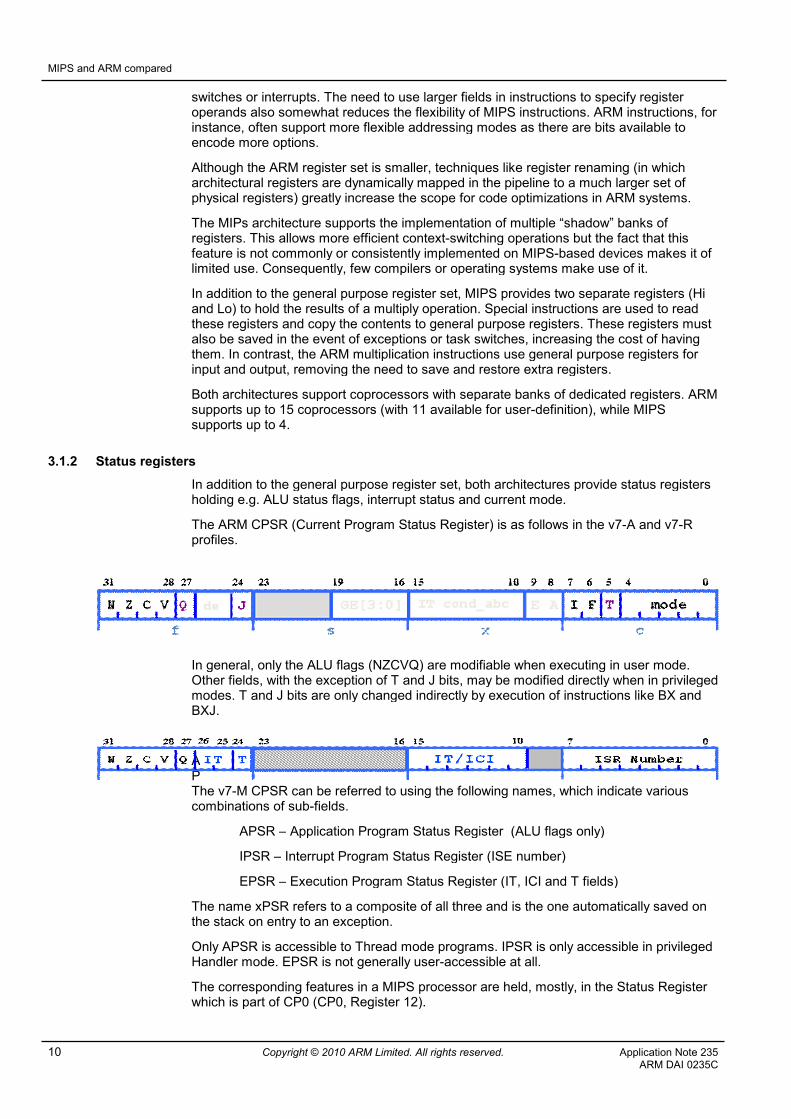
The ARM CPSR (Current Program Status Register) is as follows in the v7-A and v7-Rprofiles.
In general, only the ALU flags (NZCVQ) are modifiable when executing in user mode.Other fields, with the exception of T and J bits, may be modified directly when in privilegedmodes. T and J bits are only changed indirectly by execution of instructions like BX andBXJ.
APThe v7-M CPSR can be referred to using the following names, which indicate variouscombinations of sub-fields.
APSR – Application Program Status Register (ALU flags only)
IPSR – Interrupt Program Status Register (ISE number)
EPSR – Execution Program Status Register (IT, ICI and T fields)
The name xPSR refers to a composite of all three and is the one automatically saved onthe stack on entry to an exception.
Only APSR is accessible to Thread mode programs. IPSR is only accessible in privilegedHandler mode. EPSR is not generally user-accessible at all.
The corresponding features in a MIPS processor are held, mostly, in the Status Registerwhich is part of CP0 (CP0, Register 12).

MIPS and ARM compared
Application Note 235 Copyright © 2010 ARM Limited. All rights reserved. 11ARM DAI 0235C
The following table lists the bits in the MIPS status register and their ARM equivalents.Fields or bits not listed are reserved.
MIPS ARM Location
Name Location Function
CU3-CU0 31:28 CP accesscontrol
CP15CoprocessorAccess ControlRegister
2 bits percoprocesor
RP 27 Reducedpower mode
N/A
RE 25 Reverseendian
CP15 ControlRegister
B, EE
CPSR E
BEV 22 Exceptionvectorlocation
CP15 ControlRegister
V
TS 21 TLBshutdown
N/A
SR 20 Soft Resetindicator
N/A
NMI 19 NMI indicator N/A
IM 15-8 InterruptMask
CPSR I, F
UM 4 User mode CPSR Mode bits
ERL 2 Error Level N/A
EXL 1 ExceptionLevel
N/A
IE 0 InterruptEnable
CPSR I, F
Note that the ALU status flags are not visible in the MIPS status register. They cannot bedirectly modified and can only be tested indirectly via conditional branch instructions. Inthe ARM CPSR, the flags are fully visible and can be read and modified at any time.
3.1.3 Instruction set
In both ARM and MIPS architectures, several versions of the instruction set are defined. Ingeneral, both architectures support backwards compatibility to some degree.
MIPS32 and MIPS64 have been the standard MIPS instruction sets for some years. Bothconsist of 32-bit instructions with MIPS64 (which is backwards compatible) allowing someextended 64-bit addressing modes and a larger virtual address space. MIPS32 was onlystandardized fairly recently.
MIPS supports a number of extensions to the instruction set, termed Application-SpecificExtensions (ASE). The DSP ASE, for example, found in MIPS24K, MIPS34K andMIPS74K cores adds a set of saturating arithmetic and SIMD instructions. This is similar

MIPS and ARM compared
12 Copyright © 2010 ARM Limited. All rights reserved. Application Note 235ARM DAI 0235C
in scope to the instructions added in v5TE of the ARM architecture. However, the fact thatthese extensions are optional means that many applications and tools do not make use ofthem. In contrast, the ARM instruction set is much more standardized and all tools supportthe extensions added at each increment.
Both architectures support floating point operations via an external coprocessor. In thecase of MIPS, this is always CP1, in ARM CP10 is used for single-precision and CP11 fordouble-precision.
The MIPS CorExtend feature allows for user-defined extensions to the core instructionset. However, due to the lack of standardization, this feature is little used. ARM prefers notprovide this kind of ability for licensees, believing that a standardized instruction setmakes for wider tools and operating system support.
ARM and MIPS instruction sets are, as you would expect from two RISC cores, fairlysimilar in many respects. These example pairs of instructions look very similar andperform essentially the same operations.
MIPS ARM
addu $1, $2, $3 ADD r1, r2, r3
lw $3, 20($4) LDR r3, [r4, #20]
jal function BL function
There are some interesting differences.
MIPS has no equivalent to the ARM MOV instruction. ADD to zero or OR withzero are typically used to copy a value from one register to another.
The MIPS ADD instruction generates an exception on overflow and is thereforelittle used. The ADDU instruction, which does not generate an exception, isalmost always used instead – indeed the C compiler will only use this instruction.
All ARM data processing instructions set the ALU condition codes by default.MIPS provides the SLT for comparison between registers (also between a registerand an immediate constant). MIPS branch instructions can only be conditional oncomparison between two registers or between a register and zero.
In contrast, all ARM instructions can be conditionally executed based on a set of14 combinations of the ALU condition codes. MIPS only provides for conditionalbranches. This allows ARM code to be denser and more efficient.
The MIPS instruction set contains explicit shift and rotation operations. In theARM architecture, shift and rotation operations are generally combined with otherdata processing operations (and also with some addressing modes), making useof the inline barrel shifter. This allows for greater throughput and efficiency.
The assemblers for both architectures make extensive use of pseudo instructions toimplement operations which would otherwise be difficult. Examples include the MIPS liand la instructions (for loading an arbitrary 32-bit constant or address). The ARMequivalents are LDR= and ADR.
However, the MIPS assembler makes much greater use of “macros” to synthesize extraoperations which are not part of the native instruction set. An example would be thesequence SLT, BEQ which equates to the ARM BGE instruction. In the MIPS case, theassembler uses a temporary register (almost always $1) to hold the result of thecomparison – this means that this register cannot generally be used by the programmer.
Both architectures provide similar mechanisms for implementing mutual exclusionsemaphores. The MIPS ll/sc pair correspond to the ARM ldrex/strex.
MIPS and ARM compared
Application Note 235 Copyright © 2010 ARM Limited. All rights reserved. 13ARM DAI 0235C
3.1.4 Operating modes
A MIPS core supports two operating modes: User and Kernel. A third, Supervisor mode, israrely used. The current mode is dependent on the UM, EXL and ERL bits in the StatusRegister.
User mode: UM=1 & EXL=0 & ERL=0
Kernel mode: UM=0, or EXL=1, or ERL=1
Some instructions are not usable in user mode e.g. CP0 CPU control instructions.
ARM has 7 operating modes. However, the current mode is simply encoded in a singlefield of the CPSR and changing mode in software is generally by directly modifying thesebits.
Generally, there is little need for an application to explicitly change mode. The appropriatemode is entered when an exception is handled by the core. In particular, a programexecuting in User mode gains access to privileged OS features by executing an SVCinstruction which causes an automatic switch into Supervisor mode. The transition back toUser mode happens automatically on return from the SVC exception handler.
Generally, following reset (in Supervisor mode), the startup code completes all systeminitialization in privileged mode and then optionally switches into User mode (or Systemmode if the user application is to run with privilege) before calling the main applicationentry point.
Obviously, the mode bits can only be modified when running in a privileged mode.
3.1.5 Stack
By convention, both architectures generally implement a full-descending stack. MIPS uses$29 for the stack pointer, ARM uses r13. A stack push or pop operation on a MIPSmachine involves two distinct operations: a load (or store) following by an add (or subtract)to adjust the stack pointer. ARM’s auto-update addressing modes make this unnecessaryas the load (or store) and stack pointer adjustment can be achieved in a single instruction.
The ARM architecture also includes instructions for loading (LDM) and storing (STM)multiple registers in a single operation. These make pushing and popping a number of
MIPS and ARM compared
14 Copyright © 2010 ARM Limited. All rights reserved. Application Note 235ARM DAI 0235C
registers (e.g. on context switch or function entry/exit) much more efficient when workingwith ARM.
Operation MIPS ARM
PUSH single addiu $sp, $sp, -4sw $2, 0($sp)
STR r2, [sp, #-4]!
POP single lw $2, 0($sp)addiu $sp, $sp, 4
LDR r2, [sp], #4
PUSH multiple N/A STMFD sp!, {r0-r3}
POP multiple N/A LDMFD sp!, {r0-r3}
Note that the ARM assembler uses PUSH and POP mnemonics to correspond to theinstruction shown above.
Because of the fundamental inefficiency of MIPS stack operations, MIPS functionsgenerally create a large stack frame in one operation at the head of the function. This isthen used by the function for temporary storage before being deleted on return.
3.1.6 Code execution
Both MIPS and ARM cores employ pipelines to improve instruction throughput. Theeffects of this are exposed in different ways. In general, MIPS exposes pipeline effects ininstruction behavior to a greater extent than ARM. This can make backwards compatibilitydifficult in some cases.
The most obvious difference is that MIPS branch instructions have a “branch shadow”,sometimes called a “branch delay slot”. This means that the instruction immediatelyfollowing a branch instruction is always executed, whether or not the branch itself is taken.In many cases, this feature can be used to some advantage by placing an instruction inthis position in the knowledge that it will be executed before the program reaches theinstruction at the target of a taken branch. However, this is not always possible so it iscommon to see a NOP following a branch instruction.
MIPS assembly programmers need to beware of cases where a single assemblyinstruction can expand into multiple instructions – such instructions cannot be used indelay slots.
Other cases, for instance using the results of a multiply which takes place in parallel withother instructions due to its separate pipeline, are interlocked by the core hardware toavoid any possible hazard.
MIPS processors do, in some cases, require the programmer to take note of “hazards” –instances where the effects of an instruction take time to propagate through and beyondthe core. Subsequent instructions may have to be delayed to wait for this process tocomplete. This applies particularly to CP0 operations on cores which pre-date the 2003revision of the MIPS32/64 architectures. Prior to that revision, it was necessary to insertNOP instructions following an instruction which results in a hazard. A set of hazard barrierinstructions has now been defined in these architectures which can be used to clear anypending hazards.
Similar situations can occur in ARM but much more rarely. Principally, they occur whenchanging the core configuration in such a way that subsequent instructions must be re-fetched, or must wait until data stores have completed. ARM defines a similar set ofbarrier instructions (DMB, DSB and ISB) to cope with these situations.

MIPS and ARM compared
Application Note 235 Copyright © 2010 ARM Limited. All rights reserved. 15ARM DAI 0235C
3.2 System control and configuration registers
Both architectures make use of internal coprocessors for system control andconfiguration.
MIPS uses CP0, ARM uses CP15 (and, to a lesser extent, CP14).
Neither architecture can modify coprocessor registers directly so a read-modify-writestrategy is required. MIPS uses mfc0 and mtc0, ARM uses MRC and MCR. The effect isthe same.
3.3 Exceptions and interrupts
ARM and MIPS have similar exception models in many respects. Both provide minimalhardware support and leave the majority of the actions to software.
Key differences are:
MIPS cores place the return address in EPC; the ARM uses lr for the samepurpose. ARM has an additional register (SPSR) which is used to automaticallysave a copy of CPSR on entry to an exception. MIPS has no equivalent.
Entry to an exception on a MIPS device automatically sets the SR(EXL) bit,placing the core in kernel mode. This has the side-effect of disabling interrupts.
ARM achieves a similar effect by automatically switching into the appropriatemode for the exception type and also setting the A, I and F bits to disableinterrupts.
MIPS cores have a “cause” register which can be read to determine the cause ofthe exception.
ARM cores have a number of such registers – which one to use depends on theexception type e.g. the CP15 Fault Status Register is used to determine the causeof an abort.
Both cores have a dedicated return instruction which restores status and returnsto the interrupted code.
Note though that ARM cores prior to architecture v6 do not support the RFEinstruction and a set of special data processing instructions are used instead.
Both architectures support an external vectored interrupt controller which suppliesindividual handler addresses for all external interrupt sources.
ARM maps several events to the abort exception which are treated separately byMIPS cores. These include TLB miss, MMU address error, external bus error,watchpoint trigger, cache error etc. MIPS cores have no mechanism to generatean abort as a result of a buffered write to memory (this is because MIPS requiresall memory aborts to be precise).
Similarly, several different events in MIPS cores are mapped to the ARM undefexception. These include RI (unrecognized instruction), CpU (coprocessor notenabled), FLE (floating point exception). Both architectures routinely use theseevents as an entry point to soft coprocessor emulation.
The MIPS Syscall exception corresponds to the ARM SVC instruction althoughthe register conventions and instruction format are slightly different.
3.3.1 Interrupt prioritization and pre-emption
Although there are six separate sources for external hardware interrupts, MIPS assumesthat all interrupt prioritization is carried out in software. It is the responsibility of the

MIPS and ARM compared
16 Copyright © 2010 ARM Limited. All rights reserved. Application Note 235ARM DAI 0235C
interrupt handler to carry out any necessary disabling of lower-priority interrupts forinstance.
ARM is similar in this assumption. In general, though, most ARM implementationsincorporate an external interrupt controller which is programmed to carry out this processautomatically, freeing up software to handle the interrupts themselves.
3.3.2 External interrupts
ARM supports two external interrupt sources (some ARMv7-M cores also support anexternal NMI source but this is not universal). They are vectored separately and FIQ has ahigher priority than IRQ. There are some further optimizations to the FIQ mechanismwhich makes it faster than IRQ (extra banked registers, for example). The two can beenabled and disabled separately via the I and F bits in CPSR. There is no global interruptenable flag.
MIPS support six external sources, all of which can be masked separately in the SR(IM)register. There is also a global interrupt mask, SR(IE).
3.3.3 Internal interrupts and exceptions
Both cores support a range of internal exception types. ARM separates our many of theseinto separate vectors in the vector table, making determination of the cause simpler.Almost all MIPS exceptions vector through the same address and the handler will need toexamine the Cause register to determine what happened.
Some major differences:
MIPS treats debug watchpoint triggers as an exception event. ARM handles thesein the debug logic transparently to the programmer.
Some integer arithmetic instructions on MIPS can generate overflow exceptions –a sometimes inconvenient feature. This does not happen on ARM.
TLB translation failures result in an exception in MIPS, requiring softwareintervention to load the correct address translation into the TLB before continuing.ARM cores handle this using dedicated page-table access hardware in the MMUand do not raise an exception when this occurs. See section 3.4.3 below.
3.3.4 Vector table
MIPS exception vectors default to a location in Kseg1 and are relocated automatically toKseg0 once the caches are enabled. The base address of the table can be set using theEBase register but only within Kseg0/1.
ARM’s vector table location defaults to 0x0 but can be relocated to 0xFFFF0000 using theHIVECs feature. This is controlled by a signal which is sensed at reset and subsequentlyvia a software control register. The ARM vector table is in virtual memory space soaccesses to it are always translated via the MMU when enabled – this means that it can,in effect, be located anywhere in physical memory.
MIPS vectors all hardware interrupts to a single handler. The cause register must beinspected by the handler to determine which of the six possible external sources causedthe interrupt.
ARM supports two levels of hardware interrupt (FIQ and IRQ). While they have separatevectors, the vast majority of implementations connect only one source to FIQ and all theothers to IRQ. Because of this, most implementations also include an external interruptcontroller. While these vary, they are usually capable of automatic prioritization andvectoring, thus simplifying software tasks considerably.

MIPS and ARM compared
Application Note 235 Copyright © 2010 ARM Limited. All rights reserved. 17ARM DAI 0235C
3.3.5 Interrupt handlers
Exception handlers are very similar in the two architectures. Both are responsible for anysoftware prioritization, saving and restoring context, interrupt dispatch and return to theinterrupted code.
3.4 Memory
3.4.1 Memory map
The MIPS architecture specifies a fixed memory map. The cache and MMU configurationis partly built into this map. In contrast to ARM, address translation always takes place inthe “mapped” regions and does not depend on whether the MMU is enabled or disabled.ARM devices operate with a “flat” mapping when the MMU is disabled. See the sectionbelow on virtual memory.
In user mode, addresses above 2GB are not permitted and will cause an exception. Usermode programs, therefore, execute entirely within the lower 2GB of the program addressspace. Such accesses are always mapped via the MMU.
The upper half of the address space is divided into 3 (sometimes 4) regions. The regionsbehave differently with respect to virtual memory and the cache but are otherwiseidentical. As can be seen in the diagram, the mapping of the kseg0 and kseg1 regions isfixed and they are mapped to the same physical memory space, the only difference beingthat kseg0 accesses are treated as cacheable.
This tends to force a similar memory map across most applications implemented for MIPSarchitectures. Assuming that an OS is being used and that user mode is being used toenforce some degree of protection:
Kuseg - user processes and data

MIPS and ARM compared
18 Copyright © 2010 ARM Limited. All rights reserved. Application Note 235ARM DAI 0235C
Kseg0 - OS kernel
Kseg1 - reset/initialization code, memory-mapped peripherals
Kseg2 - OS kernel for OS’s which use an MMU
Kseg1 is the only region of memory which is guaranteed to behave usably immediatelyfollowing reset since it is unmapped and uncached. For this reason, the reset vectoraddress lies within it. Following initialization (at least of the caches), many systems willswitch to executing in the Kseg0 region.
3.4.2 Memory protection
MIPS offers memory protection only to the extent described earlier i.e. addresses in theupper 2GB of the address space are not permitted when in user mode. No finer-grainedprotection regime is possible.
ARM offers much more flexible memory protection features, either via a MemoryProtection Unit (MPU) or a Memory Management Unit (MMU). Both allow memory to besplit into a large y number of regions, each having different protection attributes.
Individual memory regions can also have cacheability and bufferability attributes. This kindof configuration is not possible on a MIPS system.
3.4.3 Virtual memory
Both architectures include support for virtual-to-physical address translation, although notall implementations offer it (it is not appropriate, for instance, in microcontroller-typeapplications).
A key difference in terminology is the MIPS term “Program Address” which corresponds tothe ARM “Virtual Address”. The term “Physical Address” has the same meaning in botharchitectures.
The MIPS TLB scheme provides essentially the same features as a Memory ManagementUnit (MMU) in an ARM system but requires much more software support to do so.
In a MIPS system, address translation information is held in the TLB. However, the TLBcannot hold enough translations to cover the requirements of an application or OS of anyuseful size. When a translation is required which is not held in the TLB, the system raisesan exception and the exception handler is responsible for loading the correct translationconfiguration into the TLB before continuing.
An ARM MMU contains dedicated hardware responsible for accessing translation tables inexternal memory automatically when a translation is required which is not stored in theTLB.
From a software point of view. the ARM scheme is much easier to use since it requiresconsiderably less software support. Once the page tables have been constructed, typicallyduring system initialization, they need only be modified on events like context switches.
In both systems, the TLB configuration incorporates extra bits for identifying runningprocesses and reducing the impact of context switches in an operating systemenvironment.
MIPS also supports two other, much simpler, virtual memory architectures terms FixedAddress translation (FAT) and Block Address Translation (BAT). They are not compatiblewith the TLB scheme described above. Details can be found in MIPS documentation.
3.4.4 Access types and endianness
Both cores support both big and little-endian memory systems. In both cases, theselection is via a signal sensed at reset. This setting may be modified in software afterreset.

MIPS and ARM compared
Application Note 235 Copyright © 2010 ARM Limited. All rights reserved. 19ARM DAI 0235C
Both architectures have strict rules governing alignment of data in memory. Essentially,data items must be aligned on natural boundaries. The MIPS assembler supportssynthetic macros to implement unaligned accesses; the ARM assembler has noequivalent.
However, in ARM cores from architecture ARMv6 onwards, these alignment requirementshave been considerably relaxed. In these cores, there is hardware support for access tounaligned data. Note that ARMv6 cores start up in a mode which is backwards compatiblewith earlier behavior and the new features must be explicitly enabled if required.
3.4.5 Caches
Both architectures support similar cache configurations: Harvard L1 caches, backed byoptional unified L2 cache.
MIPS caches have either 4 or 8-word lines, can be 1, 2 or 4-way set associative and areusually write-back. Cacheability of memory regions is part of the fixed address mapdescribed above e.g. Kseg0 is cached, Kseg1 is uncached etc. MIPs allows very little userconfigurability of cacheability beyond this.
MIPs caches are random on reset and need to be manually invalidated before they can beenabled. This varies amongst ARM cores with earlier caches tending to be automaticallyinvalidated and later ones requiring manual invalidation following reset. This process isgenerally more difficult on MIPS cores since the cache maintenance operations work onlywith single cache lines. Many ARM cores provide “global” cache operations which can beused, for instance, to invalidate the entire cache in a single instruction.
In both architectures, the caches are usually virtually-indexed and physically-tagged (onmost ARMv7-A cores, caches are physically-indexed and physically-tagged).
In general, MIPS operations correspond to ARM as shown in the table.
MIPS ARM
Hit Writeback Invalidate Clean and Invalidate
Hit Invalidate Invalidate
Hit Writeback Clean
Fill Preload
3.4.6 On-chip RAM
Both architectures support some kind of dedicated, optimized interface for on-chip SRAM.ARM refers to this as Tightly Coupled Memory (TCM), MIPS as Scratchpad RAM(SPRAM).
In both cases, the memories are optional and the size can be configured by the chipdesigner. Some MIPS devices implement this using one way of the cache, thus reducingthe associativity of the cache.
Once initialized, these memories behave to the programmer much like any other region ofmemory and the implementation differences are not important.
3.5 Debug
Both architectures provide for debug over the standard JTAG connections. The underlyingimplementation, however, is a little different.
MIPS CPUs enter “debug” mode following a debug event (e.g. a breakpoint or single stepinstruction). The core is still running in this state and a resident debug monitor providesdebug functionality to an external host.

MIPS and ARM compared
20 Copyright © 2010 ARM Limited. All rights reserved. Application Note 235ARM DAI 0235C
ARM CPUs support a debug “state” in which the core is halted and isolated from the restof the system. The core can then be controlled from the external system via some on-chiplogic (EmbeddedICE). ARM terms this “halt mode” debugging – ARM chips also supportan alternative, “monitor” mode debugging, in which debug commands are handled by asmall resident monitor. This allows software to be debugged without halting the system.
Both systems support program and data tracing with trace data stored either in on-chipRAM or in an external trace buffer.
To assist with performance benchmarking, both cores incorporate a range of configurablecounters which can be used to capture data in a non-intrusive manner.
3.6 Power management
Devices based on both MIPS and ARM devices support a variety of power-saving modes.In each case, the exact degree of power saving available and the behavior in each powerconfiguration is very dependent on the implementation of the core itself and thesurrounding logic.
MIPS processors provide the SR(RP) bit in the status register. What exactly happenswhen an application sets this bit is entirely system dependent. It may result in lower clockspeed, lower voltage, parts of the chip may be powered down etc. In addition, externalpower controllers may be implemented by the chip designer which will allow theapplication control over various implementation-defined power domains within the device.
ARM devices are more standardized. In general, you will find support for a number ofpower-saving modes, offering progressively greater reductions in power consumption. Ifwe take the Cortex-A9 as an example, the following modes are supported.
Full Run Mode This is the normal mode of operation. The core, memories andsupporting logic are fully powered and running at full clock speed. Whenin Full Run mode, components like Neon or VFP may or may not bepowered. Clearly, they should be powered down when not activelyrequired to minimize unnecessary power use.
WFI/WFE This mode is entered following execution of a WFI or WFE instruction.The majority of the core clocks are stopped, reducing power usage tostatic leakage current only. Since the core is still powered, state isretained fully. The core will return to Full Run mode on an interrupt,debug request, or reset. In the case of WFE mode, assertion of theEVENTI signal will also wake the processor up.
Dormant In Dormant mode, RAMs and caches remain powered while the coreitself is completely shut down and powered off. Prior to entry to thisstate, all core registers must be saved to external memory. Exit is viareset and the reset handler is responsible for restoring the savedregisters and system state.
Shutdown In Shutdown mode, the core, caches and all memories are completelyshutdown. Exit is via reset.
Dormant and Shutdown modes offer the greatest power saving but require an externalpower controller to manage entry and exit. This must be implemented at the time the chipis designed.
The external power controller is also responsible for managing the state of othercomponents on the chip.
Other ARM cores support a similar range of power saving modes.

MIPS and ARM compared
Application Note 235 Copyright © 2010 ARM Limited. All rights reserved. 21ARM DAI 0235C
3.7 Security features
The MIPS 4KSd incorporates some security features aimed at banking and cryptographicapplications. ARM’s SecurCore range provide similar functionality. For further detail onSecurCore, please refer to ARM’s website.

Migrating a software application
22 Copyright © 2010 ARM Limited. All rights reserved. Application Note 235ARM DAI 0235C
4 Migrating a software application
We assume that the majority of software applications are written in a high-level languagesuch as C. It is accepted that small amounts of assembly code will be required to handlethings like reset, initialization, interrupts and exceptions. To a lesser extent, assemblycode may be used to obtain higher performance.
4.1 General considerations
4.1.1 Operating mode
A stand-alone application will most likely execute in a privileged mode at all times in bothsystems - kernel mode on MIPS and supervisor mode on ARM. In this case, no action isrequired as all other mode changes (on ARM, as a result of an exception) will beautomatic.
In an operating system environment, MIPS applications will run in user mode while theoperating system executes in kernel mode. Similarly, ARM applications will execute inuser mode with the operating system in supervisor mode (or possibly system mode insome circumstances). By and large, the mode transitions are also automatic in this case,with supervisor mode on ARM and kernel mode on MIPS being entered automatically onan exception and on execution of a software interrupt (Syscall in MIPS, SVC in ARM). Thetransitions back to user mode will happen automatically on return from the resultingexception.
4.1.2 Stack configuration
Because each mode has its own stack pointer, an ARM core in effect has several stacks.These must each be initialized during system startup following reset, certainly beforeinterrupts are enabled. Stack pointers are generally initialized to reserved areas ofmemory during the initialization sequence.
A MIPS system usually only has one stack, with exceptions saving context to a reservedarea of memory (usually referenced by $26 and $27), so only the system stack requiresinitialization.
4.1.3 Memory map
Unless the system makes use of a particularly complex memory map, the default optionsin the build tools on the target ARM system will normally suffice. If your system has anMMU or MPU and you wish to make use of it, it will need to be configured. If you do notwish to use it, simply leave it alone.
4.1.4 Code and data placement
In general, the ARM memory map is more flexible than that provided by MIPS, particularlyin that it lacks the fixed configuration of cached and mapped areas. This means thatindividual memory devices and individual items of code, data and peripherals may beplaced almost anywhere in the ARM memory map consistent with the layout of physicalmemory devices provided by the chip designer.
1. Code
Operating system code in a MIPS system will usually be placed in kseg0, with user codein kuseg.
The ARM memory map allows code to be placed anywhere where there is suitablememory. Both types of system will benefit, in terms of performance, if code is relocated toRAM during startup. The scatter loading feature of the ARM development tools makes thisrelocation essentially automatic and it is specified completely at build time.

Migrating a software application
Application Note 235 Copyright © 2010 ARM Limited. All rights reserved. 23ARM DAI 0235C
2. Data
In a MIPS system, data is located primarily depending on whether it is to be cached or not.Cached data should be located in kseg0, uncached in kseg1.
In an ARM system, data memory can be placed anywhere, allowing data to be placedaccording to space or performance requirements. The scatter-loading scheme used bythe ARM development tools makes it easy to make the correspondence between initialvalues (held in ROM) and initialized data segments (established and initialized in RAM atstartup).
3. Peripherals
Peripherals in a MIPS system are generally allocated to the uncached and unmappedkseg1 region.
In an ARM system, they can be allocated anywhere outside of any TCM regions. If anMMU or MPU is being used, peripheral regions should be configured as uncached andunbuffered. The scatter control file also allows you very easily to specify that these areasare not initialized automatically during startup (using the UNINIT directive).
4.1.5 Data types and alignment
Type ARM MIPS Notes
char 8-bit signed 8-bit unsigned --unsigned_chars willchange the ARMdefault if required
short 16-bit 16-bit
int 32-bit 32-bit
long 32-bit 32-bit 64-bit in MIPS64
long long 64-bit 64-bit
float 32-bit 32-bit
double 64-bit 64-bit
long double 64-bit 64-bit
Some versions of the gcc compiler for MIPS define long double as a 128-bit type whenusing a MIPS64 device. The MIPS SDE toolkit does not support this.
Code built for MIPS64 devices can also use 64-bit pointers if the 64-bit ABI is selected.
The major difference here when porting code is the sign of the 8-bit char type. Whenporting to ARM, the problem can be ignored if necessary by switching the default usingthe –unsigned_chars compiler switch.
4.1.6 Calling conventions
When interfacing assembler code with high-level languages, it is necessary to conform tothe correct conventions for usage of registers.
For ARM processors, the tools conform to the ARM Executable Application BinaryInterface (EABI). The ARM Architecture Procedure Call Standard (AAPCS) is part of this.Documentation on this can be found on ARM’s website.

Migrating a software application
24 Copyright © 2010 ARM Limited. All rights reserved. Application Note 235ARM DAI 0235C
MIPS has several conventions: N32 (for 32-bit processors) and N64 (for 64-bit) are themost common. Other (O32 for example) are generally obsolete.
The two standards are fairly similar. Each allocates a number of registers for passing thefirst few parameters, with the remainder being placed on the stack. Note though that theway in which MIPS procedures handle the stack is significantly different to ARM. This isprimarily due to the lack of “push” and “pop” type instructions in the MIPS architecture.
MIPS applications, especially those built for Linux, make extensive use of a structurecalled the “Global Offset Table” in order to implement position-independent code anddata. All external references are routed to this global table of pointers which has an entryfor each external symbol. ARM has no need of this and makes use of “literal pools” toachieve the same result.
4.2 Tools configuration
Existing MIPS applications will almost certainly have been developed with the GNUtoolchain or one which incorporates basic tools. There is a range of GNU tools targeted atthe ARM architecture and it would be simplest to migrate to this. For details of thecurrently supported versions of the GNU tools, refer to ARM’s website.
In general, very little of the configuration of the tools will need to change beyond thefollowing.
Memory map, code and data placement
Any options which relate to particular target MIPS architectures, platforms,processors or boards. When deciding on the ARM options, it is good practice tobe as specific as possible with respect to the processor and architecture you areusing.
If your application uses floating point, then you will need to configure carefully foreither hardware floating point or soft emulation.
There is also the option of using the ARM RealView tools. Clearly, more significantreconfiguration will be required here and you should refer to the RealView documentation(all available on ARM’s website) for further information on this.
Any references to MIPS16 will need to be removed. On modern ARM cores, typically allcode is compiled for the Thumb-2 instruction set so no equivalent ARM option is required.
4.3 Startup
The startup sequence for a MIPS application might look something like the following.
1. Start executing from 0xBFC0:0000 (physical 0x1FC0:0000)SR(EXL)=1 (CPU in kernel mode, interrupts disabled)SR(BEV)=1 (exceptions vector through uncached entry points)
2. Branch to main entry point
3. Initialize stack pointer
4. Invalidate caches
5. Invalidate TLB
6. Jump to execute in kseg0 (cached)
7. Set SR(BEV)=0 (switch exceptions to cached entry point)
8. Jump to main application entry point

Migrating a software application
Application Note 235 Copyright © 2010 ARM Limited. All rights reserved. 25ARM DAI 0235C
The equivalent ARM sequence would be as follows.
1. Start executing from 0x0000:0000 (optionally 0xFFFF:0000)I=1, F=0 (interrupts disabled)Supervisor modeARM state
2. Perform ROM/RAM remap if required
3. Enable branch prediction (if supported)
4. Initialize stack pointer
5. Initialize TCMs
6. Invalidate caches
7. Initialize page tables, enable cache & MMU
8. Jump to main application entry point
If porting to an ARMv7-M architecture device (like the Cortex-M3 or Coretx-M4), thestartup sequence can be coded entirely in C (as can exception handlers). This means thatthe MIPS startup sequence can be completely discarded and replaced with an equivalentcoded in C targeted to the ARM device.
4.4 Handling interrupts and exceptions
4.4.1 Writing interrupt handlers
An ARM system usually requires at least two interrupt handlers: IRQ and FIQ.
Typically, a single interrupt source (that with the lowest latency requirement) is connectedto FIQ. FIQ interrupts are not normally nested. At least a simple top-level FIQ handlermust be written in assembler though this will usually call out to a C function to handle theinterrupt before returning, via the assembler, to the interrupted application.
The ARM tools support writing simple (i.e. non-reentrant) IRQ handlers directly in C. Forsimple systems, this is a useful feature. However, most systems require re-entrantinterrupts. This requires a small top-level IRQ handler in assembler which then calls out toa C function to dispatch to the correct handler before return, via the assembler, to theinterrupted application.
The implementation of the assembler part of the handler varies slightly depending on theparticular version of the ARM architecture being used.

Migrating a software application
26 Copyright © 2010 ARM Limited. All rights reserved. Application Note 235ARM DAI 0235C
First we show the code required for v6 and v7 architectures.
Non-nested IRQ handler (v6 and later) Nested IRQ handler (v6 and later)
IRQ_Handler
PUSH {r0-r3, r12, lr}BL identify_and_clear_sourceBL C_irq_handlerPOP {r0-r3, r12, lr}SUBS pc, lr, #4
IRQ_Handler
SUB lr, lr, #4SRSFD sp!, #0x1f
CPS #0x1f
PUSH {r0-r3, r12}
AND r1, sp, #4SUB sp, sp, r1PUSH {r1, lr}
BL identify_and_clear_source
CPSIE i
BL C_irq_handler
CPSID i
POP {r1, lr}ADD sp, sp, r1
POP {r0-r3, r12}RFEFD sp!
The nested IRQ handler re-enables IRQ interrupts (using the CPSIE instruction).However, before doing this, to prevent corruption of the return address, it must change toSystem mode (the first CPS instruction). All registers (including the return address andSPSR) are saved on the System mode stack (this is shared with User mode).
The ARM ABI requires that the stack pointer is doubleword-aligned at public boundariesso exception handlers must check and, if necessary, correct the alignment of the stackprior to making any external function calls.

Migrating a software application
Application Note 235 Copyright © 2010 ARM Limited. All rights reserved. 27ARM DAI 0235C
The code for handling nested interrupts on cores prior to architecture v6 is slightlydifferent as these cores do not support some of the instructions used in the code shownabove (CPS, SRS and RFE).
Non-nested IRQ handler (v5 and earlier) Nested IRQ handler (v5 and earlier)
IRQ_Handler
PUSH {r0-r3, r12, lr}BL identify_and_clear_sourceBL C_irq_handlerPOP {r0-r3, r12, lr}SUBS pc, lr, #4
IRQ_Handler
SUB lr, lr, #4STR lr, [sp, #-4]!MRS r14, SPSRSTMFD sp!, {r0-r4, r12, r14}
BL identify_and_clear_source
MRS r2, CPSRORR r2, r2, #0x1FMSR CPSR_c, r2
AND r1, sp, #4SUB sp, sp, r1STMFD sp!, {r1, lr}BIC r2, r2, #0x80MSR CPSR_c, r2
BL C_irq_handler
MRS r2, CPSRORR r2, r2, #0x80MSR CPSR_c, r2
LDMFD sp!, {r1, lr}ADD sp, sp, r1
BIC r2, r2, #0x1FORR r2, r2, #0x92MSR CPSR_c, r2
LDMFD sp!, {r0-r4, r12, r14}MSR SPSR_csxf, r14LDMFD sp!, {pc}^
Note that this code changes state and enables/disables IRQ by reading and modifying theCPSR directly (this is done via the CPS instruction in later processors).
When porting to an ARMv7-M architecture target, this process is much simpler as the IRQand FIQ handlers can be coded entirely in C as AAPCS-compliant functions. The contextsave and restore operations are carried out automatically by the hardware. Thearchitectural vectored interrupt controller also takes care of prioritisation and dispatch.
4.4.2 Vector table generation
In both architectures, the vector table consists of executable instructions (rather than theaddresses found in many other systems). The MIPS vector table entries are spread out,offering the possibility of writing simple handlers (or, at least, the first part of morecomplex ones) in place in the vector table itself. ARM, having a contiguous list of word-sized entries, offers this possibility only in the case of FIQ. The vector for FIQ is the last inthe table, so the handler for FIQ can be located to start at this address and runcontiguously from that point.
The MIPS table, although spread out over a large memory area, contains fewer entries.This is mainly because all external hardware interrupts vector through a single entry and

Migrating a software application
28 Copyright © 2010 ARM Limited. All rights reserved. Application Note 235ARM DAI 0235C
most other causes (with the exception of cache errors and TLB refills) through one furtherentry. The vector table is usually constructed by explicitly locating exception handlerroutines (often just stubs which call longer handler functions) at the addresses in thevector table.
Address Exception
0xBFC0.0000 - Reset and NMI
0xBFC0.0200 - TLB refill
0xBFC0.0300 - Cache error
0xBFC0.0380 - All others (including interrupts whenCause(IV) is clear)
0xBFC0.0400 - Interrupts (when Cause(IV) is set)
0xBFC0.0480 - Debug exceptions
The ARM vector table consists of a single word-sized entry for each of the eight possibleexceptions.
Address Exception
0x0000.0000 Reset
0x0000.0004 Undefined Instruction
0x0000.0008 Software Interrupt (SVC)
0x0000.000C Prefetch Abort
0x0000.0010 Data Abort
0x0000.0014 (Reserved)
0x0000.0018 IRQ
0x0000.001C FIQ
Each entry in the vector table typically consists of a branch instruction pointing to the startof the relevant exception handler. For a “small” application (i.e. one in which the exceptionhandlers are within direct branch range of the vector table), branch instructions can beused.
Migrating a software application
Application Note 235 Copyright © 2010 ARM Limited. All rights reserved. 29ARM DAI 0235C
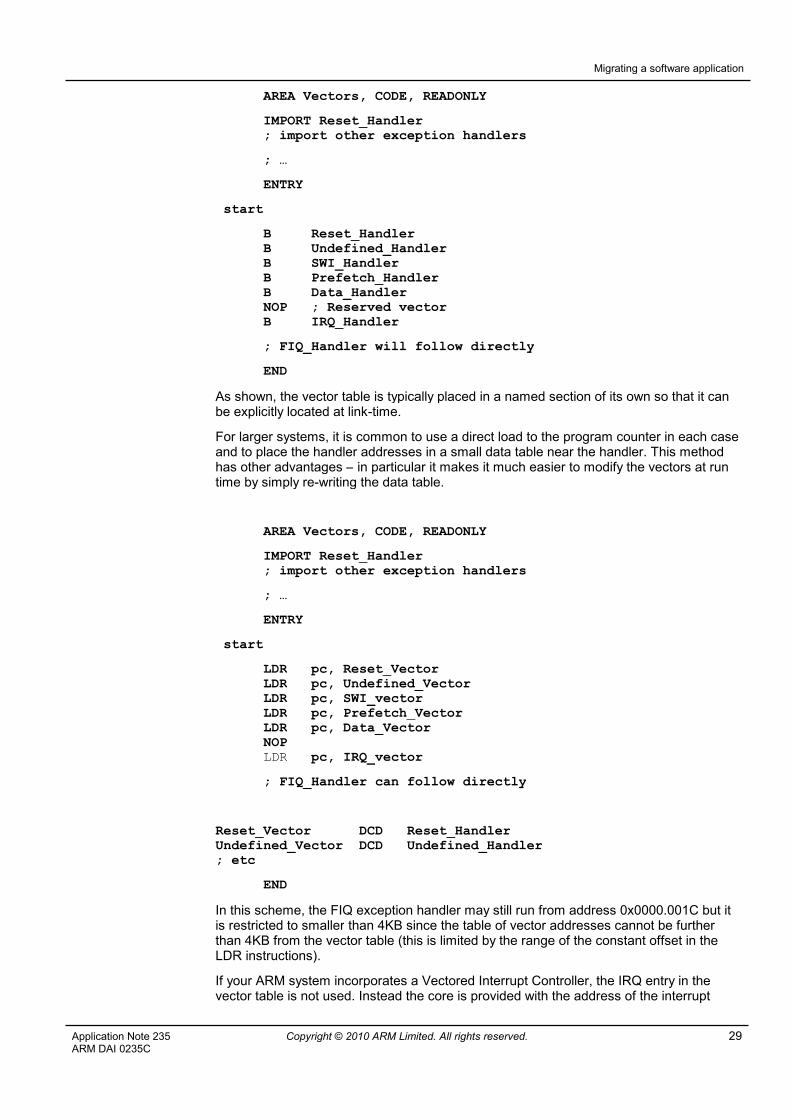
AREA Vectors, CODE, READONLY
IMPORT Reset_Handler; import other exception handlers
; …
ENTRY
start
B Reset_HandlerB Undefined_HandlerB SWI_HandlerB Prefetch_HandlerB Data_HandlerNOP ; Reserved vectorB IRQ_Handler
; FIQ_Handler will follow directly
END
As shown, the vector table is typically placed in a named section of its own so that it canbe explicitly located at link-time.
For larger systems, it is common to use a direct load to the program counter in each caseand to place the handler addresses in a small data table near the handler. This methodhas other advantages – in particular it makes it much easier to modify the vectors at runtime by simply re-writing the data table.
AREA Vectors, CODE, READONLY
IMPORT Reset_Handler; import other exception handlers
; …
ENTRY
start
LDR pc, Reset_VectorLDR pc, Undefined_VectorLDR pc, SWI_vectorLDR pc, Prefetch_VectorLDR pc, Data_VectorNOPLDR pc, IRQ_vector
; FIQ_Handler can follow directly
Reset_Vector DCD Reset_HandlerUndefined_Vector DCD Undefined_Handler; etc
END
In this scheme, the FIQ exception handler may still run from address 0x0000.001C but itis restricted to smaller than 4KB since the table of vector addresses cannot be furtherthan 4KB from the vector table (this is limited by the range of the constant offset in theLDR instructions).
If your ARM system incorporates a Vectored Interrupt Controller, the IRQ entry in thevector table is not used. Instead the core is provided with the address of the interrupt

Migrating a software application
30 Copyright © 2010 ARM Limited. All rights reserved. Application Note 235ARM DAI 0235C
handler for the active interrupt automatically by the interrupt controller and branchesdirectly to that routine. This routine must still be written following the IRQ handlerconventions regarding context saving, register usage, re-entrancy and return instruction.
Later MIPS processors support a vectored exception mechanism in which the vectoraddress is broken out either into eight addresses, one for each of six hardware interruptsources and two for each of two software interrupts (this is Vectored Interrupt Mode) orinto up to 64 separate addresses (this is External Interrupt Controller Mode).
Vectored Interrupt Mode, if available (indicated by Config3(VInt) being set to 1), is enabledby setting the IntCtl(VS) bit.
If an external interrupt controller is available, Config3(VEIC) will be set to 1.
Again, the situation on ARMv7-M devices is much simpler, with a single vector table(which contains addresses) being declared.
4.4.3 Interrupt configuration
Interrupt configuration on a MIPS-based device is largely contained with the Statusregister. This contains the interrupt mask (IM) bits for the individual interrupts, globalinterrupt enable bit (IE), exception level (EXL) and error level (ERL) bits.
An individual interrupt is enabled if:
- Global interrupt enable SR(IE) is set to 1
- Exception level SR(EXL) is clear
- Error level SR(ERL) is clear
- The corresponding mask bit in SR(IM) is set to 1
There may of course be additional configuration required in external peripherals and, ifpresent, an external interrupt controller.
In an ARM system, interrupts (external physical events) and exceptions (internal events)are configured slightly differently. Exceptions (i.e. Undefined Instruction, SVC, PrefetchAbort, Data Abort) are always enabled (though imprecise aborts can be disabled on latercores). IRQ and FIQ must be enabled by clearing the I and F bits respectively in CPSR.Note that these bits work in the opposite sense to the SR(IM) bits in the MIPS Statusregister. Unlike MIPS, the operating mode of the core does not affect the state ofinterrupts – there is nothing corresponding to ERL and EXL.
If an interrupt controller is being used on an ARM system, the configuration will berequired to at least enable and prioritize the external interrupt courses before they can beused.
4.5 Timing and delays
MIPS cores implement a standard counter/timer mechanism using a Count register whichincrements automatically (unless disabled by setting the Status(DC) bit). This can producean output signal from the core. This signal can be connected on-chip back to one of thecore interrupt inputs – traditionally it is multiplexed with interrupt 5.
Of ARM cores, only v7-M architecture devices provide a standard timer function. TheSysTick timer can be clocked either by the core clock or an external clock signal and canbe configured as a single-shot or repeating down counter. A calibration mechanism allowsthe clock to be calibrated during production for exact 10ms timing. On counter expiry, thecounter can generate an exception.
4.6 Power Management
The power management options in an ARM-based device are likely to be more varied, butalso more standardized, than those available with a MIPS device. See section 3.6 above

Migrating a software application
Application Note 235 Copyright © 2010 ARM Limited. All rights reserved. 31ARM DAI 0235C
for a more detailed description of the power management facilities provided by a typicalARM core.
When using an operating system or real-time scheduler, it is likely that the powermanagement features will have been built into the kernel. In this case, it is simply a caseof ensuring that your user processes make it clear to the scheduler when they are idle.How you do this will be system-dependent.
When writing a bare metal application, you will have to insert appropriate instructions intoyour code to allow the hardware to sleep when possible. For instance, busy-wait loopsshould have WFI/WFE instructions inserted. However, it is more power-efficient to avoidpolling in general and implement an interrupt-driven system with power managementinstructions in the main loop.
4.7 C Programming
In general, the similarities between the two architectures will mean that C code which hasbeen optimized for MIPS platforms should perform well when re-compiled for ARM.
Clearly any inline assembler or architecturally-specific intrinsic functions will need to beremoved, replaced or rewritten. Similarly, any cache or TLB maintenance code will needto be rewritten. Recall that TLB management in the two architectures is significantlydifferent: in MIPS systems, address translation depends on run-time support code; inARM systems, the page tables are initialized at startup and the MMU then reads these atrun-time automatically.
Both architectures have similarly strict rules on data alignment. However, ARM coressupporting architecture v6 and later are capable of supporting unaligned accesses inhardware. In Cortex-A cores, this feature is permanently enabled; on earlier cores whichsupport backwards compatibility the feature defaults to disabled and can be enabled, ifrequired, by setting the U bit in CP15 register c1.
Be careful though with any data which has been declared using the packed attribute. Thedeclaration may need to be corrected to use the __packed keyword when using the ARMtools.
In ARM applications, any problems with branch range are fixed up by the linker during thebuild process. Consequently, there is no need to declare functions as “far” or “longcall”.
ARM as no need for any equivalent to the “GP-relative” addressing schemes common inMIPS programs. There is therefore no need to specify an equivalent of the –Gnumcommand line option nor to explicitly declare data in the .small or .comm sections.