d25 manual usuario
TRANSCRIPT

GE Energy
D25 IED User's Manual
994-0081 Version 3.00 Revision 5
General
D25 IED User's Manual GE Energy
2 994-0081-3.00-5 General
COPYRIGHT NOTICE
© 2003-2009, General Electric Company. All rights reserved.
The information contained in this online publication is the exclusive property of General Electric Company, except as otherwise indicated. You may view, copy and print documents and graphics incorporated in this online publication (the “Documents”) subject to the following: (1) the Documents may be used solely for personal, informational, non-commercial purposes; (2) the Documents may not be modified or altered in any way; and (3) General Electric Company withholds permission for making the Documents or any portion thereof accessible via the internet. Except as expressly provided herein, you may not use, copy, print, display, reproduce, publish, license, post, transmit or distribute the Documents in whole or in part without the prior written permission of General Electric Company.
The information contained in this online publication is subject to change without notice. The software described in this online publication is supplied under license and may be used or copied only in accordance with the terms of such license.
TRADEMARK NOTICES
GE and are trademarks and service marks of General Electric Company.
* Trademarks of General Electric Company.
IEC is a registered trademark of Commission Electrotechnique Internationale. Microsoft and Windows are registered trademarks of Microsoft Corporation. Panasonic is a registered trademark of Matsushita Electric Industrial Co., Ltd. Tadiran is a registered trademark of Tadiran Israel Electronics Industries Ltd.
Other company or product names mentioned in this document may be trademarks or registered trademarks of their respective companies.
Important
The circuit boards in the D25 contain many electrostatically sensitive electronic components. To prevent damage when handling these products use approved static control procedures.

GE Energy D25 IED User's Manual
General 994-0081-3.00-5 3
Contents
About This Document ................................................................................................................................. 5
Product Support ...................................................................................................................................... 8
Search Technical Support ................................................................................................... 8
Contact Customer Service................................................................................................... 8
Product Returns ................................................................................................................... 9
Chapter 1: Before You Start ............................................................................................................. 10
Product Safety ................................................................................................................... 10
Product Overview ............................................................................................................. 13
Chapter 2: Installing the D25 ............................................................................................................ 14
Installation Tools List ....................................................................................................... 14
Installation Steps ............................................................................................................... 14
First Look at the D25 ........................................................................................................ 15
LCD Panel Overview ........................................................................................................ 18
Graphic Display Panel Overview...................................................................................... 20
Configuration of a GDP .................................................................................................... 22
Chapter 3: Connecting Field Wiring ................................................................................................ 23
Power Supply .................................................................................................................... 23
Digital Inputs .................................................................................................................... 24
Control Outputs ................................................................................................................. 31
DC Analog Inputs ............................................................................................................. 56
AC Analog Inputs ............................................................................................................. 58
Communications Ports ...................................................................................................... 59
Chapter 4: Powering-up and Testing ............................................................................................... 69
Testing Utilities ................................................................................................................. 69
Boot Up ............................................................................................................................. 71
Using WESMAINT .......................................................................................................... 72
Testing Hardware I/O Points ............................................................................................ 74
Chapter 5: Configuring the D25 Software ....................................................................................... 82
D25 Software .................................................................................................................... 82
Downloading a Configuration........................................................................................... 85
Chapter 6: Operating the D25 ........................................................................................................... 94
LED Indicators .................................................................................................................. 94

D25 IED User's Manual GE Energy
4 994-0081-3.00-5 General
Controls Switch ................................................................................................................. 95
Using Current-Monitored Digital Outputs ........................................................................ 97
Chapter 7: Servicing the D25 ............................................................................................................ 99
Fuse Replacement ........................................................................................................... 100
Battery Replacement ....................................................................................................... 102
Chapter 8: Upgrading and Replacing D25 Modules ..................................................................... 105
Module Replacement ...................................................................................................... 105
Main Board ..................................................................................................................... 107
DDSP Modules ............................................................................................................... 111
Memory Expansion Board .............................................................................................. 112
Shelf Plate ....................................................................................................................... 112
Configuring Radio Keying Option.................................................................................. 115
D25 Ethernet Card 100Base (10/100Base-T and 100Base-FX) ..................................... 116
Power Supply Card ......................................................................................................... 118
Digital Input Cards .......................................................................................................... 120
Digital Output Card ........................................................................................................ 121
DC Analog Input Card .................................................................................................... 122
CT/PT Modules ............................................................................................................... 123
Reconnecting Power ....................................................................................................... 132
Chapter 9: Troubleshooting ............................................................................................................ 133
Run-time and Startup Problems ...................................................................................... 133
Initialization Errors ......................................................................................................... 135
LAN-Based Problems ..................................................................................................... 136
Reporting Problems ........................................................................................................ 137
Appendix A: Product Specifications .................................................................................................. 141
Electrical Specifications.................................................................................................. 141
Physical Specifications ................................................................................................... 145
Storage and Battery ......................................................................................................... 146
Appendix B: Engineering Value Calculations .................................................................................. 147
Conversion Formulas ...................................................................................................... 147
Appendix C: Ordering Information ................................................................................................... 149

GE Energy D25 IED User's Manual
General 994-0081-3.00-5 5
About This Document
Purpose The purpose of this document is to provide users with information on how to install and commission a D25* IED. This guide also provides details on the operation and maintenance of D25 IEDs.
Intended Audience
This document is intended for readers who are installing or maintaining a D25 IED. Readers are assumed to have background knowledge of substation automation equipment and practices.
Additional Documents
For further information about the D25 IED, refer to the following documents: • D25 Multifunction IED Installation and Maintenance Guide
(994-0023) for obsolete parts and older generations of D25s
• D25 Plant I/O Subsystem Configuration Guide (P097-0CG)
• 68K Monitor User’s Guide (SWM0023)
• ConfigPro* Online Help
• WESMAINT II+ User’s Guide (B014-1UG)
• All related Product Bulletins

D25 IED User's Manual GE Energy
6 994-0081-3.00-5 General
Document Scope
The following part numbers are not covered by this document. For information on these parts, please refer to the D25 Multifunction IED Installation and Maintenance Guide (994-0023).
For upgrading information and understanding the compatibility between the new parts and obsolete parts, refer to Product Bulletin PRBT-0233 D25 Parts Compatibility and Upgrade Guide. Main Boards
504-0005 D25 WESDAC Type II
504-0010 D25 WESDAC Type II, 2MB Flash
Power Supplies 521-0118 D25 HV Power Supply, 140 - 300 VDC / 240 VAC, 24V Wetting
521-0119 D25 Power Supply, 20 - 60 VDC, 48V Wetting
521-0124 D25 Power Supply, 70 - 150 VDC, 24V Wetting
521-0135 D25 Power Supply, 60-150 VDC / 120 VAC, 24V Wetting
521-0136 D25 HV Power Supply, 250 VDC / 220 VAC, 24V Wetting
521-0138 D25 HV Power Supply, 250 VDC / 220 VAC, 48V Wetting
521-0139 D25 Power Supply, 60-150 VDC / 120 VAC, 48V Wetting
DC Analog Card 517-0397 D25 DC Analog I/P 8 Channel +/- 5V
517-0404 D25 DC Analog I/P 8 Channel +/- 1mA
517-0405 D25 DC Analog I/P 8 Channel +/- 5mA
517-0406 D25 DC Analog I/P 8 Channel +/- 10mA
517-0407 D25 DC Analog I/P 8 Channel +/- 20mA
517-0408 D25 DC Analog I/P 16 Channel +/- 1mA
517-0409 D25 DC Analog I/P 16 Channel +/- 5mA
Ethernet Card 580-0993 D25 10BASE-FL XCOM Card
580-0994 D25 10BASE-T XCOM Card

GE Energy D25 IED User's Manual
General 994-0081-3.00-5 7
Search Technical Support, Continued
Document Scope (continued)
517-0410 D25 DC Analog I/P 16 Channel +/- 10mA
517-0411 D25 DC Analog I/P 16 Channel +/- 20mA
517-0413 D25 DC Analog I/P 16 Channel +/- 5V
517-0416 D25 DC Analog I/P 8 Channel Scalable Adapter
517-0417 D25 DC Analog I/P 16 Channel Scalable Adapter
Status Cards 517-0402 D25 Status Card, 32 Channel, 24V, 5mA
517-0403 D25 Status Card, 32 Channel, 48V, 5mA
517-0425 D25 Status Card, 32 Channel, 12V, 10mA
517-0426 D25 Status Card, 32 Channel, 120V, 0.75mA
517-0427 D25 Status Card, 32 Channel, 12V, 5mA
517-0428 D25 Status Card, 32 Channel, 250V, 0.75mA
517-0431 D25 Status Card, 16 Channel, 48V, 5mA
517-0432 D25 Status Card, 16 Channel, 24V, 5mA
517-0433 D25 Status Card, 16 Channel, 12V, 5mA
517-0434 D25 Status Card, 16 Channel, 120V, 0.75mA
517-0435 D25 Status Card, 16 Channel, 250V, 0.75mA
AC Input 504-0008 D25 Analog Interface Card (Gen 1)
504-0009 D25 Analog Interface Card (Gen 2)

D25 IED User's Manual GE Energy
8 994-0081-3.00-5 General
Product Support
If you need help with any aspect of your GE Energy product, you have a few options.
Search Technical Support The GE Energy Web site provides fast access to technical information, such as manuals, release notes and knowledge base topics. Visit us on the Web at: http://www.gedigitalenergy.com/
Contact Customer Service The GE Energy Customer Service Center is open 24 hours a day, seven days a week for you to talk directly to a GE representative.
In the U.S. and Canada, call toll-free: 1 877 547 8630
International customers, please call: +1 905 927 7070
Or e-mail to [email protected]
Have the following information ready to give to Customer Service:
• Ship to address (the address that the product is to be returned to) • Bill to address (the address that the invoice is to be sent to) • Contact name • Contact phone number • Contact fax number • Contact e-mail address • Product number / serial number • Description of problem The Customer Service centre will provide you with a case number for your reference.
GE Energy D25 IED User's Manual
General 994-0081-3.00-5 9
Product Returns
A Return Merchandise Authorization (RMA) number must accompany all equipment being returned for repair, servicing, or for any other reason. Before you return a product, please contact GE Energy to obtain a Return Merchandise Authorization number and complete instructions for return shipments.
Have the following information ready to give to customer service: • Ship to address (the address that the product is to be returned to) • Bill to address (the address that the invoice is to be sent to) • Contact name • Contact phone number • Contact fax number • Contact e-mail address • Product number / serial number • Description of problem
The call centre will provide you with a case number for your reference. This case number is NOT the RMA number. You will be sent the RMA number and RMA documents via fax or e-mail. Once you receive the RMA documents, attach them to the outside of the box that your product is packaged in and send the product to GE.
Note: Product returns will not be accepted unless accompanied by the Return Merchandise Authorization number.

D25 IED User's Manual GE Energy
10 994-0081-3.00-5 General
Chapter 1: Before You Start
Product Safety
!
Resolving Problems
If you attempt to resolve problems with your GE product using methods not recommended by GE Energy, this might result in damage or injury to persons and property.
Safety Precautions
Follow all safety precautions and instructions in this manual: • Only qualified personnel should work on the D25. Maintenance personnel
should be familiar with hazards associated with electrical equipment. • All AC voltage and current terminals are protected from accidental contact by
mechanical safety shields. The D25 is designed so that field wiring does not have to be touched or disconnected when removing printed circuit boards (PCBs).
• Always use the puller that is provided to remove Modules that hold potentially hazardous voltages. This is located inside the D25 front cover on the edge of the Indicator Switch Card.
• The CONTROLS switch on the front panel of the D25 has a mechanical protector to prevent accidental operation of the switch. The switch can be locked in the Local or Remote position.
• All components within the D25 are susceptible to damage from electrostatic discharge. Observe standard ESD precautions.

GE Energy D25 IED User's Manual
General 994-0081-3.00-5 11
Product Safety, Continued
Warning Symbols on Enclosure Back Panel
!
Caution (refer to accompanying documentation)
Caution Risk of electric shock
Earth Ground Terminal
Protective Ground Terminal
Power Supply Off (Stand-by Mode)
Power Supply On
!
Hazardous Voltages
Hazardous Voltages can cause shock, burns or death. • Disconnect and lockout all power sources before servicing and removing
components. • Short all current transformer primaries before servicing.
Patent Protection Label
A label similar to the one shown below on the rear panel of the D25 enclosure. It is a formal notification of the US patents that protect the product and the technology developed by GE Energy
MAY BE PROTECTED BY ONE OR MORE OF THE FOLLOWING US PATENTS:
5237511, 5303112, 5513061, 5701226 ONE OR MORE

D25 IED User's Manual GE Energy
12 994-0081-3.00-5 General
Product Safety, Continued
Operating Environment
• The D25’s enclosure is intended for indoor use primarily to provide protection against accidental contact with the enclosed modules and voltages. − Do not place the product in environments where unusual conditions exist
(windblown dust and dirt, liquids, etc.) without a secondary protective enclosure.
• Never operate the D25 in the field with front panel open. − Operating the unit with the front panel open may alter product performance
specifications, and result in component damage from debris.
Operation in Residential Areas
The D25 generates radio frequency energy. If it is not operated and used in accordance with the instructions provided in this guide, it may cause harmful interference to radio communications in a residential area. Users are required to correct interference at their own expense.
!
Protection During
Maintenance
Ensure that the D25 is protected from falling debris during maintenance. Small metallic particles (such as wire clippings) can fall through the ventilation holes on the top of the unit, possibly damaging or interfering with the safe and reliable operation of the D25. If you cover the unit for maintenance, remove the cover before operating to provide adequate cooling airflow.
!
Grounding
Make sure that the metal case is grounded at the protective ground stud located at the top-left corner of the rear of the enclosure.
Connection must be provided with separate green/yellow wire connected between the D25 and the protective earth system of the facility.
!
Use of this equipment in a manner not recommended or specified by GE Energy may impair the protection provided by the equipment.
!
Warning
The high voltage area of the D25 High Current KE Digital Output Module is in close proximity to the D25 chassis. Ensure that relay contacts are de-energized before removing the D25 HCKE DO Module.

GE Energy D25 IED User's Manual
General 994-0081-3.00-5 13
Product Overview
What is the D25?
The D25 is a standalone intelligent electronic device that can operate as: • Programmable logic controller (PLC) • Substation LAN node • IED gateway • Bay level controller • Power quality monitor • Fault/event (waveform) recorder
It is suitable for various power system applications, including: • Substation monitoring • Control • Automation applications
Main Features and Options
The multi-processor design allows many functional options: • Expansion cards • Configurable digital inputs, digital outputs, AC and DC analog inputs • LCD and Graphics Display front panels
Communication plug-in options: • LAN: connection to iSCS Ethernet LAN with fiber optic, twisted pair or coaxial • Serial: user selectable from RS-232 or RS-485
Functional Overview
Digital Outputs
Analog Processor
.....Future
Ethernet LAN
RS-232/485
Metering
Power Quality
LogicLinx
Digital Fault Recording
Substation Monitoring &
Diagnostics
Digital Inputs
AC/DC Analog Inputs
IED 2 IED 1 UTC
WESMAINT Auxiliary Outputs
Communications Options
Inpu/Output Options
Direct CT and PT
Trip/Close Raise/Lower
COS SOE ACC

D25 IED User's Manual GE Energy
14 994-0081-3.00-5 General
Chapter 2: Installing the D25
Installation Tools List
Installation Tools List
Before you begin the install of the D25, gather the following: • A Flat Screwdriver with 0.6x3.5 mm blade (for terminal block wiring) • A #2 Phillips Screwdriver (for rack mounting the unit) • Wire Cutters • Wire Strippers • Wire Crimping Tool • Tie-wraps (for gathering extra wire) • Multi-meter (for testing points)
Installation Steps
Procedure Follow these steps to install the D25: Step Action
1 Unpack the D25.
2 Using the First Look at the D25 section of this guide, inspect the D25 for damage. Note: Report any damage immediately to GE Energy. See:
Product Safety for contact details.
3 Install the D25. Follow the procedure set out in Chapter 3: Connecting Field Wiring.
4 Carry out all field wiring connections and jumper settings configuration as set out in Chapter 4: Powering-up and Testing: • Power • Serial and Ethernet communication • Input and output pinouts
5 Power-up the D25 and check for normal operation. See Chapter 4: Powering-up and Testing. Some testing requires that code and configuration files have been downloaded to the D25.
If the front panel Power and Run LEDs do not show normal operation, then use WESMAINT to inspect the error messages from the self-diagnostics and ascertain what is malfunctioning.
GE Energy D25 IED User's Manual
General 994-0081-3.00-5 15
Installation Steps, Continued
6 If the FLASH memory has been deleted or corrupted, then you need to download the code and configuration files. See Chapter 5: Configuring the D25 Software.
7 If you have to download code and configuration files, then go back to step 5 and verify that the D25 is now operating correctly.
Note If you are replacing a component that is already installed on the D25 or upgrading a specific component, then see Chapter 8: Upgrading and Replacing D25 Modules.
First Look at the D25
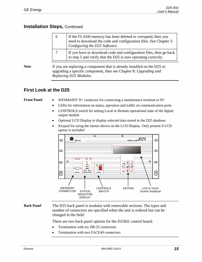
Front Panel • WESMAINT II+ connector for connecting a maintenance terminal or PC • LEDs for information on status, operation and traffic on communication ports • CONTROLS switch for setting Local or Remote operational state of the digital
output module • Optional LCD Display to display selected data stored in the D25 database • Keypad for using the menus shown on the LCD Display. Only present if LCD
option is included
Back Panel The D25 back panel is modular with removable sections. The types and number of connectors are specified when the unit is ordered but can be changed in the field.
There are two back panel options for the D25KE control board: • Termination with six DB-25 connectors • Termination with two FACE40 connectors
WESMAINT CONNECTOR STATUS
INDICATOR DISPLAY
CONTROLS SWITCH
KEYPAD LCD or Touch Screen Graphical

D25 IED User's Manual GE Energy
16 994-0081-3.00-5 General
First Look at the D25, Continued
Back Panel Diagrams
With six DB-25 connectors:
POWER
A
D25 MAINT IED / HOST 1
IED / HOST 2UTC
C
E
B
D
F
DC ANALOGINPUTS
GND XCOM 1 XCOM 2
SYSFAIL AUX KEY6 5 4 3 2 1
RADIO
J1 J2 J3
1 3 5 7 9 11 13 15 17 19 21 23 25 27 29 31 33 35 37 392 4 6 8 10 12 14 16 18 20 22 24 26 28 30 32 34 36 38 40
1 2 3 4 5 6 7 8P1
1 3 5 7 9 11 13 15 17 19 21 23 25 27 29 31 33 35 37 392 4 6 8 10 12 14 16 18 20 22 24 26 28 30 32 34 36 38 40
1 3 5 7 9 11 13 15 17 19 21 23 25 27 29 31 33 35 37 39
2 4 6 8 10 12 14 16 18 20 22 24 26 28 30 32 34 36 38 40
H
J4 J5 J6
With two FACE-40 connectors:
POWER
A
D25 MAINT IED / HOST 1
IED / HOST 2UTC
C
B
D
DC ANALOGINPUTS
GND XCOM 1 XCOM 2
SYSFAIL AUX KEY6 5 4 3 2 1
RADIO
1 3 5 7 9 11 13 15 17 19 21 23 25 27 29 31 33 35 37 392 4 6 8 10 12 14 16 18 20 22 24 26 28 30 32 34 36 38 40
1 3 5 7 9 11 13 15 17 19 21 23 25 27 29 31 33 35 37 392 4 6 8 10 12 14 16 18 20 22 24 26 28 30 32 34 36 38 40
1 3 5 7 9 11 13 15 17 19 21 23 25 27 29 31 33 35 37 39
2 4 6 8 10 12 14 16 18 20 22 24 26 28 30 32 34 36 38 40
H
E F
G2G1
Part Number The part number label on the rear of the enclosure identifies the D25 options at the time of delivery • Each digit in the part number indicates the options included in the D25 • If the D25 is modified after delivery, the part number may no longer represent
the options accurately • Update the part number label to match any option changes made after delivery
See Appendix C: Ordering Information.
GROUND STUD
POWER CONNECTIONS
POWER SWITCH
DIGITAL INPUTS
COMMUNICATION PORTS
AC ANALOG INPUTS
CONTROL OUTPUTS
AUXILIARY CONTROLS

GE Energy D25 IED User's Manual
General 994-0081-3.00-5 17
Physical Mounting
19” Rack Physical Mounting
To mount the D25 in a rack:
1. Align the D25 in the desired position in a 19-inch mounting rack.
2. Holding the D25 firmly in place in the rails of the mounting rack, install and tighten the four rack screws.
You are now ready to connect all power and field wiring to the back of the D25, see Chapter 3: Connecting Field Wiring.
! Rack Spacing
When mounting multiple D25s in a rack (or if mounting a D25 in a rack with other equipment) verify that there is at least one rack unit (RU) space above and below the D25 to allow for cooling airflow.
1 RU = 1.75 inches (44.5mm)
Required Clearances
The exterior dimensions of the standard D25 enclosure are: • 19” length x 9” deep x 8.75” high (483mm x 227mm x 222mm)
Clearance: • Allow approximately 14 inches (356 mm) of total cabinet depth to provide
clearance for hardware on the front panel, and interface cables on the rear.
Wiring Rod Installation
The optional D25 Wiring Rod assembly supports field wiring and prevents undue stress on the connectors on the rear of the D25.
You require: • Wire Rod Assembly, Part Number: 953-4029 • 2 - 6-32 - ½ inch LG Screws (screws removed from enclosure may be re-used, if
they are ½ inch long)
Mount the Wiring Rod on the back of the unit at a height where it will support cables attached to the DB-25 or FACE-40 connectors.

D25 IED User's Manual GE Energy
18 994-0081-3.00-5 General
LCD Panel Overview
LCD Panel Diagram
A Liquid Crystal Display Panel (LCD) option has been made available for applications where alphanumeric front-panel display of analog and digital system input points is desired.
M ultifunction IED D25
COMMUNICATIONSWESMAINT
Transmit Receive
XCOM 2
XCOM 1
IED 2
IED 1
Power RunOPERATION
Local Remote
CONTROLS
F1 F2
Escape Yes
F3
Tog
F4 F5 F6
F7 F8 F9
Prev ACKAlarm
Next
MenuNo
Ent
GE Energy Servicesg
+
+ +
+
This diagram shows a D25 front panel with the LCD option installed.
Detailed Description
The touch-sensitive keypad below the LCD display can be used to navigate through the display to show a set of select analog and digital input points.
The Data Display panel option is also available in a rack-mounted version that can be linked, using the RS-485 multidrop technique.
Components of an LCD Panel System
A D25 must have these components to support an LCD system: Hardware: Part #
− D25 Front Panel 953-3135 − LCD Text Display 540-0248 − LCD Circuit Board Assembly. 540-0256 − Ribbon Cable Assembly 976-0125
Continued on next page

GE Energy D25 IED User's Manual
General 994-0081-3.00-5 19
LCD Panel Overview, Continued
Configuring The Software
A D25 fitted with an LCD panel must be equipped with the Data Display DTA (B062) application software to communicate with the panel.
Using Config Pro, specific D25 database input points are mapped into this software.
LCD Hardware Connections
A flat ribbon cable (Part # 976-0125) connects from the LCD card (Part # 540-0256) to the Indicator Switch card (Part # 540-0412) which is also mounted on the inside of the front door of the D25 enclosure.
This cable is both the data and power connection to the LCD card.

D25 IED User's Manual GE Energy
20 994-0081-3.00-5 General
Graphic Display Panel Overview
GDP Diagram A Graphic Display Panel (GDP) option has been made available for applications where graphic front-panel display and control of system inputs and outputs is desired.
M ultifunction IED D25
COMMUNICATIONSWESMAINT
Transmit Receive
XCOM 2
XCOM 1
IED 2
IED 1
Power RunOPERATION
Disable Enable
CONTROLS
GE Energy Servicesg
+
++
+
This diagram shows a D25 front panel with the GDP option installed.
Detailed Description
The touch-sensitive GDP can display a selection of customized graphic displays, each representing a set of analog and digital input and output points.
Using the touch-sensitive screen, an operator can select various displays, select points to monitor and issue control commands
Components of a GDP
A D25 must have these components to support a GDP system: Hardware: Part #
− D25 Front Panel 953-3136 − GDP module 580-1186 − Ribbon Cable Assembly 976-0126 − Ribbon Cable Assembly 976-0127 − PSA module 521-0131
Continued on next page

GE Energy D25 IED User's Manual
General 994-0081-3.00-5 21
Graphic Display Panel Overview, Continued
What Can a GDP be Used For?
The GDP can eliminate the need for discrete substation devices.
For example, the GDP can be used in place of the following devices: • circuit breaker control switch and semaphore • disconnector / earth switch and semaphore • ammeter, and ammeter selector switch • voltmeter, and voltmeter selector switch • MW meter • power factor meter • alarm annunciator panel • mimic diagram.
!IMPORTANT
There are jumper settings at the back of the GDP unit that are set at the factory. These settings shall not be changed and any modification to them may cause damage to the GDP or other modules of the D25.
A D25 equipped with a GDP has these limitations: • Only external status wetting can be used when the GDP is installed.
− the D25’s power supply field O/P is used exclusively to power the GDP. − connecting another external load to the field O/P will affect isolation, and
possibly overload the power supply. • The GDP reduces the normal -20° to +70°C operational temperature rating of the
D25 to 0° to +50°C. • The 20-60 VDC D25 power supply is not available with the GDP.

D25 IED User's Manual GE Energy
22 994-0081-3.00-5 General
Configuration of a GDP
Configuring a GDP’s Software
A D25 fitted with a GDP must be equipped with Modbus DPA (A059) or DNP 3.0 DPA application software to communicate with the GDP. Using Config Pro, some or all of the D25’s database points are mapped into this communication software.
Inside the GDP, these points are then mapped into the GDP graphic objects. Note: Please contact GE for assistance in order to learn more about the
configuration tools and settings available for GDP.
GDP Hardware Connections
When installed, the PSA module (part # 521-0131) is mounted over the right-hand side of the D25’s DAC board, where it plugs onto the three sets of digital input wetting jumpers (see Low-Voltage Digital Input Card Wetting on p. 109 for more detail on these jumpers). The PSA taps into the main D25 power supply’s field output through these jumpers.
A flat ribbon cable (Part # 976-0126) connects from the PSA card to the Indicator Switch card (Part # 540-0412) mounted on the inside the front door of the D25 enclosure. This cable is the data connection to the GDP.
Another cable (Part # 976-0127) links the PSA card to the GDP. This cable is both the DC power connections from the PSA to the GDP, as well as the RS-485 data interface.

GE Energy D25 IED User's Manual
General 994-0081-3.00-5 23
Chapter 3: Connecting Field Wiring
This Section Use this section to: • Make all field wiring connections • Set external jumper configurations • Configure Serial and Ethernet ports
Power Supply
Power Supply A label on the back panel outlines the actual power connection points for the Power Supply option installed. Term # 1 2 3 4 5
-- Wetting + Wetting +/L
-- /N
Aux. Ground
+ Wetting Supply Output
Either +24V or +48V according to the power supply option specified.
- Wetting Supply Output
Either -24V or -48V according to the power supply option specified.
+/L Input • Positive if using DC power supply • Line if AC power supply
-/N Input • Negative if DC power supply • Neutral if AC power supply
!
Grounding
Connect the protective ground stud before operating the D25
Use the ground stud for shielding
External Overcurrent Protection
The D25 power supply input must be externally protected: • AC mains supplies shall be fused at no more than 15A, or • DC mains supplies shall be fused at no more than 10A

D25 IED User's Manual GE Energy
24 994-0081-3.00-5 General
Power Supply, Continued
Power Supply Source
• An IEC® 60947 compliant main disconnect switch (or other equivalent device complying with IEC 60947-1/60947-3) must be as electrically close as practical to the D25 power supply.
• For the switching power supply to operate correctly, the input voltage must be within specified limits prior to turning on the power switch.
• DC power supply modules draw an inrush current upon start-up. − Ensure the field source can supply this start-up current without overloading.
• Use the field supply outputs only when external supplies are not available. − Use of an external supply improves immunity to EMI and increases power
supply efficiency.
Digital Inputs
Digital Input Module
Note: The inputs of all variants of the S Cards are not polarity sensitive: they are bipolar, and are isolated from the D25’s internal power supply.
Digital Inputs The D25 can have up to 96 digital inputs in three banks of 32: • Digital Inputs 1 to 32 are on connectors A and B • Digital Inputs 33 to 64 are on connectors C and D • Digital Inputs 65 to 96 are on connectors E and F
Wetting Types All digital inputs require an input voltage signal large enough to turn on an optical switch. The input levels required for each D25 digital input card type are shown in the table below. • Low Voltage Digital Input cards can each be set to use:
− Externally routed PSU supplied wetting (Supplied Wetting) − External wetting − Externally applied input voltage (Voltage Detect)
• High Voltage Digital Input cards can each be set to use: − External wetting − Externally applied input voltage (Voltage Detect)

GE Energy D25 IED User's Manual
General 994-0081-3.00-5 25
Digital Inputs, Continued
Digital Input Thresholds
The table shows the on and off state thresholds for each of the listed D25 digital input card options. Before connecting field wiring, refer to the table to determine the suitability of the installed option. Verify that inputs do not exceed the maximum overload voltage, or damage to the card may result.
Card Type 32 Input Part #s
On Threshold Off Threshold Overload Voltage
Max. Power Dissipation/
Input
Low Voltage Digital Input Cards
12V / 5 mA 517-0485 >8 V <4 V 16.8 V 130 mW
24V / 5 mA 517-0486 >18 V <10 V 33.6 V 210 mW
24V / 10 mA 517-0490 >18 V <10 V 33.6 V 530 mW
48V / 5 mA 517-0487 >35 V <16 V 67.2 V 470 mW
High Voltage Digital Input Cards
120V / 1.6 mA 517-0488 >80 V <40 V 144 V 290 mW
250V / 1.2 mA 517-0489 >160 V <80 V 300 V 450 mW
Note The inputs of all variants of the D25 digital input cards are not polarity sensitive: they are bipolar, and are isolated from the D25’s internal power supply.
Fuse Monitoring
D25 digital input modules include circuitry that detects the presence of wetting voltage after it has passed through the fuse F1.
Software in the D25 Plant I/O Subsystem (P097 V2.30 or greater) responds to the signals from each of the three D25 digital input modules and creates pseudo digital inputs that can be seen in the D25 System Point Database.
If fuse F1 opens or the wetting voltage is removed from the digital input module for any reason, the pseudo DI for that module will change state and set an alarm. If a D25 digital input module is not present, the pseudo DI point will remain in the Off state.
Note: Fuse monitoring can only detect a wetting voltage if the D25 digital input module is configured for supplied or external wetting. If the module is configured for voltage detect the fuse monitoring circuitry will not sense any wetting voltage, and remains in the Off state

D25 IED User's Manual GE Energy
26 994-0081-3.00-5 General
Digital Inputs, Continued
Digital Input Field Connections
Field wiring for all variations of Digital Input modules are made through two FACE-40 connectors for each module on the backplane of the D25 enclosure. These connectors are provided only if a digital input module is installed in the D25.
Digital Input Wetting Selection
Wetting supply source must be provided externally and independently for each digital input card.
To use external or supplied wetting: • Connect external wetting supply to pins 1 and 2 on FACE-40 Connector A, C
and/or E.
To use the voltage detect input: • Connect (jumper) pins 1 and 2 on Connector A, C and/or E for each module(s). Note: Internal wetting voltage to Digital Cards is no longer available. Please refer to Product Bulletin PRBT-213.
!
External Power Sources
While all of the 32 inputs are bipolar and not polarity sensitive, the “B” sides of all inputs are linked together. • Use care when connecting multiple external power sources.
For external wetting, the three digital input modules can have independent wetting configurations and wetting voltage sources.
Digital Inputs Supplied Wetting (Externally routed)
Supplied Wetting is when the voltage applied to the inputs originates from the power supply internal to the D25, routed externally to the DI Cards. The digital input is “turned on” simply by closing a contact across the two input termination points.
Connections for digital input point number 1. DI Connector A
1 2 3 4 39 40
Input #1Contacts
Power Supply Term. Block
1 2 3 4 5
+ Wetting
- Wetting
Notes This option is available for 24 and 48V low-voltage DI cards, only. Supplied Wetting option is not available if the Graphics Display panel is installed because it reduces the isolation, increasing the D25 unit’s susceptibility to EMI and transient interference.

GE Energy D25 IED User's Manual
General 994-0081-3.00-5 27
Digital Inputs, Continued
Digital Inputs External Wetting
With External Wetting, operation of the digital inputs is essentially the same as for Supplied Wetting, except that the voltage that is switched at the input terminals is supplied by an external (non-D25) source. The external power source is connected to pins 1 and 2 of Connector(s) A, C or E, for each of the three Digital Input cards respectively.
Connections for digital input point number 1:
DC
ConnectorA
Pin # 1 2 3 4 39 40
Input #1Contacts
External WettingPower Supply
Voltage Detect In this type of input, the D25 does not provide the wetting power source, from either its own power supply, or from an external battery.
Note: Pins 1 and 2 of Connector(s) A, C or E are jumpered for each board using this configuration.
If using more than one external power source, they must share a common return, and it must be connected to the “B” input termination for each input point.
Connections for digital input point number 1:

D25 IED User's Manual GE Energy
28 994-0081-3.00-5 General
Digital Inputs, Continued
Table: Digital Inputs Pinouts 1-32
Pinouts for Digital Inputs 1 through 32:
Pin Connector A Connector B 1 Wetting Voltage Reserved 2 Wetting Voltage Reserved 3 DI 1A DI 17A 4 DI 1B DI 17B 5 DI 2A DI 18A 6 DI 2B DI 18B 7 DI 3A DI 19A 8 DI 3B DI 19B 9 DI 4A DI 20A
10 DI 4B DI 20B 11 DI 5A DI 21A 12 DI 5B DI 21B 13 DI 6A DI 22A 14 DI 6B DI 22B 15 DI 7A DI 23A 16 DI 7B DI 23B 17 DI 8A DI 24A 18 DI 8B DI 24B 19 Reserved Reserved 20 Reserved Reserved 21 Reserved Reserved 22 Reserved Reserved 23 Reserved Reserved 24 Reserved Reserved 25 DI 9A DI 25A 26 DI 9B DI 25B 27 DI 10A DI 26A 28 DI 10B DI 26B 29 DI 11A DI 27A 30 DI 11B DI 27B 31 DI 12A DI 28A 32 DI 12B DI 28B 33 DI 13A DI 29A 34 DI 13B DI 29B 35 DI 14A DI 30A 36 DI 14B DI 30B 37 DI 15A DI 31A 38 DI 15B DI 31B 39 DI 16A DI 32A 40 DI 16B DI 32B

GE Energy D25 IED User's Manual
General 994-0081-3.00-5 29
Digital Inputs, Continued
Table: Digital Inputs Pinouts 33-64
Pinouts for Digital Inputs 33 through 64:
Pin Connector C Connector D 1 Wetting Voltage Reserved 2 Wetting Voltage Reserved 3 DI 33A DI 49A 4 DI 33B DI 49B 5 DI 34A DI 50A 6 DI 34B DI 50B 7 DI 35A DI 51A 8 DI 35B DI 51B 9 DI 36A DI 52A
10 DI 36B DI 52B 11 DI 37A DI 53A 12 DI 37B DI 53B 13 DI 38A DI 54A 14 DI 38B DI 54B 15 DI 39A DI 55A 16 DI 39B DI 55B 17 DI 40A DI 56A 18 DI 40B DI 56B 19 Reserved Reserved 20 Reserved Reserved 21 Reserved Reserved 22 Reserved Reserved 23 Reserved Reserved 24 Reserved Reserved 25 DI 41A DI 57A 26 DI 41B DI 57B 27 DI 42A DI 58A 28 DI 42B DI 58B 29 DI 43A DI 59A 30 DI 43B DI 59B
31 DI 44A DI 60A 32 DI 44B DI 60B 33 DI 45A DI 61A 34 DI 45B DI 61B 35 DI 46A DI 62A 36 DI 46B DI 62B 37 DI 47A DI 63A 38 DI 47B DI 63B 39 DI 48A DI 64A 40 DI 48B DI 64B

D25 IED User's Manual GE Energy
30 994-0081-3.00-5 General
Digital Inputs, Continued
Table: Digital Inputs Pinouts 65-96
Pinouts for Digital Inputs 65 through 96.
Pin Connector E Connector F 1 Wetting Voltage Reserved 2 Wetting Voltage Reserved 3 DI 65A DI 81A 4 DI 65B DI 81B 5 DI 66A DI 82A 6 DI 66B DI 82B 7 DI 67A DI 83A 8 DI 67B DI 83B 9 DI 68A DI 84A
10 DI 68B DI 84B 11 DI 69A DI 85A 12 DI 69B DI 85B 13 DI 70A DI 86A 14 DI 70B DI 86B 15 DI 71A DI 87A 16 DI 71B DI 87B 17 DI 72A DI 88A 18 DI 72B DI 88B 19 Reserved Reserved 20 Reserved Reserved 21 Reserved Reserved 22 Reserved Reserved 23 Reserved Reserved 24 Reserved Reserved 25 DI 73A DI 89A 26 DI 73B DI 89B 27 DI 74A DI 90A 28 DI 74B DI 90B 29 DI 75A DI 91A 30 DI 75B DI 91B 31 DI 76A DI 92A 32 DI 76B DI 92B 33 DI 77A DI 93A 34 DI 77B DI 93B 35 DI 78A DI 94A 36 DI 78B DI 94B 37 DI 79A DI 95A 38 DI 79B DI 95B 39 DI 80A DI 96A 40 DI 80B DI 96B

GE Energy D25 IED User's Manual
General 994-0081-3.00-5 31
Control Outputs
Control Module The control module can be configured for two basic modes of operation: • Trip/Close (T/C) – excluding D25 High Current KE Control Card • Digital Output (DO)
Any other type of operation, such as Raise/Lower, uses the Digital Output hardware configuration.
T/C or DO (R/L) Sensing
D25 software detects what type of digital output command has been received, and uses the Master Trip and Master Close relays when appropriate.
External jumpering is provided to route the external Control Voltage through the correct relays for each mode of operation.
Fuse Monitoring
The control module includes circuitry that detects the presence of control voltage on the load side of the fuses. Software in the D25 Plant I/O Subsystem (P097 V2.30 or greater) responds to the signal from the control module and creates a pseudo digital input that can be seen in the D25 System Point Database.
If a fuse opens, or the control voltage is removed from the digital output module for any reason, the pseudo digital input (DI) for that module will change state and set an alarm.
If the control module is not present, the pseudo DI point will remain in the Off state. Note 1: The fuse monitoring circuitry can only detect a control voltage above
approximately 10 Vdc. If the control voltage is less than this level, the fuse monitoring circuitry will not sense any voltage, and the pseudo DI point will remain in the Off state.
Note 2: Fuse monitoring works with (+) ve or (-) ve grounded systems.
Note 3: For D25s with Plant I/O Version 2.30, the fuse-monitoring feature will only work with DC control voltages. Versions greater than 2.30 support AC control voltage monitoring.
Note 4: The D25 High Current Control Card does not have a fuse and a fuse monitoring circuit.
!
Caution
The fuse monitoring circuitry has been engineered to detect control voltages up to the supported maximum specifications of the module. Do not exceed this level of control voltage. Damage to the module may result.
Note The D25 KE control module does not require hardware configuration to use the fuse-monitoring feature.

D25 IED User's Manual GE Energy
32 994-0081-3.00-5 General
Control Outputs, Continued
D25KE Module External Connections
The D25KE Control Module contains (up to) 32 digital output relays, either: • divided into (up to) 4 groups of 8 relays
− each group is separately configurable as trip/close (T/C) pairs, or raise/lower (R/L) pairs via field selectable jumpers
• divided into (1 or) 2 groups of 8 pairs of relays (D25KE-4Z Card) − each group is separately configurable as T/C or R/L
D25KE Variations
The D25KE control modules are available in two variations: • with 6 DB-25 connectors for field wiring and one 8-pin compression terminal
block for optioning • with up to 2 FACE-40 connectors for field wiring and optioning
About D25 KE Rear Panels
All DB-25 type D25KE modules are installed in a D25 enclosure that has six DB-25 connectors on the backplane, regardless of how many channels the KE board has. • a 16 channel DB-25 KE module will have two DB-25 connectors that will not be
used.
A D25 KE module installed in an enclosure with FACE-40 connectors will only have the connectors necessary to support the number of channels in use. • 32 channel D25 KE module will have two FACE-40 connectors, 16 channel
module will have only one FACE-40 connector installed.
Output Options The 32 D25KE digital outputs are divided into up to four groups of eight relays. • Each of the four groups is independently configurable as Trip/Close pairs or
Raise/Lower Digital Outputs.
External Jumper Configuration
• Insert wire jumpers in the rear 8-pin compression type connector P1 to configure the D25KE DB-25 module.
Note: Use GE Energy quad-wire jumper, part # 970-0264, or make an equivalent jumper, as desired.
• Jumper the two FACE-40 connectors G1 and G2 to configure the D25KE FACE-40 module.

GE Energy D25 IED User's Manual
General 994-0081-3.00-5 33
Control Outputs, Continued
Table: D25KE DB-25 Connector Pinouts J1 to J3
The DB-25 connector pinouts for D25KE outputs 1 through 16. Note: TRPx = Trip output point x
CLSx = Close output point x
NC = Not Connected
J1 DB-25 Pin
Signal J2 DB-25 Pin
Signal J3 DB-25 Pin
Signal
1 TRP1 1 TRP9 1 TRP1
2 CLS1 2 CLS9 2 TRP2
3 TRP2 3 TRP10 3 TRP3
4 CLS2 4 CLS10 4 TRP4
5 TRP3 5 TRP11 5 TRP5
6 CLS3 6 CLS11 6 TRP6
7 TRP4 7 TRP12 7 TRP7
8 CLS4 8 CLS12 8 TRP8
9 TRP5 9 TRP13 9 TRP9
10 CLS5 10 CLS13 10 TRP10
11 TRP6 11 TRP14 11 TRP11
12 CLS6 12 CLS14 12 TRP12
13 TRP7 13 TRP15 13 TRP13
14 CLS7 14 CLS15 14 TRP14
15 TRP8 15 TRP16 15 TRP15
16 CLS8 16 CLS16 16 TRP16
17 NC 17 NC 17-25 NC
18-25 COIL_SUP_RTN 18-25 COIL_SUP_RTN

D25 IED User's Manual GE Energy
34 994-0081-3.00-5 General
Control Outputs, Continued
Table: D25KE DB-25 Connector Pinouts J4 to J6
The DB-25 connector pinouts for D25KE outputs 17 through 32.
J4 DB-25 Pin
Signal J5 DB-25 Pin
Signal J6 DB-25 Pin
Signal
1 TRP17 1 TRP25 1 TRP17
2 CLS17 2 CLS25 2 TRP18
3 TRP18 3 TRP26 3 TRP19
4 CLS18 4 CLS26 4 TRP20
5 TRP19 5 TRP27 5 TRP21
6 CLS19 6 CLS27 6 TRP22
7 TRP20 7 TRP28 7 TRP23
8 CLS20 8 CLS28 8 TRP24
9 TRP21 9 TRP29 9 TRP25
10 CLS21 10 CLS29 10 TRP26
11 TRP22 11 TRP30 11 TRP27
12 CLS22 12 CLS30 12 TRP28
13 TRP23 13 TRP31 13 TRP29
14 CLS23 14 CLS31 14 TRP30
15 TRP24 15 TRP32 15 TRP31
16 CLS24 16 CLS32 16 TRP32
17 NC 17 NC 17-25 NC
18-25 COIL_SUP_RTN 18-25 COIL_SUP_RTN

GE Energy D25 IED User's Manual
General 994-0081-3.00-5 35
Control Outputs, Continued
Table: D25KE DB-25 Control Function Terminal Block – P1
Phoenix 8-pin terminal block – P1 Pinout:
P1 Pin
Signal Function Comments
1 COIL_SUP Control Voltage Interposer Relay Coil Power Supply connections
2 COIL_SUP_RTN
Control Voltage return
3 JMP1 Relays 1-8 mode jumper point
Jumper to Pin 1-5 (+VC) for R/L
Jumper to Pin 1-6 (MT) for T/C
4 JMP2 Relays 9-16 mode jumper point
Jumper to Pin 1-5 (+VC) for R/L
Jumper to Pin 1-6 (MT) for T/C
5 +VC Control Voltage (fused) Jumper to JMP1 through 4 for R/L
6 MT Master Trip Bus Jumper to JMP1 through 4 for T/C
7 JMP3 Relays 17-24 mode jumper point
Jumper to Pin 1-5 (+VC) for R/L
Jumper to Pin 1-6 (MT) for T/C
8 JMP4 Relays 25-32 mode jumper point
Jumper to Pin 1-5 (+VC) for R/L
Jumper to Pin 1-6 (MT) for T/C
1 2 3 4 5 6 7 8

D25 IED User's Manual GE Energy
36 994-0081-3.00-5 General
Control Outputs, Continued
D25KE DB-25 Control Voltage Connections
Control voltage can be supplied by either an external power supply, or the D25’s own power supply. In either case, connect the control voltage to P1 pins 1 and 2.
To provide control voltage using the D25 internal supply, connect as shown:
POWER
A
D25 M
UT
C
E
DC ANALOGINPUTS
GND
SYSFAIL AUX KEY6 5 4 3 2 1
RADIO
J1 J2 J3
1 3 5 7 9 11 13 15 17 19 21 23 25 27 29 31 33 35 37 392 4 6 8 10 12 14 16 18 20 22 24 26 28 30 32 34 36 38 40
1 2 3 4 5 6 7 8
2 Jumpers Requiredto provide ControlVoltage from D25
Power Supply
Connect from D25Power Supply:-Term 1 to P1-1-Term 2 to P1-2
P1
1 3 5 2 4
1 3 5 7 9 11 13 15 17 19 21 23 25 27 29 31
2 4 6 8 10 12 14 16 18 20 22 24 26 28 30 32
H
Note: The (external) control voltage can be up to 75 Vdc or 50 Vac.

GE Energy D25 IED User's Manual
General 994-0081-3.00-5 37
Control Outputs, Continued
D25KE DB-25 Trip/Close Configuration
Through the use of “Master” relays, the 32 digital outputs can be configured as four groups of eight Trip/Close pairs, that is, 64 output connections. Note: The Control Voltage can be up to 75 Vdc or 50 Vac. See page 141
for specifications of control outputs.
P1 connections for Trip/Close
Use jumper wires on the Control Function Terminal block P1 to configure:
Group 1: • connect between MT (P1-6) and JMP1 (P1-3)
Group 2: • connect between MT (P1-6) and JMP2 (P1-4)
Group 3: • connect between MT (P1-6) and JMP3 (P1-7)
Group 4: • connect between MT (P1-6) and JMP4 (P1-8)
T/C 1 - 8 T/C 25 - 32
P1
T/C 9 - 16
1 2 3 4 5 6 7 8
Control Voltage
Control Voltage Return
T/C 17 - 24

D25 IED User's Manual GE Energy
38 994-0081-3.00-5 General
Control Outputs, Continued
About the DB-25 Option
The D25KE DB-25 connector option is for use primarily with WESTERM D20 KI interposing relay panels (part numbers 517-0166 and 517-0167).
For this connection use a multi-conductor shielded DB-25 cable assembly.
Note Ensure that the multi-conductor cable’s shield drain wire is connected to pin 17 of the WESTERM D20 KI DB-25 connector.
Pin 17 of the D25KE DB-25 connector is not connected internally, and therefore, cannot be used as a drain connection.
Note For Trip/Close operation, the cables used to connect the D25 control outputs to the D20 KI panels must have all DB-25 pins connected end-to-end. • Use GE Energy part number 977-0208, or equivalent.
Trip/Close Connections to Interposing Relay Panels
The D25KE module requires four WESTERM KI interposing relay panels to support 32 pairs of Trip/Close digital outputs. Note: For all KI relay panels, one of the Z1 jumpers must be installed to
provide a return path for the control voltage. KI panels have these jumpers installed.
First group of eight digital outputs: • Connect a DB-25 cable from J1 of the D25KE to J2 of the first WESTERM KI
interposing relay panel.
Second group of eight digital outputs: • Connect a DB-25 cable from J2 of the D25KE to J2 of the second WESTERM
KI interposing relay panel.
Third group of eight digital outputs: • Connect a DB-25 cable from J4 of the D25KE to J2 of the third WESTERM KI
interposing relay panel.
Fourth group of eight digital outputs: • Connect a DB-25 cable from J5 of the D25KE to J2 of the fourth WESTERM KI
interposing relay panel

GE Energy D25 IED User's Manual
General 994-0081-3.00-5 39
Control Outputs, Continued
D25KE Trip/Close Connection Diagram
Shows the connections used when configuring a D25KE module for Trip/Close operation using up to four-D20 KI interposing relay panels.
D25KECONTROLOUTPUTS
GROUNDINGPOINT for D25
TB9
J1
J2 J3
Z1
Z2Z3Z4Z5Z6Z7Z8Z9
D20 KITrip/Close
Points 9 - 16InterposingRelay Panel
TB9
J1
J2 J3
Z1
Z2Z3Z4Z5Z6Z7Z8Z9
POWER
A
D25 MAINT IED / HOST 1
IED / HOST 2UTC
C
E
B
D
F
DC ANALOGINPUTS
GND XCOM 1 XCOM 2
SYSFAIL AUX KEY6 5 4 3 2 1
RADIO
J1 J2 J3
1 3 5 7 9 11 13 15 17 19 21 23 25 27 29 31 33 35 37 392 4 6 8 10 12 14 16 18 20 22 24 26 28 30 32 34 36 38 40
1 2 3 4 5 6 7 8P1
1 3 5 7 9 11 13 15 17 19 21 23 25 27 29 31 33 35 37 392 4 6 8 10 12 14 16 18 20 22 24 26 28 30 32 34 36 38 40
1 3 5 7 9 11 13 15 17 19 21 23 25 27 29 31 33 35 37 39
2 4 6 8 10 12 14 16 18 20 22 24 26 28 30 32 34 36 38 40
H
J4 J5 J6
D20 KITrip/ClosePoints 1 - 8InterposingRelay Panel
To:D20 KI
Trip/ClosePoints 17 - 24InterposingRelay Panel
To:D20 KI
Trip/ClosePoints 25 - 32InterposingRelay Panel

D25 IED User's Manual GE Energy
40 994-0081-3.00-5 General
Control Outputs, Continued
D25KE DB-25 Raise/Lower Configuration
The 32 digital outputs can be configured as four groups of four Raise/Lower pairs. Note: The (external) control voltage can be up to 75 Vdc or 50 Vac, at 2 A maximum.
P1 connections for Raise/Lower
Use jumper wires on the Control Function Terminal block to configure:
Group 1: • connect between +VC (P1-5) and JMP1 (P1-3)
Group 2: • connect between +VC (P1-5) and JMP2 (P1-4)
Group 3: • connect between +VC (P1-5) and JMP3 (P1-7)
Group 4: • connect between +VC (P1-5) and JMP4 (P1-8)
Note Raise/Lower Digital Outputs are numbered in the reverse order: Lower point #1 is Digital Output point #32
Raise/Lower Connections to Interposing Relay Panels
The D25KE module requires two WESTERM KI interposing relay panels to support 16 pairs of Raise/Lower digital outputs. To configure and connect the digital outputs: • Connect a DB-25 cable from J3 of the D25KE to J1 of the first WESTERM KI
interposing relay panel. • Connect another DB-25 cable from J6 of the D25KE to J1 of the second
WESTERM KI interposing relay panel. • Connect a Control Voltage Return connection from the D25KE’s P1-2 to each of
the D20 KI’s TB9-1 • Set both WESTERM KI’s Jumpers Z2 – 9 to 2 - 3
Control Voltage Return
P1
R/L 12 - 9
R/L 16 - 13
1 2 3 4 5 6 7 8
Control Voltage
R/L 4 - 1
R/L 8 - 5

GE Energy D25 IED User's Manual
General 994-0081-3.00-5 41
Control Outputs, Continued
D25KE Raise/Lower Connection Diagram
Shows the connections used when configuring for Raise/Lower operation using two D20 KI interposing relay panels.
D25KECONTROLOUTPUTS
GROUNDINGPOINT for D25
TB9
J1
J2 J3
Z1
Z2Z3Z4Z5Z6Z7Z8Z9
TB9
J1
J2 J3
Z1
Z2Z3Z4Z5Z6Z7Z8Z9
POWER
A
D25 MAINT IED / HOST 1
IED / HOST 2UTC
C
E
B
D
F
DC ANALOGINPUTS
GND XCOM 1 XCOM 2
SYSFAIL AUX KEY6 5 4 3 2 1
RADIO
J1 J2 J3
1 3 5 7 9 11 13 15 17 19 21 23 25 27 29 31 33 35 37 392 4 6 8 10 12 14 16 18 20 22 24 26 28 30 32 34 36 38 40
1 2 3 4 5 6 7 8P1
1 3 5 7 9 11 13 15 17 19 21 23 25 27 29 31 33 35 37 392 4 6 8 10 12 14 16 18 20 22 24 26 28 30 32 34 36 38 40
1 3 5 7 9 11 13 15 17 19 21 23 25 27 29 31 33 35 37 39
2 4 6 8 10 12 14 16 18 20 22 24 26 28 30 32 34 36 38 40
H
J4 J5 J6
D20 KIRaise/LowerPoints 9 - 16InterposingRelay Panel
Connect P1-2to TB9-1 of
bothInterposing
Relay Panelsas a control
voltage return
Jumpers Z1 - 9in position 2-3
for Raise/Lower
D20 KIRaise/LowerPoints 1 - 8InterposingRelay Panel

D25 IED User's Manual GE Energy
42 994-0081-3.00-5 General
Control Outputs, Continued
D25KE DB-25 Combined R/L and T/C
Trip/Close and Raise/Lower digital outputs can be used on the same D25KE DB-25 module.
Note The three examples shown below are the only recommended configuration options for combining trip/close and raise/lower in one D25KE.
Do Not configure raise/lower points with point numbers lower than the trip/close point numbers as it may result in wiring problems, and interposing relay connection problems.
Combined T/C and R/L Example #1
In the following example, the first 24 digital outputs are configured as trip/close, and the last 8 are configured as 4 raise/lower pairs.
P1 connections for Combined Raise/Lower and Trip/Close
P1
T/C 9 - 16
T/C 1 - 8
1 2 3 4 5 6 7 8
Control Voltage
Control Voltage Return
R/L 4 - 1
T/C 17 - 24

GE Energy D25 IED User's Manual
General 994-0081-3.00-5 43
Control Outputs, Continued
Combined T/C and R/L Example #2
This example shows the P1 jumpers when the first 16 digital outputs are configured as trip/close, and the second 16 outputs are configured as 8 raise/lower pairs.
P1 connections for Combined Trip/Close and Raise/Lower
Combined T/C and R/L Example #3
This example shows the P1 jumpers when the first 8 digital outputs are configured as trip/close, and the second 24 outputs are configured as 12 raise/lower pairs.
P1 connections for Combined Trip/Close and Raise/Lower
P1
T/C 9 - 16
T/C 1 - 8
1 2 3 4 5 6 7 8
Control Voltage
Control Voltage Return
R/L 4 - 1
R/L 8 - 5
P1
T/C 1 - 8
1 2 3 4 5 6 7 8
Control Voltage
Control Voltage Return
R/L 4 - 1
R/L 8 - 5
R/L12 - 9

D25 IED User's Manual GE Energy
44 994-0081-3.00-5 General
Control Outputs, Continued
Table: Connector G1 Pinouts
D25KE Digital Output Connections: Pinouts for FACE-40 Connector G1, outputs 1 to 16.
G1 Pin Signal G1 Pin Signal G1 Pin Signal
1 COIL_SUP 15 CLS7 29 CLS14
2 COIL_RTN 16 TRP7 30 TRP14
3 CLS1 17 CLS8 31 CLS15
4 TRP1 18 TRP8 32 TRP15
5 CLS2 19 CLS9 33 CLS16
6 TRP2 20 TRP9 34 TRP16
7 CLS3 21 CLS10 35 VCA
8 TRP3 22 TRP10 36 VCA
9 CLS4 23 CLS11 37 JMP1
10 TRP4 24 TRP11 38 JMP2
11 CLS5 25 CLS12 39 MTA
12 TRP5 26 TRP12 40 MTA
13 CLS6 27 CLS13
14 TRP6 28 TRP13
Table: Connector G2 Pinouts
Pinouts for FACE-40 Connector G2 outputs 17 to 32.
G2 Pin Signal G2 Pin Signal G2 Pin Signal
1 VCB 15 CLS20 29 CLS27
2 VCB 16 TRP20 30 TRP27
3 JMP3 17 CLS21 31 CLS28
4 JMP4 18 TRP21 32 TRP28
5 MTB 19 CLS22 33 CLS29
6 MTB 20 CLS22 34 TRP29
7 MCA 21 CLS23 35 CLS30
8 MCB 22 TRP23 36 TRP30
9 CLS17 23 CLS24 37 CLS31
10 TRP17 24 TRP24 38 TRP31
11 CLS18 25 CLS25 39 CLS32
12 TRP18 26 TRP25 40 TRP32
13 CLS19 27 CLS26
14 TRP19 28 TRP26
GE Energy D25 IED User's Manual
General 994-0081-3.00-5 45
Control Outputs, Continued
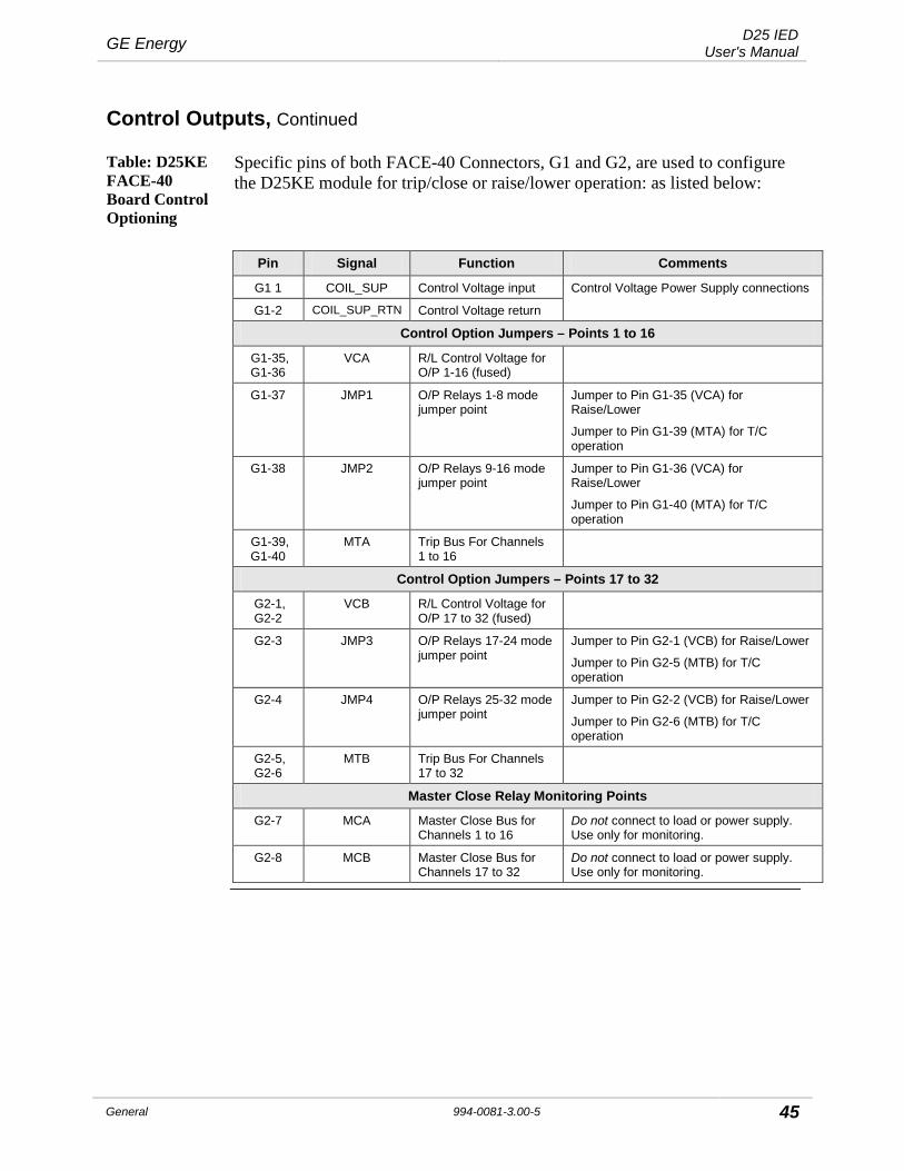
Table: D25KE FACE-40 Board Control Optioning
Specific pins of both FACE-40 Connectors, G1 and G2, are used to configure the D25KE module for trip/close or raise/lower operation: as listed below:
Pin Signal Function Comments
G1 1 COIL_SUP Control Voltage input Control Voltage Power Supply connections
G1-2 COIL_SUP_RTN Control Voltage return
Control Option Jumpers – Points 1 to 16
G1-35, G1-36
VCA R/L Control Voltage for O/P 1-16 (fused)
G1-37 JMP1 O/P Relays 1-8 mode jumper point
Jumper to Pin G1-35 (VCA) for Raise/Lower
Jumper to Pin G1-39 (MTA) for T/C operation
G1-38 JMP2 O/P Relays 9-16 mode jumper point
Jumper to Pin G1-36 (VCA) for Raise/Lower
Jumper to Pin G1-40 (MTA) for T/C operation
G1-39, G1-40
MTA Trip Bus For Channels 1 to 16
Control Option Jumpers – Points 17 to 32
G2-1, G2-2
VCB R/L Control Voltage for O/P 17 to 32 (fused)
G2-3 JMP3 O/P Relays 17-24 mode jumper point
Jumper to Pin G2-1 (VCB) for Raise/Lower
Jumper to Pin G2-5 (MTB) for T/C operation
G2-4 JMP4 O/P Relays 25-32 mode jumper point
Jumper to Pin G2-2 (VCB) for Raise/Lower
Jumper to Pin G2-6 (MTB) for T/C operation
G2-5, G2-6
MTB Trip Bus For Channels 17 to 32
Master Close Relay Monitoring Points
G2-7 MCA Master Close Bus for Channels 1 to 16
Do not connect to load or power supply. Use only for monitoring.
G2-8 MCB Master Close Bus for Channels 17 to 32
Do not connect to load or power supply. Use only for monitoring.

D25 IED User's Manual GE Energy
46 994-0081-3.00-5 General
Control Outputs, Continued
D25KE FACE-40 Module Control Voltage Connections
Control voltage can be supplied by either an external power supply, or the D25’s own power supply. Connect the control voltage to G1 pins 1 and 2. Note: The (external) control voltage can be up to 120 Vdc. See page 141
for specifications of control outputs.
To provide control voltage using the D25 internal power supply, connect as shown:
POWER
A
C
DC ANALOGINPUTS
GND
SYSFAIL AUX KE6 5 4 3 2
RAD
1 3 5 7 9 11 13 15 17 19 21 23 25 27 29 31 33 35 37 392 4 6 8 10 12 14 16 18 20 22 24 26 28 30 32 34 36 38 4
2 Jumpers Requiredto provide ControlVoltage from D25
Power Supply
Connect from D25Power Supply:-Term 1 to G1-1-Term 2 to G1-2
1 3 5 7 9 11 13 15 17 19 21
2 4 6 8 10 12 14 16 18 20 22
H
E
G1

GE Energy D25 IED User's Manual
General 994-0081-3.00-5 47
Control Outputs, Continued
D25KE FACE-40 Trip/Close Configuration
Through the use of “Master” relays, the 32 digital outputs can be configured as four groups of eight Trip/Close pairs: 64 output connections. Note: The control voltage can be up to 120 Vdc. See page 141 for
specifications of control outputs.
G1 and G2 Connections for Trip/Close
Use jumper wires on the FACE-40 terminal block G1 to configure groups 1 and 2. • Group 1:
− connect between MTA (G1-39) and JMP1 (G1-37) • Group 2:
− connect between MTA (G1-40) and JMP2 (G1-38)
1 3 5 7 9 11 13 15 17 19 21 23 25 27 29 31 33 35 37 39
2 4 6 8 10 12 14 16 18 20 22 24 26 28 30 32 34 36 38 40
G11 3 5 7 9 11 13 15 17 19 21 23 25 27 29 31 33 35 37 39
2 4 6 8 10 12 14 16 18 20 22 24 26 28 30 32 34 36 38 40
G2
Use jumper wires on the FACE-40 terminal block G2 to configure groups 3 and 4. • Group 3:
− connect between MTB (G2-5) and JMP3 (G2-3) • Group 4:
− connect between MTB (G2-6) and JMP4 (G2-4)

D25 IED User's Manual GE Energy
48 994-0081-3.00-5 General
Control Outputs, Continued
D25KE FACE-40 Raise/Lower Configuration
The 32 digital outputs can be configured as four groups of four Raise/Lower pairs. Note: The control voltage can be up to 120 Vdc. See page 141 for
specifications of control outputs.
G1 and G2 Connections for Raise/Lower
Use jumper wires on the FACE-40 terminal block G1 to configure groups 1 and 2. • Group 1:
− connect between VCA (G1-35) and JMP1 (G1-37) • Group 2:
− connect between VCA (G1-36) and JMP2 (G1-38)
1 3 5 7 9 11 13 15 17 19 21 23 25 27 29 31 33 35 37 39
2 4 6 8 10 12 14 16 18 20 22 24 26 28 30 32 34 36 38 40
G11 3 5 7 9 11 13 15 17 19 21 23 25 27 29 31 33 35 37 39
2 4 6 8 10 12 14 16 18 20 22 24 26 28 30 32 34 36 38 40
G2
Use jumper wires on the FACE-40 terminal block G2 to configure groups 3 and 4. • Group 3:
− connect between VCB (G2-1) and JMP3 (G2-3) • Group 4:
− connect between VCB (G2-2) and JMP4 (G2-4)
GE Energy D25 IED User's Manual
General 994-0081-3.00-5 49
Control Outputs, Continued
D25KE FACE-40 Combined R/L and T/C
Trip/Close and Raise/Lower digital outputs can be used on the same D25KE FACE-40 unit.
When assigning raise/lower groups, always start with group 4, then group 3, and lastly group 2.
Remember that raise/lower points number in the reverse direction from other point types: point 32 will become lower point 1.
Note Configuring raise/lower groups with numbers lower than the trip/close group numbers, or between trip/close groups can result in a very complex and confusing wiring scheme.
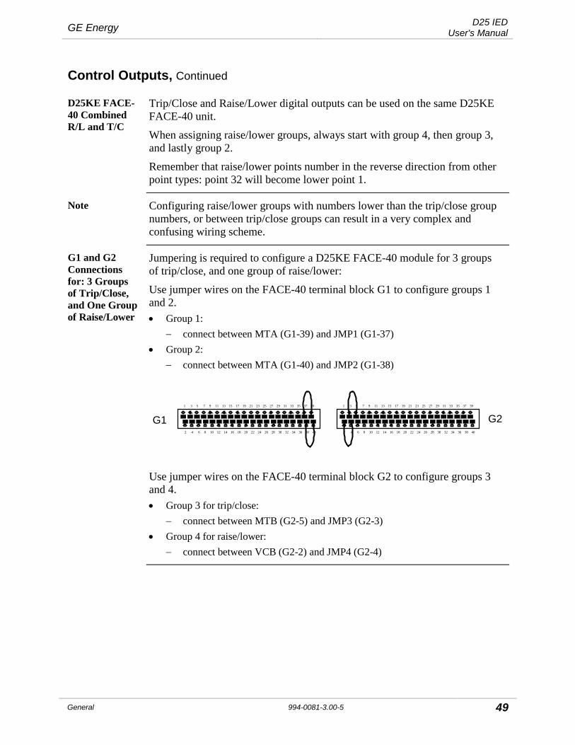
G1 and G2 Connections for: 3 Groups of Trip/Close, and One Group of Raise/Lower
Jumpering is required to configure a D25KE FACE-40 module for 3 groups of trip/close, and one group of raise/lower:
Use jumper wires on the FACE-40 terminal block G1 to configure groups 1 and 2. • Group 1:
− connect between MTA (G1-39) and JMP1 (G1-37) • Group 2:
− connect between MTA (G1-40) and JMP2 (G1-38)
1 3 5 7 9 11 13 15 17 19 21 23 25 27 29 31 33 35 37 39
2 4 6 8 10 12 14 16 18 20 22 24 26 28 30 32 34 36 38 40
G11 3 5 7 9 11 13 15 17 19 21 23 25 27 29 31 33 35 37 39
2 4 6 8 10 12 14 16 18 20 22 24 26 28 30 32 34 36 38 40
G2
Use jumper wires on the FACE-40 terminal block G2 to configure groups 3 and 4. • Group 3 for trip/close:
− connect between MTB (G2-5) and JMP3 (G2-3) • Group 4 for raise/lower:
− connect between VCB (G2-2) and JMP4 (G2-4)
D25 IED User's Manual GE Energy
50 994-0081-3.00-5 General
Control Outputs, Continued
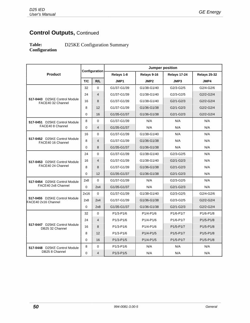
Table: Configuration
D25KE Configuration Summary
Product Configuration
Jumper position
Relays 1-8 Relays 9-16 Relays 17-24 Relays 25-32
T/C R/L JMP1 JMP2 JMP3 JMP4
517-0443 D25KE Control Module FACE40 32 Channel
32 0 G1/37-G1/39 G1/38-G1/40 G2/3-G2/5 G2/4-G2/6
24 4 G1/37-G1/39 G1/38-G1/40 G2/3-G2/5 G2/2-G2/4
16 8 G1/37-G1/39 G1/38-G1/40 G2/1-G2/3 G2/2-G2/4
8 12 G1/37-G1/39 G1/36-G1/38 G2/1-G2/3 G2/2-G2/4
0 16 G1/35-G1/37 G1/36-G1/38 G2/1-G2/3 G2/2-G2/4
517-0451 D25KE Control Module FACE40 8 Channel
8 0 G1/37-G1/39 N/A N/A N/A
0 4 G1/35-G1/37 N/A N/A N/A
517-0452 D25KE Control Module FACE40 16 Channel
16 0 G1/37-G1/39 G1/38-G1/40 N/A N/A
8 4 G1/37-G1/39 G1/36-G1/38 N/A N/A
0 8 G1/35-G1/37 G1/36-G1/38 N/A N/A
517-0453 D25KE Control Module FACE40 24 Channel
24 0 G1/37-G1/39 G1/38-G1/40 G2/3-G2/5 N/A
16 4 G1/37-G1/39 G1/38-G1/40 G2/1-G2/3 N/A
8 8 G1/37-G1/39 G1/36-G1/38 G2/1-G2/3 N/A
0 12 G1/35-G1/37 G1/36-G1/38 G2/1-G2/3 N/A
517-0454 D25KE Control Module FACE40 2x8 Channel
2x8 0 G1/37-G1/39 N/A G2/3-G2/5 N/A
0 2x4 G1/35-G1/37 N/A G2/1-G2/3 N/A
517-0455 D25KE Control Module FACE40 2x16 Channel
2x16 0 G1/37-G1/39 G1/38-G1/40 G2/3-G2/5 G2/4-G2/6
2x8 2x4 G1/37-G1/39 G1/36-G1/38 G2/3-G2/5 G2/2-G2/4
0 2x8 G1/35-G1/37 G1/36-G1/38 G2/1-G2/3 G2/2-G2/4
517-0447 D25KE Control Module DB25 32 Channel
32 0 P1/3-P1/6 P1/4-P1/6 P1/6-P1/7 P1/6-P1/8
24 4 P1/3-P1/6 P1/4-P1/6 P1/6-P1/7 P1/5-P1/8
16 8 P1/3-P1/6 P1/4-P1/6 P1/5-P1/7 P1/5-P1/8
8 12 P1/3-P1/6 P1/4-P1/5 P1/5-P1/7 P1/5-P1/8
0 16 P1/3-P1/5 P1/4-P1/5 P1/5-P1/7 P1/5-P1/8
517-0448 D25KE Control Module DB25 8 Channel
8 0 P1/3-P1/6 N/A N/A N/A
0 4 P1/3-P1/5 N/A N/A N/A

GE Energy D25 IED User's Manual
General 994-0081-3.00-5 51
Control Outputs, Continued
D25KE Configuration Summary Table, continued
Product Configuration
Jumper position
Relays 1-8 Relays 9-16 Relays 17-24 Relays 25-32
T/C R/L JMP1 JMP2 JMP3 JMP4
517-0449 D25KE Control Module DB25 16 Channel
16 0 P1/3-P1/6 P1/4-P1/6 N/A N/A
8 4 P1/3-P1/6 P1/4-P1/5 N/A N/A
0 8 P1/3-P1/5 P1/4-P1/5 N/A N/A
517-0450 D25KE Control Module DB25 24 Channel
24 0 P1/3-P1/6 P1/4-P1/6 P1/6-P1/7 N/A
16 4 P1/3-P1/6 P1/4-P1/6 P1/5-P1/7 N/A
8 8 P1/3-P1/6 P1/4-P1/5 P1/5-P1/7 N/A
0 12 P1/3-P1/5 P1/4-P1/5 P1/5-P1/7 N/A
Note: Use GE part number 970-0264 Quad-Wire Jumper or plain wire of appropriate gauge to configure D25KE card.

D25 IED User's Manual GE Energy
52 994-0081-3.00-5 General
Control Outputs, Continued
Note : D25HC KE with
WESDAC Type III DAC
!
Important!
• The D25 High Current KE module can be used only with a D25 using the WESDAC Type III DAC board revision 06A or higher.
• When seal-in is in effect only a software request or an external current interruption in the respective circuit (e.g. auxiliary breaker contacts) can open the affected relay
• Outputs with connected current supervision must be configured in ConfigPro as well.
• The control outputs are not fused; in order to protect the D25 HCKE Module from overcurrent, you should add an external protection device. GE recommends the use of a maximum 5A, 20-second time delay fuse.
• The current supervision is connected to the appropriate control output channel. The software does not support the use of only the current monitoring input for other purposes.
!
Warning
The high voltage area of the D25 High Current KE Digital Output Module is in close proximity to the D25 chassis. Ensure that relay contacts are de-energized before removing the D25 HCKE DO Module.
GE Energy D25 IED User's Manual
General 994-0081-3.00-5 53
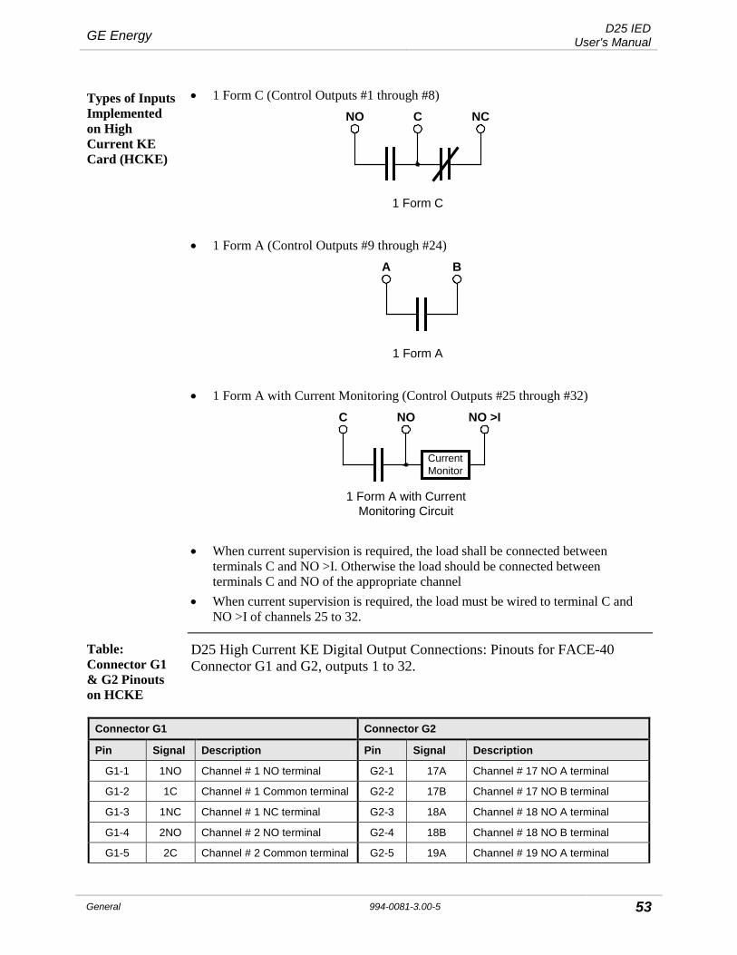
Types of Inputs Implemented on High Current KE Card (HCKE)
• 1 Form C (Control Outputs #1 through #8) NO C NC
1 Form C
• 1 Form A (Control Outputs #9 through #24) A B
1 Form A
• 1 Form A with Current Monitoring (Control Outputs #25 through #32) C NO NO >I
1 Form A with Current Monitoring Circuit
Current Monitor
• When current supervision is required, the load shall be connected between
terminals C and NO >I. Otherwise the load should be connected between terminals C and NO of the appropriate channel
• When current supervision is required, the load must be wired to terminal C and NO >I of channels 25 to 32.
Table: Connector G1 & G2 Pinouts on HCKE
D25 High Current KE Digital Output Connections: Pinouts for FACE-40 Connector G1 and G2, outputs 1 to 32.
Connector G1 Connector G2
Pin Signal Description Pin Signal Description
G1-1 1NO Channel # 1 NO terminal G2-1 17A Channel # 17 NO A terminal
G1-2 1C Channel # 1 Common terminal G2-2 17B Channel # 17 NO B terminal
G1-3 1NC Channel # 1 NC terminal G2-3 18A Channel # 18 NO A terminal
G1-4 2NO Channel # 2 NO terminal G2-4 18B Channel # 18 NO B terminal
G1-5 2C Channel # 2 Common terminal G2-5 19A Channel # 19 NO A terminal

D25 IED User's Manual GE Energy
54 994-0081-3.00-5 General
Connector G1 Connector G2
Pin Signal Description Pin Signal Description
G1-6 2NC Channel # 2 NC terminal G2-6 19B Channel # 19 NO B terminal
G1-7 3NO Channel # 3 NO terminal G2-7 20A Channel # 20 NO A terminal
G1-8 3C Channel # 3 Common terminal G2-8 20B Channel # 20 NO B terminal
G1-9 3NC Channel # 3 NC terminal G2-9 21A Channel # 21 NO A terminal
G1-10 4NO Channel # 4 NO terminal G2-10 21B Channel # 21 NO B terminal
G1-11 4C Channel # 4 Common terminal G2-11 22A Channel # 22 NO A terminal
G1-12 4NC Channel # 4 NC terminal G2-12 22B Channel # 22 NO B terminal
G1-13 5NO Channel # 5 NO terminal G2-13 23A Channel # 23 NO A terminal
G1-14 5C Channel # 5 Common terminal G2-14 23B Channel # 23 NO B terminal
G1-15 5NC Channel # 5 NC terminal G2-15 24A Channel # 24 NO A terminal
G1-16 6NO Channel # 6 NO terminal G2-16 24B Channel # 24 NO B terminal
G1-17 6C Channel # 6 Common terminal G2-17 25C Channel # 25 Common terminal
G1-18 6NC Channel # 6 NC terminal G2-18 25NO Channel # 25 NO terminal
G1-19 7NO Channel # 7 NO terminal G2-19 25NO >I Channel # 25 NO Current monitoring terminal
G1-20 7C Channel # 7 Common terminal G2-20 26NO >I Channel # 26 NO Current monitoring terminal
G1-21 7NC Channel # 7 NC terminal G2-21 26C Channel # 26 Common terminal
G1-22 8NO Channel # 8 NO terminal G2-22 26NO Channel # 26 NO terminal
G1-23 8C Channel # 8 Common terminal G2-23 27C Channel # 27 Common terminal
G1-24 8NC Channel # 8 NC terminal G2-24 27NO Channel # 27 NO terminal
G1-25 9A Channel # 9 NO A terminal G2-25 27NO >I Channel # 27 NO Current monitoring terminal
G1-26 9B Channel # 9 NO B terminal G2-26 28NO >I Channel # 28 NO Current monitoring terminal
G1-27 10A Channel # 10 NO A terminal G2-27 28C Channel # 28 Common terminal
G1-28 10B Channel # 10 NO B terminal G2-28 28NO Channel # 28 NO terminal
G1-29 11A Channel # 11 NO A terminal G2-29 29C Channel # 29 Common terminal
G1-30 11B Channel # 11 NO B terminal G2-30 29NO Channel # 29 NO terminal
G1-31 12A Channel # 12 NO A terminal G2-31 29NO >I Channel # 29 NO Current monitoring terminal
G1-32 12B Channel # 12 NO B terminal G2-32 30NO >I Channel # 30 NO Current monitoring terminal
G1-33 13A Channel # 13 NO A terminal G2-33 30C Channel # 30 Common terminal
G1-34 13B Channel # 13 NO B terminal G2-34 30NO Channel # 30 NO terminal
G1-35 14A Channel # 14 NO A terminal G2-35 31C Channel # 31 Common terminal
G1-36 14B Channel # 14 NO B terminal G2-36 31NO Channel # 31 NO terminal
G1-37 15A Channel # 15 NO A terminal G2-37 31NO >I Channel # 31 NO Current

GE Energy D25 IED User's Manual
General 994-0081-3.00-5 55
Connector G1 Connector G2
Pin Signal Description Pin Signal Description monitoring terminal
G1-38 15B Channel # 15 NO B terminal G2-38 32NO >I Channel # 32 NO Current monitoring terminal
G1-39 16A Channel # 16 NO A terminal G2-39 32C Channel # 32 Common terminal
G1-40 16B Channel # 16 NO B terminal G2-40 32NO Channel # 32 NO terminal
Figure: Connectors G1 & G2 Pinouts Layout
1
DO17
3
DO18
5
DO19
7
DO20
9
DO21
11
DO22
13
DO23
15
DO24
17
DO25
19
DO32
21
DO26
23
DO27
25
DO31
27
DO28
29
DO29
31
DO30
33 35 37 39CMCM CM CM
CMCM CM CM
2 4 6 8 10 12 14 16 18 20 22 24 26 28 30 32 34 36 38 40
Connector G2
1
DO1
3
DO2
5
DO15
7
DO12
9
DO3
11
DO4
13
DO11
15
DO5
17
DO6
19
DO16
21
DO7
23
DO8
25
DO14
27
DO9
29
DO10
31
DO13
33 35 37 39
2 4 6 8 10 12 14 16 18 20 22 24 26 28 30 32 34 36 38 40
Connector G1

D25 IED User's Manual GE Energy
56 994-0081-3.00-5 General
DC Analog Inputs
DC Analog Inputs
• All DC Analog Card options are available with 16 inputs. • The inputs may be voltage or current. • With the exception of the 517-0478 and 517-0479 cards that use adapter
modules, there are no on-board option jumpers; each option requires a different card.
!
Shielding
All inputs should have shield connected at source of signal. Shields can alternately be connected to the auxiliary ground on D25 power supply terminal block. DO NOT ground at both ends of cable.
Table: Digital Counts
Table of typical digital counts stored in the D25 System Point Database representing inputs at several input levels, and scaling settings, for each DC Analog board option:
10% 25% 50% 75% Nom 120%
Inpu
t Opt
ion
+/- 5V .5V 1.25V 2.5V 3.75V 5V 6V
+/- 1 mA .1 mA .25 mA .5 mA .75 mA 1 mA 1.2 mA
+/- 5 mA .5 mA 1.25 mA 2.5 mA 3.75 mA 5 mA 6 mA
+/- 10 mA 1 mA 2.5 mA 5 mA 7.5 mA 10 mA 12 mA
+/- 20 mA 2 mA 4 mA 10 mA 15 mA 20 mA 24 mA
Dis
play
ed
Dig
ital
Cou
nt @ 83.333% Scaling 2731 6826 13653 20479 27306 32767
@ 100% Scaling 3277 8192 16383 24575 32767 >32767
@ 200% Scaling 6553 16383 32767 >32767 >32767 >32767

GE Energy D25 IED User's Manual
General 994-0081-3.00-5 57
DC Analog Inputs, Continued
Table: DC Analog Input Connector Pinout
1 3 5 7 9 11 13 15 17 19 21 23 25 27 29 31 33 35 37 39
2 4 6 8 10 12 14 16 18 20 22 24 26 28 30 32 34 36 38 40
Location of adapters on the module’s PCB for each input: Connector H
Pin # SIGNAL Connector H
Pin # SIGNAL Input Adapter
Location
1 Ain 1+ 2 Ain 1- M1
3 Ain 2+ 4 Ain 2- M2
5 Ain 3+ 6 Ain 3- M3
7 Ain 4+ 8 Ain 4- M4
9 Ain 5+ 10 Ain 5- M5
11 Ain 6+ 12 Ain 6- M6
13 Ain 7+ 14 Ain 7- M7
15 Ain 8+ 16 Ain 8- M8
17 N/C 18 N/C
19 N/C 20 N/C
21 N/C 22 N/C
23 N/C 24 N/C
25 Ain 9+ 26 Ain 9- M9
27 Ain 10+ 28 Ain 10- M10
29 Ain 11+ 30 Ain 11- M11
31 Ain 12+ 32 Ain 12- M12
33 Ain 13+ 34 Ain 13- M13
35 Ain 14+ 36 Ain 14- M14
37 Ain 15+ 38 Ain 15- M15
39 Ain 16+ 40 Ain 16- M16

D25 IED User's Manual GE Energy
58 994-0081-3.00-5 General
AC Analog Inputs
AC Analog Inputs
The D25 accepts up to 15 AC analog inputs, which are grouped into five sets of three each.
The D25 can support virtually any combination of CTs and PTs.
The only restrictions are: • TB1 inputs must be PTs • Each group of 3 transformers must be of the same type
If no AC inputs are specified, AC Input configuration is disabled.
Disabled parameters appear in dark green in the ConfigPro I/O Configuration window
AC Analog Circuit Mapping
A flexible AC input mapping feature, called E-Z Map, is included. • It allows you to configure, for each input of an AC circuit, the physical AC input
that supplies the required signal. • It gives you complete flexibility in wiring the AC inputs and assigning them to
the appropriate circuit inputs.
AC Analog Physical Input Connections
AC INPUTSPT4, PT5, PT6
orCT10, CT11, CT12
TB 2 (1 - 6)
AC INPUTSPT1, PT2, PT3
TB 1 (1 - 6)
PT7, PT8, PT9
TB 3 (1 - 6)
CT4, CT5, CT6TB 4 (1 - 6)
CT7, CT8, CT9TB 5 (1 - 6)
orCT1, CT2, CT3
PT10, PT11, PT12or
PT13, PT14, PT15or

GE Energy D25 IED User's Manual
General 994-0081-3.00-5 59
AC Analog Inputs, Continued
Table: Input Connections
TB1, TB2, TB3, TB4 and TB5 connections.
TB 1 Signal TB 3 Signal TB 5 Signal 1 PT1A 1 PT7A/CT1A 1 PT13A/CT7A
2 PT1B 2 PT7B/CT1B 2 PT13B/CT7B
3 PT2A 3 PT8A/CT2A 3 PT14A/CT8A
4 PT2B 4 PT8B/CT2B 4 PT14B/CT8B
5 PT3A 5 PT9A/CT3A 5 PT15A/CT9A
6 PT3B 6 PT9B/CT3B 6 PT15B/CT9B
TB 2 Signal TB 4 Signal 1 PT4A/CT10A 1 PT10A/CT4A
2 PT4B/CT10B 2 PT10B/CT4B
3 PT5A/CT11A 3 PT11A/CT5A
4 PT5B/CT11B 4 PT11B/CT5B
5 PT6A/CT12A 5 PT12A/CT6A
6 PT6B/CT12B 6 PT12B/CT6B
!
Caution!
Use extreme caution when connecting field wiring to the AC inputs. A D25 can have a wide variety of input options, and there are no obvious indications on the rear of the D25 enclosure to identify the type of inputs installed. Connecting a CT to a voltage input (or vice versa) may cause equipment damage and/or severe injury
Communications Ports
Serial and LAN Options
The D25 is very configurable for communications, offering serial and LAN interface options.
WESMAINT Connector
The WESMAINT II+ connector on the front panel provides a serial interface to access the WESMAINT II+ maintenance facility.
Using WESMAINT you can: • perform local maintenance and diagnostic functionality • download configuration data from the PC-based ConfigPro software • upload diagnostic and operational information from the D25
WESMAINT II+ serial interface supports RS-232 signaling, and operates at a fixed rate of 9600 bps.

D25 IED User's Manual GE Energy
60 994-0081-3.00-5 General
Communications Ports, Continued
Serial WESMAINT Cable
To connect a PC to the D25, use a WESMAINT II+ cable (GE part number 977-0048/96), or equivalent. Attach the 9-pin female jack of the WESMAINT II+ cable to the D25, and the other end of the WESMAINT II+ cable to a PC,
Schematic for this cable:
Terminal - DB-9 Female WESM
N/CRXDTXDN/C
COMN/CN/CN/CN/C
123456789
COM1 D25 MAINT Display Port
The DB-9-F D25 MAINT display interface option provides a local port for optional display devices.
This port located on the back panel provides: • fixed communication parameters • RS-485 interface • 2-wire or 4-wire interface, selected using ConfigPro
− a 2-wire cable is required for 2-wire operation, see cable schematic below.

GE Energy D25 IED User's Manual
General 994-0081-3.00-5 61
Communications Ports, Continued
Table: D25 MAINT Port Pinout
Pinout of the D25 MAINT DB-9 connector.
DB-9 Pin RS-485
1 N/C
2 RX-
3 TX-
4 N/C
5 Com GND
6 N/C
7 TX+
8 RX+
9 EARTH GND
2-Wire RS-485 Cable
Schematic of the cable wiring necessary for 2-Wire RS-485 connection.
Description PIN # PIN # Description
123456789
123456789
N/CData -Data -
N/CCommon Ground
N/CData +Data +
Earth Ground
N/CData -Data -N/CCommon GroundN/CData +Data +Earth Ground
COM2 Universal Time Code (UTC) Port
The Universal Time Code (UTC) port located on the back panel provides a connection to a satellite time-code receiver, or equivalent. • The DB-9-F UTC port can be selected for receive-only RS-232 or RS-422
interface, using ConfigPro. • Supported UTC Port protocols are IRIG-B and Rugby • Communication parameters are determined by the protocol application.
Note Many IRIG-B receivers are available with modulated and/or unmodulated output options. • IRIG-B is received on CTS port. • The input to the UTC port must be unmodulated. • If the unmodulated output of the receiver is a coaxial connection, a converter
will be required to interface the D25.

D25 IED User's Manual GE Energy
62 994-0081-3.00-5 General
Communications Ports, Continued
Table: UTC Port Pinout
How to connect to the UTC Port DB-9 connector for either RS-232 or RS-422 interface.
Note: Pins 7 and 8 are tied together internally.
DB-9 Pin RS-422 Signal RS-232 Signal
1 T_RX+ N/C
2 T_RX- RX
3 N/C N/C
4 N/C N/C
5 COM GND COM GND
6 CLKE+ N/C
7 CLKE- N/C
8 N/C CTS
9 EARTH GND EARTH GND
COM3 and COM4 IED1 and IED2 Serial Ports
Two general-purpose, on-board communication ports are available on the back panel of the D25, and use female DB-9-F style connectors. The IED ports provide: • Variable communication parameters • Optional software flow control • Optional hardware flow control • Out-of-sequence transmission of one byte of data • Support for several I/O timers
Transmission of break characters
Both IED ports RS-232 and RS-485 (for multi-drop applications) are supported on the same physical connector.
Note:, The input resistance 12 KΩ is used for all serial ports in D25 (UTC/IED/XCOM) when configured as RS485. The typical resistance is 24 KΩ, but use 12 KΩ as maximum burden. This is very important for daisy chaining D25s, especially for IRIG-B signals.
IED Serial Ports Options
The COM3 and COM4 serial ports are programmed via ConfigPro for: − RS-232 or RS-485 selection − RS-485 2-Wire / 4-Wire selection
Note: The 2 to 4- Wire selection in ConfigPro’s Device Properties only
affects the internal software control (handshaking) of the interface. It does not change the physical characteristics of the communication ports.

GE Energy D25 IED User's Manual
General 994-0081-3.00-5 63
Communications Ports, Continued
Table: Serial Port Pinouts
Pinouts for COM3 and COM4 serial ports for both RS-232 to RS-485 configurations:
DB-9 Pin RS-232 RS-485
1 CD N/C
2 RX RX-
3 TX TX-
4 N/C N/C
5 GND Com GND
6 N/C N/C
7 RTS TX+
8 CTS RX+
9 EARTH GND EARTH GND
2-Wire RS-485 Cable
Schematic of the cable wiring necessary for 2-Wire RS-485 operation.
Description PIN # PIN # Description
123456789
123456789
N/CData -Data -
N/CCommon Ground
N/CData +Data +
Earth Ground
N/CData -Data -N/CCommon GroundN/CData +Data +Earth Ground

D25 IED User's Manual GE Energy
64 994-0081-3.00-5 General
Communications Ports, Continued
Configuring RS-485 2-Wire
In RS-485 two-wire mode, the RTS line internal to the D25 controls the transmitter (the RTS signal is not propagated on to the serial cable, but is present inside the hardware).
While RTS is active, the transceiver is in transmit mode. The “preamble” and “postamble” timers determine the delay prior to transmission, and the amount of time following transmission that the transmitter remains in control of the RS-485 line.
When the RTS line drops, the RS-485 port is placed back in receive mode until the next time the D25 requests a transmission.
There is a third timer used to configure the amount of time the receiver must be idle before the transmitter can be engaged. Although this timer is configurable, most software applications do not have this timer in their configurations, and thus it is left at its default value.
Control Signal Digital Outputs
There are three digital outputs available through the Auxiliary Controls connector: • System fail output • Radio keying output • Auxiliary control output
The contacts of the relays provide electrical and mechanical isolation for all three signals.
System Fail Output
System Fail Output provides: • Form B (N/C) contact output with a rating of 60 W • Maximum current: 2 A • Maximum voltage across the output: 75 VDC, or 50 VAC • Contact wetting must be supplied from a source external to the D25
This output will be activated during the Power On Self Test (POST) that runs whenever the D25 is reset via software or through cycling of power.
Radio Keying Output
Radio Keying Output provides: • Form A (N/O) contact output with a 60 W rating • Maximum current through the contacts: 2 A • Maximum voltage across the output: 75 VDC, or 50 VAC • Contact wetting must be supplied from a source external to the D25
Radio Keying Output emulates “push-to-talk” whenever the D25 is configured to use radio communications equipment that requires this feature.

GE Energy D25 IED User's Manual
General 994-0081-3.00-5 65
Communications Ports, Continued
Radio Keying Operation
If enabled by configuring jumper JP1 on the IED/UTC card, the Radio Keying Output activates whenever the RTS line of XCOM1 is asserted.
Refer to Configuring Radio Keying Option on Page 115 for details.
Auxiliary Digital Output
Auxiliary Digital Output can be used for control functions when use of a standard digital output is not practical.
The digital output under software control provides: • Form A (N/O) contact output with a rating: 60 W • Maximum current through the contacts: 2 A • Maximum voltage across the output: 75 VDC, or 50 VAC • Contact wetting must be supplied from a source external to the D25
Note When operating the Auxiliary Digital Output using WESMAINT, Only On or Off (latch) commands are supported.
Attempting any other mode of operation will result in an error code being displayed.
Serial XCOM Interfaces
If an Ethernet or a Serial XCOM external communication module is installed in the D25, the XCOM interfaces are designated COM5 and COM6, respectively.
Serial XCOM Connection
The Serial XCOM (part numbers 580-0991 and special order 580-0933) cards have two DB-9-F interfaces, labeled XCOM1 and XCOM2.
They both have these characteristics: • External power connection • Programmed via ConfigPro for:
− RS-232 or RS-485 − RS-485 2-Wire or 4-Wire
Note: The 2 to 4-Wire wire selection in ConfigPro’s Device Properties
only affects the internal software control (handshaking) of the interface. It does not change the physical characteristics of the ports.

D25 IED User's Manual GE Energy
66 994-0081-3.00-5 General
Communications Ports, Continued
Table: Serial XCOM Port Pinouts
Pinouts for COM5 and COM6 serial ports for both RS-232 and RS-485 configurations:
DB-9 Pin RS-232 RS-485
1 CD N/C
2 RX RX-
3 TX TX-
4 (+12V) (+12V)
5 GND Com GND
6 (-12V) (-12V)
7 RTS TX+
8 CTS RX+
9 EARTH GND EARTH GND
2-Wire RS-485 Cable
Schematic for the cable wiring necessary for 2-Wire RS-485 operation. Description PIN # PIN # Description
123456789
123456789
N/CData -Data -
N/CCommon Ground
N/CData +Data +
Earth Ground
N/CData -Data -N/CCommon GroundN/CData +Data +Earth Ground
External ±12 Volt Supply
The XCOM card part number 580-0931 is equipped with a 3-pin terminal (Phoenix) block, where the power for modems attached to the DB-9 connectors can be externally supplied.
1
6
5 41
6
5 4 3 2 1
GND -12V +12V
External Power
Note The power connections are labeled ±12 V, and can be used to provide a variety of AC or DC voltages.
Use care not to exceed connector or cable specifications.

GE Energy D25 IED User's Manual
General 994-0081-3.00-5 67
Communications Ports, Continued
!
Caution
580-0933 Special Order
Only
The 580-0933 type of serial XCOM is available only through special order.
It provides power for external communication devices, such as modems, from the D25 internal power supply. This violates the isolation specifications of the card, and can lead to two problems, if not accounted for: • an external surge of voltage, such as a lightning strike, can be passed from a
modem into the D25 internal circuitry where damage may occur • inadvertent connection of power to the card’s external 3-pin terminal block may
cause damage to the D25 power system
Difference Between IED and Serial XCOM Ports
The XCOM ports provide the same functionality as the IED Ports, with this difference: • XCOM ports run at a lower priority than the IED ports. It is therefore most
efficient to put the heaviest communication on the XCOM ports.
Note If you place the heaviest traffic on the IED ports, the higher priority IED ports will often delay servicing of the XCOM ports.
Constant high-volume traffic on the IED ports can cause the XCOM ports to lose data. By placing the lower traffic connections on the IED ports, you ensure that XCOM ports always get serviced in a timely manner. Heavier traffic on the XCOM ports will be interrupted only momentarily (and within the buffering ability of the XCOM card) by small bursts on the higher priority IED ports.
Connecting Ethernet XCOM Interfaces
Three variations of Ethernet / 802.3 XCOM cards are available: • 10BASE2 (obsolete and available as Special Order – see Product Bulletin
PRBT-0252) • 10BASE-T • 10BASE-FL
All have dual interfaces, labeled XCOM1 and XCOM2. Refer to page Error! Bookmark not defined. for information about jumper
options.
10BASE2 Card Connections & Indicators
• Cable: “Thin” Coax RG-58 • Connection is BNC-type. • First and last units on coaxial cable need 50Ω termination
Note: The 10BASE2 XCOM card has no LED indicators on its back panel.
This option is obsolete and available as Special Order – see Product Bulletin PRBT-0252)

D25 IED User's Manual GE Energy
68 994-0081-3.00-5 General
Communications Ports, Continued
10BASE-T Card Connections & Indicators
• Unshielded Twisted-Pair (UTP) wire • RJ-type connectors used • Either a point-to-point or star network topology using multi-port repeater, or
Hub.
The 10BASE-T module has six LEDs on the back panel. LED Function Comments
RCV Transceiver is receiving Turns on when connection is made, indicating receiver is unsquelched.
Blinks when traffic is received.
XMT Transceiver is transmitting
Flashes only when transmitting
JAB Network Jabber status Normally off. Transmitter is disabled when on.
CLS Collision is taking place on network
Indicates a JAM signal is being broadcast on LAN.
POL Receive Polarity Off when receive polarity is correct.
LTF Link Test Fail Low signal level received. Both the transmitter and receiver are disabled.
10BASE-FL Card Connections & Indicators
• Fiber-optic media • ST-type connectors.
The 10BASE-FL module has six LEDs on the back panel.
LED Function Comments
RCV Transceiver is receiving Blinks when traffic is received
XMT Transceiver is transmitting
Flashes only when transmitting
PWR Power is applied Normally on
JAB Network Jabber status Transmitter is disabled when on
CLS Collision is taking place on network
Indicates a JAM signal is being broadcast on LAN
LMO Link Monitor Indicates low light level received
GE Energy D25 IED User's Manual
General 994-0081-3.00-5 69
Chapter 4: Powering-up and Testing
Power-up and test the D25
Once you have completed all field wiring and communication connections and the necessary hardware configuration, the next step is to power-up the D25 and verify that it is functioning properly.
Use this section of the guide to prepare for powering-up and learn how to correctly perform the power-up and other tests: • What is needed to test: WESMAINT II+, 68K Monitor and ConfigPro • How to power-up the D25 and conduct the BOOT Test: Power On Self-Test • Digital Input Verification Test • Digital Output Verification Test • DC Analog Input Test • AC Voltage and Current Input Test
If power-up and test reveals that the D25 is not functioning properly due to software malfunction and you need to download code and configuration files to the FLASH memory, see D25 Software.
Note Before any of the tests and procedures in this section can be performed, a valid configuration file must be loaded into the D25’s NVRAM.
If you have replaced the main board of the D25, then you need to restore the configuration file so that verification tests can be performed.
If you need help restoring your configuration file, refer to the ConfigPro On Line Help.
Testing Utilities
Testing Utilities The following utilities are used to configure and test the D25: • WESMAINT II+ • 68K Monitor • ConfigPro Configuration system
There is some functional overlap between these components.
WESMAINT II+
Each operational D25 unit includes a WESMAINT II+ facility that allows you to go on-line with the D25 to examine the database, applications and communications, and to manipulate the data.
For example, the state of a digital input data can be examined, or a digital output forced on or off.
D25 IED User's Manual GE Energy
70 994-0081-3.00-5 General
Testing Utilities, Continued
Accessing WESMAINT II+ Using a Terminal
You can use a VT100-compatible terminal or a terminal emulation program to directly access the WESMAINT II+ facility. Examples of suitable terminal emulation programs are: • The third party terminal emulation software included on the ConfigPro CD • The ConfigPro configuration system’s Terminal Emulator
If your PC (or similar platform) has a TELNET terminal emulation software package, it can be used to connect to the D25 through an Ethernet network link. Note: For further information about using WESMAINT II+ software to
perform any of the test procedures in this section, refer to the WESMAINT II+ User’s Guide.
Note Microsoft® Windows® HyperTerminal can be used for terminal emulation but it is NOT recommended because code and configuration file download time is considerably increased.
68K Monitor The 68K Monitor is a debugging and diagnostics tool that is accessible in two ways: • As a menu selection in WESMAINT II+. • Upon start-up of a D25 that has not been previously configured.
Note: For further information about using the 68K Monitor, refer to the
68K Monitor User’s Guide.
ConfigPro The ConfigPro Configuration System is used to define the operational parameters of the D25. ConfigPro can be used to download configuration files to the D25 through a serial connection, or through the optional Ethernet TELNET connection available to Windows users. Note: For further information about ConfigPro, refer to the ConfigPro On
Line Help.

GE Energy D25 IED User's Manual
General 994-0081-3.00-5 71
Boot Up
Procedure: BOOT Test: Power On Self Test (POST)
The software installed at the factory includes a Power On Self-Test (POST) process. This test, which you can initiate before the D25 is installed or connected remotely, verifies that all circuitry is responding and all internal connections are firmly in place.
You may need to do this after maintenance work has been carried out, such as a board replacement or upgrade.
Steps to verify the POST process:
Step Action
1 Move the CONTROLS switch on the front panel of the D25 to the REMOTE position.
2 Verify that power cable is properly connected to the D25, and the proper power is available. See Power Supply for power connection details.
3 Locate the power switch on the back of the D25, and toggle it to the ON position. Results: The POWER indicator, a green LED on the front panel
lights when power to the D25 is turned on.
System Diagnostics
The D25 automatically boots, conducting a series of self-diagnostic tests as soon as the power is turned on. Note: If the D25 fails to function, it might have sustained internal damage
during shipping. Contact GE Energy for assistance.
Note The LOCAL LED, POWER LED and RUN LED all light up during the self-diagnostic sequence.
See Front Panel Indicators for more information on LEDs on startup.
Diagnostics Completed
Self-diagnostic testing is complete when: • The Software Application list appears on the PC monitor, if connected • If a control card is installed, the REMOTE indicator LED lights up, and the
LOCAL LED turns off.

D25 IED User's Manual GE Energy
72 994-0081-3.00-5 General
Using WESMAINT
On-Line Start-up Test
When the D25 is powered-up or restarted, internal processes perform a series of routines, starting with self-tests, followed by the spawning of all the software applications that reside in the unit’s memory.
Many of these processes will output progress messages to the 68K monitor, as they are performed. Having a terminal set up to view these start-up messages can provide useful information about the operational status of the unit.
Note Terminal emulation software is not part of the D25 system, but terminal software, such as ConfigPro’s Terminal Emulator, can be used for viewing system messages.
For complete instructions about using the emulation software in your stand-alone PC or laptop, refer to the documentation provided with the software.
Procedure: Setup Terminal for WESMAINT
Steps to setup a PC to act as a WESMAINT II+ terminal.
Step Action
1 Open the VT100 compatible terminal emulation software you are going to use.
2 Verify (or set) terminal communications settings as follows: • Data Rate
• Data Bits
• Stop Bits
• Parity
• Flow Control
• Connector settings
9600 bps
8
1
None
Xon/Xoff (software)
(COM1, COM2) as required by the computer being used
Results: Your terminal emulator settings are now configured.

GE Energy D25 IED User's Manual
General 994-0081-3.00-5 73
Using WESMAINT, Continued
Procedure: Connect to the WESMAINT
Step Action
1 Connect a WESMAINT II+ cable to the female DB-9 WESMAINT II+ port on the front panel of the D25.
2 Attach the other end of the WESMAINT II+ cable to the selected serial communications port of the PC or terminal.
D25 Hardware Setup
3 Move the CONTROLS switch on the front panel of the D25 to the REMOTE position.
4 Verify that power cable is properly connected to the D25, and the proper power is available. See Power Supply above.
5 Locate the power switch on the back of the D25, and toggle it to the ON position. Results: The POWER indicator, a green LED on the front panel
lights when power to the D25 is turned on.
6 Monitor the terminal display. Results: A series of text scripts display as the POST routines are
performed. If the text does not display, check connections and repeat this procedure.
Note The D25 automatically boots as soon as the power is turned on. If the D25 fails to function, it might have sustained internal damage during shipping. Contact GE Energy for assistance.
WESMAINT CONNECTOR

D25 IED User's Manual GE Energy
74 994-0081-3.00-5 General
Testing Hardware I/O Points
Testing Hardware I/O Points
To test I/O points: • Login to WESMAINT • Navigate to the specific WESMAINT display for the type of points you want to
test • Follow the instructions given below for testing specific types of points
!
Data Points
The Plant I/O software application version in the D25’s firmware determines the quantity and relative position of data points in the System Point Database
The actual point number that you want to test can be determined by: • Viewing the point descriptions that are displayed in WESMAINT • Referring to the ConfigPro configuration tables for this specific D25. Note: Actual point descriptions displayed in WESMAINT depend on
changes made to the point descriptions in the running configuration file.
Procedure: Login to WESMAINT
When the POST is complete, login to WESMAINT to test I/O points.
Step Action
1 Press ENTER on the PC keyboard Results: The Welcome screen appears, including a Login prompt.
Note: If the Welcome banner does not appear, and only a <D25S prompt is displayed, a valid code and/or configuration file is not loaded into the D25’s memory. Stop this procedure and review procedures for restoring files: see D25 Software.
2 Type the User Name: westronic and Press ENTER. (*)
3 Type the Password: rd and Press ENTER. (*) Results: The WESMAINT II+ Main Menu appears.
4 If a time-out occurs, press ENTER again, to return to login prompt.
WESMAINT Tips
• User name and password shown are factory defaults. If you cannot log in, contact your system administrator to obtain new user name and password.
• To select an option from the menus, use the up and down arrow keys to highlight and item and press ENTER, or type the menu item number.
• Press CTRL+L at any time to log out of WESMAINT II+. • For further information, see the WESMAINT II+ User’s Guide

GE Energy D25 IED User's Manual
General 994-0081-3.00-5 75
Testing Hardware I/O Points, Continued
Digital Input Verification Test
Testing Digital Inputs: Digital input changes are displayed in WESMAINT.
Procedure: Verify Digital Input
To conduct this test the code and configuration file must be downloaded to the D25’s FLASH memory.
Note: The following procedure assumes that the digital inputs for the D25 are configured to use supplied wetting. Refer to page 26 for configuration information.
From the WESMAINT II+ Main Menu:
Step Action
1 On the Main Menu, type 1 — System Data Display.
Results: The System Data Menu appears.
2 On the System Data Menu, type 1 — Digital Input Display. Results: The point numbers and (optionally) point descriptions
appear on the WESMAINT II+ display.
3 Use the arrow keys to move up or down to highlight the desired point number.
4 Use a wire jumper to short out the desired input point, and verify that WESMAINT shows that the point status has changed to On.
5 Go back to Step 3 and repeat the test as necessary to test other available digital points.
Navigating through screens
• Press N to move to the Next page. • Press P to move to the Previous page. • Press ESC to back up to the previous menu level.

D25 IED User's Manual GE Energy
76 994-0081-3.00-5 General
Testing Hardware I/O Points, Continued
Digital Output Verification Test
Testing Digital Outputs: You can force digital outputs from WESMAINT.
!
Caution!
Use caution when testing digital output points that are connected to external equipment. This test may damage external devices, such as relays or reclosers, and may injure personnel.
Procedure: Verify Digital Output
To conduct this test the code and configuration file must be downloaded to the D25’s FLASH memory.
From the WESMAINT II+ Main Menu:
Step Action
1 On the Main Menu, type 1 — System Data Display.
Results: The System Data Menu appears.
2 On the System Data Menu, type 2 — Digital Output Display. Results: The point numbers and (optionally) point descriptions
appear on the WESMAINT II+ display.
3 Use the arrow keys to move up or down to highlight the desired point number. Results: The cursor should now be flashing on the specified point
number.
4 Press CTRL+F when you are ready to force-change the state of the digital output point.
Extra Security
5 At the Password prompt, type control (*) and press ENTER. Results: The Digital Output Force Display appears.
6 Press CTRL+U to change (update) the relay state.

GE Energy D25 IED User's Manual
General 994-0081-3.00-5 77
Testing Hardware I/O Points, Continued
Procedure: Verify Digital Output (continued)
Step Action
7 Press the SPACE BAR to select Pulse and press ENTER
8 In the Off time field, type 500 and press ENTER
9 In the On time field, type 500 and press ENTER
10 In the Repeat Command field, type 10 and press ENTER twice Results: Listen carefully for an audible click of the point relay.
The test is considered successful if the relays click when forced.
Notes • The number of times that a control will operate is N+1, where N is the number of repeats entered in the Repeat command field
Examples: For a single operation (i.e., no repeats) type 0; for two operations, type 1
Test Failure No error message appears in WESMAINT if the test fails. If relays do not operate:
1. Ensure that the CONTROLS switch is in the REMOTE position.
2. Reboot the D25, and repeat the procedure.
3. Call GE Energy for assistance.
Repeat Test To repeat the test sequence, press CTRL+U. Press ENTER.
Values entered for the previous test are retained until you exit the menu.
Test Next Point To test another point, use the up or down arrow keys to cycle through points, then press CTRL+U to repeat test.
Note The same test procedure can be applied when testing the Aux. Output.

D25 IED User's Manual GE Energy
78 994-0081-3.00-5 General
Testing Hardware I/O Points, Continued
DC Analog Input Test
Testing DC Analog Inputs: the first part of this test verifies that the internal Analog References are operating within the nominal range.
Analog Input changes are displayed in WESMAINT.
Procedure: Verify Analog Input
To conduct this test the code and configuration file must be downloaded to the D25’s FLASH memory.
First, check the Analog Reference values. From the WESMAINT Main Menu:
Step Action
1 On the Main Menu, type 1 — System Data Display.
Results: The System Data Menu appears.
2 On the System Data Menu, use the up and down arrow keys, or type the menu number 3, to select Analog Input Display, then press ENTER. Results: The point numbers and (optionally) point descriptions
appear on the WESMAINT II+ display.
3 Use the arrow keys to move up or down to highlight a D25 Plant I/O Analog Reference point.
4 Verify that the points display a value close to the values shown in this table:
Table: Analog Reference Values
Use this table to verify the DC analog reference values.
Description Nominal Value
Positive DC Analog Reference 4095 (+/- 230)
Negative DC Analog Reference -4095 (+/- 230)
Zero DC Analog Reference 0 (+/- 164)
Notes • These reference values are monitored by D25 software. • When the D25 software detects an invalid DC analog reference, it sets the value
of the field DC analog points to zero and sets the over-range attribute on those points.

GE Energy D25 IED User's Manual
General 994-0081-3.00-5 79
Testing Hardware I/O Points, Continued
Procedure: Verify Analog Input (cont’d)
On the Analog Input Display:
Step Action
5 Press CTRL+G and type the number of the first input point (if known), or use the up and down arrow keys to scroll to the desired analog input point.
6 Connect one end of testing leads to a calibrated voltage or current source.
7 Connect the other end of the leads to the first analog input point on the DC analog input termination.
8 Using the following table as a reference, adjust input voltage or current to these levels: • 0% of full scale • 5% of full scale • 95% of full scale
9 Verify that the values displayed in WESMAINT fall near the values shown in the following table.
10 Go back to Step 5 and repeat as desired for other points on the DC analog input termination.
Table: DC Analog Input Values
Use this table to verify the DC analog input values.
DC Input Option
0% FS Nominal Displayed
Count
5% FS Nominal Displayed
Count
95% FS Nominal Displayed
Count
5 V 0 V
0
0.25V
1638
4.75V
31129
1 mA 0 mA 0.05 mA 0.95 mA
5 mA 0 mA 0.25 mA 4.75 mA
10 mA 0 mA 0.50 mA 9.5 mA
20 mA 0 mA 1.0 mA 19 mA
Notes • Full-scale for all displayed DC analogs is represented by a range of 32767 to -32768 (15-bit plus sign value).
• Full-scale of DC Voltage and Current measurements is the nominal value.

D25 IED User's Manual GE Energy
80 994-0081-3.00-5 General
Testing Hardware I/O Points, Continued
AC Voltage and Current Input Test
Testing AC Analog Inputs: Changes are displayed in WESMAINT.
Procedure: Test AC Voltage and Current Input
To conduct this test, the code and configuration file must be downloaded to the D25’s FLASH memory.
Note: The actual point descriptions displayed in WESMAINT depend on the circuit configuration (i.e., line-to-line or line-to-neutral, etc.) and any changes made to the point descriptions in the running configuration file.
To verify that the correct AC voltage and current values are displayed in WESMAINT:
Step Action
1 Navigate to the WESMAINT II+ System Data Menu.
2 On the System Data Menu, type 3 — Analog Input Display.
PT input test
3 Press the down arrow key to scroll to the point named RMS Voltage Phase A Circuit 1. (see Note: above)
4 Apply nominal voltage to the first AC voltage input termination points.
5 Verify that the measured counts are close to their nominal value.
6 Go back to Step 3 and repeat for other points on the AC voltage (PT) input termination.
CT input test
7 When voltage input tests are complete, press the down arrow key to scroll to the point named RMS Current Phase A Circuit 1
8 Apply nominal current to the first AC current input termination points.
9 Verify that the measured counts are close to their nominal value.
10 Go back to Step 7 and repeat for other points on the AC current (CT) input termination.

GE Energy D25 IED User's Manual
General 994-0081-3.00-5 81
Testing Hardware I/O Points, Continued
Note Only points used by the Plant I/O, based on downloaded configuration, will display values.
Unused points will be off-line.
Table: Reference Values
Use this table as example references for the AC analog input verification test. Note: Nominal values can be determined by reviewing ConfigPro’s P097
Plant I/O configuration tables for this device.
Point Description Nominal Value
Voltage Phase A Circuit 1 13107
Voltage Phase B Circuit 1 13107
Voltage Phase C Circuit 1 13107
Current Phase A Circuit 1 2048
Current Phase B Circuit 1 2048
Current Phase C Circuit 1 2048
Neutral Current Circuit 1 2048
Voltage Phase A-B Circuit 2 13107
Voltage Phase B-C Circuit 2 13107
Current Phase A-B Circuit 2 2048
Current Phase B-C Circuit 2 2048
Neutral Current Circuit 2 2048
Notes • Full-scale for all AC analog values displayed in WESMAINT is represented by a count of 32767 (15-bit plus sign value).
• Full-scale of voltage measurements is 2.5 times the nominal value. • Full-scale of current measurements is 16 times the nominal value. • For more detailed information, refer to the D25 Plant I/O Subsystem
Configuration Guide.

D25 IED User's Manual GE Energy
82 994-0081-3.00-5 General
Chapter 5: Configuring the D25 Software
D25 Software
D25 Software The D25 is factory configured and tested. It contains all software required to be a fully functional system and upload and download configuration databases.
You may need to download configuration files to your D25: • If the D25 has performed self-diagnostics and determined that the FLASH
memory is either erased or corrupted • Other test messages indicate that the FLASH memory has been erased or
corrupted • After maintenance or replacement work which has deleted the FLASH code files
Use this section as a guide for: • An overview of the software and software tools you will use • Information and procedures for maintaining code and configuration files • How to test the functionality of the inputs and outputs controlled by the D25
Plant I/O • A discussion of code and configuration files • How to remove configuration files from memory • How to install new or replacement code files using a serial connection
Overview The D25 system software consists of two distinct components:
1. Base System
2. Applications
Base System Software
The Base System Software resident in the D25 provides a consistent, stable operating environment for the Applications that provide specific functionality to the D25.
The Base System Software consists of: • Software that is resident on the BootROM • Base Applications that are required for the operation of the hardware.

GE Energy D25 IED User's Manual
General 994-0081-3.00-5 83
D25 Software, Continued
D25 BootROM BootROM software is stored in replaceable EPROM. The BootROM contains: • pSOS operating system software • Device drivers to interface the pSOS with the system hardware and software • Diagnostic tests required to verify the integrity of the D25 • The monitor interface for examining the system in a non-operational mode • Startup code that verifies and initializes the application software • A stand-alone system for low-level maintenance and troubleshooting.
− All of the code in the D25 BootROM is duplicated in the standard Base application load. When the D25 is operating the BootROM applications, it does not refer to the applications in the FLASH code, and vice versa.
Base Applications
Standard D25 Base Applications that are present in every D25 are: • WIN: the system database manager • WESMAINT II+: allows an operator to examine and control data locally on the
D25 system • 68K Monitor: low-level system maintenance and diagnostic tools
WIN The WESDAC Interface Node (WIN) is the database manager for the D25’s System Point Database.
The System Point Database is central to the D25 software system All data flowing through the unit is stored in the WIN before passing on to its destination.
WESMAINT II+
The WESMAINT II+ is the D25’s primary maintenance and diagnostic tool.
WESMAINT can be accessed in three ways:
1. Via the serial port on the front of the D25
2. Through a modem or other serial connection to a programmed COM port on the rear of the D25
3. Over a LAN or serial PPP connection, as a TELNET session from a remote network station
See above: WESMAINT II+, Accessing WESMAINT II+ Using a Terminal.
Front Panel LCD Software Configuration
A D25 fitted with an LCD panel must be equipped with the Data Display DTA (B062) application software to communicate with the panel.
Using Config Pro, specific D25 database input points are mapped into this software.

D25 IED User's Manual GE Energy
84 994-0081-3.00-5 General
Front Pane Graphic Display Panel Software Configuration
A D25 fitted with a GDP must be equipped with Modbus DPA (A059) or DNP 3.0 DPA application software to communicate with the GDP. Using Config Pro, some or all of the D25’s database points are mapped into this communication software.
Inside the GDP, these points are then mapped into the GDP graphic objects. Note: Please contact GE for assistance in order to learn more about the
configuration tools and settings available for GDP.
GE Energy D25 IED User's Manual
General 994-0081-3.00-5 85
Downloading a Configuration
The D25’s 68K Monitor
The 68K Monitor, available through WESMAINT, contains diagnostic tools that allow access to system level functions.
The D25’s Monitors are resident in both the BootROM and the application bank (Flash memory): • When operating from BootROM, the prompt that appears is D25S>
− This mode is accessed only while the D25 is in a maintenance state − Forcing a D25 into this monitor will terminate any applications that are
running • When operating from Flash, the prompt that appears is D25A>.
− This is the normal mode of operation, and can be accessed via WESMAINT at any time while the unit is operational
!
Using 68K Monitor
Using the Monitor requires detailed knowledge of the D25 architecture and functionality — both alone and as part of a larger system.
Refer to the 68K Monitor User’s Guide for complete instructions about command usage and availability.

D25 IED User's Manual GE Energy
86 994-0081-3.00-5 General
Downloading a Configuration, Continued
About Code and Configuration Files
All D25 units require two distinctly different files to be loaded into memory before the unit will become operational: • Code File
− This file is created using GE Energy’ Software Development System, and is used to define the applications that can be used in a D25 system.
• Configuration File − This file is generated using the ConfigPro configuration tool, and is used to
enable and configure the operational characteristics of the applications defined by the code file.
!
Extremely Important
The Code File and the Configuration File loaded into any D25 must match perfectly: • The applications and application versions used in the configuration files created
using ConfigPro must be the same as the applications and application versions used to make the code file.
Any differences between the applications in the code and configuration files may result in erratic or unpredictable behavior of the D25
How can Configuration and Code File Mismatch Happen?
Here are some common ways that this can occur: 1. The wrong configuration file is accidentally downloaded into a unit. For
example, based on a D25 that has a different code file installed. This can happen either: − Through a local serial ConfigPro download, or − Remotely over a LAN connection using TELNET or BootP
2. A code file is downloaded that does not match the configuration file that is presently resident in the D25’s NVRAM
3. Either the code file or the configuration file has been corrupted, either before or during download
How can Mismatch be Prevented?
1. Wrong configuration file: usually a result of operator or BootP Server configuration error, and can only be prevented by exercising care.
2. Mismatched code file: can be prevented by erasing any configuration file that may be resident in NVRAM before downloading a new code file.
3. Corruption: may require the regeneration of one or both files, and re-downloading.

GE Energy D25 IED User's Manual
General 994-0081-3.00-5 87
Downloading a Configuration, Continued
What Happens when the Files do not Match?
A mismatch error between Code and Configuration files causes the D25 to reboot.
How Does the D25 React to This type of Error?
The D25’s base system performs this procedure after each reboot:
1. Every time the D25 is rebooted, a counter is incremented.
2. If the D25 runs for 2 minutes without a reboot, this counter is cleared.
3. If the counter ever reaches 20, the base system invalidates the configuration by writing "KILL" into the configuration file without recalculating the file’s CRC.
4. The base system then forces a system reset.
5. When the unit comes back up, the base system detects a configuration that is now invalid and creates a default configuration instead (or loads a stored back-up configuration, if it is available in memory).
Why is This Done?
This process is designed to protect systems that have fatal errors that cause the system to reset before the user can get into WESMAINT to fix the problem
While a user can always directly default the configuration by pressing <ESC> during the start-up sequence, this only works if the customer is physically present and connected to the WESMAINT port.
Since the D25 has the ability to receive files remotely over a LAN, the problem may occur when a user is downloading remotely and logging in over TELNET. An error that causes the system to constantly reboot could potentially continue forever, filling up NVRAM with many error messages. This process enables the D25 to eventually settle down on its own.
When to Erase a Configuration
Rule: If the code file is not exactly the same as the one that was in use before the download, then erase a configuration file from the D25’s NVRAM before downloading a new code file into FLASH memory.

D25 IED User's Manual GE Energy
88 994-0081-3.00-5 General
Downloading a Configuration, Continued
Procedures: Ways to erase a Configuration
There are three ways to erase a configuration file from the D25’s NVRAM:
One Way
Step Action
1. Reboot the D25, and while it is starting, press the ESCAPE key. Results: This message pops-up: Are you sure you wish to generate a default configuration [y\n]?
2. Type Y and press ENTER Results: The configuration will now be defaulted.
Second Way
Step Action
1. With a terminal connected to the D25’s monitor, type DHW (Display HardWare) or SI (System Information) on older units. Results: A listing of information, including the start address and
size of the NVRAM used for the configuration file is displayed. The NVRAM end address can be calculated by adding the NVRAM size to the NVRAM start address.
2. Type F 00 <NVRAM Start Address> <NVRAM End Address> and press ENTER Results: The specified range of NVRAM will be filled with 0s,
erasing any configuration file.
Third Way
Step Action
1. With the power removed from the D25, remove the battery on the WESDAC board for at least 15 minutes.
Refer to page 102, Battery Replacement for a detailed procedure for removing and replacing batteries.
D25 Locked-up?
Use the Third Way to unlock a D25 that has been locked up through a code/configuration file mismatch.

GE Energy D25 IED User's Manual
General 994-0081-3.00-5 89
Downloading a Configuration, Continued
Downloading Code Files: When to Download
There are two reasons for downloading firmware code files: • If the D25 has performed self-diagnostics and determined that the FLASH
memory is either erased or corrupt, then it will display the D25S> prompt on the system monitor when it requires code files to be downloaded.
• If the D25 software program features need to be changed or upgraded, the existing FLASH memory can be erased, and new code downloaded.
Choice of Three Processes
Three techniques for programming the FLASH memory are available. The technique to use depends on system options and network type.
The choices are:
1. A serial connection from a PC to the WESMAINT port, using third-party communications software. − This procedure is described below.
2. Use ConfigPro, either via a serial connection to the WESMAINT port, or via Ethernet using a TELNET and TFTP procedure. − These options are described in the ConfigPro On Line Help.
3. A third-party parallel port adapter and software utility is available to connect directly to the BDM port on the D25 WESDAC Board, which permits very quick downloads. − This is the procedure used during manufacture of the D25.
Insufficient Memory
When a new code image is downloaded into the FLASH memory of a D25, the amount of memory reserved for the configuration’s data region, also referred to as the “Base” region, may not be large enough.
If this occurs, then the D25 locks-up and a message similar to this will be displayed:
The configuration’s data region overlaps the current Configuration Header (NVHEADER). Relocate the Configuration Header / NVRAM to <address>, or set data size to <size> and re-download. Application will NOT be started.
If this message appears: • Unlock the D25 • Increase the base region memory. Consult the ConfigPro Online Help for how to
set the D25’s Device Properties to increase the Base Region size.
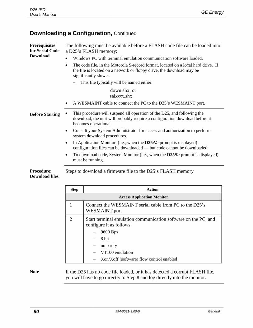
D25 IED User's Manual GE Energy
90 994-0081-3.00-5 General
Downloading a Configuration, Continued
Prerequisites for Serial Code Download
The following must be available before a FLASH code file can be loaded into a D25’s FLASH memory: • Windows PC with terminal emulation communication software loaded. • The code file, in the Motorola S-record format, located on a local hard drive. If
the file is located on a network or floppy drive, the download may be significantly slower. − This file typically will be named either:
down.shx, or salxxxx.shx • A WESMAINT cable to connect the PC to the D25’s WESMAINT port.
Before Starting • This procedure will suspend all operation of the D25, and following the download, the unit will probably require a configuration download before it becomes operational.
• Consult your System Administrator for access and authorization to perform system download procedures.
• In Application Monitor, (i.e., when the D25A> prompt is displayed) configuration files can be downloaded — but code cannot be downloaded.
• To download code, System Monitor (i.e., when the D25S> prompt is displayed) must be running.
Procedure: Download files
Steps to download a firmware file to the D25’s FLASH memory
Step Action
Access Application Monitor
1 Connect the WESMAINT serial cable from PC to the D25’s WESMAINT port
2 Start terminal emulation communication software on the PC, and configure it as follows:
− 9600 Bps − 8 bit − no parity − VT100 emulation − Xon/Xoff (software) flow control enabled
Note If the D25 has no code file loaded, or it has detected a corrupt FLASH file, you will have to go directly to Step 8 and log directly into the monitor.

GE Energy D25 IED User's Manual
General 994-0081-3.00-5 91
Downloading a Configuration, Continued
Procedure: Download Files (continued)
Step Action
Launch System Monitor
3 Log into WESMAINT.
4 Select option 2, System Functions
5 Select option 3, 68K Monitor Result: The D25A> prompt appears, indicating that the
Application Monitor is running.
6 At the D25A> prompt type rtb ENTER For other available commands type help ENTER
7 At the Return to the BootROM Operating System? (yes/no) prompt, type yes ENTER Note: The monitor is not case-sensitive, but Y is not acceptable.
Result: The system restarts.
!
Warning
Invoking the Return to BootROM command will completely disable the system.
Login to System Monitor
8 After the restart is complete, press ENTER. Result: The Login: prompt displays.
9 Type the login name harris ENTER and password rd ENTER. Result: The system performs self-diagnostics to ascertain whether
any Flash EPROM memory is in use. The D25S> prompt appears, indicating that the System Monitor is running.
Clear FLASH EPROM
10 Type erase and press ENTER (not case-sensitive) Note: The recommended procedure is to clear Flash EPROM
memory — no matter what the system check reveals.
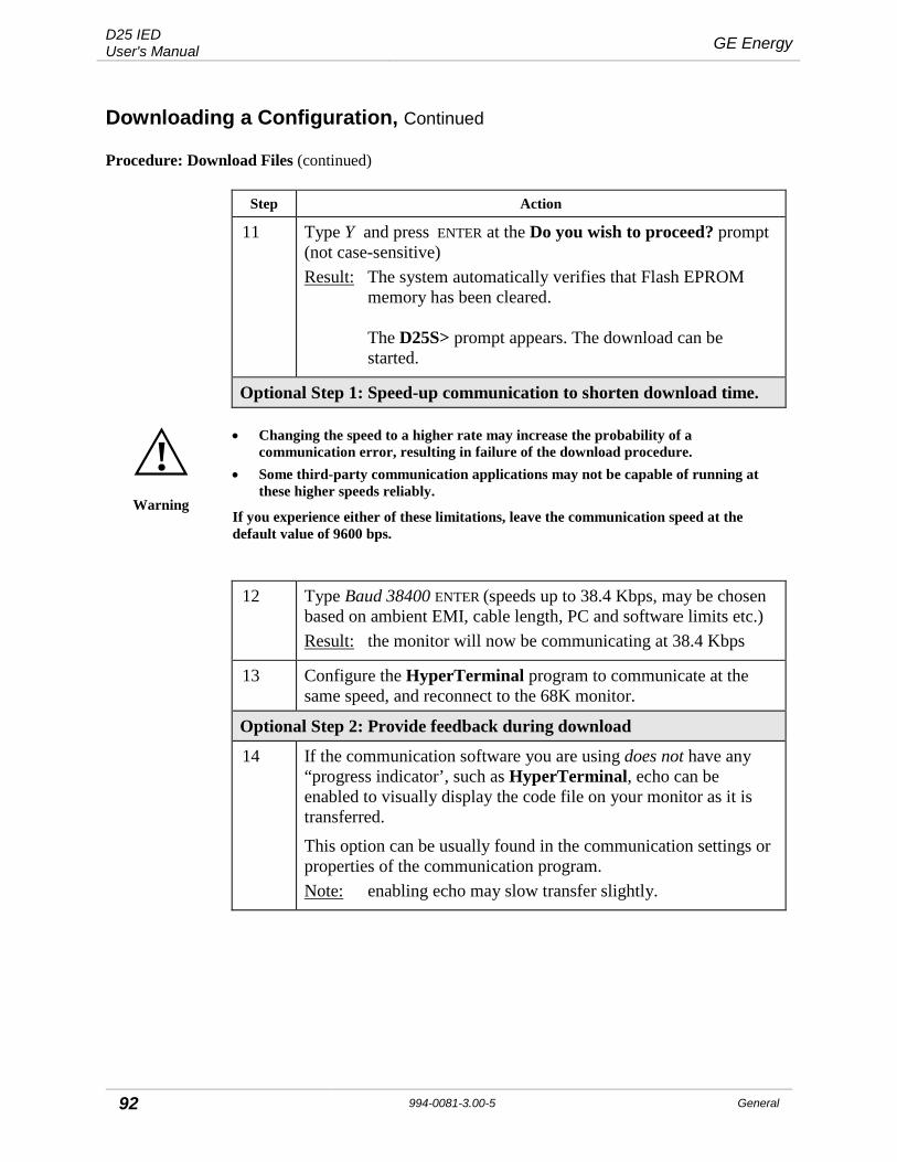
D25 IED User's Manual GE Energy
92 994-0081-3.00-5 General
Downloading a Configuration, Continued
Procedure: Download Files (continued)
Step Action
11 Type Y and press ENTER at the Do you wish to proceed? prompt (not case-sensitive) Result: The system automatically verifies that Flash EPROM
memory has been cleared. The D25S> prompt appears. The download can be started.
Optional Step 1: Speed-up communication to shorten download time.
!
Warning
• Changing the speed to a higher rate may increase the probability of a communication error, resulting in failure of the download procedure.
• Some third-party communication applications may not be capable of running at these higher speeds reliably.
If you experience either of these limitations, leave the communication speed at the default value of 9600 bps.
12 Type Baud 38400 ENTER (speeds up to 38.4 Kbps, may be chosen based on ambient EMI, cable length, PC and software limits etc.) Result: the monitor will now be communicating at 38.4 Kbps
13 Configure the HyperTerminal program to communicate at the same speed, and reconnect to the 68K monitor.
Optional Step 2: Provide feedback during download
14 If the communication software you are using does not have any “progress indicator’, such as HyperTerminal, echo can be enabled to visually display the code file on your monitor as it is transferred.
This option can be usually found in the communication settings or properties of the communication program. Note: enabling echo may slow transfer slightly.

GE Energy D25 IED User's Manual
General 994-0081-3.00-5 93
Downloading a Configuration, Continued
Procedure: Download Files (continued)
Step Action
Start Download
15 Type dl ENTER
16 Select Send Text File (or comparable command) from program menus.
Note: Only Motorola S-Records can be downloaded.
17 Locate and select file to download.
18 Press ENTER to invoke the download procedure. Note: Download may take from 20 to over 45 minutes,
depending on file size and speed of transfer.
Result: The download completes, the D25S> prompt appears.
Download OK? If the transfer is incomplete or stalls, the transfer must be halted and restarted.
Complete Reboot the D25, watching the display on the PC monitor. Note that the D25’s monitor speed will return to 9600 bps, if it was changed during the procedure.
If any error codes are displayed, the procedure may have to be repeated.

D25 IED User's Manual GE Energy
94 994-0081-3.00-5 General
Chapter 6: Operating the D25
LED Indicators
Front Panel Indicators
The front panel has three sets of LED indicators, providing a visual indication of the operational status of the unit:
LED Color and Function
OPERATION POWER Green: on when power supply is operating normally.
RUN Green: on when the D25 microprocessor system is running. With a Type III WESDAC board the RUN LED flashes at about 2 Hz, depending on processor load.
COMMUNICATIONS IED1 (COM 3)
IED2 (COM 4)
XCOM 1 (COM 5)
XCOM 2 (COM 6)
Red: on to indicate whether and when each port is transmitting (TX) and/or receiving (RX): Note: XCOM indicators light only if card is
installed.
CONTROLS LOCAL
REMOTE The D25 Plant I/O Subsystem monitors the state of the CONTROLS switch only if a control board is installed.
If the CONTROLS switch is in the REMOTE position at startup: • green LOCAL LED lights immediately when the D25
is turned on. • green LED remains on until the D25’s internal POST
diagnostics are complete. • if the diagnostics do not pass, the indicator remains
green.
After the D25 has started up normally, the indicator should follow the state of the CONTROLS switch: • if the switch is moved to the REMOTE position, the
red REMOTE LED lights after a momentary delay, and the LOCAL LED turns off.
Local/Remote LEDs flashing indicate one or more active sealed-in outputs (only if a D25 High Current KE Control Output Module is present in the D25)
GE Energy D25 IED User's Manual
General 994-0081-3.00-5 95
Controls Switch
Table: Controls Switch and States
The operation of the Controls switch only affects the circuitry that controls the digital output relays of the D25 control modules.
When operated, the switch has these functions:
Control State as indicated by LEDs
Function
LOCAL • All physical digital outputs are disabled. • All active operations are aborted. • All digital output requests are rejected. • All queued requests are cleared. • All digital outputs return to the normally open
condition as soon as possible and pending requests are eliminated.
The D25 cannot operate any digital output points, and therefore permits the safe servicing of connected equipment and wiring.
REMOTE Physical digital outputs are enabled, and can be operated at any time from: • a host (remotely), or • the WESMAINT II+ interface.
Digital output requests are accepted and processed. LOCAL / REMOTE
FLASHING Local/Remote LEDs flashing indicate one or more active sealed-in outputs (only if a D25 High Current KE Control Output Module is present in the D25)
!
Warning
The CONTROLS switch does not affect auxiliary digital outputs
!
Warning (D25 HCKE Only)
When moving L/R switch in Local position, all control outputs will be disabled except outputs with active seal-in current level. When the front panel Local and Remote LEDs are flashing do not turn off the D25 IED power supply. Seal-in is in effect and breaking the current can damage the control card. Ensure there is no current present on the D25 HCKE (e.g. through an external current interruption in the respective circuit such as an auxiliary breaker contacts)

D25 IED User's Manual GE Energy
96 994-0081-3.00-5 General
Controls Switch, Continued
Notes Moving the CONTROLS switch into the REMOTE position will not turn on the REMOTE LED and allow the D25 to function remotely if the: • D25 does not have a digital output card installed, or • an installed digital output card malfunctions.

GE Energy D25 IED User's Manual
General 994-0081-3.00-5 97
Using Current-Monitored Digital Outputs
Current-Monitored Digital Outputs
D25s equipped with a high-current control card are provided with 8 digital outputs that have current monitoring. The last 8 of the 32 points on the card (i.e. 25 – 32) are designated as the current-monitored points.
By default, current monitoring and seal-in is enabled in the D25 configuration. A point enabled for monitoring and seal-in operates according to the following rules:
Rules Current-Monitored Digital Outputs
• Only pulse type commands are accepted. • If the current across the relay contacts exceeds the relay breaking current during
the pulse operation, and clears before the pulse duration expires, the relay will open normally when the pulse duration expires and no alarm will be raised.
• If current in excess of the relay breaking current is detected across the contacts of the point when the pulse duration has expired, the contact will remain closed and a current seal-in digital input alarm will be activated to indicate the condition. The local/remote LEDs on the front of the D400 will begin flashing as well to indicate the presence of the condition. The alarm points are placed at digital inputs 148 to 155 in the D25 Plant I/O DCA (actual point number may be offset if there are DCAs placed before Plant I/O in the configuration).
• While a contact is sealed closed, additional control requests on the point are rejected. If the board is placed in local mode via the local/remote switch on the front of the D25, the contact will remain sealed.
• The contact will remain sealed closed until the excessive current clears or an override command is sent. If the excessive current clears, the relay will open automatically. No additional user input is required. Alternatively, an override command may be sent via a digital output. These digital outputs are placed at digital outputs 36 to 43 in the D25 Plant I/O DCA (actual point number may be offset if there are DCAs placed before Plant I/O in the configuration). If a control operation is sent to the override digital point for a sealed-in digital output, then the relay seal-in will be overridden and the relay opened. This may cause damage to the high-current control card if the excessive current is still present. The override points remain online even if the control is placed in local mode, to ensure that the option to override a sealed-in relay is always available.
• A current seal-in digital input alarm that is active due to seal-in will clear when the relay contact opens, whether due to clearing of the current or do to an override command being sent.
• D25 Plant I/O DCA will reject control requests sent to the seal-in override digital output for a point not under seal-in.

D25 IED User's Manual GE Energy
98 994-0081-3.00-5 General
Using Current-Monitored Digital Outputs, Continued
Disabling Current Seal-In
Current seal-in may be disabled in the configuration on a point-by-point basis. Disabling seal-in should only be done if the associated relay has also been disabled for current monitoring in the hardware. A current-monitored point with seal-in disabled via configuration will behave as follows:
Rules for Disabling Current Seal-In
1. The associated seal-in digital input alarm and override digital output will be offline.
2. The seal-in alarm will not be raised if excessive current is present across the relay when the pulse duration expires.
3. If the hardware indicates that excessive current is present on the relay when the pulse duration expires, the software will automatically operate the contact override in the hardware to ensure that the contact opens

GE Energy D25 IED User's Manual
General 994-0081-3.00-5 99
Chapter 7: Servicing the D25
D25 Maintenance
The D25 does not require any scheduled maintenance. Periodic inspection is suggested to ensure that: • Unit has sustained no accidental physical damage • Airflow is not obstructed • Connectors and cables are intact and firmly attached • Fuses are intact • Battery condition is good
Servicing Tasks Use this section of the guide for regular servicing and preventative maintenance inspection tasks: • The locations and standard values of all fuses • How to disassemble and reassemble the unit • Jumpers settings on the on Type III WESDAC board • How to inspect and replace batteries on the main board
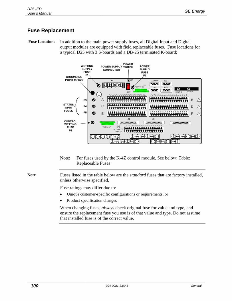
D25 IED User's Manual GE Energy
100 994-0081-3.00-5 General
Fuse Replacement
Fuse Locations In addition to the main power supply fuses, all Digital Input and Digital output modules are equipped with field replaceable fuses. Fuse locations for a typical D25 with 3 S-boards and a DB-25 terminated K-board:
ON
OFF
POWER
A
D25 MAINT IED 1
IED 2UTC
C
E
B
D
F
HDC ANALOG
INPUTS
GND XCOM 1 XCOM 2
SYSFAIL AUX KEY 2 1 2 1 2 1
RADIO
J1 J2 J3
1 3 5 7 9 11 13 15 17 19 21 23 25 27 29 31 33 35 37 392 4 6 8 10 12 14 16 18 20 22 24 26 28 30 32 34 36 38 40
P1 P3 P5 P7 P9P2 P4 P6 P8
1 3 5 7 9 11 13 15 17 19 21 23 25 27 29 31 33 35 37 39
2 4 6 8 10 12 14 16 18 20 22 24 26 28 30 32 34 36 38 40
WETTINGFUSE
F6
INPUTFUSES
POWER SUPPLYCONNECTOR
GROUNDINGPOINT for D25
POWERSWITCHWETTING POWER
SUPPLYFUSE
F2
F3
F4
F5
STATUS
SUPPLYFUSE
F1
!
!
!
1 3 5 7 9 11 13 15 17 19 21 23 25 27 29 31 33 35 37 392 4 6 8 10 12 14 16 18 20 22 24 26 28 30 32 34 36 38 40
CONTROL
Note: For fuses used by the K-4Z control module, See below: Table: Replaceable Fuses
Note Fuses listed in the table below are the standard fuses that are factory installed, unless otherwise specified.
Fuse ratings may differ due to: • Unique customer-specific configurations or requirements, or • Product specification changes
When changing fuses, always check original fuse for value and type, and ensure the replacement fuse you use is of that value and type. Do not assume that installed fuse is of the correct value.

GE Energy D25 IED User's Manual
General 994-0081-3.00-5 101
Fuse Replacement, Continued
Table: Replaceable Fuses
Standard replaceable fuses that are used by the various hardware options.
Fuse Board Type
Rating Where Used Fuse Part #
F1 521-0143 AGC 1.0A 250V 24V Field Supply 940-0021
521-0145 AGC 1.0A 250V 24V Field Supply 940-0021
521-0144 MDL 0.5A 250V 48V Field Supply 940-0215
521-0146 MDL 0.5A 250V 48V Field Supply 940-0215
F2 521-0143 AGC 3A 250V LVPS Power Fuse 940-0007
521-0145 MDL 0.75A 250V HVPS Power Fuse 940-0024
521-0146 MDL 0.75A 250V HVPS Power Fuse 940-0024
521-0144 AGC 3A 250V LVPS Power Fuse 940-0007
F3, F4, & F5
517-0485 AGC 0.25A 250V 12V / 5 mA Wetting 940-0023
517-0486 AGC 0.25A 250V 24V / 5 mA Wetting 940-0023
517-0487 AGC 0.25A 250V 48V Wetting 940-0023
517-0490 AGC 0.5A 250V 24V / 10 mA Wetting 940-0009
517-0488 AGC 0.10A 250V 120V Wetting 940-0155
517-0489 AGC 0.10A 250V 250V Wetting 940-0155
F6 All KE AGC 1.0A 250V Control Voltage Fuse 940-0021
517-0454 AGC 1.0A 250V Control Voltage Fuse 940-0021
517-0455 AGC 1.0A 250V Control Voltage Fuse x 8 ch 940-0021

D25 IED User's Manual GE Energy
102 994-0081-3.00-5 General
Battery Replacement
WESDAC (Main Board) Battery
The WESDAC Board is mounted vertically immediately behind the front panel. It is the first component visible when the front panel is removed.
Locate the Panasonic® BR2/3A (or equivalent) lithium battery near the top-left of the Type III WESDAC board. It is provided to maintain the contents of the NVRAM when the unit is powered down.
Refer to Battery Replacement on page 102 for information on changing this battery.
20 MB Memory Expansion Board Battery
Locate the Tadiran® TL-2100S (or equivalent) lithium battery on the 20 MB Memory Expansion Board. It is provided to maintain the contents of the NVRAM when the unit is powered down.
Refer to Battery Replacement on page 102 for information on changing this battery.
Battery Checking
Check battery voltage using a meter or other measuring device that has a high input impedance (10 MΩ or higher).
Cleaning & Handling of Lithium Batteries
• Use non-conductive cleaning solution to prevent deterioration of battery performance.
• Dry batteries at a temperature below 85° C to prevent seal deformation that may, in turn, result in leakage.
• Avoid: − inversion of polarity − exposure to high temperatures, such as soldering or spot-welding − excessive force to terminals
• Wear gloves or finger caps when handling batteries to keep them clean. • For long-term storage
− keep at temperatures and humidity below normal − avoid shorting or loading while stored.
Battery Replacement
If the battery is disconnected, or if the D25 is never powered down, the life of the battery should exceed five years.
The life of the battery will be severely shortened if the battery is left connected while the D25 is powered down for extended periods or stored.
The battery can be changed with power applied to the D25, so that service is not interrupted.
Note: The status of the battery is provided during the D25 start-up sequence.

GE Energy D25 IED User's Manual
General 994-0081-3.00-5 103
Battery Replacement, Continued
!
Warning
• Removing the battery when the D25 is powered down results in loss of the configuration data and any other database information stored in NVRAM.
• Download the configuration file to restore operation.
!
Warning
• There are many electrostatically sensitive components near the battery. • Extreme caution and proper procedures for servicing electrostatically sensitive
components must be observed.
Recycling of
Batteries
The D25 Lithium battery is recyclable and does not contain mercury, cadmium, or lead in levels above those regulated by the European Union. Recycle the battery according to local waste management regulations.
In accordance with European Directive 2006/66/EC, batteries are marked with the crossed out wheeled bin, which indicates that they cannot be disposed of as unsorted municipal waste in the European Union. Users of batteries must use the collection points available to customers for the return, recycling, and treatment of batteries. Customer participation is important to minimize the negative effects of batteries to the environment and sustain available natural resources. For more information see www.weeerohsinfo.com.
Procedure: Changing Battery
Changing the battery with power applied:
Step Action
Battery Removal
1 Using a plastic or other non-conductive tool, pry the black plastic clip holding the battery away from the battery holder.
2 When free, the battery and clip can be removed together.
3 Remove the clip from the battery, and retain. Battery Replacement
4 Place good battery into battery holder, carefully noting proper polarity.
5 Place clip retained during battery removal across the center of the battery, and press down until it clicks into the retaining notches in the battery holder.
D25 IED User's Manual GE Energy
104 994-0081-3.00-5 General
Battery Replacement, Continued
Lithium Battery Disposal
Totally discharged lithium batteries can be appropriately disposed of as non-hazardous. Refer to Recycling of Batteries above.
Disposal of a fully or partially charged lithium battery as a hazardous waste can be done after it has been first neutralized through an approved secondary treatment.

GE Energy D25 IED User's Manual
General 994-0081-3.00-5 105
Chapter 8: Upgrading and Replacing D25 Modules
Remedial Maintenance
If a board has failed on your D25 or you need to upgrade a specific component, use this section of the guide, which explains: • How to remove and replace the main boards • How to enable and disable Serial XCOM Radio Keying • How to access and change Ethernet XCOM jumpers • How to change the power supply jumpers • How to change Input and Output cards and CT/PT interface modules • How to reconnect power
Module Replacement
About the D25 Modules
• All modules are accessed through the front of the enclosure. • I/O modules can be removed and replaced without disturbing field wiring. • Each printed circuit board (PCB) fits into a guide in the enclosure side panels. • Each daughter board has self-aligning connectors to ensure correct insertion. • All PCBs of different types are keyed to prevent improper insertion into the
wrong location.
Component Location
With the front panel removed and the D25 WESDAC module removed, the modules are located as shown:
D25 PCB/Connector Layout (Front View – WESDAC Card Removed)
Digital Input Boards
XCOM Card
IED/RTC Card
Power Supply Card
Shelf Plate
D/O Board (Upside Down)
A/I Board
PT/CT Modules

D25 IED User's Manual GE Energy
106 994-0081-3.00-5 General
Module Replacement, Continued
Disassembling the D25
You will need to disassemble the unit if it has sustained damage through physical or environmental factors, or if a module or option has to be interchanged to change functionality.
!
Warning
• Always disconnect the power source before servicing and removing components. • Use the puller (located inside of D25 front cover, on the edge of the Indicator
Switch Card) to remove and replace modules.
Always use the puller provided for removing and replacing all modules.
!
Warning
The high voltage area of the D25 High Current KE Digital Output Module is in close proximity to the D25 chassis. Ensure that relay contacts are de-energized before removing the D25 HCKE Digital Output Module.
Background on Connectors
• Connectors for field wiring the Digital Input, DC Analog input cards, and Digital output cards that use compression type connectors are permanently installed into the rear panel of the D25.
• Some Digital output modules have DB-25 connectors that are permanently attached to the module, not the rear panel.
• Connectors on the CT/PT transformers are permanently installed into the rear panel.
• CT/PT primaries are connected to the connectors by quick connect type of connectors.
Procedure: Disassembly
How to remove the front panel and expose the D25 WESDAC module (Main Board):
Step Action Comment
Lower the Front Panel
1 Loosen the four (4) captive screws visible on the front panel
The front panel is hinged on the metal-formed hinges at the lower front edge of the D25.
2 Lower the panel This will expose the inner cavity of the D25
Disconnect Indicator Switch Card
3 Locate the connectors at either end of the ribbon cable.
4 Push open the connector clips, and gently pull to remove the male connector at the WESDAC end of the cable
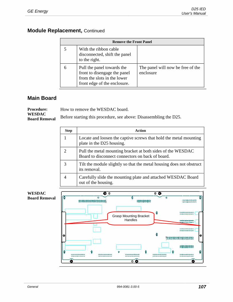
GE Energy D25 IED User's Manual
General 994-0081-3.00-5 107
Module Replacement, Continued
Remove the Front Panel
5 With the ribbon cable disconnected, shift the panel to the right.
6 Pull the panel towards the front to disengage the panel from the slots in the lower front edge of the enclosure.
The panel will now be free of the enclosure
Main Board
Procedure: WESDAC Board Removal
How to remove the WESDAC board.
Before starting this procedure, see above: Disassembling the D25.
Step Action
1 Locate and loosen the captive screws that hold the metal mounting plate in the D25 housing.
2 Pull the metal mounting bracket at both sides of the WESDAC Board to disconnect connectors on back of board.
3 Tilt the module slightly so that the metal housing does not obstruct its removal.
4 Carefully slide the mounting plate and attached WESDAC Board out of the housing.
WESDAC Board Removal
Grasp Mounting Bracket Handles
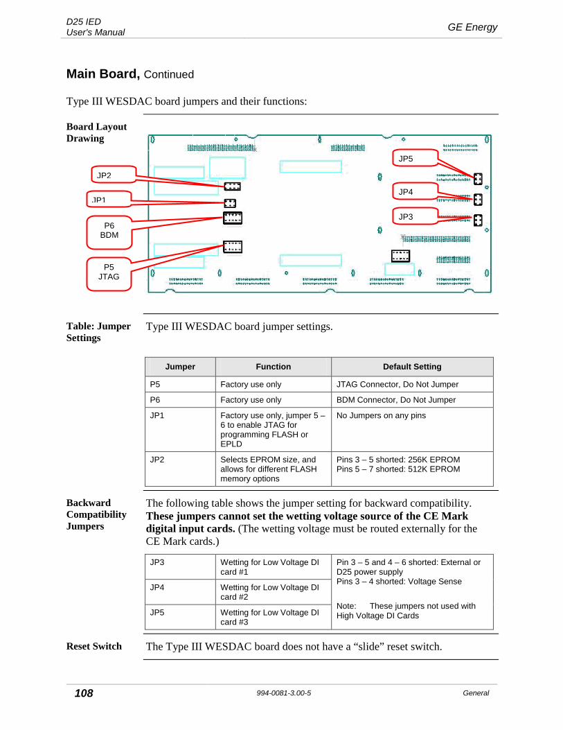
D25 IED User's Manual GE Energy
108 994-0081-3.00-5 General
Main Board, Continued
Type III WESDAC board jumpers and their functions:
Board Layout Drawing
Table: Jumper Settings
Type III WESDAC board jumper settings.
Jumper Function Default Setting
P5 Factory use only JTAG Connector, Do Not Jumper
P6 Factory use only BDM Connector, Do Not Jumper
JP1 Factory use only, jumper 5 – 6 to enable JTAG for programming FLASH or EPLD
No Jumpers on any pins
JP2 Selects EPROM size, and allows for different FLASH memory options
Pins 3 – 5 shorted: 256K EPROM Pins 5 – 7 shorted: 512K EPROM
Backward Compatibility Jumpers
The following table shows the jumper setting for backward compatibility. These jumpers cannot set the wetting voltage source of the CE Mark digital input cards. (The wetting voltage must be routed externally for the CE Mark cards.)
JP3 Wetting for Low Voltage DI card #1
Pin 3 – 5 and 4 – 6 shorted: External or D25 power supply Pins 3 – 4 shorted: Voltage Sense
Note: These jumpers not used with High Voltage DI Cards
JP4 Wetting for Low Voltage DI card #2
JP5 Wetting for Low Voltage DI card #3
Reset Switch The Type III WESDAC board does not have a “slide” reset switch.
JP2
JP1
P6 BDM
P5 JTAG
JP5
JP4
JP3
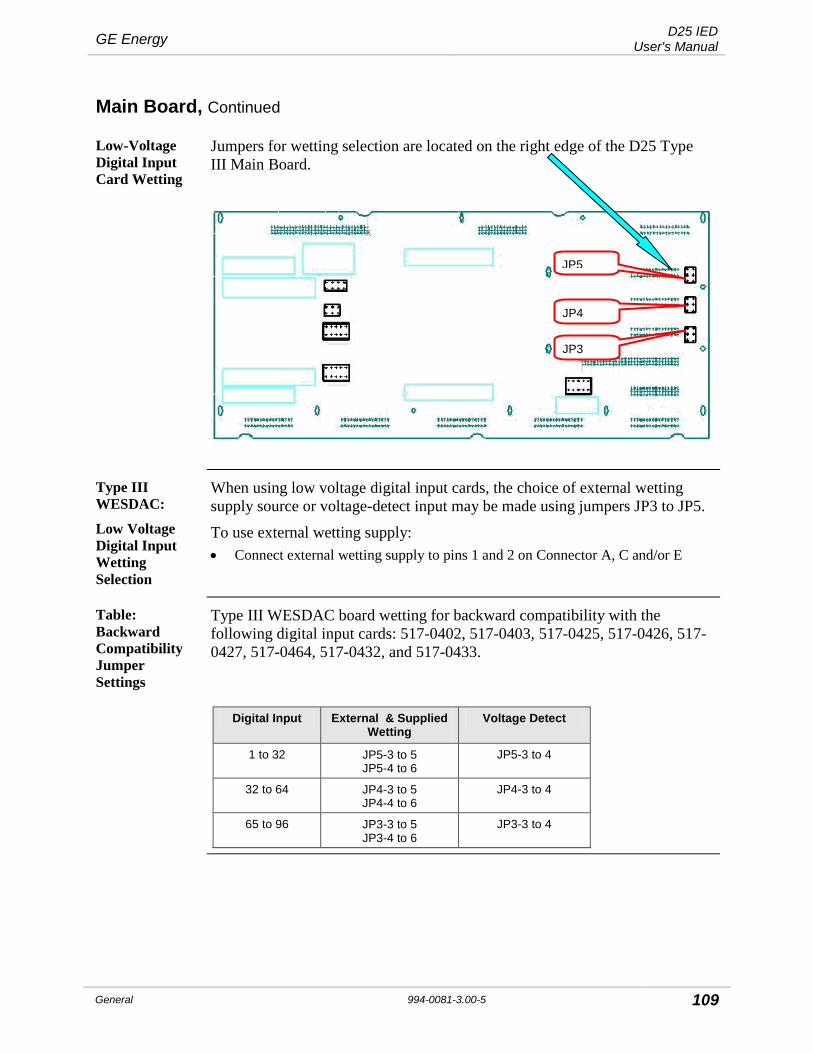
GE Energy D25 IED User's Manual
General 994-0081-3.00-5 109
Main Board, Continued
Low-Voltage Digital Input Card Wetting
Jumpers for wetting selection are located on the right edge of the D25 Type III Main Board.
Type III WESDAC:
Low Voltage Digital Input Wetting Selection
When using low voltage digital input cards, the choice of external wetting supply source or voltage-detect input may be made using jumpers JP3 to JP5.
To use external wetting supply: • Connect external wetting supply to pins 1 and 2 on Connector A, C and/or E
Table: Backward Compatibility Jumper Settings
Type III WESDAC board wetting for backward compatibility with the following digital input cards: 517-0402, 517-0403, 517-0425, 517-0426, 517-0427, 517-0464, 517-0432, and 517-0433.
Digital Input External & Supplied Wetting
Voltage Detect
1 to 32 JP5-3 to 5 JP5-4 to 6
JP5-3 to 4
32 to 64 JP4-3 to 5 JP4-4 to 6
JP4-3 to 4
65 to 96 JP3-3 to 5 JP3-4 to 6
JP3-3 to 4
JP5
JP4
JP3

D25 IED User's Manual GE Energy
110 994-0081-3.00-5 General
Main Board, Continued
Type III WESDAC Wetting Jumper Detail (Backward Compatibility)
Jumpers shown are for the first (top) 32-point module. Jumpers (J4 and J3) for the other two modules work in the same way.
1 3 5
2 4 6
1 3 5
2 4 6
No Wetting (Voltage Detect) External or
Supplied Wetting
.
JP5 JP5
Note: Supplied wetting voltage is 24 or 48 Volts: depends on power supply used.
Note Supplied Wetting option is not available if the Graphics Display panel is installed.
Procedure: Board Replacement
How to replace the WESDAC Board:
Step Action
1 Hold the mounting brackets at each side of the module.
2 Tilt the card slightly, and insert the top first, ensuring that the battery connections do not come into contact with the metal housing.
3 Carefully position the board so that: − the alignment pins align with the holes at the top and bottom of
the WESDAC Board − the captive screws align with their holes − the female connectors on the rear of the WESDAC Board align
with the male connectors of other boards
4 Press the WESDAC Board firmly into position.
5 Tighten all the mounting screws to ensure the WESDAC Board connectors are firmly attached and the board is grounded.

GE Energy D25 IED User's Manual
General 994-0081-3.00-5 111
DDSP Modules
DDSP Modules Dual DSP (DDSP) modules contain the analog-to-digital conversion and digital signal processing (DSP) circuitry required for processing analog signals from the AC analog input cards.
The following DDSP variants are available: • DDSP 32 MHz, 1 MB Memory (504-0009) – Special Order • DDSP 50 MHz, 1 MB Memory (504-0011) – Obsolete • DDSP 50 MHz, 2 MB Memory (504-0015)
Location DDSP board is mounted on top the WESDAC Board, just left of center.
Removing the DSP Board
Carefully grasp the board on both sides, and pull away from the WESDAC Board. A slight rocking motion may assist in freeing the board from its connectors
Diagram of Type I DSP Module
Note: The DDSP card is mounted with component side facing toward the
WESDAC main board.
Replacing the DSP Board
1. Carefully position the DDSP Board on top of the WESDAC Board, and align the connectors.
2. Firmly press down on the connectors until completely seated with WESDAC board connectors.
!
Warning
Polarized Connectors. The DDSP Cards can only be inserted right side up.
DO NOT ATTEMPT TO INSTALL UPSIDE DOWN.
To Remove, Grasp here and pull up
To Remove, Grasp at both sides and pull up
To Replace, press firmly on connectors
To Replace, press firmly on connectors

D25 IED User's Manual GE Energy
112 994-0081-3.00-5 General
Memory Expansion Board
Memory Expansion Board
Memory Expansion board is a general purpose RAM card that can provide extra memory for: • larger, more complex configurations • file storage for use by the oscillography waveform recording and power quality
functions of the D25.
The module is a removable daughter card of the D25 WESDAC module.
Location Memory Expansion module is mounted on top of the WESDAC (Main) Board.
Removing the Memory Expansion Board
Carefully grasp the board on both sides, and pull away from the WESDAC Board.
A slight rocking motion may assist in freeing the board from its connectors
Replacing the Memory Expansion Board
1. Carefully position the Memory Expansion board atop the WESDAC Board, and align the connectors.
2. Firmly press down on the connectors until completely seated with WESDAC board connectors.
!
Caution
Do not press down on the center of the Memory Expansion board while installing it; this will result in damage to the board. Instead, press down on the area directly on top of the connectors at the top and bottom of the Memory Expansion board
Shelf Plate
Shelf Plate The Shelf Plate is the metal plate that carries the Power Supply, IED/RTC card and the optional XCOM card.
Servicing or replacing any of these components requires the removal of the Shelf Plate.
Locking Brackets
Two Locking Brackets secure the Shelf Plate, one on each side of the enclosure.
These brackets are designed to prevent the accidental removal of the Shelf Plate when the WESDAC Board is pulled out of the enclosure
!
External Connections
Remove all external connections from the IED/RTC card and/or the XCOM card before removing the Shelf plate.

GE Energy D25 IED User's Manual
General 994-0081-3.00-5 113
Shelf Plate, Continued
Shelf Plate Location
Each of the three cards on the Shelf Plate is connected to the WESDAC Board through a DIN connector.
Locking Brackets Shelf Plate Field terminations for the Power Supply are made through a five-pin connector positioned on the back panel of the D25.
Procedure: Removing the Shelf Plate
How to remove the shelf plate.
After removing all connections from the IED/RTC and XCOM cards:
Step Action
1 Locate the two levers that secure the metal Shelf Plate in the D25 housing.
Two labels, one on each side panel inside the enclosure, identify the Locking Bracket locations.
2 Lift the front end of the locking bracket levers until they click into the up position.
3 Carefully slide the Shelf Plate and attached cards out of the housing.
Locking Brackets
Shelf Plate
LIFT LATCH TO
RELEASE

D25 IED User's Manual GE Energy
114 994-0081-3.00-5 General
Shelf Plate, Continued
Procedure: Replacing the Shelf Plate
How to replace the Shelf Plate:
Step Action
1 Before inserting the Shelf Plate into the enclosure, lift the front end of the locking bracket levers until they click into the up position.
2 Align the Shelf Plate with the top card guides, and carefully slide the Shelf Plate and attached cards into the housing.
3 Firmly push the Plate into the housing until it is fully engaged into its grounding clips at the rear of the enclosure. Note: The Locking Brackets should fall back into a “locked”
position. Check this by pulling on the Plate to see if it is secure.
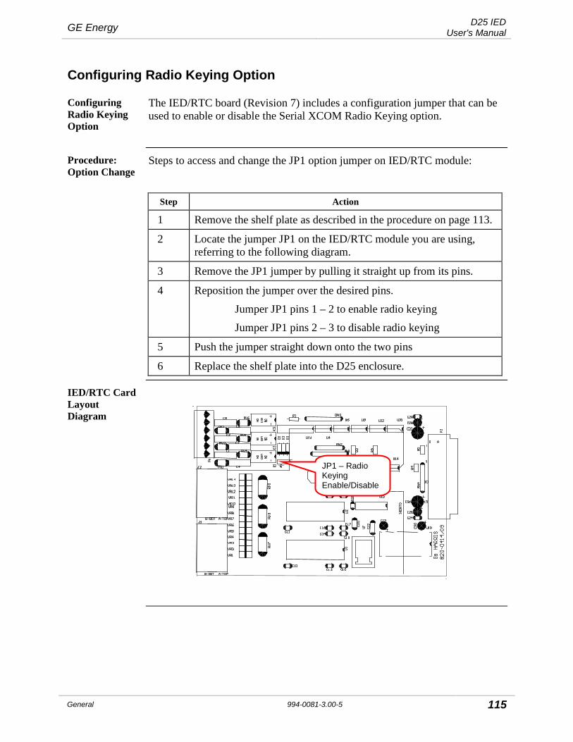
GE Energy D25 IED User's Manual
General 994-0081-3.00-5 115
Configuring Radio Keying Option
Configuring Radio Keying Option
The IED/RTC board (Revision 7) includes a configuration jumper that can be used to enable or disable the Serial XCOM Radio Keying option.
Procedure: Option Change
Steps to access and change the JP1 option jumper on IED/RTC module:
Step Action
1 Remove the shelf plate as described in the procedure on page 113.
2 Locate the jumper JP1 on the IED/RTC module you are using, referring to the following diagram.
3 Remove the JP1 jumper by pulling it straight up from its pins.
4 Reposition the jumper over the desired pins.
Jumper JP1 pins 1 – 2 to enable radio keying
Jumper JP1 pins 2 – 3 to disable radio keying
5 Push the jumper straight down onto the two pins
6 Replace the shelf plate into the D25 enclosure.
IED/RTC Card Layout Diagram
JP1 – Radio Keying Enable/Disable

D25 IED User's Manual GE Energy
116 994-0081-3.00-5 General
D25 Ethernet Card 100Base (10/100Base-T and 100Base-FX)
The D25 100Base card (GE part number 504-0305LF) is a dual-channel 10/100BaseT and 100Base-FX network card that plugs into the XCOM slot on the D25. It provides local area network connections for two RJ-45 connectors and two ST connectors on the rear panel. The RJ-45 data rate is automatically detected and set to either 10 Mbps or 100 Mbps.
Configuration Options
There are no selectable options on the 10/100Base-T and 100Base-FX Ethernet card.
Fiber Optic Cabling
You can use the following glass optical fiber (GOF) cabling with the D25 100Base FX:
• 50/125 μm core/cladding multi-mode (gradient index) cable • 62.5/125 μm core cladding multi-mode (gradient index) cable • 100/140 μm core/cladding multi-mode (gradient index) cable • 200 μm core Hard-Clad Silica (HCS) multi-mode (step index) cable
You can use the following fiber optic terminations for D25 cabling: • ST Connectors
When calculating cable length, consider the following optical power levels: • 100BaseFX optical transmitter power is –15.0 ± 4 dBm • 100BaseFX optical fiber receiver sensitivity is typically –33.9 dBm
LED transmitters are classified as IEC 60825-1 Accessible Emission Limit (AEL) Class 1M. Class 1M devices are considered eye safe to the unaided eye. Do not view directly with optical instruments.
SQE test and Jabber Support
Note
100BASE Ethernet does not have a provision to enable SQE test nor Jabber as this is not part of the 100 Mbps standard. Refer to IEEE 802.3 clause 24.3.2.2 for further details on the removal of SQE test and Jabber in 100 Mbps Ethernet.

GE Energy D25 IED User's Manual
General 994-0081-3.00-5 117
D25 Ethernet Card 100Base (10/100Base-T and 100Base-FX), Continued
Ethernet Card Diagram

D25 IED User's Manual GE Energy
118 994-0081-3.00-5 General
Power Supply Card
Table: Changing Power Supply Field Voltage Output
Optional power supplies equipped with a selection jumper to switch the field voltage output to or from 24 V or 48 Vdc.
Part # Default Field O/P Description
521-0143 24 Vdc LVPS: 60 – 150 Vdc / 85 - 135 Vac
521-0144 48 Vdc LVPS: 60 – 150 Vdc / 85 - 135 Vac
521-0145 24 Vdc HVPS: 150 - 350 Vdc / 187 - 265 Vac
521-0146 48 Vdc HVPS: 150 - 350 Vdc / 187 - 265 Vac
Power Supply Component Locations
P3 – Field Supply Voltage Selector F1 – Field
Supply Fuse
F2 – Power Input Fuse
SW1 – Power Switch
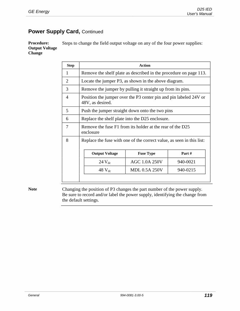
GE Energy D25 IED User's Manual
General 994-0081-3.00-5 119
Power Supply Card, Continued
Procedure: Output Voltage Change
Steps to change the field output voltage on any of the four power supplies:
Step Action
1 Remove the shelf plate as described in the procedure on page 113.
2 Locate the jumper P3, as shown in the above diagram.
3 Remove the jumper by pulling it straight up from its pins.
4 Position the jumper over the P3 center pin and pin labeled 24V or 48V, as desired.
5 Push the jumper straight down onto the two pins
6 Replace the shelf plate into the D25 enclosure.
7 Remove the fuse F1 from its holder at the rear of the D25 enclosure
8 Replace the fuse with one of the correct value, as seen in this list:
Output Voltage Fuse Type Part #
24 Vdc AGC 1.0A 250V 940-0021
48 Vdc MDL 0.5A 250V 940-0215
Note Changing the position of P3 changes the part number of the power supply. Be sure to record and/or label the power supply, identifying the change from the default settings.

D25 IED User's Manual GE Energy
120 994-0081-3.00-5 General
Digital Input Cards
Digital Input S-Cards
A D25 may be equipped with up to three S-Cards.
Cards may not be the same part numbers: the wetting voltage may be different, so use care when replacing cards.
Field terminations for the digital inputs and external wetting power supply are made through two 40-pin card edge connectors positioned on the back panel of the D25.
!
Use Pullers
Always use the PCB pullers shipped with the D25 to remove and replace S Cards.
S Card Locations
Each S Card is connected to the WESDAC Board through a 2x16 pin DIN connector:
DI Card #1
DI Card #2
DI Card #3
Removing the S Card
1. Use two PCB pullers to slide the S Card toward the front of the D25.
2. Use firm but gentle pressure to disconnect the card.
Replacing the S Card
1. Position the S Card on the slide guide, and carefully push the card into the D25 housing. Use the following table to determine the correct slot to insert the card.
2. Use firm but gentle pressure to push the card into place.
Table: Positioning S Cards
Use this table to determine the correct slot to insert the card.
Card Inputs Location
1 1 - 32 Second slot from the top of the D25
2 33 – 64 Third slot from the top of the D25
3 65 – 96 Fourth slot from the top of the D25
DI Card #3
DI Card #2
DI Card #1

GE Energy D25 IED User's Manual
General 994-0081-3.00-5 121
Digital Output Card
KE Card Mount the KE Card component-side down in the fifth slot (from the top of the D25):
!
Use Pullers
Always use the pullers shipped with the D25 to remove and replace KE Card.
!
Warning
The high voltage area of the D25 High Current KE Digital Output Module is in close proximity to the D25 chassis. Ensure that relay contacts are de-energized before removing the D25 HCKE Digital Output Module.
Removing the KE Card
Using one PCB puller, slide the KE Card toward the front of the D25.
Use firm but gentle pressure when pulling the card out.
Replacing the KE Card
Position the KE Card component side down in the fifth slot from the top of the D25, and carefully push the card into the D25 housing.
Use firm but gentle pressure to push the card into place.
!
KE Card
The KE Card must be installed component side down.
Attempts to install the KE Card in any other orientation will cause damage to the components.
DO Board (Upside Down)
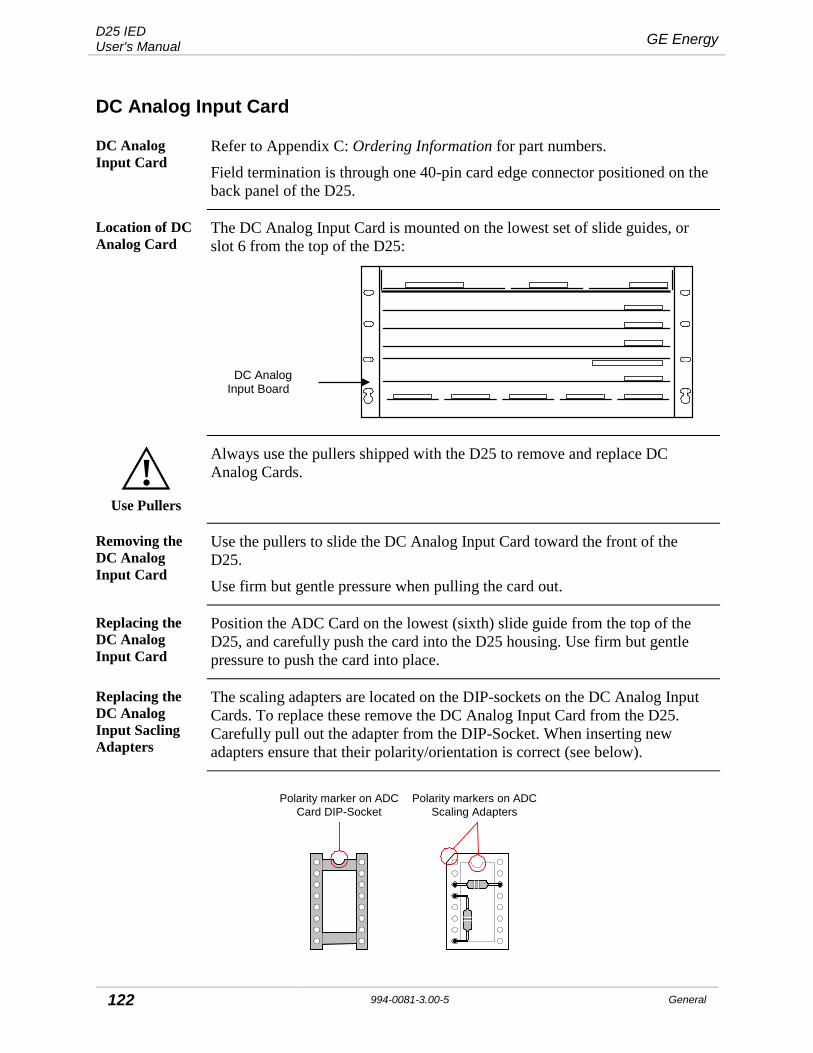
D25 IED User's Manual GE Energy
122 994-0081-3.00-5 General
DC Analog Input Card
DC Analog Input Card
Refer to Appendix C: Ordering Information for part numbers.
Field termination is through one 40-pin card edge connector positioned on the back panel of the D25.
Location of DC Analog Card
The DC Analog Input Card is mounted on the lowest set of slide guides, or slot 6 from the top of the D25:
DC Analog Input Board
!
Use Pullers
Always use the pullers shipped with the D25 to remove and replace DC Analog Cards.
Removing the DC Analog Input Card
Use the pullers to slide the DC Analog Input Card toward the front of the D25.
Use firm but gentle pressure when pulling the card out.
Replacing the DC Analog Input Card
Position the ADC Card on the lowest (sixth) slide guide from the top of the D25, and carefully push the card into the D25 housing. Use firm but gentle pressure to push the card into place.
Replacing the DC Analog Input Sacling Adapters
The scaling adapters are located on the DIP-sockets on the DC Analog Input Cards. To replace these remove the DC Analog Input Card from the D25. Carefully pull out the adapter from the DIP-Socket. When inserting new adapters ensure that their polarity/orientation is correct (see below).
Polarity marker on ADCCard DIP-Socket
Polarity markers on ADCScaling Adapters

GE Energy D25 IED User's Manual
General 994-0081-3.00-5 123
CT/PT Modules
CT/PT Interface Modules
The CT and PT interface modules are field replaceable.
Each of the maximum five modules holds three CTs or PTs, for a total of fifteen transformers.
!
Use Pullers
CT input wiring must be shorted externally before servicing the CT transformers • Open circuiting a Feeder CT will result in feeder voltage being present at the
secondary of the CT. • These Hazardous Voltages may result in equipment damage, shock, burns or
death
Procedure: Removal
Steps to remove the CT and/or PT interface modules
Step Action
1 Unplug the transformer connectors to disconnect the secondaries from the module.
2 Remove the module by sliding it toward the front of the open D25, then lifting it from the Snap-On PEM studs.
3 Move it forward and out the front of the open D25.
Procedure: Replacement
Steps to replace the CT and/or PT interface modules.
Note: The use of 42x nominal CT modules requires that you enter calibration factors in the D25’s configuration. See: 42x Nominal CT Module
Step Action
1 Move the card into position and lower it onto the Snap-On PEM studs.
2 Push it into the D25 until the card snaps firmly in place on the PEM studs.
3 Plug the transformer secondaries into connectors, observing proper orientation and arrangement. Transformer secondary wires should not cross each other.

D25 IED User's Manual GE Energy
124 994-0081-3.00-5 General
CT/PT Modules, Continued
!
Removing or Replacing the
CT/PT Transformers
CT input wiring must be shorted externally before servicing the CT transformers • Open circuiting a Feeder CT will result in feeder voltage being present at the
secondary of the CT. • These Hazardous Voltages may result in equipment damage, shock, burns or
death
Note Before accessing the transformers, you must remove the modules mounted directly above.
Refer to the procedures on the previous page for removal/replacement of those modules.
Background Due to the stiffness of the wires on the primary of the standard 5 A CTs, the transformers are manufactured with wires of two different lengths, to facilitate easier assembly into the bottom of the D25 enclosure.
The part numbers are as follows: • Standard short lead 5 A CT:
• Standard long lead 5 A CT:
450-0087
450-0088
The optional 42 X 5 A CTs are manufactured with both long and short primary wires. The unused wire should be removed from the transformer when installed. • 42 X Overcurrent long/short lead 5 A CT: 450-0108
If replacement 5 A CTs are required, be sure to order the transformer with the correct lead length.
Note Standard and 42 X overcurrent 1 A CTs, and all PTs, have leads flexible enough that two types are not required.

GE Energy D25 IED User's Manual
General 994-0081-3.00-5 125
CT/PT Modules, Continued
Long/Short Lead Transformer Mounting Diagram
Short lead transformers are mounted in the row nearest the rear of the enclosure, Long lead transformers are mounted in the row closest to the front:
Note: The transformer’s leads are omitted from the diagram for clarity.
Procedure: Removal
How to remove the CT or PT transformers from the D25 enclosure:
Step Action
1 Disconnect the quick fasteners on the primary and secondary windings of the transformers.
2 Remove the single nut from the PEM stud
3 Lift the transformer off the stud, and slide it sideways until free of the slot in the bottom plate of the enclosure.
4 Lift the transformer out.
Procedure: Replacement
How to replace CT or PT transformers into the D25 enclosure:
Step Action
1 Slide the end of the transformer into the appropriate slot in the bottom plate of the enclosure
2 Lower the other end of the transformer onto the PEM stud.
3 Tighten the nut onto the PEM stud.
4 Replace the quick fasteners onto the primary and secondary connection points.
Short-Lead CT
Long-Lead CT
Rear of Enclosure
D25 IED User's Manual GE Energy
126 994-0081-3.00-5 General
CT/PT Modules, Continued
42x Nominal CT Module
To compensate for the current transformer’s possible magnitude inaccuracy, it must be calibrated using a precision current source.
Use the following procedures to measure the magnitude error at both metering and over-current levels. Use your measurements to calculate the calibration factors to compensate for the gain error.
Note: The label inside the D25 box stating the compensation factors should be removed or corrected by the technician. A new label will not be supplied with the CT/PT modules.
Procedure: Metering Range Calibration (0% - 195%)
Steps to calibrate the transformer for inputs in the metering range:
Step Action
1. Using ConfigPro: • Set the calibration and correction factors for the phase and magnitude
to the following default values: 1.00000 for magnitude, and 0.00000 for phase. − To set the calibration factors, go to
D25 AC Configuration>Calibration tab>Internal Calibration tab − To set the correction factors, go to
D25 AC Configuration >Calibration tab>External Correction tab. • Set the configured frequency to match the test signal’s frequency
(either 50 or 60 Hz). − To set the configured frequency, go to:
D25 DCA Configuration>Advanced tab>Line Frequency • Set each input’s magnitude point Report Deadband to zero and
Averaging ON. − To set the Report Deadband, go to:
D25 AC Configuration>I/O Configuration tab>Physical AC Analog Inputs>Report Deadband
− To set the Averaging, go to: D25 AC Configuration>I/O Configuration tab>Physical AC Analog Inputs>Averaging
2. Generate and download the configuration to the unit you are calibrating.
3. For each input use a precision AC current source to inject the test currents indicated in the table in Step 4

GE Energy D25 IED User's Manual
General 994-0081-3.00-5 127
CT/PT Modules, Continued
Procedure: Metering Range Calibration (0% - 195%) (continued)
Step Action
4. Using the D25 AC Input Engineering Value Displays (available through the B050-0 WESMAINT application), record the raw magnitude values for each input you are calibrating.
Verify that the reported values are within the following tolerances:
CT Type: 1A Part Number: 450-0107
For Test Current… Expected Raw Value is… Tolerance
1.000 Arms +/- 0.05% 2048 +/- 20 counts
CT Type: 5A Part Number: 450-0108
For Test Current… Expected Raw Value is… Tolerance
5.000 Arms +/- 0.05% 2048 +/- 20 counts
5. Calculate the 0-195% magnitude calibration factor for each input using the data gathered in Step 4.
Use the following formula:
Magnitude Calibration Factor = expected value / measured value For example, if the measured value is 2045, the magnitude calibration factor is:
2048/2045 = 1.00147
6. Enter the calibration factors in the Magnitude (0% - 195%) column for each input into the configuration (under D25 AC Configuration > Calibration tab > Internal Calibration tab).
7. Generate and download the configuration to the unit.
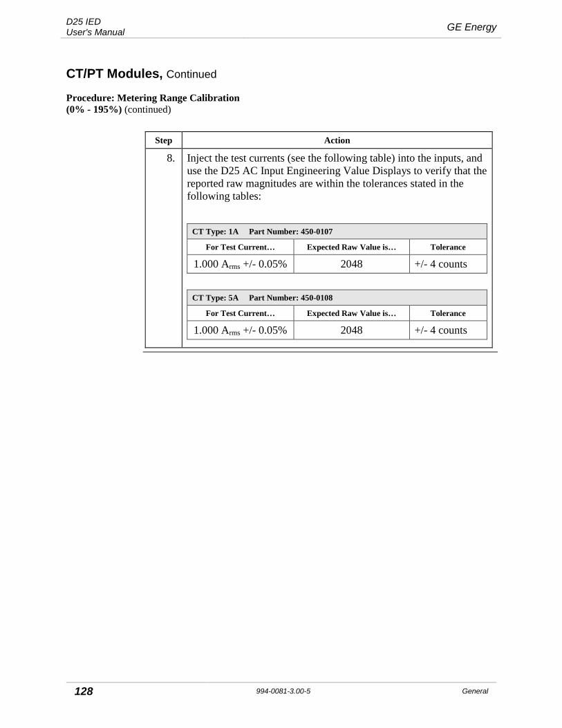
D25 IED User's Manual GE Energy
128 994-0081-3.00-5 General
CT/PT Modules, Continued
Procedure: Metering Range Calibration (0% - 195%) (continued)
Step Action
8. Inject the test currents (see the following table) into the inputs, and use the D25 AC Input Engineering Value Displays to verify that the reported raw magnitudes are within the tolerances stated in the following tables:
CT Type: 1A Part Number: 450-0107
For Test Current… Expected Raw Value is… Tolerance
1.000 Arms +/- 0.05% 2048 +/- 4 counts
CT Type: 5A Part Number: 450-0108
For Test Current… Expected Raw Value is… Tolerance
1.000 Arms +/- 0.05% 2048 +/- 4 counts

GE Energy D25 IED User's Manual
General 994-0081-3.00-5 129
CT/PT Modules, Continued
Procedure: Over-current Range Calibration (195% - F.S.)
Steps to calibrate the transformer for inputs in the over-current range.
Step Action
1. Using ConfigPro: • Set the calibration and correction factors for the phase and magnitude
to the following default values: 1.00000 for magnitude, and 0.00000 for phase. − To set the calibration factors, go to
D25 AC Configuration>Calibration tab>Internal Calibration tab − To set the correction factors, go to
D25 AC Configuration >Calibration tab>External Correction tab. • Set the configured frequency to match the test signal’s frequency
(either 50 or 60 Hz). − To set the configured frequency, go to:
D25 DCA Configuration>Advanced tab>Line Frequency • Set each input’s magnitude point Report Deadband to zero and
Averaging ON. − To set the Report Deadband, go to:
D25 AC Configuration>I/O Configuration tab>Physical AC Analog Inputs>Report Deadband
− To set the Averaging, go to: D25 AC Configuration>I/O Configuration tab>Physical AC Analog Inputs>Averaging
2. Generate and download the configuration to the unit you are calibrating.
3. For each input use a precision AC current source to inject the test currents indicated in the table in Step 4

D25 IED User's Manual GE Energy
130 994-0081-3.00-5 General
CT/PT Modules, Continued
Procedure: Over-current Range Calibration (195% - F.S.) (continued)
Step Action
4. Using the D25 AC Input Engineering Value Displays (available through the B050-0 WESMAINT application), record the raw magnitude values for each input you are calibrating.
Verify that the reported values are within the following tolerances:
CT Type: 1A Part Number: 450-0107
For Test Current… Expected Raw Value is… Tolerance
4.000 Arms +/- 0.05% 8192 +/- 200 counts
CT Type: 5A Part Number: 450-0108
For Test Current… Expected Raw Value is… Tolerance
20.000 Arms +/- 0.05%
8192 +/- 200 counts
5. Calculate the 195-FS magnitude calibration factor for each input using the data gathered in Step 4.
Use the following formula:
Magnitude Calibration Factor = expected value / measured value For example, if the measured value is 8195, the magnitude calibration factor is:
8192/8195 = 0.99963
6. Enter the calibration factors in the Magnitude (195% - FS) for each input into the configuration (under D25 AC Configuration > Calibration tab > Internal Calibration tab).
7. Generate and download the configuration to the unit.

GE Energy D25 IED User's Manual
General 994-0081-3.00-5 131
CT/PT Modules, Continued
Procedure: Over-current Range Calibration (195% - F.S.) (continued)
8. Inject the test currents (see the following table) into the inputs, and use the D25 AC Input Engineering Value Displays to verify that the reported raw magnitudes are within the tolerances stated in the following table:
CT Type: 1A Part Number: 450-0107
For Test Current… Expected Raw Value is… Tolerance
4.000 Arms +/- 0.05% 8192 +/- 41 counts
CT Type: 5A Part Number: 450-0108
For Test Current… Expected Raw Value is… Tolerance
20.000 Arms +/- 0.05%
8192 +/- 41 counts
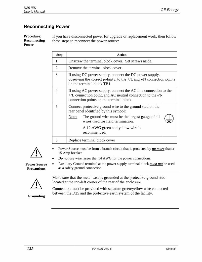
D25 IED User's Manual GE Energy
132 994-0081-3.00-5 General
Reconnecting Power
Procedure: Reconnecting Power
If you have disconnected power for upgrade or replacement work, then follow these steps to reconnect the power source:
Step Action
1 Unscrew the terminal block cover. Set screws aside.
2 Remove the terminal block cover.
3 If using DC power supply, connect the DC power supply, observing the correct polarity, to the +/L and -/N connection points on the terminal block TB1.
4 If using AC power supply, connect the AC line connection to the +/L connection point, and AC neutral connection to the -/N connection points on the terminal block.
5 Connect protective ground wire to the ground stud on the rear panel identified by this symbol: Note: The ground wire must be the largest gauge of all
wires used for field termination. A 12 AWG green and yellow wire is
recommended.
6 Replace terminal block cover
!
Power Source Precautions
• Power Source must be from a branch circuit that is protected by no more than a 15 Amp breaker
• Do not use wire larger that 14 AWG for the power connections. • Auxiliary Ground terminal at the power supply terminal block must not be used
as a safety ground connection.
!
Grounding
Make sure that the metal case is grounded at the protective ground stud located at the top-left corner of the rear of the enclosure.
Connection must be provided with separate green/yellow wire connected between the D25 and the protective earth system of the facility.

GE Energy D25 IED User's Manual
General 994-0081-3.00-5 133
Chapter 9: Troubleshooting
This section provides guidance in troubleshooting system malfunctions and WESMAINT error messages: • Runtime and start-up problems • Initialization errors • LAN-based errors
Note that Plant I/O errors are reported as changes in the state of specific digital input points. These events will be logged in the SOE Buffer Display in WESMAINT
In severe cases, the WESMAINT application may not run at all. If this happens, then access the system monitor, type EL /P and press ENTER to display a low-level error log.
If you fail to solve a problem, then contact GE Energy for assistance.
Run-time and Startup Problems
Table: Diagnosing Problems
Use the following table to diagnose problems with the D25:
Symptom Possible Causes Suggestions
Active Operations Aborted
Controls Switch is in the Local position. D25 Plant I/O Subsystem monitoring detects that the supply voltage is not available.
Move the Controls Switch to the Local position. Verify supply voltage source.
Active Requests Aborted
The D25 Plant I/O Subsystem monitoring detects a conflict between desired and actual coil status (a coil is not energized when it should be).
Verify coil status.
Digital Output Requests Rejected
Controls Switch is in the Local position. D25 Plant I/O Subsystem monitoring detects that the supply voltage is not available. The D25 Plant I/O Subsystem monitoring detects a conflict between desired and actual coil status (a coil is not energized when it should be).
Move the Controls Switch to the Local position. Verify supply voltage source. Verify coil status.

D25 IED User's Manual GE Energy
134 994-0081-3.00-5 General
Run-time and Startup Problems, Continued
Symptom Possible Causes Suggestions
Queued Requests Cleared
Controls Switch is in the Local position. D25 Plant I/O Subsystem monitoring detects that the supply voltage is not available. The D25 Plant I/O Subsystem monitoring detects a conflict between desired and actual coil status (a coil is not energized when it should be).
Move the Controls Switch to the Local position. Verify supply voltage source. Verify coil status.
System Hangs Watchdog failure
Plant I/O Watchdog Failure
Plant I/O Subsystem integrity is faulty.
Remove and restore power to the D25.
Digital Output Points are Disabled
The Local/Remote switch is in the Local position.
Move the Local/Remote switch to the Remote position.
Digital Input Points Do Not Register
Incorrect wiring, Protection fuse is blown
Verify wiring, verify fuse is in place and is in good condition
Communication Watch Dog Failure
Internal system monitors detect serious errors.
D25 Does Not Operate Remotely
The Local/Remote switch is in the Remote position, but the D25 does not contain a Digital output Card, or the Digital output Card malfunctions.
Verify that a Digital output Card is installed. Verify that the Digital output Card functions correctly.
Coil Status Check The D25 Plant I/O Subsystem monitoring detects a conflict between desired and actual coil status.
Verify coil status.
Control Voltage Not Available
Output has failed.
Hardware Watchdog Digital output coils are not in the state requested by the software
Plant I/O Subsystem failure
Digital Output Failure Control voltage not available, coil status check, hardware watchdog error condition, or protection fuse is blown
RAM Check Failure System start-up fails Use WESMAINT II+ to view the error message.
NVRAM Check Failure System start-up fails Use WESMAINT II+ to view the error message.
Application Checksum Failure
System start-up fails Use WESMAINT II+ to view the error message.
BootROM Checksum Failure
System start-up fails Use WESMAINT II+ to view the error message.

GE Energy D25 IED User's Manual
General 994-0081-3.00-5 135
Start-Up Failure RAM check, NVRAM check, Application checksum, or BootROM checksum failed during system start-up
Use WESMAINT II+ to view the error message.
System Shut Down RAM, NVRAM, FLASH, or BootROM internal system diagnostics failed
Use WESMAINT II+ to view the error message.
Only the System Monitor is Running
No valid application code is detected.
Load application code.
Code Download Failure
Download interrupted or data error encountered in downloaded file. Baud rate set too high.
Clear Flash EPROM memory. Restart download procedure. Reduce baud rate to 19200 or less.
Cannot Download Code
Logged into the Application Monitor Exit Application Monitor, and launch System Monitor
Note: When using a D25 with a High Current Control Card (P/N 517-0492) installed, also consult the ‘Using the Current-Monitoring Digital Outputs’ for further details on rules regarding current monitoring and current seal-in.
Initialization Errors
Overview The normal case is that the configuration and code in the Boot file match those in the memory of the client, thus causing the client to initialize immediately.
However, several error situations related to initialization can occur with file transfers.
Symptom Possible Causes Suggestions
BootROM Error Corrupted or incorrect configuration loaded in NVRAM
Press ‘y’ during bootup to enter D25 system monitor, then download configuration.
TFTP ERROR Configuration was not completed or data corruption has occurred at the server
Use WESMAINT II+ to view the error message.
Applications Not Enabled
Configuration was not completed or data corruption has occurred at the server
Use WESMAINT II+ to view the error message.
System Restarts Data download failure Use WESMAINT II+ to view the error message.
Only diagnostic input can be entered
No configuration is detected in either NVRAM or in EPROM on start-up
Download a configuration remotely via the system monitor, and reboot
System error No configuration is detected in either NVRAM or in EPROM on start-up
Download a configuration remotely via the system monitor, and reboot

D25 IED User's Manual GE Energy
136 994-0081-3.00-5 General
LAN-Based Problems
Overview Several failure cases are possible in the BootP initialization sequence.
Under fault conditions such as loss of one or more devices, the system will continue to operate at whatever level of service is possible — even without LAN address, code, and configuration servers.
Notes • BootP request time-out is factory set to 2 seconds. • The default time-out is 5 seconds.
Symptom Possible Causes Suggestions
No response to repeated BootP request
BootP client times out without a valid response. Invalid code and/or configuration
Increase communication timeout. Verify BootP configuration
Null file name for the Boot file appears in the BootP response
BootP server either does not have a Boot File for the device or does not support TFTP read requests
Use WESMAINT II+ to view the error message.
Invalid information in the BootP response
BootP server does not have correct information available for the client. Either the system has not been completely configured, or the BootP server has suffered data loss or corruption.
Use WESMAINT II+ to view the error message.
Late response to BootP requests
Invalid information for the Boot File Use WESMAINT II+ to view the error message.
Time Out System waiting for a data block within a file transfer
Verify communication setup
Checksum Error File download time-out Verify communication setup, file integrity
Run Time Behavior File name received in a write request is not the Boot File
Verify BootP configuration
Database Tables Created or Modified
File name received in a write request is not the Boot File
Verify BootP configuration
Diagnostics display locally only
Internal hardware verification failure
Remote Display Failure
LAN stack and diagnostic interface failure
Time-out LAN address acquisition failed. Boot File Acquisition failure
Verify that code and configuration are the correct versions.
User Processing Halts Restart sequence fails to verify address, boot file, code, and configuration
Load updated files for the restart sequence.
Restart Sequence Failure
Address, boot file, code, and/or configuration verification failure
Load updated files for the restart sequence.
Boot File Acquisition Failure
System times out Verify communication setup
Code / Configuration File Acquisition Failure
iSCS device requires code or configuration
Load updated files for the restart sequence.
GE Energy D25 IED User's Manual
General 994-0081-3.00-5 137
Reporting Problems
If the D25 crashes, call GE Energy for assistance. There is specific information that will help us to diagnose what is causing your system to crash.
D25 Installation Gather the following information about the particular D25 installation that has crashed: 1. Are there any IEDs, relays, meters, etc. connected to the D25? If so, what are
they, what protocol do they speak, and who manufactures them? 2. Are there any master stations or master remotes collecting data from the D25? If
so, what are they, what protocol do they speak, and who manufactures them? 3. What communications equipment is connected between the RTU and other
devices? (E.G. modems, media converters, line adapters, data concentrators, breakout boxes, protocol analyzers, etc.)
4. What are the media for the communications? (E.G., leased line, unlicensed radio, etc.)
5. What is the D25’s part number? What are the part numbers of the installed D25 options? What is the serial number of the D25 and its chassis?
Note: In the case of a repeat crash where the D25 installation has not changed, you do not have to send the installation information to us again.
D25 History We would like the history of the D25 that has crashed. Questions that you should be prepared to answer are: 1. Is the D25 in service? If so, how long has the D25 been installed in the field? 2. Has the D25 configuration changed recently? 3. Has the D25 software been recently upgraded? 4. Was there any unique weather pattern in the area of the D25 prior to the crash? 5. Were there any unique disturbances prior to the crash? (E.G. faults on line,
breakers closing, communication problems, etc.) 6. Were there any field personnel on site during the crash? 7. Was any maintenance being conducted on the D25, the equipment in the vicinity
of the D25, or equipment connected to the D25 prior to the crash?
68K Monitor Error Log
The 68K Monitor contains an error log, which can be displayed at any time. This error log contains a lot of useful information about the crash, including the exception vector information. Once in the 68K Monitor, type EL /P to print the error log and capture the output of this command to a text file using Windows HyperTerminal or other equivalent serial software.

D25 IED User's Manual GE Energy
138 994-0081-3.00-5 General
Reporting Problems, Continued
D25 Configuration
We require the exact D25 configuration. It is very important for us to use exactly the same configuration. A different configuration causes the software to function in very different ways. We use the configuration extensively when tracing through the software execution.
Note: In the case of a repeat crash where the D25 configuration has not changed, you do not have to send the installation information to us again.
D25 EPROM/Flash
EPROM/Flash part number SALyyyy/zz, where:
yyyy: specific part number for your integration
zz: revision of your integration
We require the exact D25 software load in order to pinpoint the location of the exception vector. If the integration did not come from GE, we will need the following: 1. MODULE.MAK file 2. PROJ.MAP file 3. Any non-GE object files and ConfigPro application definitions 4. PROJ.LOC file 5. DOWN.SHX file for comparison
D25 BootROM Please provide the BootROM part number SBFyyyy/zz or P104/P155-0 VER.zzz, where: • yyyy: specific part number for your integration • zz or zzz: revision of your integration
Note: It is important that the BootROM used matches the EEPROM/Flash part number. Althought there are generally less BootROM releases than EEPROM/Flash releases, it is important that your BootROM version matches or is compatible with the BootROM entry in the MODULE.MAK file used to integrate your EEPROM/Flash part number. If possible, please check that you are using the correct BootROM.

GE Energy D25 IED User's Manual
General 994-0081-3.00-5 139
Reporting Problems, Continued
Crash Repeatability
We require a detailed description of the repeatability of the crash and what steps have been done to repeat the crash in your lab. This indicates to us just how intermittent is the crash problem. Intermittent problems typically take longer to resolve. Questions you should be prepared to answer: 1. Has the RTU crashed more than once? 2. What is the frequency of the crashes? 3. Is the frequency increasing or decreasing? 4. Have you been able to recreate the crash in your lab? 5. Does the frequency between your lab crashes differ from that in the field? If so
how?
When investigating the repeatability of the crash, it is very important to gather information on the D25’s resources. We can look for trends in the resources to see if it could be related. In the 68K Monitor, type the following commands prior to the crash: • QR /V – Displays the free RAM in the RTU • QR /N – Displays the free NVRAM in the RTU • PR /P – Displays the CPU profile • EL /P – Displays the current monitor error log • QP – displays which processes are suspended, etc. • QX – displays the contents of all message exchanges

D25 IED User's Manual GE Energy
140 994-0081-3.00-5 General
Reporting Problems, Continued
Isolation We require a detailed description of the steps you have undertaken to isolate the D25 crash and the results of each step. This minimizes any re-work and expedites a resolution. Questions you should be prepared to answer: 1. Have you been able to recreate the crash in your lab? In either case, detail the
steps taken so far. 2. Does your lab setting differ from that in the field? If so how? 3. Have you been able to recreate the sequence of events that occurred in the field
D25 prior to the crash? 4. What hardware components have you tried replacing and what were the results? 5. What firmware upgrades have you tried and what were the results? 6. What applications have you tried disabling in the configuration and what were
the results?
If the D25 crash can be isolated, it is likely that it can continue to function, albeit with reduced functionality. Typically, D25 crashes are the result of one particular software application. If the application is disabled, the D25 will proceed to run normally: 7. Please list which applications you have disabled or modified in order for D25 to
run. 8. Please detail what functionality has been disabled as a result of these field
changes.
Restoring a Crashed D25
After collected all the required data, you will need to restore the D25. 1. First reset the 68K Monitor error log by typing EL /R, then type BOOT to reboot
the product. 2. If the RTU crashes immediately after rebooting, re-download the configuration
and reboot.
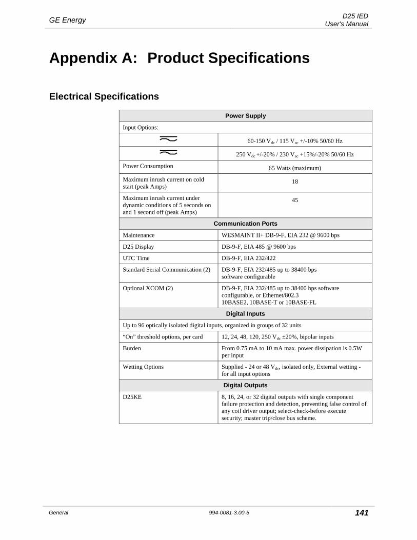
GE Energy D25 IED User's Manual
General 994-0081-3.00-5 141
Appendix A: Product Specifications
Electrical Specifications
Power Supply
Input Options:
60-150 Vdc / 115 Vac +/-10% 50/60 Hz
250 Vdc +/-20% / 230 Vac +15%/-20% 50/60 Hz
Power Consumption 65 Watts (maximum)
Maximum inrush current on cold start (peak Amps)
18
Maximum inrush current under dynamic conditions of 5 seconds on and 1 second off (peak Amps)
45
Communication Ports
Maintenance WESMAINT II+ DB-9-F, EIA 232 @ 9600 bps
D25 Display DB-9-F, EIA 485 @ 9600 bps
UTC Time DB-9-F, EIA 232/422
Standard Serial Communication (2) DB-9-F, EIA 232/485 up to 38400 bps software configurable
Optional XCOM (2) DB-9-F, EIA 232/485 up to 38400 bps software configurable, or Ethernet/802.3 10BASE2, 10BASE-T or 10BASE-FL
Digital Inputs
Up to 96 optically isolated digital inputs, organized in groups of 32 units
“On” threshold options, per card 12, 24, 48, 120, 250 Vdc ±20%, bipolar inputs
Burden From 0.75 mA to 10 mA max. power dissipation is 0.5W per input
Wetting Options Supplied - 24 or 48 Vdc, isolated only, External wetting - for all input options
Digital Outputs
D25KE 8, 16, 24, or 32 digital outputs with single component failure protection and detection, preventing false control of any coil driver output; select-check-before execute security; master trip/close bus scheme.

D25 IED User's Manual GE Energy
142 994-0081-3.00-5 General
Electrical Specifications, Continued
Digital Outputs (continued)
Output Relay Contacts:
D25KE modules 1 From A
Maximum Switching Power 60 W (resistive) or 125 VA (resistive)
Maximum Switching Voltages:
D25KE DB-25 75 Vdc or 50 Vac
D25KE FACE-40 120 Vdc
Maximum Switching Currents:
D25KE 2 A
Maximum Carrying Currents:
D25KE 2 A
Interposing Relay Option
Groups of eight digital outputs can be directly interfaced to D20 KI modules
Digital Outputs – High Current Module
D25HC KE 32 isolated digital outputs with single component failure protection and detection, preventing false control of any coil driver output; select-check-before execute security; 8 outputs with optional current supervision seal-in function
Output Relay Contacts 8x 1 From C; 16x 1 Form A and 8x 1 Form A with optional current seal-in function
Maximum Make Current 10A for 5 sec
Maximum Break Current 10A @ 28 Vdc;; ; 0.85A @ 60 Vdc; 0.45A @ 120 Vdc; 0.3A @ 300 Vdc
Maximum Switching Voltages 300 Vdc or 300 Vac
Continuous Carry Current 4A
Current Sensing Level for Seal-in Function
Min 60mA; max 200mA
Simultaneously Operated Outputs Maximum 16, include max 4 with current supervision
Auxiliary Digital Outputs
Three single digital outputs for System Fail indication, Radio Keying and Auxiliary Digital output
System Fail Relay Contacts 1 Form B
Other Aux. Output Relay Contacts 1 Form A
Maximum Switching Power 60 W (resistive)
Maximum Switching Voltage 75 Vdc or 50 Vac
Maximum Switching Current 2 A
Maximum Carrying Current 2 A

GE Energy D25 IED User's Manual
General 994-0081-3.00-5 143
Electrical Specifications, Continued
DC Analog Inputs
16 optically isolated differential inputs
Measurement Range 120% of nominal
Overload Voltage ±30 Vdc (NM) continuous ±200 Vdc (CM) continuous
Nominal Voltage Input Range ±5 Vdc
Voltage Input Impedance Greater than 10 MΩ
Nominal Current Input Range Options
±1 mA, ±5 mA, ±10 mA, or ±20 mA
Current Input Burden 5k to 250Ω (1 to 20 mA)
AC Analog Measurement
Direct AC analog inputs from CTs and PTs. One to six 3-phase circuits. 15 AC analog inputs organized in groups of three (3) inputs, transformer isolated
Line Frequency 50/60 Hz, nominal ±5 Hz
AC Voltage Inputs
Nominal PT input options 63.5 Vrms 69.3 Vrms 110 Vrms 120 Vrms 220 Vrms
Measurement Range 0% to 250% of nominal
Overload Voltage 250% of nominal continuous 350% of nominal for one (1) minute
Burden Less than 0.1 VA
AC Current Inputs (Standard)
Nominal CT Input Options 1 Arms 5 Arms
Measurement and DFR Range 2% to 1600% of nominal, asymmetrical
Thermal Overload 4 times nominal current continuous 30 times nominal current 10 seconds 100 times nominal current 1 second Note: continuous over-current may affect the
accuracy of the current values.
Refer to the appropriate PRPI for the accuracy specifications under over-current conditions.
Burden Less than 0.1 VA @ nominal input current

D25 IED User's Manual GE Energy
144 994-0081-3.00-5 General
Electrical Specifications, Continued
AC Current Inputs (42x Nominal)
Nominal CT Input Options 1 Arms or 5 Arms
DFR Range 42x nominal
Measurement Range 2% to 1600% of nominal, asymmetrical
Thermal Overload 4 times nominal current continuous 30 times nominal current 10 seconds 100 times nominal current 1 second Note: continuous over-current may affect the
accuracy of the current values.
Refer to the appropriate PRPI for the accuracy specifications under over-current conditions.
Burden Less than 0.1 VA @ nominal input current
LCD Display
Operating temp. -20 – 70 degrees Celsius
LCD Display size 2.75” x 7.4”
Graphic Display Panel
Operating temp. 0 – 50 degrees Celsius
LCD Display Resolution 320 x 240 pixels 0.36 mm pitch
Color blue/black on white background
Viewable area 4.76” x 3.58”
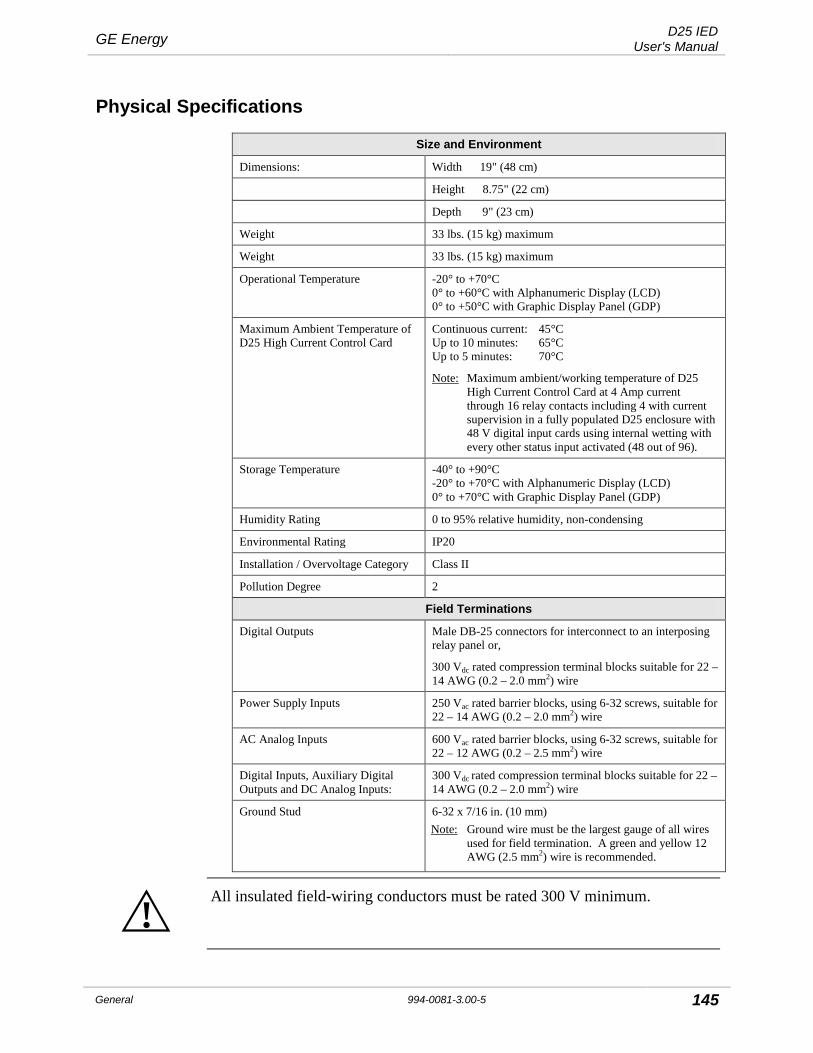
GE Energy D25 IED User's Manual
General 994-0081-3.00-5 145
Physical Specifications
Size and Environment
Dimensions: Width 19" (48 cm)
Height 8.75" (22 cm)
Depth 9" (23 cm)
Weight 33 lbs. (15 kg) maximum
Weight 33 lbs. (15 kg) maximum
Operational Temperature -20° to +70°C 0° to +60°C with Alphanumeric Display (LCD) 0° to +50°C with Graphic Display Panel (GDP)
Maximum Ambient Temperature of D25 High Current Control Card
Continuous current: 45°C Up to 10 minutes: 65°C Up to 5 minutes: 70°C
Note: Maximum ambient/working temperature of D25 High Current Control Card at 4 Amp current through 16 relay contacts including 4 with current supervision in a fully populated D25 enclosure with 48 V digital input cards using internal wetting with every other status input activated (48 out of 96).
Storage Temperature -40° to +90°C -20° to +70°C with Alphanumeric Display (LCD) 0° to +70°C with Graphic Display Panel (GDP)
Humidity Rating 0 to 95% relative humidity, non-condensing
Environmental Rating IP20
Installation / Overvoltage Category Class II
Pollution Degree 2
Field Terminations
Digital Outputs Male DB-25 connectors for interconnect to an interposing relay panel or,
300 Vdc rated compression terminal blocks suitable for 22 – 14 AWG (0.2 – 2.0 mm2) wire
Power Supply Inputs 250 Vac rated barrier blocks, using 6-32 screws, suitable for 22 – 14 AWG (0.2 – 2.0 mm2) wire
AC Analog Inputs 600 Vac rated barrier blocks, using 6-32 screws, suitable for 22 – 12 AWG (0.2 – 2.5 mm2) wire
Digital Inputs, Auxiliary Digital Outputs and DC Analog Inputs:
300 Vdc rated compression terminal blocks suitable for 22 – 14 AWG (0.2 – 2.0 mm2) wire
Ground Stud 6-32 x 7/16 in. (10 mm) Note: Ground wire must be the largest gauge of all wires
used for field termination. A green and yellow 12 AWG (2.5 mm2) wire is recommended.
!
All insulated field-wiring conductors must be rated 300 V minimum.

D25 IED User's Manual GE Energy
146 994-0081-3.00-5 General
Storage and Battery
Environmental Tolerance
As a general rule, always store the D25 IED in an environment compatible with operating conditions
Temperature: Standard -40° to +90°C
Alphanumeric Display (LCD) -20° to +70°C
Graphic Display Panel 0° to +70°C with (GDP)
Relative humidity 0 to 95%, non-condensing
Note: Exposure to excessive temperature or other extreme environmental conditions might cause damage and/or unreliable operation
Battery
A Panasonic BR2/3A, or equivalent, battery will maintain the contents of the NVRAM for over 5 years, if system power is applied.
A Tadiran Lithium battery, TL-2100S or equivalent, will maintain the contents of the NVRAM on the 20 MB Memory Expansion board for over 1 year at 25°C. It will maintain the contents of the NVRAM for 15 years with system power applied
Note: If the D25 is to be stored for extended periods, you may wish to disconnect the battery. The Battery status is provided during the D25 start-up sequence.

GE Energy D25 IED User's Manual
General 994-0081-3.00-5 147
Appendix B: Engineering Value Calculations
Conversion Formulas
Interpreting Data Values
This appendix provides information to assist the user in interpreting the data point values seen in WESMAINT. • DC Analog Input Engineering value Calculation Formulas • AC Analog and Accumulator Input Engineering value Calculation Formulas
Table: DC Analog Formulas
Formulas for converting DC analog input values from raw system database counts to engineering units:
Input Type Engineering Value Calculation Engineering
Unit
Voltage 01032767 .orcalingFactAnalInputS
ltageNomInputVoRawCount∗∗
∗
V
Current 01032767 .orcalingFactAnalInputS
rrentNomInputCuRawCount∗∗
∗
mA

D25 IED User's Manual GE Energy
148 994-0081-3.00-5 General
Conversion Formulas, Continued
Table: AC Analog & Accumulator Formulas
Formulas for converting AC analog and accumulator input values from raw system database counts to engineering units:
Input Type Engineering Value Calculation Engineering Unit
Voltage: (RMS, Symmetrical
Components) 000132768
52,
VnomRawCount.∗
∗∗
Vnom = Nominal input voltage
kV
Current: (RMS, Symmetrical
Components) 32768
16 InomRawCount ∗∗
Inom = Nominal input current
A
Phase Angle 32768
360 RawCount∗ Degrees
Frequency 50 Hz Circuit ( ) 4532766
101+
∗−RawCount Hz
60 Hz Circuit ( ) 5532766
101+
∗−RawCount
Power (per phase): Active, Reactive,
Apparent 000000132768750 ,,.InomVnomRawCount
∗∗∗∗
MW, MVAr, MVA
Power (per circuit): Active, Reactive,
Apparent 000000132768
4,,
InomVnomRawCount∗
∗∗∗ MW,
MVAr, MVA
Energy (per phase): Active, Reactive,
Apparent 0001327687503600
65536,.Freq
InomVnomRawCount∗∗∗∗∗∗∗
kWh, kVArh, kVAh
Energy (per circuit): Active, Reactive,
Apparent 0001327683600
465536,Freq
InomVnomRawCount∗∗∗
∗∗∗∗ kWh,
kVArh, kVAh
THD, Voltage Unbalance 32768
100 RawCount∗ %
Power Factor 32767
RawCount
References RawCount

GE Energy D25 IED User's Manual
General 994-0081-3.00-5 149
Appendix C: Ordering Information
The latest D25 ordering guide, which includes a spare parts list and accessories, is available for download from the GE Energy website:
http://www.gepower.com/prod_serv/products/substation_automation/en/controllers/d25.htm

D25 IED User's Manual GE Energy
150 994-0081-3.00-5 General
MODIFICATION RECORD
VERSION REV. DATE AUTHOR CHANGE DESCRIPTION
1.00 1 March 12, 2003 S. Poda Created
2.00 0 May 12, 2006 M. Haska Merged with 994-0076, removed old information.
2.00 1 Dec 6, 2006 TCS-Sravanthi Corrected Wetting options for High Voltage Digital Input cards. Clarify Case # 20061020-0254
Changed part numbers 450-0116 to 450-0107 and 450-0117 to 450-0108. Clarify Case # 20061120-0372-1.
Added note for serial input resistance in Communication ports section. Clarify Case # 20061102-0363.
Added note (IRIG-B is received on CTS Port) to the IRIG-B notes in Communication ports section. Clarify Case # 20061027-0326-2.
2.00 2 Oct. 23, 2007 M. Haska Updated ordering guide power supply option (1).
2.00 3 June 4, 2008 M. Haska Updated p. 118 per CC#20080529-0279.
3.00 0 February 23, 2009 A. Poda
A. Shoari Nejad
S. Poda
Added High Current Control Card Updated Ordering Information, Obsolete parts
Added product bulletin information
Corrected Fuse Specifications in Fuse Replacement section
3.00 1 March 24, 2009 S. Poda Removed D25KE FACE-40 specification row (p. 144)
Added Max Ambient Temp Spec for HCKE (p. 147)
Updated Chapter 9: Troubleshooting.

GE Energy D25 IED User's Manual
General 994-0081-3.00-5 151
AUTHENTICATION RECORD
VERSION REV. DATE AUTHOR SCOPE OF AUTHENTICATION
2.00 1 Jan. 31, 2007 H. Kozlow Change Description: Corrected Wetting options for High Voltage Digital Input cards. Clarify Case # 20061020-0254
Change Description: Changed part numbers 450-0116 to 450-0107 and 450-0117 to 450-0108. Clarify Case # 20061120-0372-1.
Change Description: Added note for serial input resistance in Communication ports section. Clarify Case # 20061102-0363.
Change Description: Added note (IRIG-B is received on CTS Port) to the IRIG-B notes in Communication ports section. Clarify Case # 20061027-0326-2.
2 Oct. 23, 2007 H. Kozlow Updated ordering guide power supply option (1).
3 June 4, 2008 H. Kozlow Updated p. 118 per CC#20080529-0279.
3.00 0 March 5, 2009 H. Kozlow Added Warning to product safety (chapter 1, p. 12)
Added LCD panel overview section and Graphics Display Panel overview (chapter 2, p. 16 – 22)
Updated control output section (p. 31) with entries related to D25 High Current KE Control Card
Added D25HC KE with WESDAC Type III DAC entries to control section (p. 52 – 55)
Added description related to D25 HCKE card (chapter 6 p. 94 – 96)
Added "Using Current-Monitored Digital Outputs" section (chapter 6, p. 97 – 98)
Added procedure "Recycling of Batteries" (p. 103)
Added warning related to D25 HCKE card replacement procedure (p. 106 and p. 123)
Added Note related to D25 HCKE use (p. 137)
Added Electrical specification for D25 High Current KE Control Card (p. 144)
1 March 24, 2009 H. Kozlow Removed D25KE FACE-40 specification row (p. 144)
Added Max Ambient Temp Spec for HCKE (p. 147)
2 July 21, 2011 R. Rees Updated Technical Support and Customer Service contact information.
3 Feb 17, 2012 R. Rees Added caution note for installing the Memory Expansion Card.
4 June 19, 2012 R. Rees Replaced Ethernet XCOM Card section with D25 Ethernet Card 100Base section.
5 July 4, 2012 R. Rees Added SQL and Jabber provision note to section: D25 Ethernet Card 100Base
