d operati ual a n ma stallatio - cloud object storage · the simplified theory of this ... at0623 6...
TRANSCRIPT
"AT" SERIES ELECTRIC HOT WATER BOILERSFOR FORCED HOT WATER
InST
ALLA
TIO
n M
AnUA
L An
D O
PERA
TIn
G In
STRU
CTIO
nS
P/N I80, Rev. B [03/09]
An ISO 9001-2000 Certified Company
R
ARGO (Technical Support)2201 Dwyer AvenueUtica, NY 13501
(Corporate Sales)85 Middle RoadDunkirk, NY 14048www.argocontrols.com

2
INSTALLATION MANUAL AND OPERATING INSTRUCTIONS
TABLE OF CONTENTS
Safety Symbols .................................................... 2Warnings .............................................................. 3Introduction ........................................................... 3Product Description .............................................. 3Voltage Rating Tables ........................................... 4Installation Procedure ........................................... 5Design of Water Circulating System ..................... 6Connecting Supply and Return Piping.................. 6Connecting Electrical Power Supply..................... 8Wiring Diagrams ................................................. 11Thermostat Installation ....................................... 15Startup and Seasonal Maintenence ................... 15Troubleshooting .................................................. 16Maintenance ...................................................... 17Parts List - 2 Element Electric Boilers ............... 18Parts List - 4 Element Electric Boilers ................ 19Additional Wiring Diagrams ................................ 20Modular Boiler Piping ......................................... 23Troubleshooting .................................................. 24"AT" Series Boiler Dimensions ........................... 27Homeowner's Reference Table .......................... 28
KEEP THIS MANUAL NEAR BOILERRETAIN FOR FUTURE REFERENCE
16027 Tested For 30 LBS.ASME
Working Pressure
! !
! !
! !
SAFETY SYMBOLS
The following defined symbols are used throughout this manual to notify the reader of potential hazards of varying risk levels.
DANGER
Indicates an imminently hazardous situation which, if not avoided, WILL result in death or serious injury.
WARNING
Indicates a potentially hazardous situation which, if not avoided, COULD result in death or serious injury.
CAUTION
Indicates a potential hazardous situation which, if not avoided, MAY result in minor or moderate injury. It may also be used to alert against unsafe practices.
IMPORTANT: Read the following instructions COMPLETELY before installing!!

3
INTRODUCTION
This manual is intended to familiarize the installer and user of the Electric Hydronic Block with its installation, operation and maintenance so as to assure its normal trouble free operation.
Argo electric boilers are designed and manufactured with quality components for maximum life and durability and require minimum service. To insure a satisfactory installation it is imperative that the instructions be followed carefully before operating the heating system. Failure to do so may result in breach of warranty.
PRODUCT DESCRIPTION
The Electric Hydronic Block is a heating device that converts electrical energy to heat energy through the medium of water. The simplified theory of this conversion is as follows:
Electrical Energy x Conversion Factor = Energy– Or –
Kilowatts Of Electricity Used Per Hour x 3412 = British Thermal Units (Btuh) Available Per Hour For Heating.
This information is the basis used to establish Elec-tric Hydronic Block ratings (See Table 1 on page 4). Since the conversion process requires no combus-tion, the boiler operates with the highest possible efficiency.
The Electric Hydronic Block is constructed with a cast iron boiler that conforms to the American Society of Mechanical Engineers (ASME) Boiler & Pressure Vessel Code. The interior design allows just enough water to be present for proper heating element operation - no excess water is stored which would cause undersirable thermal losses and longer recovery times.
The control system is assembled in a modular pack-age thus keeping the overall size and weight of the Electric Hydronic Block to a minimum. The construc-tion of the entire Electric Hydronic Block conforms to Canadian Standards Association (CSA) Standards for Safety for Electric Boilers.
! !
! !
WARNINGS
WARNING
1. BOILER SIzING IS CRUCIAL. The maximum hourly heat loss for each heated space should be calculated in accordance with the proce-dures describes in The Hydronics Institute (I=B=R) manual H-22 (Heat Loss Calculation Guide), or by any other method which is suit-able for local conditions, provided the results are in substantial agreement. Select the ap-propriate boiler based on accurate heat loss calculation. DO NOT OvERSIzE THE BOILER, AS SIzING IS CRITICAL FOR IN-FLOOR RADI-ANT HEAT APPLICATIONS.
2. Keep boiler area clear and free from combus-tible materials, gasoline and other flammable vapors and liquids.
3. DO NOT obstruct air openings to the boiler room.
4. Modification, substitution or elimination of factory equipped, supplied or specified components may result in property damage, personal injury or the loss of life.
5. TO THE OWNER: Installation and service of this boiler must be performed by a qualified installer.
6. TO THE INSTALLER: Leave all instructions with the boiler for future reference.
7. When this product is installed in the Com-monwealth of Massachusetts the installation must be performed by a licensed plumber or licensed gas fitter.*
* In other areas, consult your local codes.
WARNING
All installations of boilers should be done only by a qualified expert and in accordance with the appropriate Argo manual. Installing a boiler or any other electric appliance with improper methods or materials may result in serious injury or death due to fire.

4
The following important product information is located on the cabinet cover:
• Model Number• Manufacturer's Serial Number• BTU Rating• Heating Element Ratings• Water Pressure & Temperature Limits• CSA Listing• ASME Stamp• Total Amps• Clearance
ARGO Electric Boilers are controlled by a electronic temperature controller. The controller controls the boiler water temperature with multiple stages and turns stages on based on the heating demand, and the preset boiler outlet water temperature. The controller also can control 120Vac circulating pumps rated up to 5A. When the thermostat calls for heat, the controller will operate the boiler to regulate the water temperature at a pre-selected set point. The system pump is on whenever there is a thermostat calling for heat.
vOLTAGE RATING TABLES
A - STANDARD 240V RATINGS“AT” Series - 2 Element Boiler
Model
Boiler Size
Nominal KW
Operating voltage
(AC)
Net Heat
Output BTU/Hr.
Power Input Watts
Total Heating Element
Amperage
Number of Elements
Element Size
(Watts)
Maximum Amperage Per Leg (1)
Suggested Wire Size
(AWG) (2)(3)
Suggested Breaker Size (Amps) (3)
AT0623 6 240 20,472 6,000 25.0 2 3,000 31.0 8 40AT0824 8 240 27,296 8,000 33.3 2 4,000 39.3 6 50AT1025 10 240 34,120 10,000 41.7 2 5,000 47.7 6 60AT1226 12 240 40,944 12,000 50.0 2 6,000 56.0 4 70
“AT” Series - 4 Element BoilerAT1243 12 240 40,944 12,000 50.0 4 3,000 56.0 4 70AT1644 16 240 54,592 16,000 66.7 4 4,000 72.7 3 90AT2045 20 240 68,240 20,000 83.3 4 5,000 89.3 2 100AT2446 24 240 81,888 24,000 100.0 4 6,000 106.0 1 125
B - DE-RATED 208V RATINGS“AT” Series - 2 Element Boiler
Model
Boiler Size
Nominal KW
Operating voltage
(AC)
Net Heat
Output BTU/Hr.
Power Input Watts
Total Heating Element
Amperage
Number of Elements
Element Size
(Watts)
Maximum Amperage Per Leg (1)
Suggested Wire Size
(AWG) (2)(3)
Suggested Breaker Size (Amps) (3)
AT0623 6 208 15,377 4,507 21.7 2 3,000 27.7 8 40AT0824 8 208 20,502 6,009 28.9 2 4,000 34.9 8 50AT1025 10 208 25,628 7,511 36.1 2 5,000 42.1 6 60AT1226 12 208 30,753 9,013 43.3 2 6,000 49.3 6 70
“AT” Series - 4 Element BoilerAT1243 12 208 30,753 9,013 43.3 4 3,000 49.3 6 70AT1644 16 208 41,005 12,018 57.8 4 4,000 63.8 4 90AT2045 20 208 51,256 15,022 72.2 4 5,000 78.2 3 100AT2446 24 208 61,507 18,027 86.7 4 6,000 92.7 1 125(1) Allows for 6A control and accessory load in addition to heat load(2) Type “THW” wire, copper only, check local codes (Sizes taken from C.E.C Table 2 & N.E.C. Table 310-16.)(3) Actual wire and breakers need to be sized based on specific installation requirements in accordance with National Electrical Code (NEC), Canadian Electrical Code (CEC), and local codes (where applicable).
PRODUCT DESCRIPTION continued

5
! !
INSTALLATION PROCEDURE
Improper installation, adjustment, alteration, service or maintenance can cause injury or property damage.
1. The installation must conform to the requirements of the authority having jurisdiction or, in absence of such requirements, to the latest revision of the Canadian Electrical Code, CSA C22.1 Part 1, and/or any local regulations in Canada, or the National Electrical Code, ANSI/NFPA to (Latest Edition) and/or any local regulations and codes in the USA. Reference should also be made to local Electric utility regulations and other codes in effect in the area in which the installation is to be made.
2. Where required by the authority having jurisdiction, the installation must conform to American Society of Mechanical Engineers Safety Code for Controls and Safety Devices for Automatically Fired Boilers, ANSI/ASME No. CSD-1.
3. The Boiler is intended for indoor installation only and not subject to water spray or leakage.
CAUTION
Do not install boiler UNDER potential water source.
(RULE OF THUMB: Water Under Wires.)
4. Electric Hydronic Block units are provided with mounting brackets for easy wall mounting. The unit may be mounted directly on the wall by the use of lag screws or anchor bolts through holes provided, or on a 3/4" plywood panel. On uneven walls, it is suggested that a mounting surface be provided such as two 2 x 4’s.
5. Any surface of the Electric Hydronic Block except the back shall be mounted no closer than 20 inches to the wall surface on the left and 20 inches minimum to wall surface on the right or more, depending on plumbing. Allow sufficient room from the front of the unit to a door or wall to remove cover - at least 12 inches minimum.
Install unit with a minimum clearance from top of unit to ceiling of 16 inches. If minimum requirements of space are used, it is suggested that the enclosure be exposed to some means of ventilation. The electric Hydronic Block unit must be mounted level, using the top of the back plate as a leveling point.
6. When installed in utility room, the door should be wide enough to allow the largest boiler part to enter, or to permit replacement of another appliance such as a water heater.
Minimum clearances to combustible constructions are:
TOP ...................................................16 IN.FRONT ..............................................12 IN.LEFT SIDE.........................................20 IN.RIGHT SIDE ......................................20 IN.REAR ...................................................0 IN.BOTTOM...........................................10 IN.
20”MIN
20”MIN
10”MIN
5’-3”SUGGESTEDHEIGHT FOR
EASE OFINSTALLATION
BOILER LOCATION & CLEARANCE DIMENSIONS
NOTE: Greater clearances for access should supercede fire protection clearance.

6
DESIGN OF WATERCIRCULATING SYSTEM
System should be designed as primary/secondary piping and to operate with a maximum output tem-perature of 180º F or lower and a temperature rise across the unit of 20º F or lower. Refer to tables below and Figures 2 & 3.
NOTE: To prevent condensation, the return water temperature must be higher than the room tem-perature in which the boiler is installed.
at the bottom of the unit. Reverse flow will result in a noisy operation and cause very early element failure. The drain cock is to be located at the lowest point of piping.
5. The outlet or supply pipe line to the radiation is located at the top of unit. A combination temperature pressure (altitude) gauge is provided with each unit and should be installed close to the boiler outlet. It is important that the gauge sensor be completely immersed in the flowing water so as to assure correct temperature readings. Manual or automatic water make up supply may be located in this area below. The circulator pump should be installed on the supply side (pumping away).
6. Gate valves should be installed at the locations shown in Figures 2 & 3, so that any boiler servicing requiring removal of water can be done quickly and easily. Not illustrated but also highly recommended is the installation of air vents at the high points of the hydonic system. These devices will reduce initial start up time and help avoid element burnout during the entire life of the heating system.
7. A pressure relief valve is supplied with each Electric Hydronic Block and should be installed at the location and discharge direction shown in Figure 1, using pipe nipple and elbow supplied. Piping should be added so that any water that may be discharged will not damage the boiler or other system components.
PLUMBING ANDACCESSORY
INSTALLATION
FIGURE 1
8. For further piping information refer to The Hydronics Institute (I=B=R) manual 200 (Installation Guide for Residential Hydronics).
“AT” Series - 2 Element BoilerKW Capacity Minimum Flow Rate (GPM)*
6 2.08 2.7
10 3.412 4.1
“AT” Series - 4 Element BoilerKW Capacity Minimum Flow Rate (GPM)*
12 4.116 5.520 6.824 8.2
* Flow rate based on 20°ΔT
CONNECTING SUPPLYAND RETURN PIPING
1. Maintain a minimum clearance of one inch to hot water pipes.
2. Hot water boilers installed above radiation level must be provided with a low water cutoff device either as part of the boiler or at the time of boiler installation.
NOTE: In some states a low water cutoff device (LWCO) may be required. Check your local codes.
3. When a boiler is connected to a heating system that utilizes multiple zoned circulators, each circulator must be supplied with a flow control valve to prevent gravity circulation.
NOTE: Reduced pressure back flow provender must be present under provisions required by the Environmental Protection Agency, (EPA).
4. Suggested plumbing arrangements are illustrated in Figures 2 & 3. The inlet or return pipe is located

7
PRIMARY/SECONDARY PIPING FORMULTIPLE zONING WITH zONE vALvES
FIGURE 3
PRIMARY/SECONDARY PIPING FORMULTIPLE zONING WITH CIRCULATORS
FIGURE 2
PRIMARY/SECONDARY PIPING

8
CONNECTING ELECTRICAL POWER SUPPLY
! !
WIRING THE BOILER
WARNING
DO NOT USE ALUMINUM WIRE!!
Argo Electric Hydronic Boilers are pre-wired for use with 240-volt, 3 wire, single-phase, 50/60-hertz power. Refer to Table 1B on page 4 for the reduction in boiler capacity when the line voltage is less than 240 volts.
An opening is provided in the jacket bottom panel for the field wiring, refer to the rating chart for recommended wire sizes.
All electrical wiring must be done in accordance with the Canadian Electrical Code, CSA C22.1 Part 1, and /or any local regulations and codes in Canada, or the National Electrical code, ANSI/NFPA 70 (Latest edition) and/or any local regulations and codes in USA. Verify the nameplate rating and check the related codes to properly size conductors, switches and over current protection. Several openings are provided on the bottom of the cabinet for different voltage connections. For wire connections refer to the wiring diagram on the inside of the boiler front cover. Do not use aluminum wire!!
All circuit breakers or disconnects ahead of the boiler must be OFF. If boiler contains integral breakers (depending on option), it is recommended that they are also turned off at this time. Remove the boiler front cover by removing 4 screws from the top and sides.
When a boiler is used in a zoned system, the zone valves must be powered from an independent source and have electrically isolated end switches or isolating relays wired in parallel to the boiler thermostat terminals. Do not attempt to power zone valves from the transformer in the boiler control system!!
WIRING ON CONTROL
PUMP: Connect only 120 Vac 1/6 HP (maximum) pump to terminals C1(L) and C2(N) on the controller. Strip wire ends before inserting into terminal block. Tighten terminal screws. Do not use a pump requiring greater than 5 amps!!
THERMOSTAT: Connect thermostat or zone valve end switch to terminals TT and TT (Figure 4). Do not apply an external power source to these terminals!! Strip wire ends before inserting into terminal block. Tighten terminal screw clamps.
LIMIT CONTROL OPERATION
1. When the boiler water temperature exceeds the high limit setting on the aquastat, all heating element control relays are instantly de- energized. Circulator continues to operate until call for heat ends. When water temperature drops below aquastat re-set differential, heating element power relays close as per time delay sequence.
2. MAIN POWER SUPPLY: Depending on model designation, the electric Hydronic Block may be energized by the following alternating current service entrances: 240 volt single phase 50 or 60 cycle 3 wire. The wire size required may be selected from Table 1. The sizes listed for various capacity units include total amperes necessary to operate elements, circulator and zone valves where used. Wire sizes specified conform to the Canadian Electrical Code (Canada) or National Electric Code (USA) and include derating for
FIGURE 4
FIGURE 5

9
ampacity and temperature. Use copper wire only with insulation rated for 75 °C. Check state and local requirements.
NOTE: Read the data name plate before connecting unit so that you will become familiar with the specifications. All electrical connections to the unit are provided and located for ease of proper installation.
IMPORTANT: Use only copper wire of proper size and make sure all terminations are very tight. Do not use aluminum wire!!
3. CIRCULATOR POWER SUPPLY: Terminals identified as C1(L) and C2(N) at the bottom of the control panel (Figure 5) may be used to supply one circulator pump power. The circulator motor shall not be larger than 1/6 horsepower with a maximum 5.0 amp rating. Wiring from the control panel to the pump should have insulation rated at 75°C. Circuit protection is provided by a 15 amp breaker or fuse (depending on option) on the control board.
NOTE: If the circulator pump is larger than the maximum size listed above, then a separate circulator pump relay must be provided with separate overload protection. Where more than one circulator is used for zoning, it must be installed and protected according to approved electrical codes.
CONTROL INFORMATION
CONTROL BOARD SPECIFICATIONS:
Dimensions: 5-7/8"(W) x 9-3/8" (L) x 1-5/8" (H)
Operating Control Outlet Water Tempera-ture: 90°F - 180°F (adjustable)High Limit Control Outlet Water Tempera-ture: 200°F (fixed)
Control Input voltage: 120V ac
Control Output voltage: 120V ac, 5A max. (cir-culator terminal)
POWER OUTPUT: One 120V ac pump output is switched by an onboard circulator relay. The load current is limited and must not exceed 5A.
CONTROL BOARD POWER CONSUMPTION: 0.8A max.LED DISPLAY LIGHTS (Figure 6): A total of 8 LED indicator lights display the following information:
(1) T-T (Green): LED is lit when thermostat is calling for heat.(2) Fault (Red): LED is lit/flashes when there is an operating error/safety fault.(3) Safety Switch (Green): LED is lit when there are no safety faults.(4) Circ (Green): LED is lit when circulator termi-nals are energized.(5) Heating Element#1 (Green): LED is lit when element#1 is energized.(6) Heating Element#2 (Green): LED is lit when element#2 is energized.(7) Heating Element#3 (Green): LED is lit when element #3 is energized.(8) Heating Element#4 (Green): LED is lit when element#4 is energized.
FIGURE 6
SIGNAL/CONTROL INPUTS:TT: Thermostat or zone valve end switch, switch-ing input, closed is activation.HL: High limit temperature sensors (factory in-stalled), normally closed.LWC: Low water cutoff (optional) end switch, normally closed (factory installed jumper).FLOW: Flow switch (optional) end switch, normally closed (factory installed jumper).

10
TEMPERATURE CONTROL RANGES:
Temperature: Degrees FahrenheitOperating Temperature Range:
90°F - 180°F(Factory Setting: 180°F)
Operating Temperature Differential Range: +/- 4°F - +/- 20°F(Factory Setting: 12°F)
Fixed High Limit Temperature: 200°F
OPERATING TEMPERATURE AND DIFFEREN-TIAL ADjUSTMENTS: Internal temperature poten-tiometer on the control.
CONTROL OPERATION: When the control switch is in the "On" position and all safety end switches are closed, the "Safety Switch" LED is lit. Once in operating mode, the control uses the well-mounted (RTD) sensor to continuously monitor the boiler water temperature.
When the thermostat calls for heat ("TT" LED is lit), the control will energize the circulator ("Circ" LED is lit) for 30 seconds to establish flow. Next the con-trol will measure water temperature and differential setting, perform a check for an "open" or "shorted" RTD sensor, check that all safety end switches are "closed," and check for stuck or welded element relay contacts. Next, the control will energize only one element ("Element" LED is lit) and monitor water temperature for 60 seconds. The control will energize additional elements at 30 second intervals to bring the system up to set point temperature in 5 minutes.
Once the system reaches the set point temperature and there is still a call for heat, the control will modu-late the number of elements on and off in order to maintain the set point temperature. The required number of elements which are energized is deter-mined by heating demand, which is the difference between actual boiler water temperature and set point temperature.
After the call for heat has been satisfied, the elements will be de-energized ("Element" LEDs turn off) by the control and the circulator will continue to be
energized for 3 minutes to purge the boiler. After 3 minutes the control will de-energize the circulator ("Circ" LED turns off).
If at any time during the start-up of the boiler or during operation a safety end switch opens its respective contact, the control de-energizes all elements, continues to energize the circulator, and flashes a visible fault code ("Fault" LED flashes) along with an audible fault code. (See fault codes (below)) The control has a built-in reset function.
TEMPERATURE SETTING: The water "Set point" temperature adjustment dial on the control should always be set at the designed boiler water temperature.
CONTROL MOUNTING: The control is mounted using 1/2" tall plastic standoffs. The indicator LEDs are visible through a clear polycarbonate viewing window on front cover of the boiler.
PROTECTION FROM LIqUIDS: The control and other components located within the control panel are sensitive to water and other liquids. Measures must be taken to fully protect components on panel from contact with liquids.
FAULT CODES (vISUAL/AUDIBLE):
RTD SENSOR:To confirm that the RTD sensor is functioning prop-erly, follow the steps below.1. Remove both RTD leads from the terminal block
on the boiler control board.2. Use a multimeter to take an ohm reading across
the RTD leads. A properly functioning RTD will produce a reading of approximately 1000 ohms at 70° F. A faulty RTD will read either 0 or 1 on your multimeter.
3. Replace RTD if necessary.
Number of Flashes/Pulses Description
1 Safety switch fault2 Stuck/welded element relay contact3 RTD short4 RTD open
CONTROL INFORMATION continued

11
HEAT
ING
ELEM
ENTS
EN
ERGI
ZED
(ACT
IVAT
ION
DES
ÉLÉM
ENTS
DE
CHAU
FFAG
E)
SOUR
CE P
OWER
, 240
V/60
HZ/1P
H 3-
WIR
E, B
Y OT
HERS
(SOU
RCE
DU C
OURA
NT, 2
40V/
60HZ
/1PH
3-FI
LS, O
U AU
TRES
)
EQUI
PMEN
T GR
OUND
ING
LUG
(TEN
ON D
E PR
ISE
Á LA
TER
RE D
E Ľ A
PPAR
EIL)
NNE
UTRA
L BLO
CK(B
LOC
NEUT
RE)
WHT
(BLA
NC)
WHT
/BLK
(BLA
NC/N
OIR)
BLK
(NOI
R)
NOT
USED
(NON
UTI
LISÉ)
NOT
USED
(NON
UTI
LISÉ)
L
OFF
(FER
MÉ)
120V
ACCI
RC
C1C2N
L
CIRC
N 120V
ACIN
PUT
(ENT
RÉE)
WHT
(BLA
NC)
NOT
USED
(NON
UTI
LISÉ)
NOT
USED
(NON
UTI
LISÉ)
CONT
ROL
(COM
MAND
E)
RED
(ROU
GE)
TRAN
SFOR
MER
(TRA
NSFO
RMAT
EUR)
ON(O
UVER
T)
ARGO
"AT"
ELE
CTRI
C BO
ILER
SCHE
MATI
C W
IRIN
G DI
AGRA
M2 E
LEME
NT B
OILE
R,W
ITH
POW
ER B
LOCK
WHT
/BLK
(BLA
NC/N
OIR)
WHT
(BLA
NC)
WHT
/BLK
(BLA
NC/N
OIR)
WHT
(BLA
NC)
L1H2
L2L2H1 H2
RED
(ROU
GE)
LWC
FLOW
FLOWLW
C
RED
(ROU
GE)
HLHLTTTT
FAUL
T(D
ÉFAI
LLAN
CE)
41
3
2SA
FETY
SW
ITCH
ES(IN
TERR
UPTE
URS
DE S
ÉCUR
ITÉ)
T-T
90100
WHT
/BLK
(BLA
NC/N
OIR)
L1H1
WHT
(BLA
NC)
RTD
1216
815
014
012
013
0
SETP
OINT
(RÉG
LAGE
)DI
FFER
ENTI
AL(D
IFFÉ
RENT
IEL)
420
170 180
THER
MOST
AT, B
Y OT
HERS
(THE
RMOS
TAT,
OU A
UTRE
S)16
011
0
L1
POW
ER B
LOCK
(BLO
C DE
PUI
SSAN
CE)
L2
FUSE
BLO
CK(B
LOC
DE F
USIB
LE)
WIR
E LE
GEND
/ (LÉ
GEND
E DE
S FI
LS)
- DR
Y CO
NTAC
T W
IRIN
G (P
OSE
DES
CÂBL
ES D
E CO
NTAC
T SE
C)
- 12
0 VOL
T W
IRIN
G (P
OSE
DES
CÂBL
ES 12
0 VOL
T)
- 24
0 VOL
T W
IRIN
G (P
OSE
DES
CÂBL
ES 24
0 VOL
T)-
120 V
OLT
FIEL
D W
IRIN
G (P
OSE
DES
CÂBL
ES 12
0 VOL
T SU
R EN
CHA
NTIE
R)
- 24
0 VOL
T FI
ELD
WIR
ING
(POS
E DE
S CÂ
BLES
240 V
OLT
EN C
HANT
IER)
- DR
Y CO
NTAC
T FI
ELD
WIR
ING
(POS
E DE
S CÂ
BLES
DE
CONT
ACT
SEC
EN C
HANT
IER)
(DIA
GRAM
ME S
CHÉM
ATIQ
UE D
U CÂ
BLAG
E D'
UNE
CHAU
DIÈR
E À
2 ÉLÉ
MENT
S)
HIGH
LIMI
T SA
FETY
SW
ITCH
, AUT
O RE
SET
(INTE
RRUP
TEUR
DE
SÉCU
RITÉ
DE
LIMIT
E SU
PÉRI
EURE
, RE
MISE
EN
MARC
HE A
UTOM
ATIQ
UE)
HIGH
LIMI
T SA
FETY
SW
ITCH
, AUT
O RE
SET
(INTE
RRUP
TEUR
DE
SÉCU
RITÉ
DE
LIMIT
E SU
PÉRI
EURE
, RE
MISE
EN
MARC
HE A
UTOM
ATIQ
UE)
OPTI
ONAL
FLO
W S
WIT
CH, B
Y OT
HERS
(INTE
RRUP
TEUR
DE
DÉBI
T - F
ACUL
TATI
F, OU
AUT
RES)
SOUR
CE P
OWER
, 120
V/60
HZ/1P
H , B
Y OT
HERS
(SOU
RCE
DU C
OURA
NT, 1
20V/
60HZ
/1PH,
OU
AUTR
ES)
OPTI
ONAL
LWCO
, BY
OTHE
RS(IS
POSI
TIF
D'AR
RET
EN C
AS FA
IBLE
NIV
EAU
D'EA
U -
FACU
LTAT
IF -
OU A
UTRE
S)
RTD
WAT
ER T
EMPE
RATU
RE S
ENSO
R(C
APTE
UR D
E LA
TEM
PÉRA
TURE
DE
ĽEAU
RTD
)
CIRC
ULAT
OR P
UMP,
BY O
THER
S(P
OMPE
DE
ĽACC
ELER
TEUR
, OU
AUTR
ES)
CIRC
ULAT
OR R
ELAY
(REL
AIS
DUĽA
CCEL
ERTE
UR)
FACT
ORY
INST
ALLE
D JU
MPER
S(C
ALVA
LIERS
INST
ALLÉ
ES Á
ĽUSI
NE)
ARGO
ELE
CTRO
NIC
BOILE
R CO
NTRO
L(C
OMMA
NDE
ÉLEC
TRON
IQUE
DE
LA C
HAUD
IÈRE
ARG
O)
ELEM
ENT
#1(É
LÉME
NT N
o1)
ELEM
ENT
#1 R
ELAY
S(R
ELAI
S DE
ĽÉLÉ
MENT
No1
)
ELEM
ENT
#2(É
LÉME
NT N
o2)
ELEM
ENT
#2 R
ELAY
S(R
ELAI
S DE
ĽÉLÉ
MENT
No2
)
1) L
AB
EL P
RIN
TED
ON
WH
ITE
PRES
SURE
SEN
SITI
VE
MAT
ERIA
L, W
ITH
BLA
CK
TEX
T.
NO
TE:
WIRING DIAGRAMS
FIGURE 7A

12
- DR
Y CO
NTAC
T FI
ELD
WIR
ING
(POS
E DE
S CÂ
BLES
DE
CONT
ACT
SEC
EN C
HANT
IER)
LOAD
CEN
TER
(CEN
TRE
DE C
HARG
E)
ON(O
UVER
T)
TRAN
SFOR
MER
(TRA
NSFO
RMAT
EUR)
NEUT
RAL B
LOCK
(BLO
C NE
UTRE
)
EQUI
PMEN
T GR
OUND
ING
LUG
(TEN
ON D
E PR
ISE
Á LA
TER
RE D
E Ľ A
PPAR
EIL)
WHT
(BLA
NC)
WHT
/BLK
(BLA
NC/N
OIR)
CIRC
ULAT
OR P
UMP,
BY O
THER
S(P
OMPE
DE
ĽACC
ELER
TEUR
, OU
AUTR
ES)
N
SOUR
CE P
OWER
, 240
V/60
HZ/1P
H 3-
WIR
E, B
Y OT
HERS
(SOU
RCE
DU C
OURA
NT, 2
40V/
60HZ
/1PH
3-FI
LS, O
U AU
TRES
)
120V
ACIN
PUT
(ENT
RÉE)
N
CIRC
NOT
USED
(NON
UTI
LISÉ)
CIRC
ULAT
OR R
ELAY
(REL
AIS
DUĽA
CCEL
ERTE
UR)
LN C2
C1 120V
ACCI
RC
NOT
USED
(NON
UTI
LISÉ)
OFF
(FER
MÉ)
BLK
(NOI
R)
21
LL1
L2
ARGO
"AT"
ELE
CTRI
C BO
ILER
SCHE
MATI
C W
IRIN
G DI
AGRA
M2 E
LEME
NT B
OILE
R,W
ITH
BREA
KERS
(DIA
GRAM
ME S
CHÉM
ATIQ
UE D
U CÂ
BLAG
E D'
UNE
CHAU
DIÈR
E À
2 ÉLÉ
MENT
S)
- 24
0 VOL
T FI
ELD
WIR
ING
(POS
E DE
S CÂ
BLES
240 V
OLT
EN C
HANT
IER)
- 12
0 VOL
T FI
ELD
WIR
ING
(POS
E DE
S CÂ
BLES
120 V
OLT
SUR
EN C
HANT
IER)
- 24
0 VOL
T W
IRIN
G (P
OSE
DES
CÂBL
ES 24
0 VOL
T)
- 12
0 VOL
T W
IRIN
G (P
OSE
DES
CÂBL
ES 12
0 VOL
T)
OPTI
ONAL
LWCO
, BY
OTHE
RS(IS
POSI
TIF
D'AR
RET
EN C
AS FA
IBLE
NIV
EAU
D'EA
U - F
ACUL
TATI
F - O
U AU
TRES
)
SOUR
CE P
OWER
, 120
V/60
HZ/1P
H , B
Y OT
HERS
(SOU
RCE
DU C
OURA
NT, 1
20V/
60HZ
/1PH,
OU
AUTR
ES)
OPTI
ONAL
FLO
W S
WIT
CH, B
Y OT
HERS
(INTE
RRUP
TEUR
DE
DÉBI
T - F
ACUL
TATI
F, OU
AUT
RES)
110
160
THER
MOST
AT, B
Y OT
HERS
(THE
RMOS
TAT,
OU A
UTRE
S)
ELEM
ENT
#1(É
LÉME
NT N
o1)
ELEM
ENT
#1 R
ELAY
S(R
ELAI
S DE
ĽÉLÉ
MENT
No1
)
H2
HEAT
ING
ELEM
ENTS
EN
ERGI
ZED
(ACT
IVAT
ION
DES
ÉLÉM
ENTS
DE
CHAU
FFAG
E) ARGO
ELE
CTRO
NIC
BOILE
R CO
NTRO
L(C
OMMA
NDE
ÉLEC
TRON
IQUE
DE
LA C
HAUD
IÈRE
ARG
O)
NOT
USED
(NON
UTI
LISÉ)
NOT
USED
(NON
UTI
LISÉ)
RED
(ROU
GE)
CONT
ROL
(COM
MAND
E)
T-T
SAFE
TY S
WIT
CHES
(INTE
RRUP
TEUR
S DE
SÉC
URIT
É)
100 90
180
170
204
2
31
4FA
ULT
(DÉF
AILL
ANCE
)
H1L2 L2
ELEM
ENT
#2(É
LÉME
NT N
o2)
H2
ELEM
ENT
#2 R
ELAY
S(R
ELAI
S DE
ĽÉLÉ
MENT
No2
)
L1
TT TT HL HLRE
D (R
OUGE
)
LWC
FLOW
FLOW
FACT
ORY
INST
ALLE
D JU
MPER
S(C
ALVA
LIERS
INST
ALLÉ
ES Á
ĽUSI
NE)
LWC
DIFF
EREN
TIAL
(DIF
FÉRE
NTIE
L)SE
TPOI
NT(R
ÉGLA
GE)
130
120
140
150
816
12
H1L1
RTD
RTD
WAT
ER T
EMPE
RATU
RE S
ENSO
R(C
APTE
UR D
E LA
TEM
PÉRA
TURE
DE
ĽEAU
RTD
)
WHT
(BLA
NC)
- DR
Y CO
NTAC
T W
IRIN
G (P
OSE
DES
CÂBL
ES D
E CO
NTAC
T SE
C)
RED
(ROU
GE)
HIGH
LIMI
T SA
FETY
SW
ITCH
, AUT
O RE
SET
(INTE
RRUP
TEUR
DE
SÉCU
RITÉ
DE
LIMIT
E SU
PÉRI
EURE
, RE
MISE
EN
MARC
HE A
UTOM
ATIQ
UE)
WHT
(BLA
NC)
WHT
/BLK
(BLA
NC/N
OIR)
WHT
(BLA
NC)
WHT
(BLA
NC)
WHT
/BLK
(BLA
NC/N
OIR)
WHT
/BLK
(BLA
NC/N
OIR)
WHT
(BLA
NC)
HIGH
LIMI
T SA
FETY
SW
ITCH
, AUT
O RE
SET
(INTE
RRUP
TEUR
DE
SÉCU
RITÉ
DE
LIMIT
E SU
PÉRI
EURE
, RE
MISE
EN
MARC
HE A
UTOM
ATIQ
UE)
WIR
E LE
GEND
/ (LÉ
GEND
E DE
S FI
LS)
WIRING DIAGRAMSFIGURE 7B

13
WHT
/BLK
(BLA
NC/N
OIR)
NEUT
RAL B
LOCK
(BLO
C NE
UTRE
)
WHT
/BLK
(BLA
NC/N
OIR)
WHT
(BLA
NC)
WHT
(BLA
NC)
WHT
(BLA
NC)
WHT
/BLK
(BLA
NC/N
OIR)
OFF
(FER
MÉ)
ELEM
ENT
#4(É
LÉME
NT N
o4)
WHT
(BLA
NC)
L2H4
ELEM
ENT
#4 R
ELAY
S(R
ELAI
S DE
ĽÉLÉ
MENT
No4
)
120V
ACIN
PUT
(ENT
RÉE)
NL
C1L 120V
ACCI
RC
C2N
CIRC
H4L1L2
H3
WHT
/BLK
(BLA
NC/N
OIR)
WHT
(BLA
NC)
CONT
ROL
(COM
MAND
E)
ON(O
UVER
T)
TRAN
SFOR
MER
(TRA
NSFO
RMAT
EUR)
HLT-
T
HEAT
ING
ELEM
ENTS
EN
ERGI
ZED
(ACT
IVAT
ION
DES
ÉLÉM
ENTS
DE
CHAU
FFAG
E)
H2
WHT
/BLK
(BLA
NC/N
OIR)
L1H3
ELEM
ENT
#3(É
LÉME
NT N
o3)
ELEM
ENT
#3 R
ELAY
S(R
ELAI
S DE
ĽÉLÉ
MENT
No3
)
WHT
(BLA
NC)
13
L2
2
L1H2
ELEM
ENT
#2(É
LÉME
NT N
o2)
WHT
/BLK
(BLA
NC/N
OIR)
ELEM
ENT
#2 R
ELAY
S(R
ELAI
S DE
ĽÉLÉ
MENT
No2
)
LWC
FLOW
FLOWLW
C
4FA
ULT
(DÉF
AILL
ANCE
)
SETP
OINT
(RÉG
LAGE
)
WHT
/BLK
(BLA
NC/N
OIR)
140
L2
120
130
110
90100
H1
L1H1
ELEM
ENT
#1(É
LÉME
NT N
o1)
WHT
(BLA
NC)EL
EMEN
T #1
REL
AYS
(REL
AIS
DE ĽÉ
LÉME
NT N
o1)
RTD
HLTTTT
12
4
168
150
170 180
160
20
DIFF
EREN
TIAL
(DIF
FÉRE
NTIE
L)
WHT
(NOI
R)
ARGO
"AT"
ELE
CTRI
C BO
ILER
SCHE
MATI
C W
IRIN
G DI
AGRA
M4 E
LEME
NT B
OILE
R,W
ITH
POW
ER B
LOCK
(DIA
GRAM
ME S
CHÉM
ATIQ
UE D
E LA
POS
E DE
S FI
LS D
'UNE
CHA
UDIÈ
RE À
4 ÉL
ÉMEN
TS)
SOUR
CE P
OWER
, 240
V/60
HZ/1P
H 3-
WIR
E, B
Y OT
HERS
(SOU
RCE
DU C
OURA
NT, 2
40V/
60HZ
/1PH
3-FI
LS, O
U AU
TRES
)
N
RED
(ROU
GE)
RED
(ROU
GE)
RED
(ROU
GE)
THER
MOST
AT, B
Y OT
HERS
(THE
RMOS
TAT,
OU A
UTRE
S)
WHT
/BLK
(BLA
NC/N
OIR)
WHT
(BLA
NC)
FUSE
BLO
CK(B
LOC
DE F
USIB
LE)
BLK
(NOI
R)
L2L1
POW
ER B
LOCK
(BLO
C DE
PUI
SSAN
CE)
- 24
0 VOL
T FI
ELD
WIR
ING
(POS
E DE
S CÂ
BLES
240 V
OLT
EN C
HANT
IER)
EN C
HANT
IER)
- 12
0 VOL
T W
IRIN
G (P
OSE
DES
CÂBL
ES 12
0 VOL
T)
- 24
0 VOL
T W
IRIN
G (P
OSE
DES
CÂBL
ES 24
0 VOL
T)-
120 V
OLT
FIEL
D W
IRIN
G (P
OSE
DES
CÂBL
ES 12
0 VOL
T SU
R EN
CHA
NTIE
R)
- DR
Y CO
NTAC
T W
IRIN
G (P
OSE
DES
CÂBL
ES D
E CO
NTAC
T SE
C)-
DRY
CONT
ACT
FIEL
D W
IRIN
G (P
OSE
DES
CÂBL
ES D
E CO
NTAC
T SE
C
WIR
E LE
GEND
/ (LÉ
GEND
E DE
S FI
LS)
OPTI
ONAL
FLO
W S
WIT
CH, B
Y OT
HERS
(INTE
RRUP
TEUR
DE
DÉBI
T - F
ACUL
TATI
F, OU
AUT
RES)
OPTI
ONAL
LWCO
, BY
OTHE
RS(IS
POSI
TIF
D'AR
RET
EN C
AS FA
IBLE
NIV
EAU
D'EA
U -
FACU
LTAT
IF -
OU A
UTRE
S)
SOUR
CE P
OWER
, 120
V/60
HZ/1P
H , B
Y OT
HERS
(SOU
RCE
DU C
OURA
NT, 1
20V/
60HZ
/1PH,
OU
AUTR
ES)
EQUI
PMEN
T GR
OUND
ING
LUG
(TEN
ON D
E PR
ISE
Á LA
TER
RE D
E Ľ A
PPAR
EIL)
RTD
WAT
ER T
EMPE
RATU
RE S
ENSO
R(C
APTE
UR D
E LA
TEM
PÉRA
TURE
DE
ĽEAU
RTD
)
HIGH
LIMI
T SA
FETY
SW
ITCH
, AUT
O RE
SET
(INTE
RRUP
TEUR
DE
SÉCU
RITÉ
DE
LIMIT
E SU
PÉRI
EURE
, RE
MISE
EN
MARC
HE A
UTOM
ATIQ
UE)
HIGH
LIMI
T SA
FETY
SW
ITCH
, AUT
O RE
SET
(INTE
RRUP
TEUR
DE
SÉCU
RITÉ
DE
LIMIT
E SU
PÉRI
EURE
, RE
MISE
EN
MARC
HE A
UTOM
ATIQ
UE)
FACT
ORY
INST
ALLE
D JU
MPER
S(C
ALVA
LIERS
INST
ALLÉ
ES Á
ĽUSI
NE)
ARGO
ELE
CTRO
NIC
BOILE
R CO
NTRO
L(C
OMMA
NDE
ÉLEC
TRON
IQUE
DE
LA C
HAUD
IÈRE
ARG
O)
SAFE
TY S
WIT
CHES
(INTE
RRUP
TEUR
S DE
SÉC
URIT
É)
CIRC
ULAT
OR R
ELAY
(REL
AIS
DUĽA
CCEL
ERTE
UR)
CIRC
ULAT
OR P
UMP,
BY O
THER
S(P
OMPE
DE
ĽACC
ELER
TEUR
, OU
AUTR
ES)
WIRING DIAGRAMSFIGURE 8A

14
SOUR
CE P
OWER
, 240
V/60
HZ/1P
H 3-
WIR
E, B
Y OT
HERS
(SOU
RCE
DU C
OURA
NT, 2
40V/
60HZ
/1PH
3-FI
LS, O
U AU
TRES
)
NEUT
RAL B
LOCK
(BLO
C NE
UTRE
)
WHT
/BLK
(BLA
NC/N
OIR)
WHT
(BLA
NC)
N
WHT
(BLA
NC)
WHT
/BLK
(BLA
NC/N
OIR)
WHT
(BLA
NC)
WHT
(BLA
NC) EL
EMEN
T #4
REL
AYS
(REL
AIS
DE ĽÉ
LÉME
NT N
o4)
WHT
/BLK
(BLA
NC/N
OIR)
ELEM
ENT
#4(É
LÉME
NT N
o4)
OFF
(FER
MÉ)
N C212
0VAC
CIRC
L C1H4
L2
LN 12
0VAC
INPU
T(E
NTRÉ
E)
TRAN
SFOR
MER
(TRA
NSFO
RMAT
EUR)
H3L2 L1
H4CI
RC
ON(O
UVER
T)
CONT
ROL
(COM
MAND
E)
BLK
(NOI
R)
ARGO
"AT"
ELE
CTRI
C BO
ILER
SCHE
MATI
C W
IRIN
G DI
AGRA
M4 E
LEME
NT B
OILE
R,W
ITH
BREA
KERS
13
2 L2
4 L1ARGO
LOAD
CEN
TER
(CEN
TRE
DE C
HARG
E AR
GO)
THER
MOST
AT, B
Y OT
HERS
(THE
RMOS
TAT,
OU A
UTRE
S)
RED
(ROU
GE)
T-T
HL
ELEM
ENT
#2 R
ELAY
S(R
ELAI
S DE
ĽÉLÉ
MENT
No2
)
ELEM
ENT
#3 R
ELAY
S(R
ELAI
S DE
ĽÉLÉ
MENT
No3
)
WHT
/BLK
(BLA
NC/N
OIR)
ELEM
ENT
#3(É
LÉME
NT N
o3)
ELEM
ENT
#2(É
LÉME
NT N
o2)
H2HE
ATIN
G EL
EMEN
TS
ENER
GIZE
D(A
CTIV
ATIO
N DE
S ÉL
ÉMEN
TS D
E CH
AUFF
AGE)
H3L1
RED
(ROU
GE)
H2L1
FAUL
T(D
ÉFAI
LLAN
CE)
42
L2
31
LWC
FLOW
FLOWLW
C
ELEM
ENT
#1 R
ELAY
S(R
ELAI
S DE
ĽÉLÉ
MENT
No1
)
WHT
(BLA
NC)
ELEM
ENT
#1(É
LÉME
NT N
o1)
DIFF
EREN
TIAL
(DIF
FÉRE
NTIE
L)H1
L1SE
TPOI
NT(R
ÉGLA
GE)
20
160 18
017
0
150
816
4
12
H1
100 9011
0
130
120
L2
140
TT TT HL
RTD
WHT
(NOI
R)
WHT
/BLK
(BLA
NC/N
OIR)
WHT
(BLA
NC)
WHT
/BLK
(BLA
NC/N
OIR)
WHT
/BLK
(BLA
NC/N
OIR)
WHT
(BLA
NC)
WHT
/BLK
(BLA
NC/N
OIR)
WHT
(BLA
NC)
RED
(ROU
GE)
WIR
E LE
GEND
/ (LÉ
GEND
E DE
S FI
LS)
- DR
Y CO
NTAC
T W
IRIN
G (P
OSE
DES
CÂBL
ES D
E CO
NTAC
T SE
C)
- 12
0 VOL
T W
IRIN
G (P
OSE
DES
CÂBL
ES 12
0 VOL
T)
- 24
0 VOL
T W
IRIN
G (P
OSE
DES
CÂBL
ES 24
0 VOL
T)-
120 V
OLT
FIEL
D W
IRIN
G (P
OSE
DES
CÂBL
ES 12
0 VOL
T SU
R EN
CHA
NTIE
R)
- 24
0 VOL
T FI
ELD
WIR
ING
(POS
E DE
S CÂ
BLES
240 V
OLT
EN C
HANT
IER)
(DIA
GRAM
ME S
CHÉM
ATIQ
UE D
U CÂ
BLAG
E D'
UNE
CHAU
DIÈR
E À
4 ÉLÉ
MENT
S)
- DR
Y CO
NTAC
T FI
ELD
WIR
ING
(POS
E DE
S CÂ
BLES
DE
CONT
ACT
SEC
EN C
HANT
IER)
EQUI
PMEN
T GR
OUND
ING
LUG
(TEN
ON D
E PR
ISE
Á LA
TER
RE D
E Ľ A
PPAR
EIL)
OPTI
ONAL
FLO
W S
WIT
CH, B
Y OT
HERS
(INTE
RRUP
TEUR
DE
DÉBI
T - F
ACUL
TATI
F, OU
AUT
RES)
SOUR
CE P
OWER
, 120
V/60
HZ/1P
H , B
Y OT
HERS
(SOU
RCE
DU C
OURA
NT, 1
20V/
60HZ
/1PH,
OU
AUTR
ES)
OPTI
ONAL
LWCO
, BY
OTHE
RS(IS
POSI
TIF
D'AR
RET
EN C
AS FA
IBLE
NIV
EAU
D'EA
U -
FACU
LTAT
IF -
OU A
UTRE
S)
HIGH
LIMI
T SA
FETY
SW
ITCH
, AUT
O RE
SET
(INTE
RRUP
TEUR
DE
SÉCU
RITÉ
DE
LIMIT
E SU
PÉRI
EURE
, RE
MISE
EN
MARC
HE A
UTOM
ATIQ
UE)
HIGH
LIMI
T SA
FETY
SW
ITCH
, AUT
O RE
SET
(INTE
RRUP
TEUR
DE
SÉCU
RITÉ
DE
LIMIT
E SU
PÉRI
EURE
, REM
ISE
EN M
ARCH
E AU
TOMA
TIQU
E)
FACT
ORY
INST
ALLE
D JU
MPER
S(C
ALVA
LIERS
INST
ALLÉ
ES Á
ĽUSI
NE)
RTD
WAT
ER T
EMPE
RATU
RE S
ENSO
R(C
APTE
UR D
E LA
TEM
PÉRA
TURE
DE
ĽEAU
RTD
)
CIRC
ULAT
OR P
UMP,
BY O
THER
S(P
OMPE
DE
ĽACC
ELER
TEUR
, OU
AUTR
ES)
CIRC
ULAT
OR R
ELAY
(REL
AIS
DUĽA
CCEL
ERTE
UR)
ARGO
ELE
CTRO
NIC
BOILE
R CO
NTRO
L(C
OMMA
NDE
ÉLEC
TRON
IQUE
DE
LA C
HAUD
IÈRE
ARG
O)
SAFE
TY S
WIT
CHES
(INTE
RRUP
TEUR
S DE
SÉC
URIT
É)
WIRING DIAGRAMSFIGURE 8B

15
THERMOSTAT INSTALLATION
1. Thermostat should be installed on an inside wall about four feet above the floor.
2. NEVER install a thermostat on an outside wall.
3. Do not install a thermostat where it will be affected by sunlight, drafts, televisions, lighting fixtures, hot or cold pipes, fireplaces, or chimneys.
NOTE: Your new Argo AT Boiler will work well with all standard and most programmable set-back thermostats. In the event the programmable thermostat you use causes the boiler con-trol T-T LED to flicker on and off when there is no call for heat, your thermostat will require an external 24V power supply (transformer) and isolation relay or an Argo "AR822" control.
! !
! !
It is suggested that a qualified service agency be employed to make an annual inspection of the boiler and the heating system. They are experienced in making the inspection outlined below. In the event repairs or corrections are necessary they can make the proper changes for safe operation of the boiler.
CAUTION
Label all wires prior to disconnection when servicing controls. Wiring errors can cause improper and dangerous operation. verify proper operation after service.
After all procedures have been carefully followed and completed, the hydronic block is now ready to be put into service.
1. Check hydronic block circuit breaker or switch at the service entrance and, depending on the option, the hydronic block circuit breakers within the unit to assure that they are in the "Off" position.
WARNING
Only propylene glycol can be used in heating system to prevent freezing. Recommendation is a maximum 40% or less propylene glycol mixture to ensure proper operation of electric boiler.
! !
2. Fill the heating system with water until the pressure reaches 10-15 PSI. Check for leaks, repair if necessary, and purge all air from system.
CAUTION
Failure to vent and keep air out of the heating system will result in damage to heating elements in the hydronic block. Damage of this type is not covered by the manufacturer's warranty.
3. Set the boiler operating temperature to designed heating water temperature by adjusting the potentiometer dial located on the top center of the controller (Figure 4). Adjust arrow on temperature adjustment dial to the water temperature required.
NOTE: This boiler is also equipped with a high-limit temperature device set at 200°F as a safety limit control. The high limit temperature device has an automatic reset function and will reset at 170°F.
4. Turn on the hydronic block circuit breaker at the service entrance and/or disconnect switch and, depending on the option, the 15 amp circuit breaker on the hydronic block.
5. Set one thermostat above room temperature. The circulator pump will now operate.
4. Instructions for final adjustment of the thermo-stat (adjusting heating anticipator, calibration, etc.) are packaged with the thermostat. Recom-mended setting for the heating anticipator is 0.1 amps.
THERMOSTAT INSTALLATION
STARTUP AND SEASONAL MAINTENANCE

16
8. When the thermostat calls for heat, the circulator will be energized and the indicator LED will light up. Next, the heating elements are energized along with the element indicator LEDs. Once the boiler water temperature reaches the set point on the temperature adjustment dial, the controller will regulate the boiler by staging its elements. The number of elements which stay on is based on the heating demand and the set point of the boiler water temperature. After all room thermostats are satisfied with the heat, the controller de-energizes the elements one after another, and then switches the pump off after 3 minutes.
TROUBLESHOOTING
2. Close gate valves near inlet and outlet of hydronic block.
3. Close feed line valve if using automatic fill.
4. Open drain valve and allow water to drain from the boiler. Manual operation of the relief valve will assist drainage by allowing air to enter.
5. Remove cabinet cover and disconnect the two wires attached to the effected heating element.
6. Remove the four bolts that secure the heating element to the casting and pry the element loose. Take note of the markings on the element flange to assure proper reinstallation.
7. After the element has been removed, carefully clean any remaining gasket material from the casting surface. Take care not to scratch or score this surface.
8. Install new gasket and heating element while assuring that the element is correctly positioned.
9. Close relief valve. Open feed line valve and check for leaks. Open gate valves. Install heating element wires and cabinet cover.
10. Refer to "Startup and Seasonal Maintenance" for proper purging of air prior to energizing the heating elements.
6. Check system again for leaks. Allow circulator pump to run until all air has been vented from the system. A gurgling or rushing sound indicates the presence of air.
7. The hydronic block will now start to produce heat. As the water temperature increases, listen for air passing through the system. Water pressure will rise somewhat as temperature increases - this is normal as long as the pressure remains less than 25 PSI.
! !
This section is meant to assist the service technician when trouble shooting the electric boiler. As in any trouble shooting procedure, it is important to isolate as much as possible before proceeding. Often the control error codes can be a great help indentifying cause of the problem. If you suspect a wiring fault, carefully check all external wiring and wiring connec-tions following the wiring diagram label on the inside of the boiler's cover. An additional wiring diagram is included with this manual.
NOISY BOILER
1. Check water pressure of boiler. It should be be-tween 15-25 PSI.
2. Check for air within the system.
WARNING
Extreme care must taken when the boiler cover is removed. Turn “OFF” all service to the boiler. "Power On” checks should be made by a qualified electrician.
CHANGING A HEATING ELEMENT
In the event it becomes necessary to change any heating element, use the following procedure:
Problem Cause Solution
No heat when called by thermostat and “TT” LED is NOT lit
Thermostat Disconnect thermostat from control, momentarily place a jumper across terminal “TT” & “TT.” If circulator starts, trouble is in thermostat.
No power to board Confirm control’s On/Off switch is in “ON” position, check 15A circuit breaker or fuse.
“Circ” LED is NOT lit when thermostat is calling
Safety fault Check for open contact on safety’s. Confirm continuity across terminals. No power to board Confirm control’s On/Off switch is in “ON” position
“Safety Switch” LED is NOT lit when thermostat is calling
Safety fault Check for open contact on safety’s. Confirm continuity across terminals.
No power to board Confirm control’s On/Off switch is in “ON” position.
“FAULT” LED is flashing Safety fault Refer to “Fault” codes

17
1. Turn off hydronic unit circuit breaker at service entrance and/or disconnect switch.MAINTENANCE
the pressure relief valve by pulling the lever at the end of the valve until the lever is in line with the centerline of the valve. (Figure 9) Quickly close the valve to avoid losing an excessive amount of water. Repeat this procedure several times on a quick cycling basis to release any sediment that could block the relief valve pressure sensing mechanism. On heating system that use a manual water make-up or feed mechanism, be sure not to allow the system pressure to drop to 0 PSI when cycling the relief valve. Allowing this condition to occur could cause air to enter the system thus requiring a purging as described in “Startup and Seasonal Maintenance" on page 15.
! !
Because of its basic design, the hydronic block re-quires only a minimum of periodic maintenance. The preventive maintenance tasks described below are not difficult and when done a yearly basis, will aid the unit to continue its trouble free operation.
CAUTION
For safety reasons, the main power switch to the block should be turned off at the main service entrance before any work requiring removal of the cover is done. All work should be performed by qualified service personnel familiar with the unit's control system operation.
1. This boiler has been designed to provide years of trouble free performance under normal operating conditions. However, the owner should conduct a general external examination at the beginning of each heating season and at mid-heating seating season to assure good working performance is continued. In addition, a qualified service technician should examine at least once every year.
2. Do not store anything against the boiler or allow dirt or debris to accumulate in the area immediately surrounding the boiler.
3. Elements will burn out if the boiler is not filled with water when electrical power is turned on. Do not connect thermostat wire until system has been filled with water. Water should be drained out from system only when absolutely necessary to make repairs or prevent freeze-up during extended cold weather shutdown.
4. The temperature and pressure gauge on the system should be checked frequently. During normal operating conditions, pressure should be relatively stable throughout the heating season. If pressure under normal operating conditions consistently rises and falls over a period of time, this can indicate a fill valve leak, system leak, or compression tank malfunction. Leaks anywhere in the system must be repaired without delay. If any leaks or significant pressure fluctuations are observed, call for service immediately.
5. Check pressure relief discharge piping to assure that any discharged water will be properly routed to a suitable container or drain. Manually operate
If the relief valve fails to completely close after cy-cling, it will be necessary to remove it for cleaning or replacement. Turn off power to boiler and isolate the hydronic block by shutting off the inlet and outlet gate valves. Reduce the water pressure to zero by opening the relief valve. Remove the relief valve and inspect the valve disc and seat. Cleaning these parts with a clean lint free cloth may be all that is necessary. If this procedure fails then replace the valve with a new one of equal pressure and discharge rating. After installing the cleaned or new relief valve, open the gate valves and follow the procedure described in “Startup and Seasonal Maintenance" on page 15.
FIGURE 9

18
PARTS LIST - 2 ELEMENT ELECTRIC BOILERS
2 ELEMENT BOILER (Side view)
3
2
1
6 7
45
10
9
8
6 7
45
10
9
8
2 ELEMENT BOILERWith Power Block
2 ELEMENT BOILER With Breakers
4 5
6 7
10
9
8
4 5
6 7
10
9
8
2 Element Electric Boiler w/Breakers
Item Part Number Description
1 S47 Safety Limit Control (High Limit - Fixed Temp)2 G12 Gasket - Heating Element3 E13 Heating Element - 3 KW/240 Volt
E14 Heating Element - 4 KW/240 Volt E15 Heating Element - 5 KW/240 Volt E16 Heating Element - 6 KW/240 Volt
4 Z3002 Control Board - 2 Element Boiler5 240004757 RTD Sensor6 B194 Neutral Terminal Block7 L9 Ground Connection Lug8 B28 Circuit Breaker 15 A - 1 Pole - G.E. THQP 1159 B27 Circuit Breaker 40 A - 2 Pole - G.E. THQP 24010 I25 Load Center Assembly - G.E. TLM812U211 240004756 Brass Well- V1 Relief Valve - 30 PSI- 1260006 Temperature/Pressure Gauge- C57 Pressure Vessel - Cast Iron, 2 Element- Z302A Control Panel Assembly, 2 Element (Complete)
2 Element Electric Boiler w/Power Block
Item Part Number Description
1 S47 Safety Limit Control (High Limit - Fixed Temp)2 G12 Gasket - Heating Element3 E13 Heating Element - 3 KW/240 Volt
E14 Heating Element - 4 KW/240 Volt E15 Heating Element - 5 KW/240 Volt E16 Heating Element - 6 KW/240 Volt
4 Z3002 Control Board - 2 Element Boiler5 240004757 RTD Sensor6 B194 Neutral Terminal Block7 L9 Ground Connection Lug8 F3 Fuse Block, 1/4” x 1-1/4” Fuse, 300V9 F4 Fuse, 10amp, Ceramic, ABC-10
10 P8 Power Distribution Block11 240004756 Brass Well- V1 Relief Valve - 30 PSI- 1260006 Temperature/Pressure Gauge- C57 Pressure Vessel - Cast Iron, 2 Element
- Z313 Control Panel Assembly, 2 Element (Complete)
1111

19
PARTS LIST - 4 ELEMENT ELECTRIC BOILERS
2
1
3
4 ELEMENT BOILER (Side view)
4 Element Electric Boiler w/Breakers
Item Part Number Description
1 S47 Safety Limit Control (High Limit - Fixed Temp)2 G12 Gasket - Heating Element
3
E13 Heating Element - 3 KW/240 Volt E14 Heating Element - 4 KW/240 Volt E15 Heating Element - 5 KW/240 Volt E16 Heating Element - 6 KW/240 Volt
4 Z300 Control Board - 4 Element Boiler5 240004757 RTD Sensor6 B194 Neutral Terminal Block7 L9 Ground Connection Lug8 B28 Circuit Breaker 15 A - 1 Pole - G.E. THQP 1159 B27 Circuit Breaker 40 A - 2 Pole - G.E. THQP 24010 I25 Load Center Assembly - G. E. TLM812U211 240004765 Brass Well- V1 Relief Valve - 30 P.S.I.- 1260006 Pressure/Temperature Gauge- C32 Pressure Vessel - Cast Iron, 4 Element- Z304A Control Panel Assembly, 4 Element (Complete)
4 Element Electric Boiler w/Power Block
Item Part Number Description
1 S47 Safety Limit Control (High Limit - Fixed Temp)2 G12 Gasket - Heating Element3 E13 Heating Element - 3 KW/240 Volt
E14 Heating Element - 4 KW/240 Volt E15 Heating Element - 5 KW/240 Volt E16 Heating Element - 6 KW/240 Volt
4 Z300 Control Board - 4 Element Boiler5 240004757 RTD Sensor6 B194 Neutral Terminal Block7 L9 Ground Connection Lug8 F3 Fuse Block, 1/4” x 1-1/4” Fuse, 300V9 F4 Fuse, 10amp, Ceramic, ABC-1010 P8 Power Distribution Block11 240004756 Brass Well- V1 Relief Valve - 30 P.S.I.- 1260006 Pressure/Temperature Gauge- C32 Pressure Vessel - Cast Iron, 4 Element- Z314 Control Panel Assembly, 4 Element (Complete)
4 ELEMENT BOILER With Breakers
4 5
6 7
10
9
8
4 5
6 7
10
9
8
4 ELEMENT BOILERWith Power Block
4 5
6 7
10
9
8
4 5
6 7
10
9
8
11 11

20
T W R
T C 5 NC
6 NO
6
L2 L1 3 4 NO
4 NO
13 14
5 9 8 12
"AT" BOILER
THERMOSTAT SPST(2 WIRE) 24 VAC
CIR.
CIRCULATOR PUMP 120 VAC
PRIMARY
TT
TT
C1 C2
ISOLATION RELAY
CIR.
CIRCULATOR PUMP 120 VAC
SECONDARY
THERMOSTAT
"AT" BOILER
CIR.
CIRCULATORPUMP 120 VAC
TT
TT
C1 C2
"AT" BOILER
CIR.
CIRCULATOR PUMP 120 VAC
PRIMARY
TT
TT
C1 C2
SINGLE ZONE WITH CIRCULATOR 2 BOILERS
ONE SINGLE ZONE
NOTE: ABOVE NUMBERS REFER TO NUMBER DESIGNATIONS ON RELAY BASE
9 13
14
12
5
1 RELAY RELAY
BASE
4 8
DIN RAIL
ELEC
TRO
NIC
FU
SE
FACTORY INSTALLEDJUMPER
120VAC
NOTE: NUMBERS REFER TO NUMBER DESIGNATIONS ON RELAY BASE, SEE BELOW.
N
L
ARGOAR822-2II
ADDITIONAL WIRING DIAGRAMS
ITEM NUMBER DESCRIPTION
R35C Relay 10A 24VAC
240004745 Relay Base, DIN Rail Mount
240004746 DIN Rail Approximatly 2" Long

21
ADDITIONAL WIRING DIAGRAMS
"AT" BOILER
CIR.
CIRCULATOR PUMP 120 VAC
PRIMARY
TT
TT
C1 C2
"AT" BOILER
CIR.
CIRCULATOR PUMP 120 VAC
PRIMARY
TT
TT
C1 C2
CIR.
X2 X2 L N L N L N ZONE 1 ZONE 2
CIR.
120 VAC
VAC 120
TR TW TR TW
SWITCH ISOLATED
ZONE 1 ZONE 2
THERMOSTAT
SPST (2 WIRE) 24 VAC
ARGO ARM-2P
CIRCULATOR PUMPS (120 VAC)
ZONE 1 ZONE 2
THERMOSTATS
X1 X1
TWO ZONES WITH CIRCULATORS
2 BOILERS
NOTE: IF CONTROL ONLY CONTAINS ONE ISOLATED END SWITCH, PLEASE CONTACT TECHNICAL SERVICE FOR PROPER INSTALLATION.
"AT" BOILER
CIR.
CIRCULATOR PUMP 120 VAC
PRIMARY
TT
TT
C1 C2
"AT" BOILER
CIR.
CIRCULATOR PUMP 120 VAC
PRIMARY
TT
TT
C1 C2
X2 X2 ZONE 1 ZONE 2
T T
SWITCH END
ZONE 1
THERMOSTAT SPST (2 WIRE)
24 VAC
ARGO AZ-3
ZONE 2 ZONE 1 ZONE 3
T T ZONE 2
T T ZONE 3
ZONE 3
THERMOSTATS
X1 X1
THREE ZONES WITH ZONE CONTROL VALVES
2 BOILERS
ZONE
VALVE
ZONE
VALVE
ZONE
VALVE

22
ADDITIONAL WIRING DIAGRAMS
"AT" BOILER
C1 C2
CIR.
CIRCULATOR PUMP 120 VAC
TT TT
PRIMARY
X X ZONE 1 ZONE 2
T T
SWITCH END
ZONE 1
THERMOSTAT
SPST (2 WIRE)
ARGO AZ-3
ZONE 2 ZONE 1 ZONE 3
T T ZONE 2
T T ZONE 3
ZONE 3
ZONE
VALVE
ZONE
VALVE
ZONE
VALVE
THERMOSTATS
THREE ZONES WITH CONTROL VALVES
"AT" BOILER
C1 C2
CIR.
CIRCULATOR PUMP 120 VAC
TT TT
PRIMARY
X X
ZONE 1 ZONE 2
TR TW
SWITCH ISOLATED
THERMOSTAT
SPST (2 WIRE)
ARGO ARM-3P
ZONE 2 ZONE 1
ZONE 3
ZONE 3
TR TW TR TW
THERMOSTATS
L N L N L N
120 VAC
L N
CIR. CIR. CIR.
CIRCULATOR PUMPS (120 VAC)
120 VAC
THREE ZONES WITH CIRCULATORS

23
MODULAR BOILER PIPING
AR
GO
ELEC
TRIC
BO
ILER
DR
AIN
VALV
E
PRES
SURE
/TEM
PER
ATU
REG
AU
GE
PRES
SURE
RELI
EF V
ALV
E PIPE
TO
WIT
HIN
6"
OF
FLO
OR
BO
ILER
PU
MP
VALV
E
FLO
WFL
OW
12"
MA
X
FLO
ORA
RG
OEL
ECTR
ICB
OIL
ER
DR
AIN
VALV
E
PRES
SURE
/TEM
PER
ATU
REG
AU
GE
PRES
SURE
RELI
EF V
ALV
E PIPE
TO
WIT
HIN
6"
OF
FLO
OR
BO
ILER
PU
MP
VALV
E
FLO
WFL
OW
12"
MA
XFL
OW
SUPP
LY H
EAD
ER
FILL
VALV
E
VALV
E
EXPA
NSI
ON
TAN
K
AIR
SEP
ERAT
OR
AU
TOM
ATIC
AIR
VEN
TFL
OW
FLO
W
FLO
W
FLO
W
VALV
E
VALV
E
VALV
E
VALV
E
HEA
TIN
G Z
ON
E 1
HEA
TIN
G Z
ON
E 2
FLO
W
VALV
EVA
LVE
HEA
TIN
G Z
ON
E 3
MO
DU
LAR
BO
ILER
PIP
ING
CIR
CU
LATO
R PU
MP
VALV
E
SEC
ON
DA
RY
LOO
P
PRIM
ARY
LO
OP
SEC
ON
DA
RY
LOO
P
CIR
CU
LATO
R PU
MP
CIR
CU
LATO
R PU
MP
24
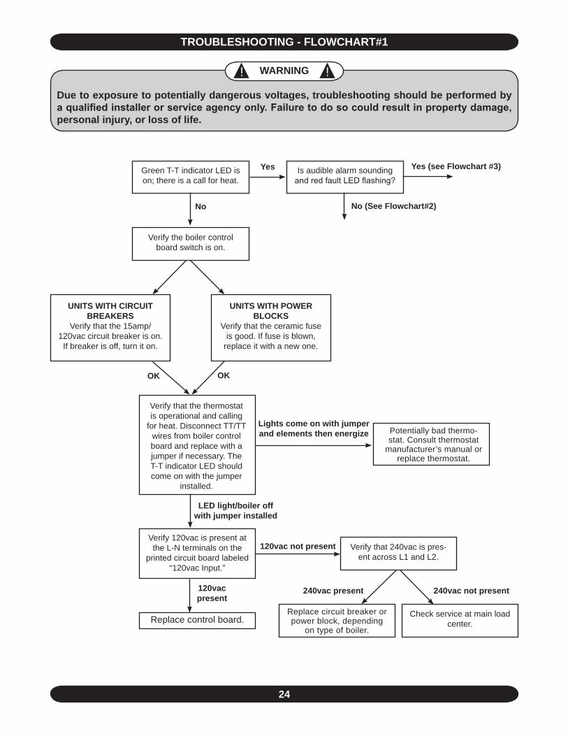
TROUBLESHOOTING - FLOWCHART#1
Green T-T indicator LED is on; there is a call for heat.
Verify the boiler control board switch is on.
Verify 120vac is present at the L-N terminals on the
printed circuit board labeled “120vac Input.”
Replace control board.
No
UNITS WITH POWER BLOCKS
Verify that the ceramic fuse is good. If fuse is blown,
replace it with a new one.
UNITS WITH CIRCUIT BREAKERS
Verify that the 15amp/120vac circuit breaker is on.
If breaker is off, turn it on.
Verify that the thermostat is operational and calling
for heat. Disconnect TT/TT wires from boiler control board and replace with a jumper if necessary. TheT-T indicator LED should come on with the jumper
installed.
OK OK
Lights come on with jumper and elements then energize
Replace circuit breaker or power block, depending
on type of boiler.
Check service at main load center.
Verify that 240vac is pres-ent across L1 and L2.
LED light/boiler off with jumper installed
120vac not present
120vac present
240vac not present240vac present
Yes Is audible alarm sounding and red fault LED flashing?
Yes (see Flowchart #3)
No (See Flowchart#2)
! ! WARNING
Due to exposure to potentially dangerous voltages, troubleshooting should be performed by a qualified installer or service agency only. Failure to do so could result in property damage, personal injury, or loss of life.
Potentially bad thermo-stat. Consult thermostat
manufacturer’s manual or replace thermostat.
25
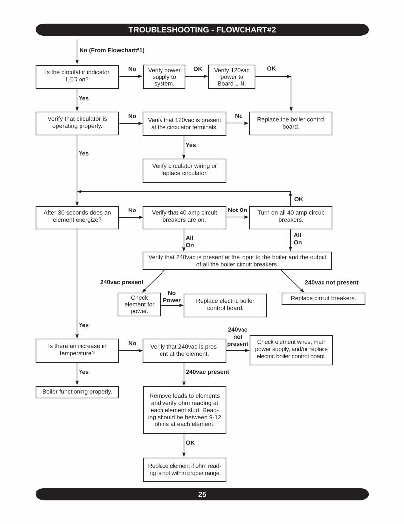
Verify power supply to system.
TROUBLESHOOTING - FLOWCHART#2
Is the circulator indicator LED on?
No (From Flowchart#1)
Yes
No Verify that circulator is operating properly.
Verify that 120vac is present at the circulator terminals.
No Replace the boiler control board.
Yes
Verify circulator wiring or replace circulator.
Yes
No After 30 seconds does an element energize?
Not On Turn on all 40 amp circuit breakers.
Verify that 40 amp circuit breakers are on.
All On
Verify that 240vac is present at the input to the boiler and the output of all the boiler circuit breakers.
240vac not present240vac present
Replace circuit breakers.
Yes
No Is there an increase in temperature?
240vac not
present Verify that 240vac is pres-ent at the element.
Check element wires, main power supply, and/or replace electric boiler control board.
Yes
Boiler functioning properly.Remove leads to elements and verify ohm reading at each element stud. Read-
ing should be between 9-12 ohms at each element.
OK
240vac present
Replace element if ohm read-ing is not within proper range.
No OK Verify 120vac power to
Board L-N.
OK
OK
All On
No Power Replace electric boiler
control board.
Check element for
power.

26
TROUBLESHOOTING - FLOWCHART#3
Is v
isua
l/aud
ible
ala
rm
flash
ing/
puls
ing
once
?
Is a
low
wat
er c
ut-o
ff in
stal
led?
Saf
ety
Sw
itch
Faul
t.
Rem
ove
lead
s fro
m H
L-H
L te
rmin
als
on c
ontro
l boa
rd
and
test
with
a ju
mpe
r.
Doe
s vi
sual
/aud
ible
ala
rm
shut
off
with
jum
per i
n-st
alle
d?
Is v
isua
l/aud
ible
ala
rm
flash
ing/
puls
ing
thre
e tim
es?
Is v
isua
l/aud
ible
ala
rm
flash
ing/
puls
ing
four
tim
es?
Is v
isua
l/aud
ible
ala
rm
flash
ing/
puls
ing
twic
e?
Stu
ck/w
elde
d el
emen
t rel
ay
cont
act.
Rep
lace
ele
ctric
bo
iler c
ontro
l boa
rd.
RTD
sho
rt. F
ollo
w s
teps
on
page
10
to c
heck
RTD
and
re
plac
e if
nece
ssar
y.
RTD
ope
n. F
ollo
w s
teps
on
page
10
to c
heck
RTD
and
re
plac
e if
nece
ssar
y.
Yes
Yes
Yes
Yes
No
No
No
Rem
ove
jum
per f
rom
HL-
HL
term
inal
s an
d re
-pl
ace
lead
s.
No
OK
OK
Yes
OK O
K (S
ee
Flow
char
t#4)
Rem
ove
lead
s fro
mLW
C-L
WC
and
test
with
a
jum
per.
Rep
lace
hig
h lim
it co
ntro
l sw
itche
s.Is
a fl
ow s
witc
h in
stal
led?
No
No
Yes
Yes
(Fro
m
Flow
-ch
art#
1)
Yes
AB
C

27
TROUBLESHOOTING - FLOWCHART#4
"AT" SERIES BOILER DIMENSIONS
A
B
CD
E
Remove jumper fromLWC-LWC and replace
LWC-LWC leads.
OK
Check water supply and water level in system. Fill system if low. Does visual/audible alarm shut off with
system full? OK
OK (From Flowchart#3)
Yes
A
No
B
Remove jumper fromflow-flow and replace leads.
No
OK
C
Potentially bad flow switch. Check wiring to flow switch
and consult flow switch manufacturer if necessary.
Yes
Potentially bad low water cut-off. Check wiring to
LWCO and consult LWCO manufacturer if necessary.
NoCheck pump and flow
rate of system. Pump may require replacement. Does
visual/audible alarm shut off with a new pump?
No
Yes
Yes
Dimensions Inlet & Outlet Pipe Size
Approximate Shipping Wt.A B C D E
14-5/8” 18-5/8 “ 9-1/32” 14-3/8” 16-15/32” 1-1/4” NPT 70 lbs.
Does visual/audible alarm shut off with jumper in-
stalled?
Does visual/audible alarm shut off with jumper installed?
Remove leads fromflow-flow and test with a
jumper.

HOMEOWNER'S REFERENCE TABLE
Model Number: _____________________________________________
Serial Number: ______________________________________________
Date Installed: ______________________________________________
Contractor: _________________________________________________
Contact: ___________________________________________________
Address: ___________________________________________________
___________________________________________________________
Telephone Number: __________________________________________
After Hours Number: _________________________________________
If different from Installation Contractor:
Service Tech: _______________________________________________
Telephone Number: __________________________________________
After Hours Number: _________________________________________
www.argocontrols.com