d/ ^ ^ n85-16936 - nasa control and data subsystem controls the entire system, and provides operator...
TRANSCRIPT
N85-16936D/ ^ ^
HISTORY, DESIGN AND PERFORMANCE OF THESPACE SHUTTLE HAZARDOUS GAS DETECTION SYSTEM
William R. HelmsNASA, Engineering Development Directorate
John F. Kennedy Space Center, Florida 32899
ABSTRACT
Large quantities of hazardous cryogenic propellants are loaded aboard the Space Shuttle priorto launch. The Hazardous Gas Detection System is designed to detect leaks which could resultin pre-launch or in-flight fires or explosions.
This paper describes the historical development, design, ani performance of the HGDS. Data forresponse time, detection limits, accuracy, and drift are presented. Finally, present and future ap-plications are discussed, and some general conclusions are drawn.
INTRODUCTION
Over 1.5 million pounds of liquid oxygen and liquid hydrogen are pumped onto the Space Shuttle
during final countdown. Leaks, either during pre-flight preparations, or in-flight could result ina fire or explosion which would endanger the Space Shuttle and its crew. The Hazardous Gas DetectionSystem (HGDS) is designed to detect the presence and measure the concentration of hazardous gases
within the Space Shuttle.
The HGDS is located inside the Mobile Launch Platform and consists of three subsystems. The sam-
ple delivery subsystem draws samples from four Space Shuttle compartments surrounding propellant tanksand engines, and provides calibration gas samples. These compartments are the External Tank Intertank
Area, the Orbiter Aft Fuselage, Payload Bay, and Midbody. All are purged with gaseous nitrogen during
propellant loading. The mass spectrometer measures the samples from these areas qualitatively andquantitively for specific compounds. These are hydrogen, oxygen, helium, argon, and up to four others.The control and data subsystem controls the entire system, and provides operator interface for local
setup via keypads and a display panel. Once this setup is complete, control is transferred to the Fir-ing Room in the Launch Control Center. All measurement and control during propellant loading ishandled through the Launch Processing System. The Firing Room console operator controls the system
and warns propellant loading and test management personnel of leaks which might endanger the Shuttleor the astronauts.
HTSTORY
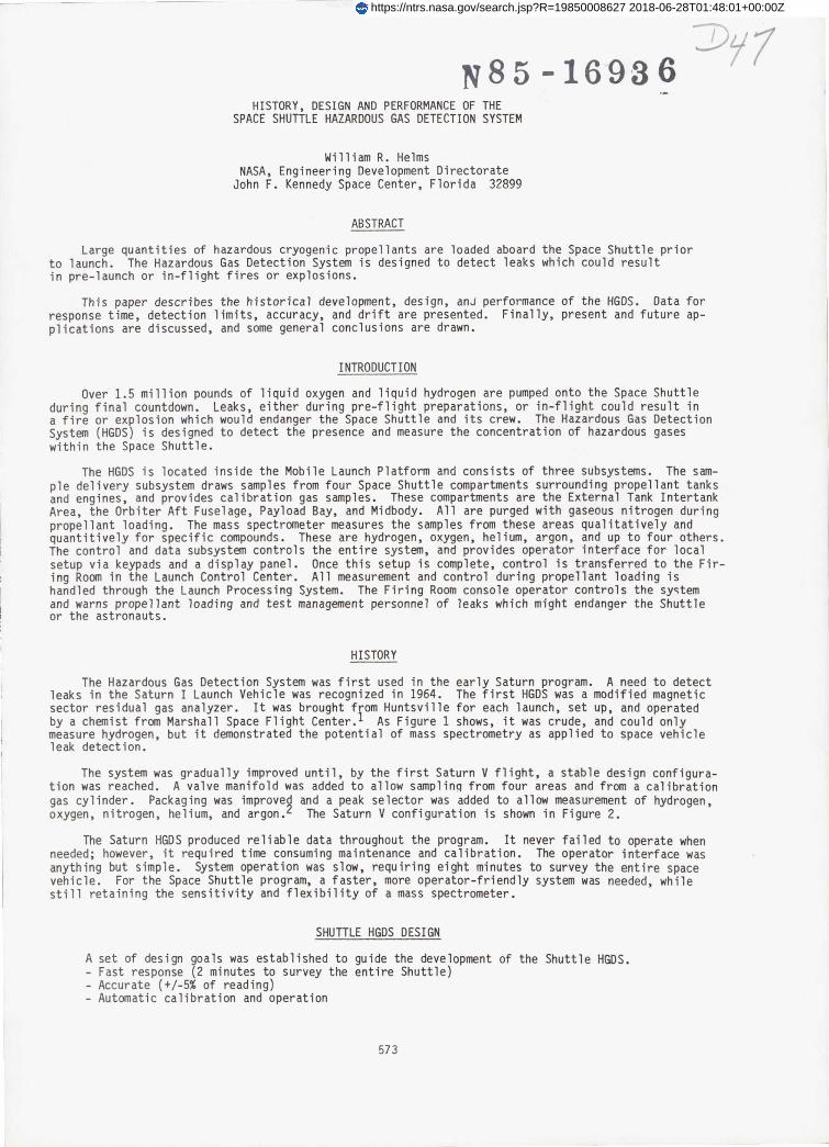
The Hazardous Gas Detection System was first used in the early Saturn program. A need to detectleaks in the Saturn I Launch Vehicle was recognized in 1964. The first HGDS was a modified magneticsector residual gas analyzer. It was brought from Huntsville for each launch, set up, and operated
by a chemist from Marshall Space Flight Center. 1 As Figure 1 shows, it was crude, and could onlymeasure hydrogen, but it demonstrated the potential of mass spectrometry as applied to space vehicleleak detection.
The system was gradually improved until, by the first Saturn V flight, a stable design configura-tion was reached. A valve manifold was added to allow samplinq from four areas and from a calibration
gas cylinder. Packaging was improved and a peak selector was added to allow measurement of hydrogen,
oxygen, nitrogen, helium, and argon. 2 The Saturn V configuration is shown in Figure 2.
The Saturn HGDS produced reliable data throughout the program. It never failed to operate whenneeded; however, it required time consuming maintenance and calibration. The operator interface was
anything but simple. System operation was slow, requiring eight minutes to survey the entire spacevehicle. For the Space Shuttle program, a faster, more operator-friendly system was needed, whilestill retaining the sensitivity and flexibility of a mass spectrometer.
SHUTTLE HGDS DESIGN
A set of design goals was established to guide the development of the Shuttle HGDS.- Fast response (2 minutes to survey the entire Shuttle)- Accurate (+/-5% of reading)- Automatic calibration and operation
573
https://ntrs.nasa.gov/search.jsp?R=19850008627 2018-06-28T01:48:01+00:00Z
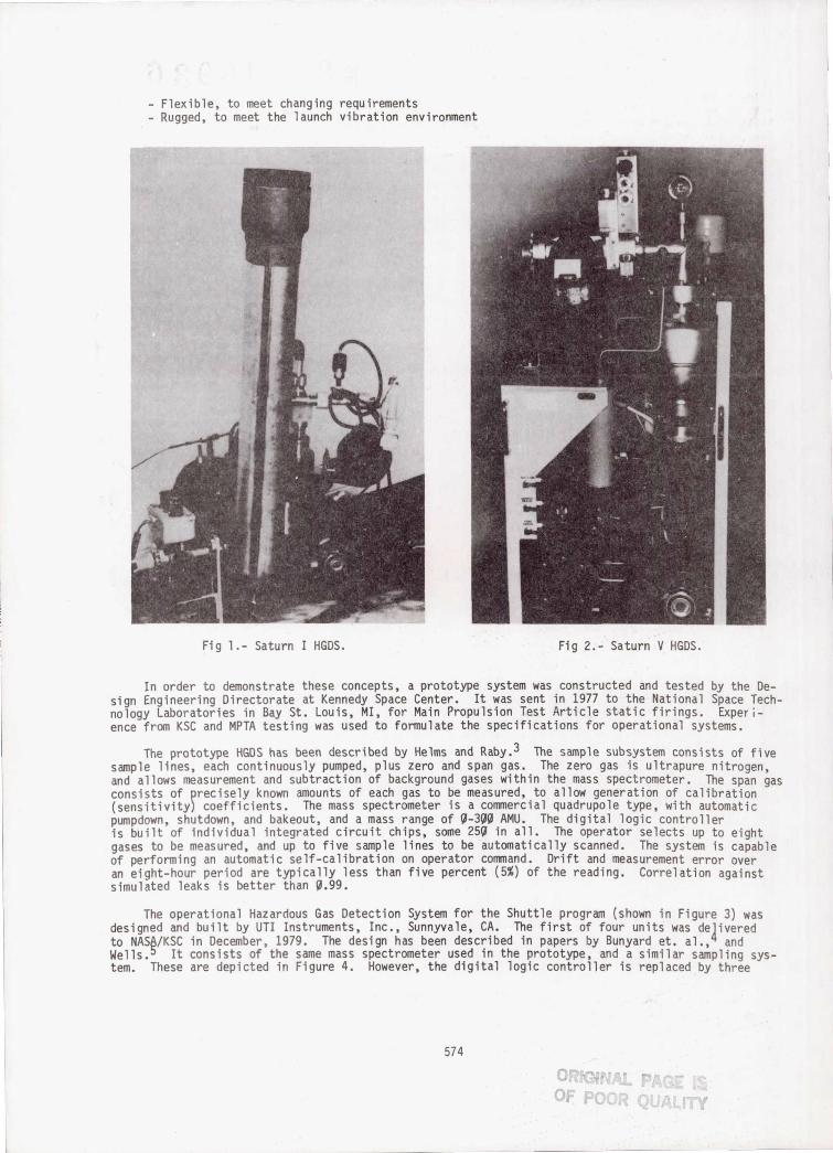
Fig l.- Saturn I HGDS. Fig 2.- Saturn V HGDS.
Flexible, to meet changing requirementsRugged, to meet the launch vibration environment
In order to demonstrate these concepts, a prototype system was constructed and tested by the De-sign Engineering Directorate at Kennedy Space Center. It was sent in 1977 to the National Space Tech-nology Laboratories in Bay St. Louis, MI, for Main Propulsion Test Article static firings. Exper -ence from KSC and MPTA testing was used to formulate the specifications for operational systems.
The prototype HGDS has been described by Helms and Raby. 3 The sample subsystem consists of five
sample lines, each continuously pumped, plus zero and span gas. The zero gas is ultrapure nitrogen,and allows measurement and subtraction of background gases within the mass spectrometer. The span gas
consists of precisely known amounts of each gas to be measured, to allow generation of calibration(sensitivity) coefficients. The mass spectrometer is a commercial quadrupole type, with automatic
pumpdown, shutdown, and bakeout, and a mass range of 9-399 AMU. The digital logic controlleris built of individual integrated circuit chips, some 259 in all. The operator selects up to eight
gases to be measured, and up to five sample lines to be automatically scanned. The system is capableof performing an automatic self-calibration on operator command. Drift and measurement error overan eight-hour period are typically less than five percent (5%) of the reading. Correlation againstsimulated leaks is better than 9.99.
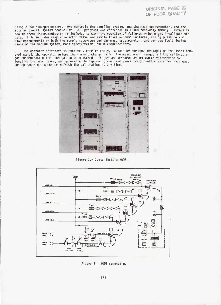
The operational Hazardous Gas Detection System for the Shuttle program (shown in Figure 3) wasdesigned and built by UTI Instruments, Inc., Sunnyvale, CA. The first of four units was de]ivered
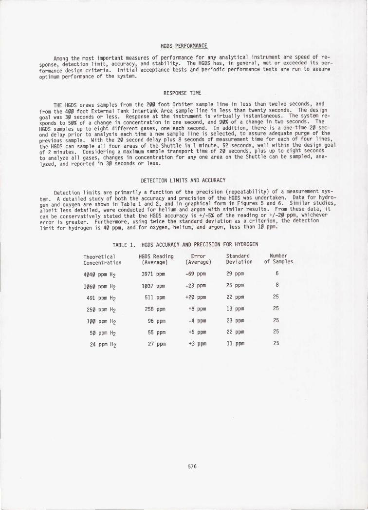
to NAS^/KSC in December, 1979. The design has been described in papers by Bunyard et, a1., 44 andWells. It consists of the same mass spectrometer used in the prototype, and a similar sampling sys-tem. These are depicted in Figure 4. However, the digital logic controller is replaced by three
574
0111PAGE m^
OF PC QUALITY
ORIGINAL PAGE 19OF POOR QUALITY
Zilog Z-8QA Microprocessors. One controls the sampling system, one the mass spectrometer, and oneacts as overall system controller. All programs are contained in EPROM read-only memory. Extensivehealth-check instrumentation is included to warn the operator of failures which might invalidate thedata. This includes sample selector valve and sample transfer pump failures, analog pressure andflow measurements on both the sample subsystem and the mass spectrometer, and various fault indica-tions on the vacuum system, mass spectrometer, and microprocessors.
The operator interface is extremely user-friendly. Guided by "prompt" messages on the local con-trol panel, the operator enters the mass-to-charge ratio, the measurement range, and the calibrationgas concentration for each gas to be measured. The system performs an automatic calibration bylocating the mass peaks, and generating background (zero) and sensitivity coefficients for each gas.The operator can check or refresh the calibration at any time.
1
ED
rl
:FF
Figure 3.- Space Shuttle HGDS.
Figure 4.- HGDS schematic.
575
HGDS PERFORMANCE
Among the most important measures of performance for any analytical instrument are speed of re-sponse, detection limit, accuracy, and stability. The HGDS has, in general, met or exceeded its per-formance design criteria. Initial acceptance tests and periodic performance tests are run to assureoptimum performance of the system.
RESPONSE TIME .
THE HGDS draws samples from the 200 foot Orbiter sample line in less than twelve seconds, andfrom the 400 foot External Tank Intertank Area sample line in less than twenty seconds. The designgoal was 30 seconds or less. Response at the instrument is virtually instantaneous. The system re-sponds to 50% of a change in concentration in one second, and 90% of a change in two seconds. TheHGDS samples up to eight different gases, one each second. In addition, there is a one-time 20 sec-ond delay prior to analysis each time a new sample line is selected, to assure adequate purge of theprevious sample. With the 20 second delay plus 8 seconds of measurement time for each of four lines,the HGDS can sample all four areas of the Shuttle in 1 minute, 52 seconds, well within the design goalof 2 minutes. Considering a maximum sample transport time of 20 seconds, plus up to eight secondsto analyze all gases, changes in concentration for any one area on the Shuttle can be sampled, ana-lyzed, and reported in 30 seconds or less.
DETECTION LIMITS AND ACCURACY
Detection limits are primarily a function of the precision (repeatability) of a measurement sys-tem. A detailed study of both the accuracy and precision of the HGDS was undertaken. Data for hydro-gen and oxygen are shown in Table 1 and 2, and in graphical form in Figures 5 and 6. Similar studies,albeit less detailed, were conducted for helium and argon with similar results. From these data, itcan be conservatively stated that the HGDS accuracy is +/-5% of the reading or +1-20 ppm, whichevererror is greater. Furthermore, using twice the standard deviation as a criterion, the detectionlimit for hydrogen is 40 ppm, and for oxygen, helium, and argon, less than 10 ppm.
TABLE 1. HGDS ACCURACY AND PRECISION FOR HYDROGEN
Theoretical HGDS Reading Error Standard Number
Concentration (Average) (Average) Deviation of Samples
4040 ppm H2 3971 ppm -69 ppm 29 ppm 6
1060 ppm H2 1037 ppm -23 ppm 25 ppm 8
491 ppm H2 511 ppm +20 ppm 22 ppm 25
250 ppm H2 258 ppm +8 ppm 13 ppm 25
100 ppm H2 96 ppm -4 ppm 23 ppm 25
50 ppm H2 55 ppm +5 ppm 22 ppm 25
24 ppm H2 27 ppm +3 ppm 11 ppm 25
I
576
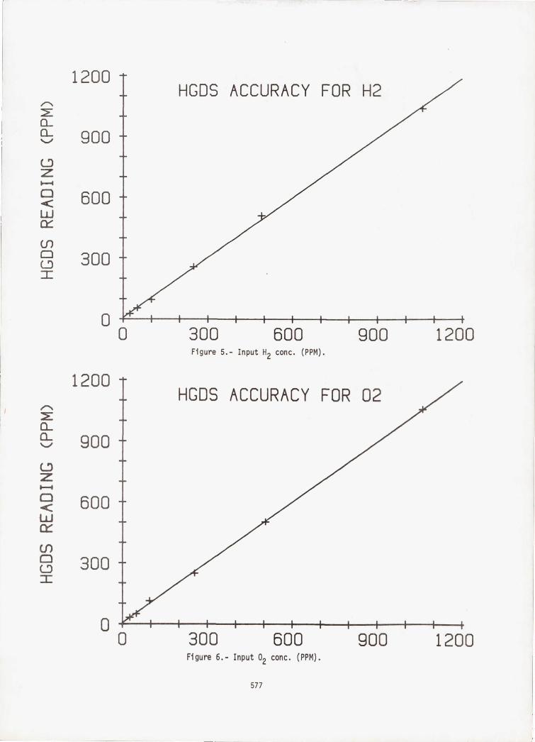
0 300 600 900 1200Figure 5.- Input H Z conc. (PPM).
0 300 600 900 1200Figure 6.- Input 0 2 conc. (PPM).
1200
n°- 900coz0 600wcn0 300
0
1200
a_a_ 900
z0 600wcn0 300
0
577
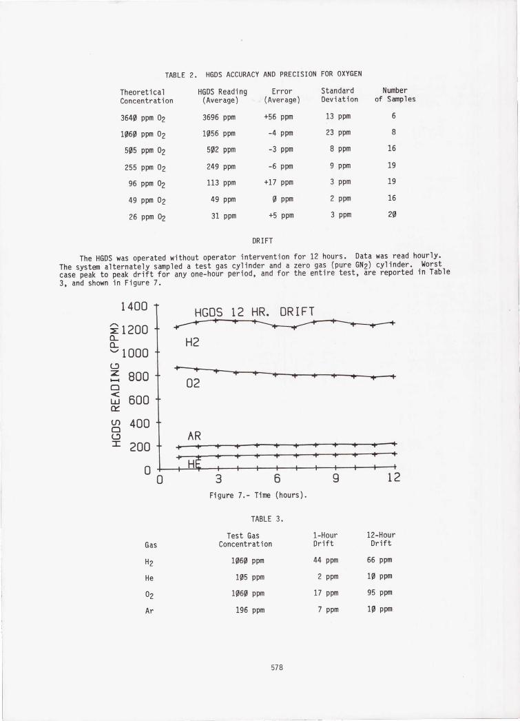
TABLE 2. HGDS ACCURACY AND PRECISION FOR OXYGEN
Theoretical HGDS Reading Error Standard Number
Concentration (Average) (Average) Deviation of Samples
3640 ppm 02 3696 ppm +56 ppm 13 ppm 6
1060 ppm 02 1056 ppm -4 ppm 23 ppm 8
505 ppm 02 502 ppm -3 ppm 8 ppm 16
255 ppm 02 249 ppm -6 ppm 9 ppm 19
96 ppm 02 113 ppm +17 ppm 3 ppm 19
49 ppm 02 49 ppm 0 ppm 2 ppm 16
26 ppm 02 31 ppm +5 ppm 3 ppm 20
DRIFT
The HGDS was operated without operator intervention for 12 hours. Data was read hourly.The system alternately sampled a test gas cylinder and a zero gas (pure GN2) cylinder. Worstcase peak to peak drift for any one-hour period, and for the entire test, are reported in Table3, and shown in Figure 7.
1400 HGDS 12 HR. DRIFT
12000- H2
1000C-0 t---+
800020
w 600ry
0 400LD AR= 200
0 0 3 6 9 12
Figure 7.- Time (hours).
TABLE 3.
Test Gas 1-Hour 12-Hour
Gas Concentration Drift Drift
H 2 1060 ppm 44 ppm 66 ppm
He 105 ppm 2 ppm 10 ppm
0 2 1060 ppm 17 ppm 95 ppm
Ar 196 ppm 7 ppm 10 ppm
578
5000
5000vz 40000
3000ry
w 2000UZ
U 1000
0-20 0 20 40 60 80 100
DESIGN IMPROVEMENTS
Like many computer-based systems, the HGDS has suffered from AC power line noise. Due to exces-sive noise on the Mobile Launcher Uninterruptible Power System (UPS), the HGDS was placed on a dedi-cated mini-UPS, which solved the power related problems.
The HGDS uses an ion pump to achieve the requisite vacuum of one-billionth of an atmosphere.This type of pump is susceptible to eventual hydrogen saturation and subsequent spontaneous, periodic
elution, called "burping". This causes a degradation of measurement precision. The only solution isreplacement of the ion pump. A recent modification has made this a simple, risk-free, one-hour proce-dure.
Several minor microprocessor firmware "bugs" have been identified and corrections are inwork. Component faiures have been within acceptable limits.
APPI TCATTDNS
The HGDS is used to make critical go - no go decisions during the Space Shuttle countdown. TheLaunch Commit Criteria Document specifies the maximum allowable limits. A concentration of 800
parts per million of hydrogen or oxygen is considered unacceptable for flight. Leakage of this magni-tude at preflight propellant pressures could indicate a leak which would create flammable conditions
when the propellants are at the much higher flight pressures. A concentration of 10,000 partsper million of hydrogen or oxygen (25% of the lower flammable limit) is considered an immediate on-pad hazard.
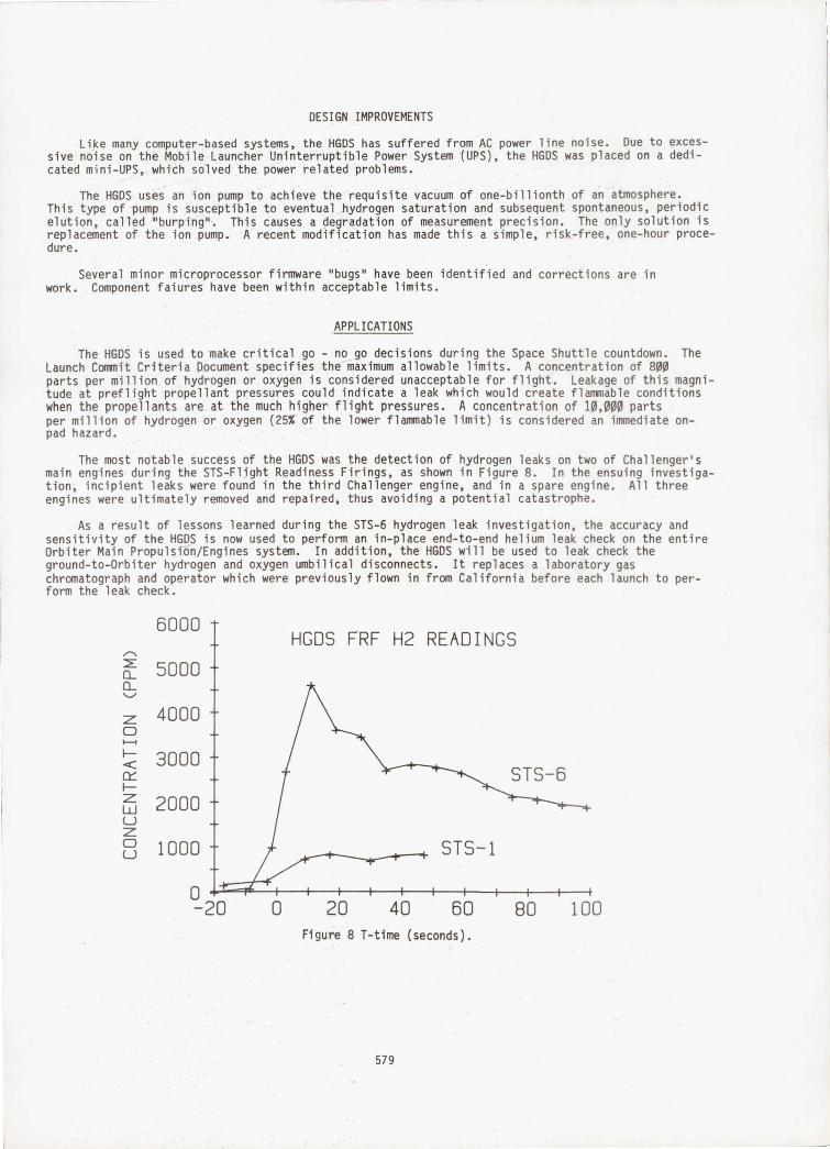
The most notable success of the HGDS was the detection of hydrogen leaks on two of Challenger'smain engines during the STS-Flight Readiness Firings, as shown in Figure 8. In the ensuing investiga-tion, incipient leaks were found in the third Challenger engine, and in a spare engine. All threeengines were ultimately removed and repaired, thus avoiding a potential catastrophe.
As a result of lessons learned during the STS-6 hydrogen leak investigation, the accuracy and
sensitivity of the HGDS is now used to perform an in-place end-to-end helium leak check on the entireOrbiter Main Propulsion/Engines system. In addition, the HGDS will be used to leak check theground-to-Orbiter hydrogen and oxygen umbilical disconnects. It replaces a laboratory gas
chromatograph and operator which were previously flown in from California before each launch to per-form the leak check.
Figure 8 T-time (seconds).
579
rnNri iicrnNs
The HGDS is an accurate, stable, and sensitive analytical instrument. It can make reliable meas-
urements of a variety of gases at a few parts per million. Launch vibration has caused only one minorfailure in six launches. Calibration can be verified and refreshed in real time, thus allowing high
confidence to be placed in the data. It has demonstrated its importance to the Space Shuttle programby detecting leaks which, if uncorrected, could have caused a catastrophe. With the advent of cryo-genic payloads such as Centaur within the Space Shuttle Payload Bay, that importance can only in-crease.
RFFFRFNrPc
1. Perry, C. L., Personal Communication
2. Perry, C. L., Krupnick, A. C., and Harwell, R. J.: Design and Development of the HazardousGas Detection System for Launch Vehicle Propellant Loading and Checkout. NASA TM X-53720,1968.
3. Helms, William R. and Raby, Bruce A., "a Prototype Hazardous Gas Detection System for NASA's
Space Shuttle", 26th Annual Conference of American Society for Mass Spectrometry, St. Louis,MO, May, 1978.
4. Bunyard, G. B., Wells, P., Jewhurst, F., and Raby, B. A., "Hazardous Gas Detection Systemfor Space Shuttle", Instrument Society of America National Conference, Chicago, IL, 1979.
REFERENCES (CONT)
5. Wells, P., "A Microprocessor-Controlled Hazardous Gas Monitor", UTI Journal, Vol, 3, No. 2,
1980.
580