d j a inspection services, inc. - … · d j a inspection services, inc. storage tank management...
TRANSCRIPT

D J A INSPECTION SERVICES, INC. Storage Tank Management & Inspection
814-676-3663 P. O. Box 384 Reno, PA 16343 661-363-5453 P. O. Box 544 Edison, CA 93220
PORT OIL PORTLAND, CT
Tank #1
Date of Out - of - Service Inspection: September 2, 2010
Inspector: COLLIN GORDON API Certificate #34922 STI Certificate #AC 19910 Copies: Port Oil – 3 File - 1
Dependable • Judicious • Affordable

DJA Inspection Service, Inc. Purpose
This report is given to enable one to assess the serviceability of this tank. The report is of an API-653 inspection made by DJA InspectionServices, Inc. It is the mission of DJA Inspection Services to provide full service tank inspections to the storage tank industry, to be known for quality and detailed inspections through the dedication and experience of our team and to provide the service worldwide as well as to the individual tank owner. DJA obtains this through the use of proper instrumentation, equipment, and trained inspectors. DJA also insists on its minimum inspection requirements being fulfilled even if they exceed the customer’s request. With DJA, the report content and context is weighted heavily in all inspections. DJA intends to provide this service at a reasonable rate and provide reports in a timely manner.

SUMMARY/RECOMMENDATIONS
Recommendations found in this report made by DJA Inspection Services, Inc. are for report purposes only. Actual repair needs are to be determined and designed by the tank owner after review of the entire report.
MISSION STATEMENT “It is the mission of DJA Inspection Services, Inc. to provide full service tank inspections to the storage tank industry, to be known for quality and detailed inspections through the dedication and experience of our team and to provide the service worldwide as well as to the individual tank owner.”

PORT OILPORTLAND, CT
TANK #1
Out-of-Service Inspection of 09/02/2010
Summary:
CONTAINMENT AREA - The visual inspection of the concrete walls found minor cracks. The cracks need to be sealed to stop product in the event of a tank failure. The base is mostlysoil with stone and asphalt covering the soil. The containment area has poor drainage awayfrom the tank. The containment base should be lowered to improve the drainage.
FOUNDATION - The tank is on a soil foundation. The foundation has no berm. The tank isapproximately 4" below the surrounding grade.
LEAK DETECTION - None.
SECONDARY CONTAINMENT - None.
SETTLEMENT SURVEYS - An out-of-plane settlement survey and an edge settlementsurvey were performed on the tank. The out-of-plane settlement is acceptable per API-653. The edge settlement exceeded the initial guidelines per API-653 at 9 of the locationssurveyed. The 9 locations were checked by magnetic particle testing, with no cracks found. Further evaluation needs to be performed on these areas.
FIXED ROOF - The steel cone roof was visually inspected and thickness readings were taken. No serious conditions were found.
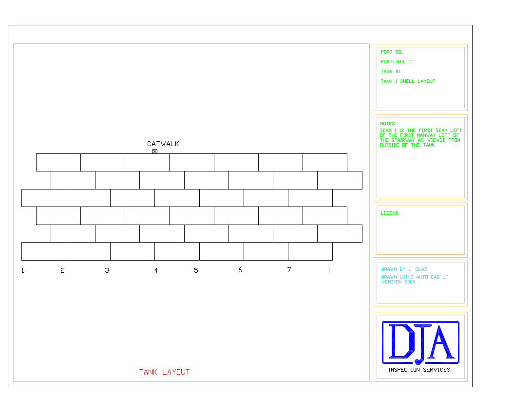
SHELL - The visual inspection found an external belly band patch has been installed aroundthe bottom 1' of the shell. The belly band does not meet API guidelines for length or weldspacing requirements. The ultrasound thickness readings found minor corrosion losses on thebottom 6" of shell course one. The corrosion is covered by the belly band. The shell has lappatches that do not meet API weld spacing requirements. Due to corrosion rate and remainingcorrosion allowance of the first shell course, the maximum facility fill height (33' 9") shouldbe lowered to 32.9', which facilitates enough remaining corrosion allowance for a 5.0 yearnext in-service inspection interval per API-653 (this calculation is for the current product, #2fuel oil, specific gravity = .910). At a gravity of 1.0 (water), the facility fill height would needto be lowered to 29.95' for a 5.0 year next in-service inspection interval per API-653.
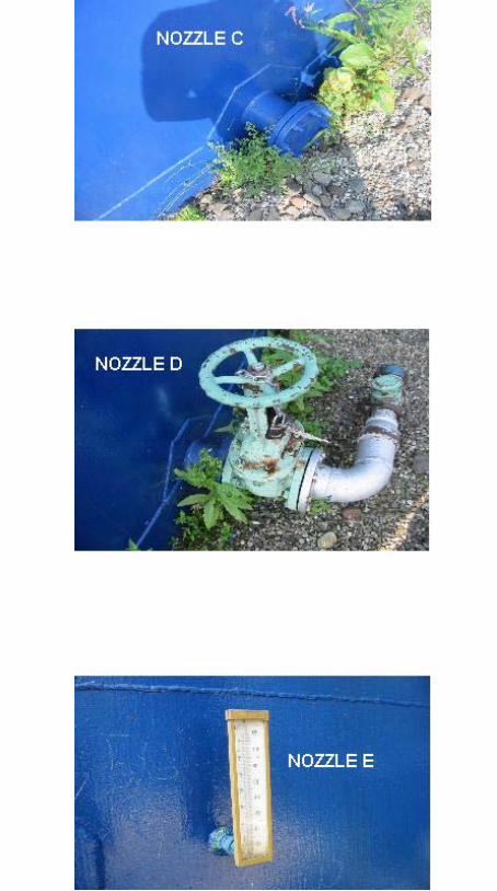
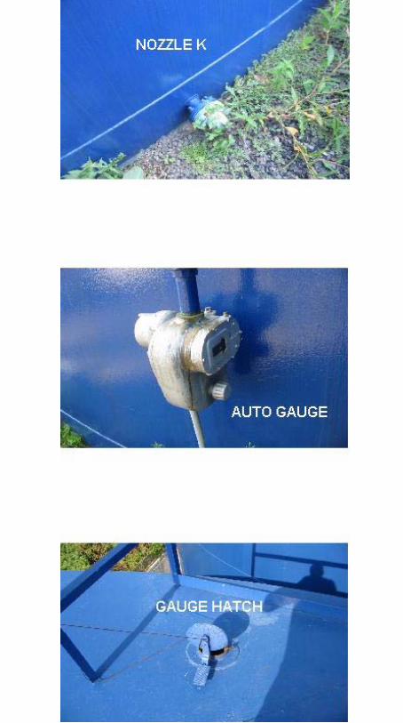
NOZZLES - The nozzles were visually inspected and thickness readings were taken. Thevisual inspection found the nozzle reinforcement pads do not have tell-tale holes installed. The ultrasound thickness readings found no serious conditions.
CHIME - The chime is partially covered by the belly band patch on the shell. The chime hasno signs of significant corrosion, so the chime does not require repair at this time. The ownershould be aware that, if the chime was corroded beyond the belly band weld, repair would be
required.
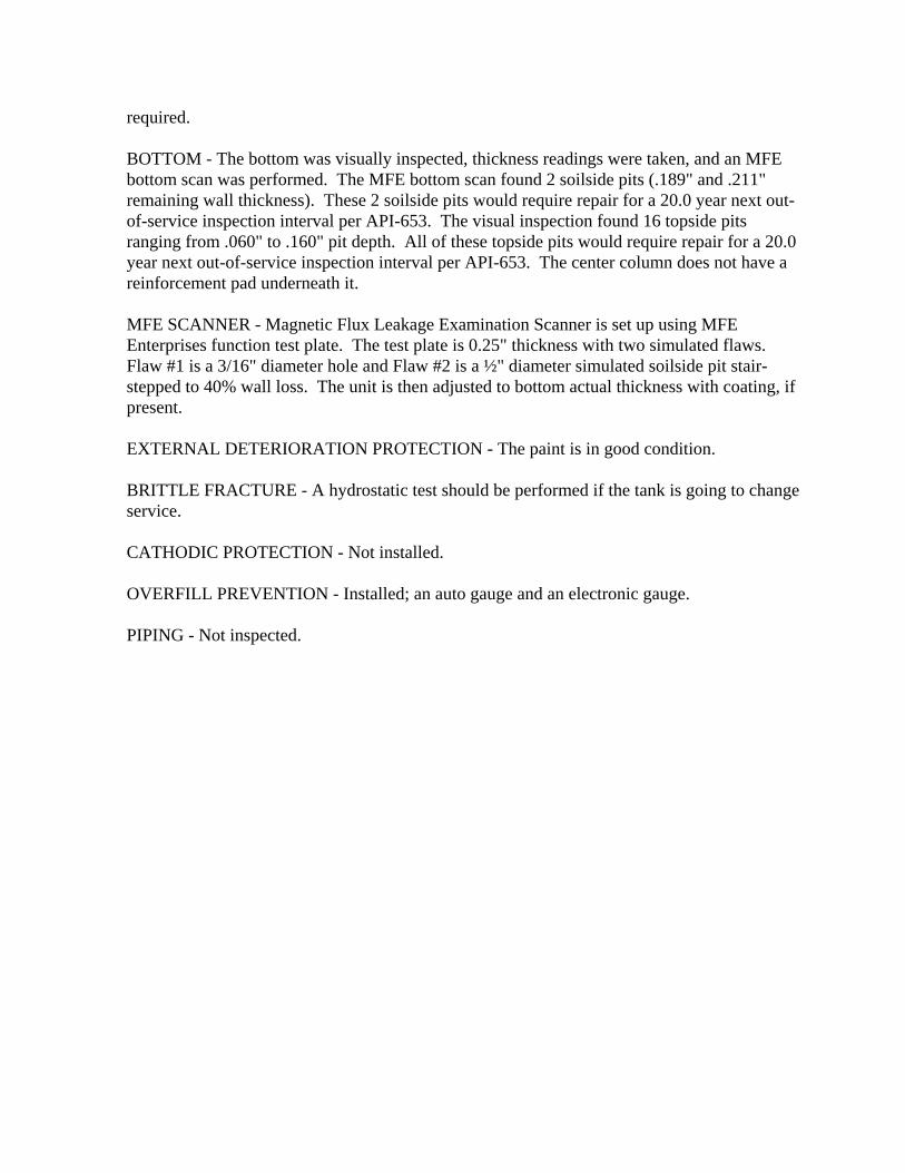
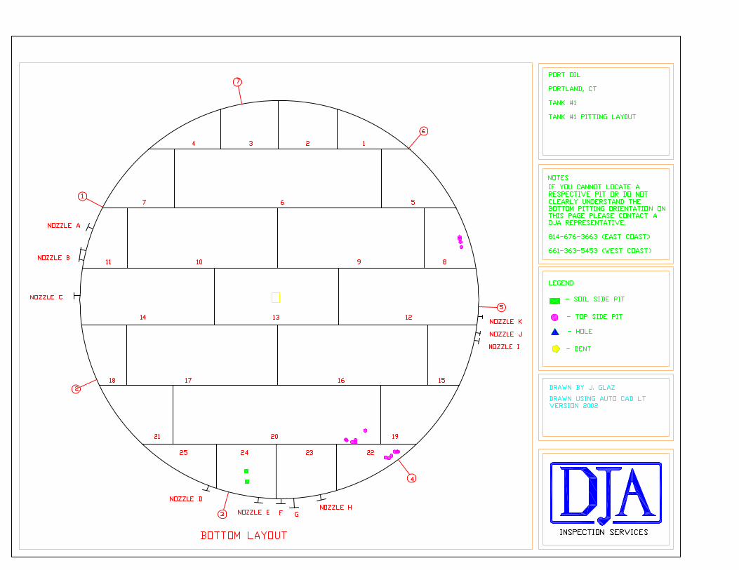
BOTTOM - The bottom was visually inspected, thickness readings were taken, and an MFEbottom scan was performed. The MFE bottom scan found 2 soilside pits (.189" and .211"remaining wall thickness). These 2 soilside pits would require repair for a 20.0 year next out-of-service inspection interval per API-653. The visual inspection found 16 topside pitsranging from .060" to .160" pit depth. All of these topside pits would require repair for a 20.0year next out-of-service inspection interval per API-653. The center column does not have areinforcement pad underneath it.
MFE SCANNER - Magnetic Flux Leakage Examination Scanner is set up using MFEEnterprises function test plate. The test plate is 0.25" thickness with two simulated flaws. Flaw #1 is a 3/16" diameter hole and Flaw #2 is a ½" diameter simulated soilside pit stair-stepped to 40% wall loss. The unit is then adjusted to bottom actual thickness with coating, ifpresent.
EXTERNAL DETERIORATION PROTECTION - The paint is in good condition.
BRITTLE FRACTURE - A hydrostatic test should be performed if the tank is going to changeservice.
CATHODIC PROTECTION - Not installed.
OVERFILL PREVENTION - Installed; an auto gauge and an electronic gauge.
PIPING - Not inspected.
PORT OILPORTLAND, CT
TANK #1
Out-of-Service Inspection of 09/02/2010
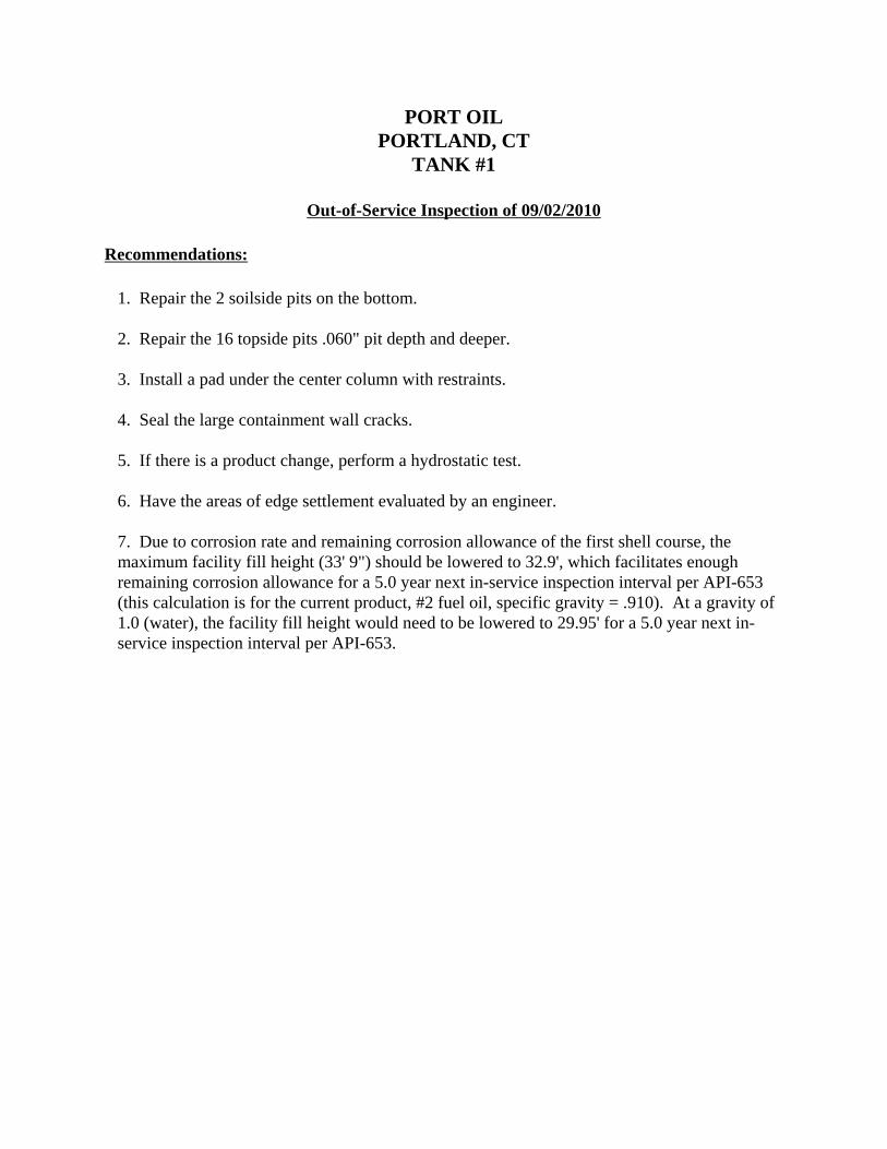
Recommendations:
1. Repair the 2 soilside pits on the bottom.
2. Repair the 16 topside pits .060" pit depth and deeper.
3. Install a pad under the center column with restraints.
4. Seal the large containment wall cracks.
5. If there is a product change, perform a hydrostatic test.
6. Have the areas of edge settlement evaluated by an engineer.
7. Due to corrosion rate and remaining corrosion allowance of the first shell course, themaximum facility fill height (33' 9") should be lowered to 32.9', which facilitates enoughremaining corrosion allowance for a 5.0 year next in-service inspection interval per API-653(this calculation is for the current product, #2 fuel oil, specific gravity = .910). At a gravity of1.0 (water), the facility fill height would need to be lowered to 29.95' for a 5.0 year next in-service inspection interval per API-653.

PORT OILPORTLAND, CT
TANK #1
Out-of-Service Inspection of 09/02/2010
Suggestions:
1. Lower the containment base and improve drainage away from the tank.
2. Install tell-tale holes in the nozzle reinforcement pads and pressure test per API-650.
3. Install a foundation berm after the containment base is lowered.

Procedures
THICKNESS TESTING - Thickness readings were obtained by the use of an ultrasonicthickness tester. The calibration was checked before starting each day of inspection.
LEVEL AND SETTLEMENT SURVEY - The settlement and / or levelness of the tankfoundation was determined with the use of transit level and measuring rod.
ROOF LAYOUT - Roof plates were measured with a measuring wheel and reports are to scale. The roof was visually inspected and thickness readings were taken.
BOTTOM LAYOUT - Bottom plates were measured with a measuring wheel and reports areto scale. The bottom was visually inspected and thickness readings were taken.
NOZZLE LAYOUT - Nozzles were measured as to an X,Y, coordinate in relationship to theshell plate in which they are located. The nozzles size is listed as well as identified by a letter. The nozzles were inspected visually from the internal side of the tank and thicknessmeasurements were obtained by the use of an ultrasonic thickness tester.
PIT MEASUREMENT - Pit depth was measured with the use of a pit gauge.
VISUAL - A visual inspection was made of the tank and its components. Internal inspectionwas aided by the use of a flashlight being held parallel to the tank’s surface.
MAGNETIC FLUX LEAKAGE - The floor was scanned for topside and soilside pitting usinga magnetic flux leakage tester.

SPREADSHEETS
MISSION STATEMENT “It is the mission of DJA Inspection Services, Inc. to provide full service tank inspections to the storage tank industry, to be known for quality and detailed inspections through the dedication and experience of our team and to provide the service worldwide as well as to the individual tank owner.”

Tank Data Summary
Customer : PORT OIL Location : PORTLAND, CTTank # : 1 Serial # : UNAVAILABLEManufacturer : UNKNOWN Year Built : 1954Tank Description : BUTT WELDED Diameter : 49.00 feetProduct : #2 FUEL OIL Height : 35.90 feetCode : UNKNOWN Design Capacity : 506,400 galProduct Specific Grav. : 0.910 12100 bbl
Maximum Filling Height Used by Facility : 32.90 feetCalculated Filling Height Using S.G.: 33.62 feet
Is vessel on original location? : YVessel drawings? : N Normal Venting Evaluation:Is vessel modified? : UNAVAILABLEAny previous inspection records? : N Venting, Sq in :Any maintenance records? : N Fill openings, Sq in :Any weld examination records? : N Outlets, Sq in :Any leak test records? : NAny mill test records? : N
Pressure, operating/design (psig) : ATMOS./ATMOS.Temperature, operating/design (°F) : AMBIENT/AMBIENT
Shell Material Spec : UNKNOWN
Roof type : STEEL CONEFloating roof? : NIf so, description : NONEType of seals :
Primary : NONESecondary : NONE
Floating Roof access? :If so, description : NONE
Bottom construction : CONE UPSecond bottom? : Y Flow Rates :If so, year installed : 1990 Max Flow Rate: UNKNOWNExternal finish : BLUE PAINT Current Flow Rate: UNKNOWNInternal lining : NInsulation type : NA

Date of Inspection Date Taken: 9/2/2010
Tank #: 1Client: PORT OILLocation: PORTLAND, CT Original thicknesses of Shell and Nozzles are assumed for calculations.
In-Service Out-of-Service In-Service Out-of-ServiceRemaining Remaining Inspection Inspection Inspection Inspection
Minimum Inspection Corrosion Corrosion Corrosion Date Based Date Based Date Based Date BasedItem Thickness Date Thickness Date Rate Allowance Life in Days on ¼ Life on ½ Life on 5 Years on 20 Years
Roof 0.188 1/1/1954 0.159 9/2/2010 1E-06 0.069 50110.94737 19-Dec-2044 8-Apr-2079 2-Sep-2015 2-Sep-2030
Shell Course 1 0.250 1/1/1954 0.236 9/2/2010 6.76394E-07 0.005 7489.07564 18-Oct-2015 2-Dec-2020 2-Sep-2015 2-Sep-2030Shell Course 2 0.250 1/1/1954 0.242 9/2/2010 3.86511E-07 0.053 137593.2336 6-Nov-2104 10-Jan-2199 2-Sep-2015 2-Sep-2030Shell Course 3 0.188 1/1/1954 0.187 9/2/2010 2.41569E-08 0.054 2221386.539 27-Feb-3531 24-Aug-5051 2-Sep-2015 2-Sep-2030Shell Course 4 0.188 1/1/1954 0.185 9/2/2010 1.20785E-07 0.085 703732 10-May-2492 17-Jan-2974 2-Sep-2015 2-Sep-2030Shell Course 5 0.188 1/1/1954 0.183 9/2/2010 2.17412E-07 0.083 381763.1111 23-Dec-2271 14-Apr-2533 2-Sep-2015 2-Sep-2030Shell Course 6 0.188 1/1/1954 0.185 9/2/2010 1.20785E-07 0.085 703732 10-May-2492 17-Jan-2974 2-Sep-2015 2-Sep-2030
Bottom 9/2/2010 2-Sep-2030
Nozzle A - 4 " 0.337 1/1/1954 0.342 9/2/2010 1E-105 0.242 2.42E+104 ############### ############### 2-Sep-2015 2-Sep-2030Nozzle B - 20 " 0.344 1/1/1954 0.332 9/2/2010 5.67688E-07 0.232 408675.4043 25-May-2290 15-Feb-2570 2-Sep-2015 2-Sep-2030Nozzle C - 6 " 0.432 1/1/1954 0.462 9/2/2010 1E-105 0.362 3.62E+104 ############### ############### 2-Sep-2015 2-Sep-2030Nozzle D - 4 " 0.337 1/1/1954 0.344 9/2/2010 1E-105 0.244 2.44E+104 ############### ############### 2-Sep-2015 2-Sep-2030Nozzle E - 1 " 0.133 1/1/1954 0.126 9/2/2010 3.38197E-07 0.026 76878.28571 16-Apr-2063 30-Nov-2115 2-Sep-2015 2-Sep-2030Nozzle F - 1 " 0.133 1/1/1954 0.143 9/2/2010 1E-105 0.043 4.3E+103 ############### ############### 2-Sep-2015 2-Sep-2030Nozzle G - 6 " 0.280 1/1/1954 0.280 9/2/2010 1E-105 0.180 1.8E+104 ############### ############### 2-Sep-2015 2-Sep-2030Nozzle H - 4 " 0.337 1/1/1954 0.339 9/2/2010 1E-105 0.239 2.39E+104 ############### ############### 2-Sep-2015 2-Sep-2030Nozzle I - 1 " 0.133 1/1/1954 0.135 9/2/2010 1E-105 0.035 3.5E+103 ############### ############### 2-Sep-2015 2-Sep-2030Nozzle J - 6 " 0.432 1/1/1954 0.453 9/2/2010 1E-105 0.353 3.53E+104 ############### ############### 2-Sep-2015 2-Sep-2030Nozzle K - 2 " 0.154 1/1/1954 0.146 9/2/2010 3.86511E-07 0.046 119013.5 17-Feb-2092 4-Aug-2173 2-Sep-2015 2-Sep-2030

Remaining Service Life of Tank Bottom based on API-653 Section 4.4.7and allowable minimum bottom thicknesses.Tank #: 1Client: PORT OILLocation: PORTLAND, CT
Formula: OR1 = RTip - MRTStPr+UPr
OR2 = RTbc - MRTStPr+UPr
See API-653 Section 2.4.7 for definitions. After Repair
Bottom lined (Y/N): N NLiner > 50 mils thickness(Y/N): N NLeak detection (Y/N): N NSecondary containment (Y/N): N NCathodic protection (Y/N): N NAge of bottom 20.0 yearsOriginal thickness 0.250 inchesMeasured min avg thickness 0.250 inches
StPm, max internal pit depth 0.160 inches 0.059 inches
Are these values corrected to original tank bottom (Y/N): Y
UPm, max underside pit depth 0.016 inches
0.10 inches
StPr = 0.0030 inches/year
UPr = 0.0008 inches/year
Overall corrosion rate = 0.0038 inches/year
Calculated remaining service life :After Repair:Or1 : Exceeds 20 year inspection interval requirement.Or2 : Exceeds 20 year inspection interval requirement.
RTbc = minimum remaining thickness from bottom side corrosion after repairsRTip = minimum remaining thickness from internal corrosion after repairsStPr = maximum rate of corrosion not repaired on the top side. StPr = 0 for coated areas of the bottom. The expected life of the coating must equal or exceed the next inspection interval to use StPr = 0.UPr = maximum rate of corrosion on the bottom side.

See API-653 Sections 4.3.3 and 4.3.4 Data taken: 9/2/2010
Tank No. : 1 Course Ht, FTClient : PORT OIL 1 6.00
Location : PORTLAND, CT 2 6.003 6.00
TANK DIAMETER, D : 49.00 FT 4 6.00SHELL HEIGHT : 35.90 FT 5 6.00FACILITY FILL HT : 32.90 FT 6 5.90G, PRODUCT SP. GRAV.: 0.910 (water = 1.0) 7Y, YIELD STRENGTH : 30,000 PSI 8T, TENSILE STRNGTH: 55,000 PSI 9JOINT TYPE : BUTT 10
E, JOINT EFFICIENCY: PER CODE OR USE DESIGN VALUE1.0 FOR CORRODED PLATE CALC.
t, MINIMUM MEASURED SHELL THICKNESS, INCHESS, MAXIMUM ALLOWABLE STRESS, PSI COURSE 1-2: 23,595 PSI (SMALLER OF 0.80Y OR 0.429T) COURSE 3-11: 25,960 PSI (SMALLER OF 0.88Y OR 0.472T)RCA, REMAINING CORROSION ALLOWANCE, INCHESREQUIRED THICKNESS FORMULA FROM API-653 t = {2.6D(H)G}/{SE} OR, REARRANGING TERMS: H = {t(SE)/(2.6DG)}SHELL READINGS, CONSTRUCTION, AND RESULTS
FILL HEIGHTS, FTSHELL MIN. AVG. RCA, JOINT JOINT (BASED ON S.G. = 0.910 )
COURSE THK, IN THK, IN in. EFF. , E TYPE ALLOW'D CAL'D1 0.236 0.241 0.005 70% BUTT 33.62 33.622 0.242 0.245 0.053 70% BUTT 35.90 40.483 0.187 0.188 0.054 70% BUTT 35.90 41.314 0.185 0.187 0.085 70% BUTT 35.90 47.005 0.183 0.186 0.083 70% BUTT 35.90 52.686 0.185 0.187 0.085 70% BUTT 35.90 59.00
Controlling fill height based on product S. G. is 33.62 for Shell Course 1 (Fill ht based on S.G.=1.0 is 30.60 ft).RCA based on Facility FIll Ht and Product S.G.

Nozzle Reinforcement Calcs
See API-653 Section 8.5Tank #: 1 NOTE:Client: PORT OIL TThis column indicates whether the height of the nozzle meets theLocation: PORTLAND, CT present API-650 normal height requirement, but does not indicateTHE REINFORCING CROSS-SECTIONAL AREA ( X x Y) MUST BE LESS THAN THE FOLLOWING: whether it is in violation of API-653.(SEE NEXT PAGE FOR DEFINITIONS)
X(Y) < (A)(B-X) + (4)(T)(T)(2) + (2)(T)(Y)Reference Template NR-1
Size Sheet Re-pad X x Y Reinf Area Approv'd Nozz HtTag in. Service ID Tag X-Axis Y-Axis Top Left Btm Right Thk, in B, in X, in Y, in A, in T, in Sq. in. Sq. in. per API-653 per API-650A 4 BLANK SC0101 2.6 0.70 0.342 0.343 0.342 0.344 0.252 9.0 4.5 0.26 0.25 0.34 1.15 2.24 YES ==NO==B 20 MANWAY SC0101 6.9 2.50 0.333 0.334 0.334 0.332 0.364 40 20.0 0.26 0.36 0.33 5.10 8.33 YES YESC 6 BLANK SC0101 11.4 0.95 0.463 0.462 0.463 0.462 0.249 13.25 6.6 0.26 0.25 0.46 1.69 3.59 YES YESD 4 WATER DRAW SC0102 20.1 1.00 0.350 0.349 0.348 0.344 0.249 9 4.5 0.25 0.25 0.34 1.14 2.24 YES YESE 1 TI SC0103 1.5 5.00 0.126 1.3 0.26 0.00 0.34 Not Req'd YESF 1 PRESSURE RELIEF SC0103 6.8 1.20 0.143 1.3 0.26 0.00 0.34 Not Req'd YESG 6 PRODUCT SC0103 8.1 1.70 0.282 0.281 0.280 0.280 0.379 13.25 6.6 0.26 0.38 0.28 1.72 3.28 YES YESH 4 BLANK SC0103 11.5 0.70 0.339 0.343 0.340 0.342 0.246 9 4.5 0.26 0.25 0.34 1.17 2.20 YES ==NO==I 1 PRESSURE RELIEF SC0104 15.1 2.30 0.135 1.3 0.26 0.00 0.34 Not Req'd YESJ 6 PRODUCT SC0104 16.4 2.00 0.454 0.454 0.455 0.453 0.249 13.25 6.6 0.26 0.25 0.45 1.73 3.53 YES YESK 2 WATER DRAW SC0104 20.3 0.40 0.146 2.4 0.26 0.00 0.62 Not Req'd ==NO==LMNOPQRSTUVWXYZ
Co-ord., ft Nozzle Thick, inches
Nozzle Ht. Per API-650 column is for informational purposes only.

Nozzle Reinforcement Pad LayoutClient: PORT OILTank #: 1Location: PORTLAND, CT Reference Template RPT-1
Nozzle RepadLetter Type A B C D R
A 2 1.20 0.40 1.00 0.15B 2 4.60 1.60 4.00 0.90C 2 1.60 0.60 1.40 0.20D 2 1.20 0.40 1.00 0.15G 2A 1.20 0.70 1.30 0.80H 2 1.20 0.40 1.00 0.15I 2 1.70 0.60 1.40 0.20
Measurement Location-measurement in feet

Roof Plate Thickness Readings Readings in thousandths of an inchTank #: 1 Overall Min: 159 Data taken: Client: PORT OIL Overall Max: 192Location: PORTLAND, CT Overall Avg: 179.1 Reference Template RTR-1
Roof Point===> Plate Roof Point===> Plate Roof Point===> Plate Roof Point===> PlatePlate # 01 02 03 04 05 06 Type Plate # 01 02 03 04 05 06 Type Plate # 01 02 03 04 05 06 Type Plate # 01 02 03 04 05 06 Type
T-1 181 182 179 C T-31 T-61 T-91T-2 180 181 182 189 174 G T-32 T-62 T-92T-3 190 189 190 A T-33 T-63 T-93T-4 181 182 177 180 178 E T-34 T-64 T-94T-5 180 178 172 184 179 E T-35 T-65 T-95T-6 173 178 187 173 178 E T-36 T-66 T-96T-7 176 175 176 177 179 E T-37 T-67 T-97T-8 173 169 173 174 175 E T-38 T-68 T-98T-9 179 188 186 187 178 E T-39 T-69 T-99T-10 174 176 176 177 168 E T-40 T-70 T-100T-11 169 189 191 168 177 E T-41 T-71 T-101T-12 168 191 190 169 177 E T-42 T-72 T-102T-13 178 190 159 188 160 E T-43 T-73 T-103T-14 191 192 162 192 191 E T-44 T-74 T-104T-15 190 178 177 170 168 G T-45 T-75 T-105T-16 170 191 161 169 178 G T-46 T-76 T-106T-17 191 192 170 168 178 G T-47 T-77 T-107T-18 177 169 171 191 190 G T-48 T-78 T-108T-19 169 178 177 176 175 G T-49 T-79 T-109T-20 190 191 192 169 187 G T-50 T-80 T-110T-21 190 188 191 161 190 E T-51 T-81 T-111T-22 176 177 178 169 170 E T-52 T-82 T-112T-23 168 176 178 170 168 E T-53 T-83 T-113T-24 191 190 169 177 192 E T-54 T-84 T-114T-25 189 191 190 168 169 E T-55 T-85 T-115T-26 177 176 170 169 191 E T-56 T-86 T-116T-27 190 162 169 178 175 E T-57 T-87 T-117T-28 169 191 170 F T-58 T-88 T-118T-29 177 176 190 191 190 G T-59 T-89 T-119T-30 190 191 192 D T-60 T-90 T-120
9/2/10

Shell Vertical Thickness ReadingsTank #: 1 Reference TemplateClient: PORT OIL STV-1 or STVR-1Location: PORTLAND, CT Data taken:
Shell Drop Point No. V - ===> Readings in thousandths of an inchCourse No. 01 02 03 04 05 06 07 08 09 10 11SC-1 MAX: 268 MIN: 225 AVG: 241.4
1 265 238 238 237 237 236 2382 225 237 238 236 237 239 2393 226 242 242 243 242 243 2394 268 246 246 245 245 246 247
SC-2 MAX: 248 MIN: 242 AVG: 245.11 246 244 244 245 245 245 2432 245 247 246 244 245 244 2423 248 244 243 245 244 247 2464 244 245 247 248 246 246 245
SC-3 MAX: 189 MIN: 187 AVG: 1881 189 188 189 187 188 187 188234
SC-4 MAX: 189 MIN: 185 AVG: 187.41 188 186 189 185 188 189 187234
SC-5 MAX: 189 MIN: 183 AVG: 186.41 188 186 189 187 184 183 188234
SC-6 MAX: 189 MIN: 185 AVG: 187.31 189 188 187 187 185 188234
9/2/2010

Shell Horizontal Thickness Readings Reference Template STR-1 or STR-2Tank #: 1Client: PORT OILLocation: PORTLAND, CT Data taken:
Shell Sht Point No.===> Readings in thousandths of an inchCourse No. 01 02 03 04 05 06 07 08 09 10 11 12 13 14 15 16 17 18 19 20 21 22 23 24 25 26 27 28 29 30 31 32 33 34 35
SC-1 MAX = 270 MIN = 253 AVG = 262 1 262 262 260 257 266 266 256 255 2 260 253 260 258 264 263 264 267 3 269 267 260 259 265 264 266 260 4 267 269 261 263 263 262 265 266 5 259 255 260 264 262 262 266 256 6 265 262 258 267 260 263 262 270 7 257 254 260 266 267 266 265 269 8 9 10 11 12 13 14 15 16 17 18 19 20 21 22 23 24 25 26 27 28 29 30
9/2/2010

Bottom Plate Thickness Readings Readings in thousandths of an inchTank #: 1 Overall Min: 246 Data taken:Client: PORT OIL Overall Max: 285Location: PORTLAND, CT Overall Avg: 261.0 Reference Template AR-1, AR-2, BP-1, or BP-2
Btm Point===> Plate Btm Point===> Plate Btm Point===> Plate Btm Point===> PlatePlate No. 01 02 03 04 05 06 Type Plate No. 01 02 03 04 05 06 Type Plate No. 01 02 03 04 05 06 Type Plate No. 01 02 03 04 05 06 Type
B-1 264 265 262 C B-31 B-61 B-91B-2 270 271 280 274 273 G B-32 B-62 B-92B-3 258 257 263 257 259 G B-33 B-63 B-93B-4 268 270 266 A B-34 B-64 B-94B-5 262 265 264 263 263 E B-35 B-65 B-95B-6 263 262 264 267 264 E B-36 B-66 B-96B-7 260 263 259 259 261 E B-37 B-67 B-97B-8 265 259 260 270 262 E B-38 B-68 B-98B-9 260 273 273 274 273 E B-39 B-69 B-99B-10 258 259 259 260 257 E B-40 B-70 B-100B-11 250 250 253 258 257 E B-41 B-71 B-101B-12 263 264 265 262 259 E B-42 B-72 B-102B-13 264 265 268 265 264 E B-43 B-73 B-103B-14 257 254 255 255 256 E B-44 B-74 B-104B-15 258 261 259 261 260 E B-45 B-75 B-105B-16 266 264 266 269 264 E B-46 B-76 B-106B-17 262 267 262 261 259 E B-47 B-77 B-107B-18 263 258 255 255 251 E B-48 B-78 B-108B-19 252 255 253 255 255 E B-49 B-79 B-109B-20 272 265 265 264 262 E B-50 B-80 B-110B-21 248 251 285 246 247 E B-51 B-81 B-111B-22 257 258 257 F B-52 B-82 B-112B-23 261 255 258 257 256 G B-53 B-83 B-113B-24 256 260 253 254 256 G B-54 B-84 B-114B-25 257 253 254 D B-55 B-85 B-115B-26 B-56 B-86 B-116B-27 B-57 B-87 B-117B-28 B-58 B-88 B-118B-29 B-59 B-89 B-119B-30 B-60 B-90 B-120
9/2/2010

Bottom Edge Thickness Readings Data Taken:Tank #: 1Client: PORT OILLocation: PORTLAND, CT Reference Template BER-1
Point No. E- Readings in thousandths of an inchPlate No. 01 02 03 04 05 06 07 08 09 10 11 12 13 14 15 16 17 18 19 20 21 22 23 24 25 26 27 28 29 30 31 32 33 34 35 36 37 38 39 40 41
MAX = 262 MIN = 234 AVG = 251E-1 253 254 255 251 249 246 235 250 253 238 248 249 255 253 251 251 245 253 251 252 249 247E-2 244 254 253 254 254 256 255 256 255 252 234 256 240 242 253 251 242 255 256 235 243 257E-3 259 245 247 244 260 248 255 246 253 253 258 254 252 250 253 259 247 244 243 257 255 254E-4 257 255 256 254 255 251 257 256 253 255 253 252 250 252 251 253 254 255 254 246 245 252E-5 250 251 254 260 249 256 251 257 252 254 255 258 252 253 256 252 255 254 252 251 254 259E-6 257 254 237 253 248 247 249 252 251 250 249 250 248 240 238 251 248 247 255 254 254 247E-7 250 246 247 248 262 250 249 247 255 254 252 258 246 253 252 250 245 244 252 255 245 247E-8E-9E-10E-11E-12E-13E-14E-15E-16E-17E-18E-19E-20E-21E-22E-23E-24E-25E-26E-27E-28E-29E-30
Note: Readings taken approximately 2" from tank edge adjacent to shell sheets. E-1, E-2, ... E-max correspond to shell course sheets.
9/2/2010
Btm Edge Data Pg 1

Bottom Pitting Layout If you can not locate the respective pit, can not read a number, or do NOTE::Tank #: 1 not understand something on this page, please contact a DJAClient: PORT OIL representative. - 814-676-3663 or 661-363-5453 an inch.
Reference Template BPO-1Remaining Wall Pit In Critical Remaining Wall Pit In Critical
Sheet # Thickness Depth X Y Zone Sheet # Thickness Depth X Y Zone8 100 4.60 2.60 N8 080 4.50 3.20 N8 060 4.40 3.60 N8 100 4.40 3.80 N
20 060 21.20 0.60 N20 080 21.30 0.50 N20 070 22.00 0.30 N20 090 22.40 0.50 N20 060 22.40 0.30 N20 090 23.60 1.70 N22 060 6.00 -1.60 N22 060 6.40 -1.70 N22 080 6.70 -1.40 N22 080 7.10 -0.90 N22 160 7.40 -0.90 N22 120 7.50 -0.90 N24 211 3.70 -3.35 N24 189 3.80 -4.60 N
Remaining Wall Thickness (Soilside Pitting) andPit Depth (Topside Pitting) are in thousandths of

CORRECTED DATA - Readings in feet. NOTE: Elevations are based on lowest station
Tank #: 1 point at the shell being 0.00'Tank Dia: 49 ftMax Reading: 3.54 ft at edge, used to correct data
Distance across tank from edge ==> seam shell
1 0.582 0.463 0.254 0.065 0.006 0.107 0.368 0.529
101112131415161718192021222324
Data taken: Description of Benchmark :Elevation on Benchmark :
9/2/2010
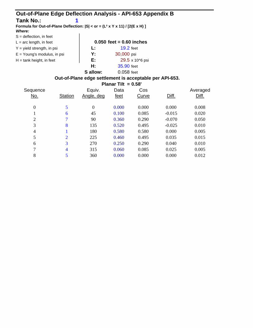
Out-of-Plane Edge Deflection Analysis - API-653 Appendix BTank No.: 1Formula for Out-of-Plane Deflection: |S| < or = (L² x Y x 11) / [2(E x H) ]Where:S = deflection, in feetL = arc length, in feet 0.050 feet = 0.60 inchesY = yield strength, in psi L: 19.2 feetE = Young's modulus, in psi Y: 30,000 psiH = tank height, in feet E: 29.5 x 10^6 psi
H: 35.90 feetS allow: 0.058 feet
Out-of-Plane edge settlement is acceptable per API-653.Planar Tilt = 0.58'
Sequence Equiv. Data Cos AveragedNo. Station Angle, deg feet Curve Diff. Diff.
0 5 0 0.000 0.000 0.000 0.0081 6 45 0.100 0.085 -0.015 0.0202 7 90 0.360 0.290 -0.070 0.0503 8 135 0.520 0.495 -0.025 0.0104 1 180 0.580 0.580 0.000 0.0055 2 225 0.460 0.495 0.035 0.0156 3 270 0.250 0.290 0.040 0.0107 4 315 0.060 0.085 0.025 0.0058 5 360 0.000 0.000 0.000 0.012

Out-of-Plane Edge Deflection
0.000
0.100
0.200
0.300
0.400
0.500
0.600
0.700
5 6 7 8 1 2 3 4 5Station No.
Dis
tanc
e ab
ove
low
poi
nt, f
t.
Measured DataCosine Curve

EDGE SETTLEMENT CALCULATIONS SIDE 1Calculations per API Standard 653 Section B.3.4
TANK #: 1CLIENT: PORT OIL
LOCATION: PORTLAND, CTReference Templates ES-1 and ED-1
Bottom Radius Edge B2 Center Tank Angle of B in B ConditionWeld of Bend Elevation Elevation Elevation Diameter Weld to Tank Inches Allowable
Reading Reading Reading RadiusA WELD 2 6.67 6.59 5.96 49.00 52 0.44 2.04 Edge Settlement is AcceptableB WELD 2.6 6.58 6.54 5.96 49.00 29 0.11 2.37 Edge Settlement is AcceptableC WELD 2.6 6.48 6.46 5.96 49.00 8 0.15 2.51 Edge Settlement is AcceptableD WELD 2.6 6.43 6.42 5.96 49.00 10 0.01 2.49 Edge Settlement is AcceptableE WELD 2 6.38 6.31 5.96 49.00 30 0.66 2.10 Edge Settlement is AcceptableF WELD 2 6.4 6.3 5.96 49.00 55 0.91 2.03 Edge Settlement is Acceptable

EDGE SETTLEMENT CALCULATIONS SIDE 2Calculations per API Standard 653 Seciton B.3.4
TANK #: 1CLIENT: PORT OIL
LOCATION: PORTLAND, CTReference Templates ES-1 and ED-1
Bottom Radius Edge B2 Center Tank Angle of B in B ConditionWeld of Bend Elevation Elevation Elevation Diameter Weld to Tank Inches Allowable
Reading Reading Reading RadiusA WELD 3 6.96 6.65 5.96 49.00 56 2.79 2.44 Edge Settlement Exceeds the Initial Limits Per API-653B WELD 2.6 6.95 6.57 5.96 49.00 29 4.17 2.37 Edge Settlement Exceeds the Initial Limits Per API-653C WELD 3.2 6.93 6.53 5.96 49.00 8 4.67 2.86 Edge Settlement Exceeds the Initial Limits Per API-653D WELD 3.3 6.84 6.43 5.96 49.00 11 4.78 2.90 Edge Settlement Exceeds the Initial Limits Per API-653E WELD 3.4 6.81 6.49 5.96 49.00 32 3.33 2.79 Edge Settlement Exceeds the Initial Limits Per API-653F WELD 3.2 6.71 6.47 5.96 49.00 60 2.10 2.52 Edge Settlement is Acceptable

EDGE SETTLEMENT CALCULATIONS Calculations per API Standard 653 Section B.3.4
TANK #: 1CLIENT: PORT OIL
LOCATION: PORTLAND, CT
"A" Edge Calculations Reference Templates ES-1 and ED-1Bottom Radius Edge B2 Center Tank Angle of B in B ConditionWeld of Bend Elevation Elevation Elevation Diameter Weld to Tank Inches Allowable
Reading Reading Reading RadiusWELD A1 2.6 6.76 6.53 5.96 49.00 21 2.49 2.42 Edge Settlement Exceeds the Initial Limits Per API-653WELD A2 3 6.85 6.59 5.96 49.00 1 3.10 2.80 Edge Settlement Exceeds the Initial Limits Per API-653WELD A3 3 6.92 6.62 5.96 49.00 19 3.27 2.66 Edge Settlement Exceeds the Initial Limits Per API-653
"Last Row" Edge CalculationsBottom Radius Edge B2 Center Tank Angle of B in B ConditionWeld of Bend Elevation Elevation Elevation Diameter Weld to Tank Inches Allowable
Reading Reading Reading RadiusWELD LR1 2.6 6.45 6.32 5.96 49.00 19 1.40 2.43 Edge Settlement is AcceptableWELD LR2 2.6 6.51 6.33 5.96 49.00 0 2.16 2.56 Edge Settlement is AcceptableWELD LR3 2.6 6.58 6.36 5.96 49.00 19 2.47 2.43 Edge Settlement Exceeds the Initial Limits Per API-653

TEMPLATES
For Templates, Please refer to Templates File
MISSION STATEMENT “It is the mission of DJA Inspection Services, Inc. to provide full service tank inspections to the storage tank industry, to be known for quality and detailed inspections through the dedication and experience of our team and to provide the service worldwide as well as to the individual tank owner.”
DRAWINGS
MISSION STATEMENT “It is the mission of DJA Inspection Services, Inc. to provide full service tank inspections to the storage tank industry, to be known for quality and detailed inspections through the dedication and experience of our team and to provide the service worldwide as well as to the individual tank owner.”


PHOTOS
MISSION STATEMENT “It is the mission of DJA Inspection Services, Inc. to provide full service tank inspections to the storage tank industry, to be known for quality and detailed inspections through the dedication and experience of our team and to provide the service worldwide as well as to the individual tank owner.”


CERTIFICATION
For Certifications, Please refer to Inspector Certification File
MISSION STATEMENT “It is the mission of DJA Inspection Services, Inc. to provide full service tank inspections to the storage tank industry, to be known for quality and detailed inspections through the dedication and experience of our team and to provide the service worldwide as well as to the individual tank owner.”

RAW DATA
Hand written field obtain data will be available upon request.
MISSION STATEMENT “It is the mission of DJA Inspection Services, Inc. to provide full service tank inspections to the storage tank industry, to be known for quality and detailed inspections through the dedication and experience of our team and to provide the service worldwide as well as to the individual tank owner.”