d ig ital c o m m u n icatio n s i - university of cambridge · d ig ital c o m m u n icatio n s i...
TRANSCRIPT

Digital Communications I(Introduction to Digital Communications)
Lent Term — 2008
Andrew W [email protected]


Topic 1: Introduction
Course aims:
The aims of this course are to develop an understanding ofcommunications networks from a wide perspective, within aframework of principles rather than technologies orarchitectures.
Technologies and architectures will, however, be used asexamples and motivation.
Feedback’s useful at any pointe-mail [email protected]
Introduction Slide 1-1

Mechanics — subject to revision
Subject Mechanics
➤ All lectures are in William Gates Bulding, LT1
➤ 7 Weeks of Lectures (Tuesday and Thursday);12 ! 50 minute lectures
➤ 2 lectures a week: Tuesday 1200-1300, Thursday1200-1300
Lecturer Mechanics
➤ Australian (AQI)
➤ email me [email protected], BUT add thekeyword dc1 to the subject
Introduction Slide 1-2

Context 1 — Systems informs Networking
For a Systems-centric perspective...
➤ Why does this pyramid exist?
➤ What do we do to mitigate (reduce) its impact?
➤ Where is the important information?
➤ What is the important information?
➤ How can I keep the beast fed? (keep the CPU doingsomething useful?)
➤ How can I get the best e!ciency from the WAN?
Introduction Slide 1-3

Context 2 – Multiplexing
Sharing makes things e!cient.
➤ One airplane/train for 100 people
➤ One telephone for many calls
➤ One lecture theatre for many classes
➤ One computer for many tasks
➤ One network for many users
Disadvantages of Multiplexing?
➤ Might have to wait
➤ Might not know how long you have to wait
➤ Might never get served
Multiplexing is the action of sharing of common resources.
This links back to Concurrent Systems and Applications:Concurrency is all about how common resources are shared.
Introduction Slide 1-4

Books
Most networking books actually tackle communication in atechnology oriented way, so lectures will tend to slice across atext. There is no definitive book — sorry. However, the firston this list is a pretty good starting point.
➤ Recommended Peterson and Davie, Computer Networks:A Systems Approach, Morgan Kaufman
➤ Halsall, Data Communications, Computer Networks, andOSI, Addison-Wesley
➤ Tanenbaum, A.S. Computer Networks, Prentice-HallInternational
➤ Stallings, Data and Computer Communications, Macmillan
➤ Douglas Comer, Internetworking with TCP/IP volume I,Prentice-Hall International. (definitive - high level)
➤ Douglas Comer, Internetworking with TCP/IP volume II,Prentice-Hall International. (definitive - theinner-workings)
Introduction Slide 1-5

Digital Communications I
➤ Layering
➤ Physical Transmission
➤ Modulation
➤ Coding
➤ Compression
➤ Multiplexing
➤ Protocol & State
➤ Names, Addresses, Routes
➤ The Internet
➤ Standards
Topic 2: Computer Networks
Overview of this section
➤ Digital Communications
➤ Digital Media
➤ Books
➤ Tale of Two Networks
Digital Communications I Slide 2-1

What is Digital Communications?
Is it:
➤ how I get bits down a wire?
➤ how I join these “wires” together to build a network?
➤ what I can do given that I can get bits across a network?
Yes — a wide field, Digital Communications covers all of thesefields.
Need to call on wide range of knowledge:
➤ mathematics: error detection, error correction, encryption
➤ physics: optics, propagation
➤ electrical engineering: modulation, noise
➤ computer science: algorithms, architecture, protocolspecification...
Digital Communications I Slide 2-2

An Aside: Why Digital for Video and Audio?
➤ maintaining fidelity using error correction (eg CDs)
➤ more flexible control (eg DVD vs. VHS cassette)
➤ large scale integration of switching equipment, ease ofcompacting in time and reusing components — eg thedigital telephone network
➤ large scale integration of processing
➤ digital signal processors➤ digital signal processing by general purpose processors
➤ the myth of “infinite precision” analog
Digital Communications I Slide 2-3

Metacomments and Books
➤ principles not technologies (but technology as examples)
➤ communication changing rapidly; communications andcomputing becoming unified
➤ emphasis on “higher levels” not how to get bits down awire
Books and References
Most books actually tackle communication in a technologyoriented way, so lectures will tend to “cut across” a text.
A favourite is:
Computer Networks: A Systems Approach, Peterson andDavie, 3rd Ed, Morgan Kaufman
Other good ones are:
Data Communications Computer Networks and OSI,Halsall, 2nd Ed, Addison Wesley
Data and Computer Communications, Stallings, 2nd Ed,MacMillan
Telecommunications: Protocols and Design, Spragins et alAddison Wesley
Digital Communications I Slide 2-4

A very interesting paper is:
Ethernet: Distributed Packet Switching for Local ComputerNetworks, Metcalfe and Boggs, in Communications of theACM, Vol 19 No 7.
Digital Communications I Slide 2-5
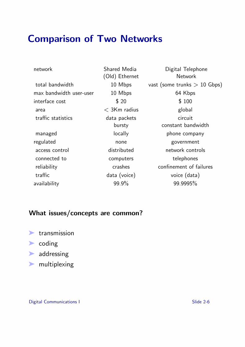
Comparison of Two Networks
network Shared Media Digital Telephone(Old) Ethernet Network
total bandwidth 10 Mbps vast (some trunks > 10 Gbps)
max bandwidth user-user 10 Mbps 64 Kbps
interface cost $ 20 $ 100
area < 3Km radius global
tra!c statistics data packets circuitbursty constant bandwidth
managed locally phone company
regulated none government
access control distributed network controls
connected to computers telephones
reliability crashes confinement of failures
tra!c data (voice) voice (data)
availability 99.9% 99.9995%
What issues/concepts are common?
➤ transmission
➤ coding
➤ addressing
➤ multiplexing
Digital Communications I Slide 2-6

Exercises
➤ [2-1] Consider new audio and video devices in your homeand work-place;
(i ) Concentrating upon Digital devices (e.g. DVD, CD,MP3 player), what additional facilities do they have,in-contrast with their analog predecessor ?
(ii ) Are they networked? Could they be? What wouldyou use such a network for?
➤ [2-2] Is your phone digital or analog or both? How can youtell?
➤ [2-3] Consider and compare the phone and postal systemusing the criteria of transmission, coding, addressing, andmultiplexing.
Digital Communications I Slide 2-7
Topic 3: Abstraction
Previous topic
➤ What is Digitial Communications?
➤ Why use Digital?
➤ Metacomments and Books
Overview of this topic
➤ Terminology
➤ abstraction➤ layering➤ entities➤ peers➤ channels
Digital Communications I Slide 3-1
Abstraction
Abstraction — a mechanism for breaking the problem down.
➤ what not how; don’t need to know how a function isperformed in order to understand how it fits into a largersystem
➤ eg specification versus implementation
➤ eg Modules in programs
➤ tool for managing complexity
➤ allows replacement of implementation without adverselya"ecting system behaviour
“Vertical” versus “Horizontal”
➤ “Vertical” One obvious way of splitting functionality up isto think about what happens in, say, physical box. “Howdoes it attach to the next physical box” or “How do Iconnect my computer to the Internet?”
➤ “Horizontal” Perhaps less obvious at first, but think aboutcommunication paths running through the system ratherthan the boxes in the system. Key observation is thatpaths are built on top of (“layered over”) other paths.
Digital Communications I Slide 3-2

Layering
➤ restricted form of abstraction in which system function isdivide into layers, one built on top of another
➤ sometimes layered structure referred to as a “stack”,having nothing to do with the data structure.
Example: Networked File System
NFS
SUN Remote Procedure Call
User Datagram Protocol (UDP)
Internet Protocol (IP)
Ethernet Packets
Digital Communications I Slide 3-3

Layering examples - II
Example: Telephone Network
8 KByte per sec stream
Framed Byte Stream
Analog signal
Bitstream
8 K 12 bit samples per sec
7 KHz analog voice
phonemes
words
thoughts
modulation
framing
multiplexing
companding
D/A, A/D
speaking 3
speaking 2
speaking 1
Digital Communications I Slide 3-4

Layers and Communication
n layer
n - 1 layer
n + 1 layer
➤ interaction only between layers one level apart
➤ n layer makes use of services provided by n " 1 layer andprovides service to n + 1 layer
➤ top layer is “application”, something that does somethinguseful (except some applications are built on top of otherapplications)
➤ bottom layer is physical media
Digital Communications I Slide 3-5

Entities and Peers
4
2
1
3
4
2
1
3
➤ entity — that which has independent existence, in otherwords a thing
➤ entities are the things in layers which interact with thethings in the layers above and below.
➤ entities communicate with peer entities which are at thesame level in the layered stack but at a di"erent place, ega di"erent machine, a di"erent person.
➤ distinguish local interaction from peer to peercommunication
➤ communication between peers supported by the entities atlower layers
➤ entities usually do something useful, like A/D D/A,encryption, error correction, but entities that do absolutelynothing are perfectly reasonable
Digital Communications I Slide 3-6

4
2
1
3
4
2
1
3
2
1 1
➤ not all communication is end to end!
➤ examples for thing in the middle:
➤ IP router➤ microwave repeater➤ telephone switch➤ person in the middle relaying messages➤ person in the middle translating French to English
Digital Communications I Slide 3-7

Channels
➤ peer entities communicate over channels and supportcommunication for higher layer peers by providing themwith higher layer channel
➤ channel in this sense is a very abstract term (refer to thevoice on digital telephony stack).
A channel is that into which an entity puts symbols andwhich causes those symbols (or a reasonable approximation)to appear somewhere else at a later point in time.
symbols in symbols out
channel
Digital Communications I Slide 3-8

Channel Characteristics
➤ symbol type: analog waveform, bits, packets
➤ capacity: bandwidth, data rate, packet rate
➤ delay: fixed or variable
➤ fidelity: signal to noise, bit error rate, packet error rate
➤ cost: per attachment, per call, for capacity consumed
➤ reliability
➤ security: privacy, unforgability
➤ order preserving: always, almost always, usually
➤ connectivity: point to point, 1 to many, many to many
Examples of channels
➤ a piece of coaxial cable
➤ a 64 Kbps channel in a telephone network
➤ the sequence of packets transmitted from one host toanother on an Ethernet
➤ a telephone call (handset to handset)
➤ the audio channel in a room
➤ the sequence of words exchanged by two people in a room
➤ a diplomatic channel
Digital Communications I Slide 3-9

Layering and Embedding
➤ often in data communications, we see higher layerinformation embedded in lower layer information.
➤ for example take our remote file server example
IP layer information
UDP layer information
RPC layer info
hdr trailer
hdr
hdr
Ethernet
IP
UDP
RPC Layer hdr
➤ this is embedding and can certainly be viewed as a form oflayering
➤ information for higher layers is found by stripping o"headers and trailers which are the only informationprocessed at that layer.
➤ for example an IP entity only looks at IP headers in packets
BUT IT IS NOT THE ONLY FORM OF LAYERING
Digital Communications I Slide 3-10

Layering and Implementation
Picture from Halsall’s book:
Layer (task) N+1
Layer (task) N
Layer (task) N-1
eg timer
This is one possible way of implementing a multilayer protocolstack in software. It is not the only or indeed in manycircumstances the best. Layering is a tool to help understandhow communication systems work, not to determineimplementation strategy.
Peterson is slightly weird on this too...
Digital Communications I Slide 3-11

Exercises
3-1 Abstraction is a form of breaking a problem down intoconstituent parts. Write down the modules involved whendriving into a petrol station to fill the car, pay the cashierand depart. Now identify the changes if you were payingwith a debit card or cash. Finally, identify the changes foryou driving a car to the local supermarket and then buyingan item from the local supermarket.
3-2 Abstraction is useful way to break-down a problem;layering is a simplified form of abstraction that iscommonly used to describe modern networks;
(i ) In the style of the slides earlier in this topic, sketchthe abstraction layers for a web-browser session.
(ii ) In slide 9, could the RPC of NFS be laid on top ofTCP instead of UDP? If so, Why? If not, Why-not?
3-3 In slide 3-3, the Telephone Network as an example oflayering, assuming a multiplex of 10 channels and noframing overhead, estimate what channel capacity isrequired at the lowest level?
Digital Communications I Slide 3-12

Topic 4: Physical Transmission
Previous topic
➤ Terminology
➤ abstraction➤ layering➤ entities➤ peers➤ channels
Overview of this topic
➤ Transmission Media
➤ Characteristics (Fundamental Limits, Noise, Attenuation),Bandwidth vs Signal to Noise)
➤ Digital Channels
➤ Synchronization
➤ Modulation
Digital Communications I Slide 4-1

Physical Transmission
➤ How do I get bits down a piece of wire?
➤ Physical transmission is the lowest layer function (except,perhaps, how I lay cable) we are usually concerned with
➤ We are concerned with turning an analog channel into adigital channel
analog channel digital channel
physical layer entities
Physical layer entities:
➤ make use of the “services” provided by the transmissionmedium
➤ usually model the transmission media as an analog channel
➤ translate bit stream into a representation suitable fortransmission on the medium and retranslate back
➤ provide the service of a digital channel
Digital Communications I Slide 4-2
Transmission Media
➤ acoustic
➤ electronic, guided and unguided
➤ optical, guided and unguided (eg smoke signals)
➤ what are the common considerations?
➤ what is this “service”
➤ not concerned with why
Digital Communications I Slide 4-3

Characteristics: Fundamental Limits
➤ symbol type: generally an analog waveform — voltage,current, photo-intensity etc
➤ capacity: bandwidth
➤ delay: speed of light (or sound) in medium and distance
➤ fidelity: signal to noise ratio
Bandwidth
➤ measure of the range of frequencies of sinusoidal signalthat channel supports.
➤ eg a channel that supports sinusoids from 1 MHz to 1.1MHz has a bandwidth of 100 KHz.
➤ “supports” in this context means “comes out the other endof the channel”
➤ some frequencies supported better than others
➤ analysing what happens to an arbitrary waveform is doneby examining what happens to its component sinusoids #Fourier analysis
➤ bandwidth is a resource
Digital Communications I Slide 4-4

Brief Excursion into Fourier Analysis
square wave with period 2π “is”
sin(x) +1
3sin(3x) +
1
5sin(5x) + ...
sin(x)
sin(x) +1
3sin(3x)
Digital Communications I Slide 4-5

Excursion (cont’d)
sin(x) +1
3sin(3x) +
1
5sin(5x)
sin(x) +1
3sin(3x) +
1
5sin(5x) +
1
7sin(7x)
Digital Communications I Slide 4-6

Excursion (conclusion)
➤ square waves have high frequency components in them
➤ channels which attenuate di"erent frequencies di"erentlywill change the shape of the signal
➤ choose signals for transmission accordingly
Digital Communications I Slide 4-7

Noise
Noise
Source ReceiverChannel
➤ receiver gets something related to the transmitted signalplus noise
➤ noise may be systematic or random
➤ systematic noise from interfering equipment
➤ can in principle be eliminated (but not always convenient)
➤ Never buy a Monday car joke
➤ random noise caused by thermal vibration (thermal noise)
➤ “white” power evenly distributed across frequencies
➤ signal to noise ratio SN
➤ more distance more noise
➤ receiver (clearly) throws away noise not in the band offrequencies it is receiving
Digital Communications I Slide 4-8
Attenuation
➤ signal looses energy as it travels along a channel
➤ radiation loss: in many media, higher the frequency, higherthe radiation loss
➤ absorption by media — eg water molecules — thenre-emitted as noise
➤ spatial dispersion
Attenuation is function of channel length, transmissionmedium, and signal frequencies
Digital Communications I Slide 4-9
Bandwidth versus Signal to Noise
➤ what’s better: high bandwidth or low signal to noise?
➤ for channels with white noise have information capacity Cmeasured in bits per second, of a channel
C = Blog2(1 + S/N)
where B is the bandwidth of the channel and S/N is theratio of received signal power to received noise power.
➤ (This is actually NOT the definition of informationcapacity; it is derived from the definition)
➤ channels with no noise have infinite information capacity
➤ channels with any signal have nonzero information capacity
➤ channels with signal to noise ratio of unity have aninformation capacity in bits per second equal to itsbandwidth in hertz
Digital Communications I Slide 4-10
Digital Channels
➤ service that physical layer provides
➤ consider them to be fixed rate for now
➤ symbols are discrete values which are sent on the channelat fixed rate
➤ symbols need not be binary
➤ baud rate is the rate at which symbols can be transmitted
➤ data rate (or bit rate) is the equivalent number of binarydigits which can be sent
➤ for example if symbols are quaternary with rate R then thedata rate is 2 ! R.
➤ fidelity of the channel usually measured as a bit error rate— the probability that a bit sent as a 1 was interpreted asa 0 by the receiver or vice versa.
Digital Communications I Slide 4-11
Modulation
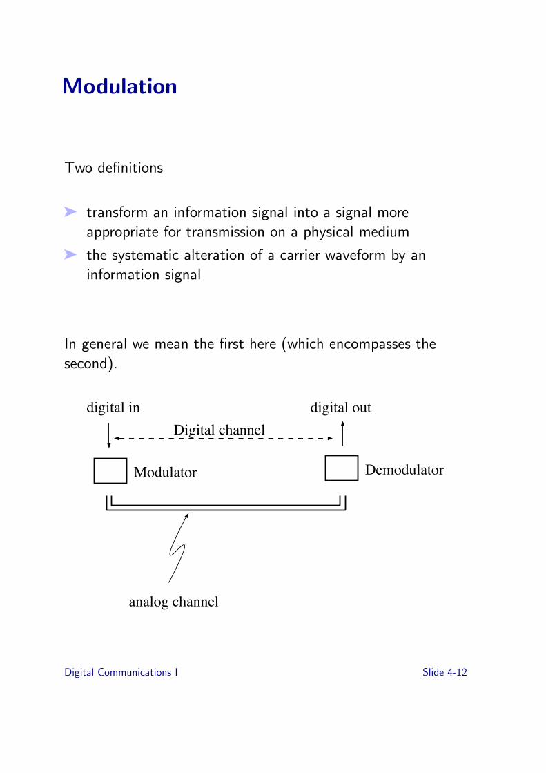
Two definitions
➤ transform an information signal into a signal moreappropriate for transmission on a physical medium
➤ the systematic alteration of a carrier waveform by aninformation signal
In general we mean the first here (which encompasses thesecond).
analog channel
Modulator Demodulator
digital in digital outDigital channel
Digital Communications I Slide 4-12

Baseband versus Broadband
➤ baseband is not modulated on a carrier
➤ broadband is, either for bandwidth sharing purposes orpropagation purposes (radio, TV, satellite)
Baseband Modulation
A baseband signal
How many ones?
Digital Communications I Slide 4-13

Synchronisation
➤ receiver needs to know where data bits boundaries are
➤ two ways
➤ asynchronous➤ transmission is sporadic, divided into frames➤ receiver and transmitter have oscillators which are
close in frequency producing tx clocks and rx clock.➤ receiver synchronises the phase of the rx clock with
the tx clock by looking at one or more bit transitionsat the beginning of a frame
➤ rx clock drifts with respect to the tx clock but stayswithin a fraction of a bit of tx clock throughout theduration of a frame
➤ transmission time is limited by accuracy of oscillators➤ synchronous
➤ transmission is continuous➤ receiver continually adjusts its frequency to track
clock from incoming signal➤ requires bit transitions➤ phase locked loop: rx clock predicts when incoming
clock will change and corrects slightly when wrong.
Digital Communications I Slide 4-14

Asynchronous Transmission
0 1 2 3 4 5 6 7
parity bitstart bit
stop bits
➤ start bit tells receiver where first bit edge is
➤ receiver must stay synchronised for 9 bits
➤ stop bits allow receiver time to recover (ie get ready fornext start bit)
➤ next start bit can be anytime later
Digital Communications I Slide 4-15
Synchronous Transmission
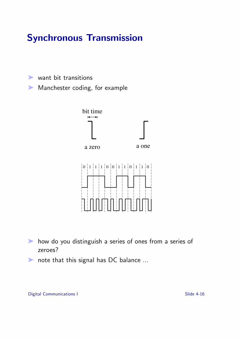
➤ want bit transitions
➤ Manchester coding, for example
a zero a one
bit time
0 01 1 1 0 1 1 1 10 0
➤ how do you distinguish a series of ones from a series ofzeroes?
➤ note that this signal has DC balance ...
Digital Communications I Slide 4-16

Broadband Modulation
➤ carrier frequency which is modulated
Carrier : Acos(2πfct)
Information : x(t)
Amplitude Modulation : A(mx(t) + 1)cos(2πfct)
Digital Communications I Slide 4-17
Frequency and Phase Modulation
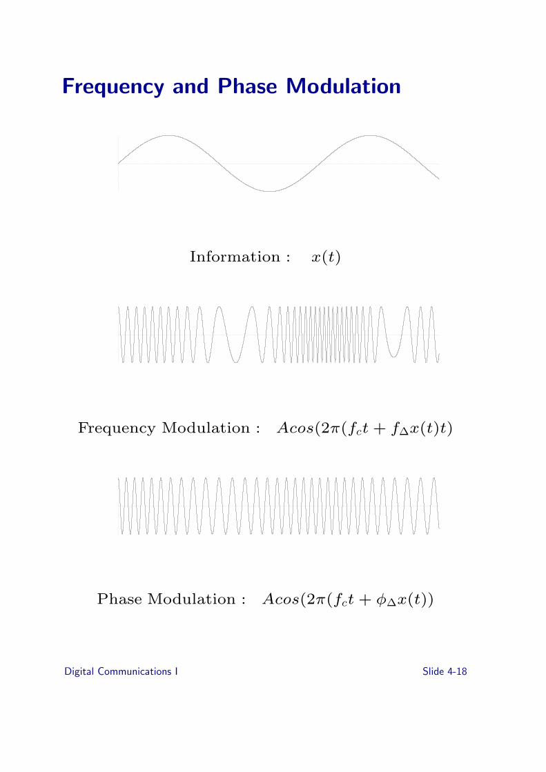
Information : x(t)
Frequency Modulation : Acos(2π(fct + f!x(t)t)
Phase Modulation : Acos(2π(fct + φ!x(t))
Digital Communications I Slide 4-18
Broadband Modulation With Digital Information
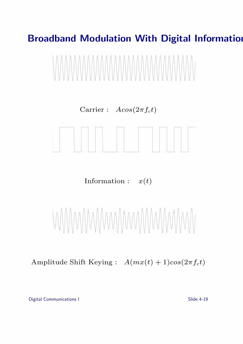
Carrier : Acos(2πfct)
Information : x(t)
Amplitude Shift Keying : A(mx(t) + 1)cos(2πfct)
Digital Communications I Slide 4-19

Digital Frequency and Phase Modulation
Information : x(t)
Frequency Shift Keying : Acos(2π(fct + f!x(t)t)
Digital Communications I Slide 4-20

Carrier :
Phase Shift Keying : Acos(2π(fct + φ!x(t))
Digital Communications I Slide 4-21

Phase Shift Keying Finale
➤ in practice one would filter to remove instantaneouschanges in phase
➤ binary phase shift keying (BPSK) is shown but can havemore than two levels, eg quaternary phase shift keying(QPSK)
➤ phase changes can be synchronised to the carrier frequency(coherence)
➤ possible to have more than one bit per hertz
Digital Communications I Slide 4-22

Exercises
4-1 Compare the forms of modulation described in this Topic
4-2 Show a single modulation technique can achieve 2bits/second for each change in the line
4-3 Read up on the definition of Baud, compare this with thedefinition of bits-per-second.Can Baud ever be less than bits-per-second for the samecommunications channel? Why? Why-not?Can Baud ever be greater than bits-per-second for thesame communications channel? Why? Why-not?
4-4 Describe using a single physical transmission channel,examples of the following:
(i ) Attenuation(ii ) Systematic Noise(iii ) Random Noise(iv ) Bandwidth(v ) Signal to Noise (Ratio)
4-5 Compare two methods of synchronization, use at least fourcriteria
Digital Communications I Slide 4-23

1
Digital Communications I
Topic 5-bis : Coding Data
Goal of Lecture
• Understand what coding is.• Understand how error correction or detection
codes work.

2
MyPasswd
AA$$$$ff
MyPasswd
AA$$$$ff
AA$$$$ffff AA$$$$ffff
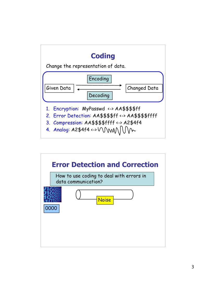
CodingChange the representation of data.
Given Data Changed Data
Encoding
Decoding
3
CodingChange the representation of data.
Given Data Changed Data
Encoding
Decoding
1. Encryption: MyPasswd <-> AA$$$$ff2. Error Detection: AA$$$$ff <-> AA$$$$ffff3. Compression: AA$$$$ffff <-> A2$4f44. Analog: A2$4f4 <->
Error Detection and Correction How to use coding to deal with errors in
data communication?
Noise0000

4
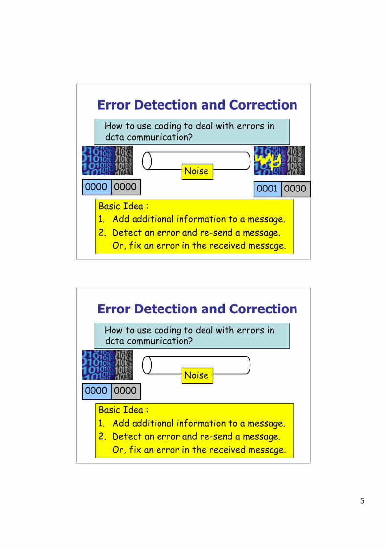
How to use coding to deal with errors indata communication?
Noise0000
Basic Idea :1. Add additional information to a message.2. Detect an error and re-send a message. Or, fix an error in the received message.
Error Detection and Correction
How to use coding to deal with errors indata communication?
Noise0000
Basic Idea :1. Add additional information to a message.2. Detect an error and re-send a message. Or, fix an error in the received message.
0000
Error Detection and Correction
5
How to use coding to deal with errors indata communication?
Noise0000 0001
Basic Idea :1. Add additional information to a message.2. Detect an error and re-send a message. Or, fix an error in the received message.
0000 0000
Error Detection and Correction
How to use coding to deal with errors indata communication?
Noise0000
Basic Idea :1. Add additional information to a message.2. Detect an error and re-send a message. Or, fix an error in the received message.
0000
Error Detection and Correction

6
How to use coding to deal with errors indata communication?
Noise0000 0000
Basic Idea :1. Add additional information to a message.2. Detect an error and re-send a message. Or, fix an error in the received message.
0000 0000
Error Detection and Correction
Error Detection CodeSender:Y = generateCheckBit(X);send(XY);
Receiver:
receive(X1Y1);Y2=generateCheckBit(X1);if (Y1 != Y2) ERROR;else NOERROR
Noise

7
Error Detection CodeSender:Y = generateCheckBit(X);send(XY);
Receiver:
receive(X1Y1);Y2=generateCheckBit(X1);if (Y1 != Y2) ERROR;else NOERROR
Noise
Error Detection CodeSender:Y = generateCheckBit(X);send(XY);
Receiver:
receive(X1Y1);Y2=generateCheckBit(X1);if (Y1 != Y2) ERROR;else NOERROR
Noise

8
Error Detection CodeSender:Y = generateCheckBit(X);send(XY);
Receiver:
receive(X1Y1);Y2=generateCheckBit(X1);if (Y1 != Y2) ERROR;else NOERROR
Noise
Error Detection CodeSender:Y = generateCheckBit(X);send(XY);
Receiver:
receive(X1Y1);Y2=generateCheckBit(X1);if (Y1 != Y2) ERROR;else NOERROR
Noise
==

9
Error Detection Code: ParityAdd one bit, such that the number of 1’s is even.
Noise0000 0
0001 1
1001 0
Error Detection Code: ParityAdd one bit, such that the number of 1’s is even.
Noise0000 0
0001 1
1001 0
0001 0
0001 1
1111 0
10
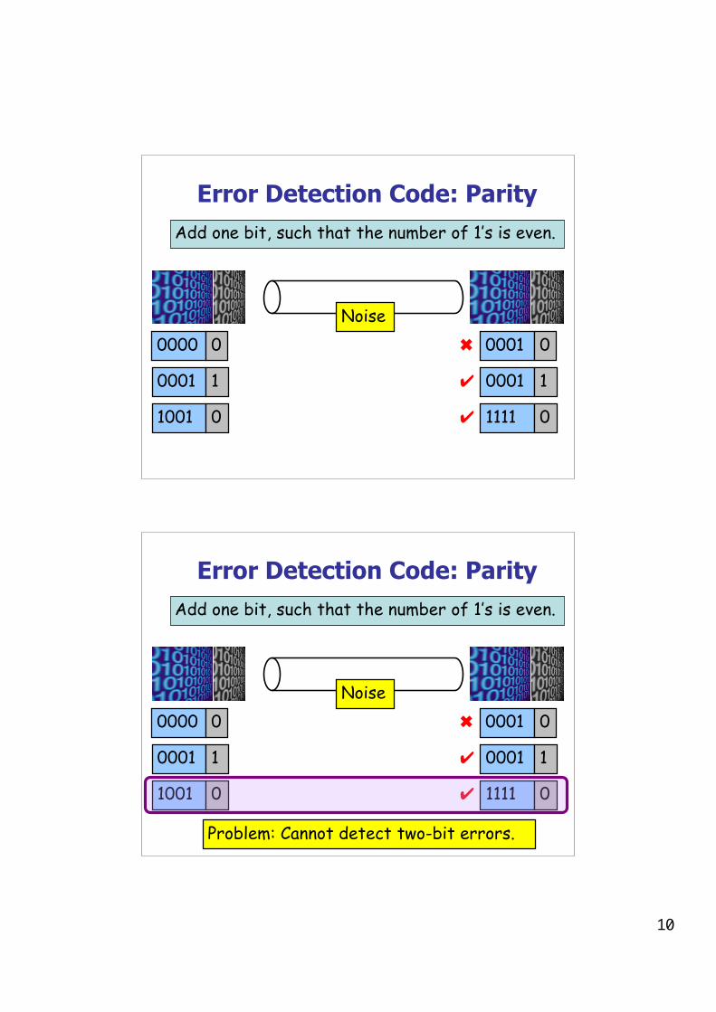
Error Detection Code: ParityAdd one bit, such that the number of 1’s is even.
Noise0000 0
0001 1
1001 0
0001 0
0001 1
1111 0
✖
✔
✔
Error Detection Code: ParityAdd one bit, such that the number of 1’s is even.
Noise0000 0
0001 1
1001 0
0001 0
0001 1
1111 0
✖
✔
✔
Problem: Cannot detect two-bit errors.

11
Error Detection Code: CRC
• CRC means “Cyclic Redundancy Check”.• More powerful than parity.• It can detect various kinds of errors, including
2-bit errors.• Uses more math: multiplication, binary division.• Parameterized by n-bit divisor P.• Example: 3-bit divisor 101.• Choosing good P is crucial.
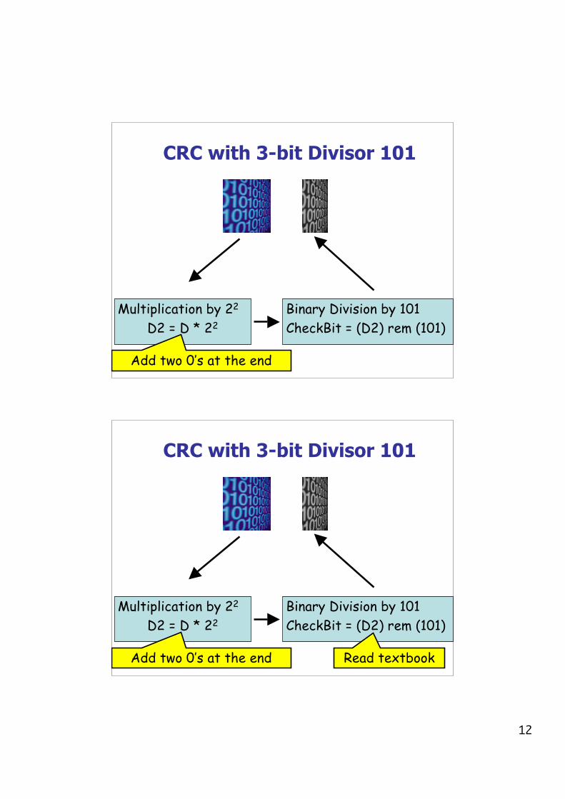
CRC with 3-bit Divisor 101
Multiplication by 22
D2 = D * 22Binary Division by 101CheckBit = (D2) rem (101)
12
CRC with 3-bit Divisor 101
Multiplication by 22
D2 = D * 22Binary Division by 101CheckBit = (D2) rem (101)
Add two 0’s at the end
CRC with 3-bit Divisor 101
Multiplication by 22
D2 = D * 22Binary Division by 101CheckBit = (D2) rem (101)
Add two 0’s at the end Read textbook

13
CRC with 3-bit Divisor 101
Multiplication by 22
D2 = D * 22Binary Division by 101CheckBit = (D2) rem (101)
1001
Add two 0’s at the end Read textbook
1111
CRC with 3-bit Divisor 101
Multiplication by 22
D2 = D * 22Binary Division by 101CheckBit = (D2) rem (101)
1001
100100
Add two 0’s at the end Read textbook
111100
1111

14
CRC with 3-bit Divisor 101
Multiplication by 22
D2 = D * 22Binary Division by 101CheckBit = (D2) rem (101)
1001
100100
11
Add two 0’s at the end Read textbook
00
111100
1111
CRC with 3-bit Divisor 101
Multiplication by 23
D2 = D * 23Binary Division by 101CheckBit = (D2) rem (101)
1001
1001000
11
Add three 0’s at the end Read textbook
00
1111000
1111
0
0
CRC Paritysame check bits from Parity,but different ones from CRC

15
Divisor -- Secret of CRC
• If the divisor were 100, instead of 101, data 1111and 1001 would give the same check bit 00.
• Mathematical analysis about the divisor:– Last bit should be 1.– Should contain at least two 1’s.– Should be divisible by 11.
• ATM, HDLC, Ethernet each use a CRC with well-chosen fixed divisors.
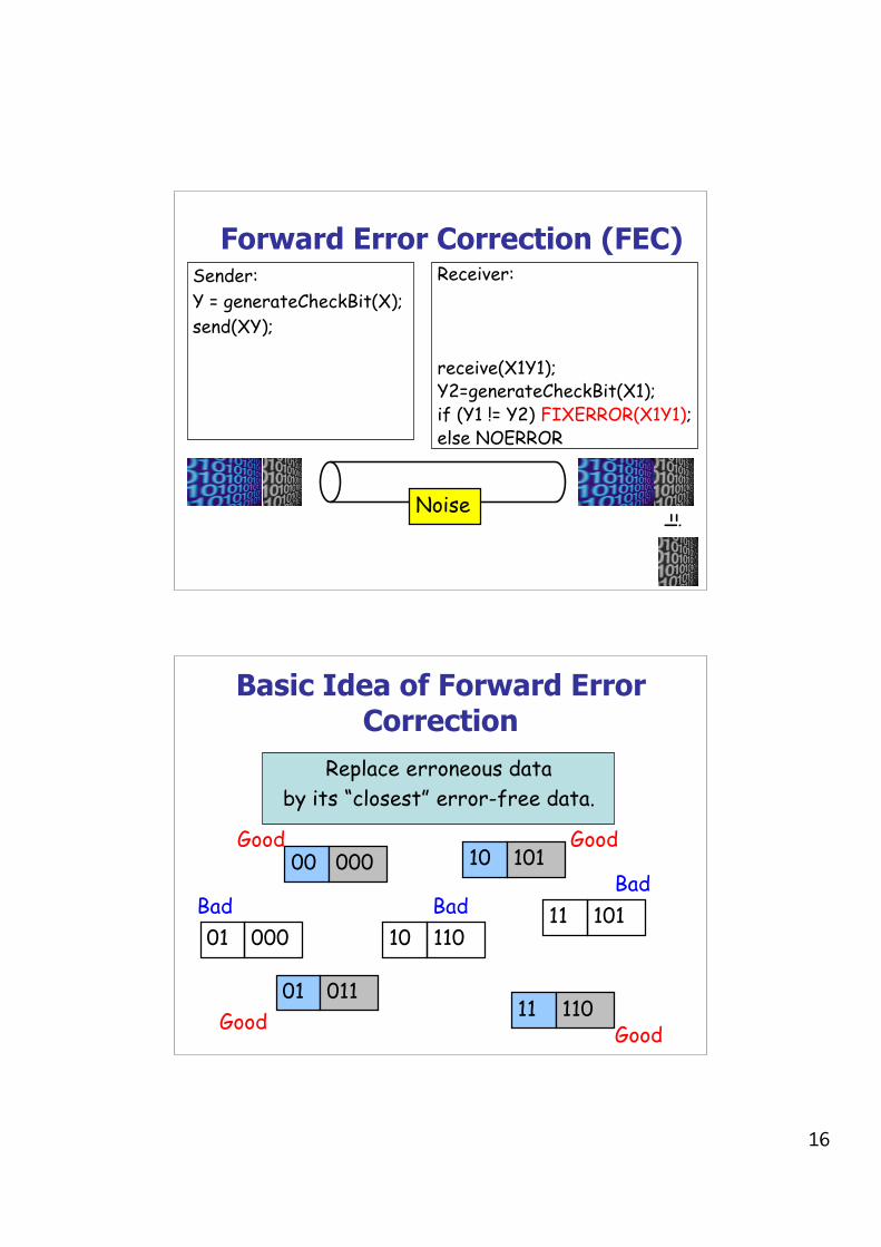
Forward Error Correction (FEC)Sender:Y = generateCheckBit(X);send(XY);
Noise
!=
Receiver:
receive(X1Y1);Y2=generateCheckBit(X1);if (Y1 != Y2) FIXERROR(X1Y1);else NOERROR
16
Forward Error Correction (FEC)Sender:Y = generateCheckBit(X);send(XY);
Noise
!=
Receiver:
receive(X1Y1);Y2=generateCheckBit(X1);if (Y1 != Y2) FIXERROR(X1Y1);else NOERROR
Basic Idea of Forward ErrorCorrection
Replace erroneous databy its “closest” error-free data.
00 000
01 011
10 101
11 110
01 000 11 101
10 110
Good
Good Good
Good
Bad Bad Bad

17
Basic Idea of Forward ErrorCorrection
Replace erroneous databy its “closest” error-free data.
00 000
01 011
10 101
11 110
01 000 11 101
10 110
Good
Good Good
Good
Bad Bad Bad
Basic Idea of Forward ErrorCorrection
Replace erroneous databy its “closest” error-free data.
00 000
01 011
10 101
11 110
01 000 11 101
10 110
Good
Good Good
Good
Bad Bad Bad
3
4
2
1

18
Basic Idea of Forward ErrorCorrection
Replace erroneous databy its “closest” error-free data.
00 000
01 011
10 101
11 110
01 000 11 101
10 110
Good
Good Good
Good
Bad Bad Bad
Error Detection vs CorrectionError Correction:• Cons: More check bits. False recovery.• Pros: No need to re-send.Error Detection:• Cons: Need to re-send.• Pros: Less check bits.Usage:• Correction: A lot of noise. Expensive to re-send.• Detection: Less noise. Easy to re-send.• Can be used together.

Topic 5: Coding Data
Previous topic
➤ Transmission Media
➤ Characteristics (Fundamental Limits, Noise, Attenuation),Bandwidth vs Signal to Noise)
➤ Digital Channels
➤ Synchronization
➤ Modulation
Overview of this topic
➤ Coding
➤ Digitization and Sampling
➤ Error Detection and Correction
➤ Block Codes➤ Information Theory➤ Compression➤ Encryption
Digital Communications I Slide 5-1

Coding
Channel
DecodingEncoding
informationinformation
symbolssymbols
➤ encoding takes information and turns it into symbolswhich are to be transmitted on a channel
➤ decoding takes symbols from a channel and turns theminto information for a higher layer
➤ symbols for one entity is information for another
➤ using coding as a general concept; includes A/D,modulation, etc
Digital Communications I Slide 5-2

Examples
➤ modulation used to represent digits on a physical medium;
➤ digitization of analog signals;
➤ error detection and correction codes used to determine ifa transmission error has occurred, and perhaps to correctit;
➤ compression coding used to reduce the amount of data(and therefore usually the data rate) which needs to besent;
➤ cipher coding used to protect the privacy of information asit travels through a channel, and
➤ delineation coding (framing) used to group symbols intological units,
➤ application level coding which provides applications withan agreement as to how data items are to be represented.
Digital Communications I Slide 5-3

Digitization of Analog Signals
➤ D/A, A/D di!erent from modulation, demodulation
➤ digital because:
➤ ease of handling and storage➤ ease of time dilation➤ noise (bit error rate) is not linearly cumulative with
processing and in principle (and practice) can bereduced to arbitrary levels
➤ introduces a one time quantisation noise
Digital Communications I Slide 5-4
Sampling
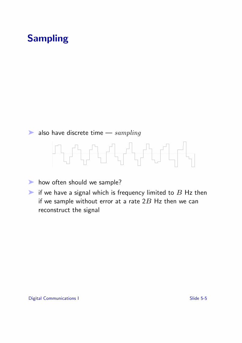
➤ also have discrete time — sampling
➤ how often should we sample?
➤ if we have a signal which is frequency limited to B Hz thenif we sample without error at a rate 2B Hz then we canreconstruct the signal
Digital Communications I Slide 5-5

Error Detection and Correction
➤ noise in physical channels give rise to bit errors
➤ some errors are acceptable in some applications — inparticular when it just adds noise to an analog signal whichhas been digitised.
➤ other applications are less tolerant
➤ either reduce error rate to acceptable level, or detectoccurrence of an error and retransmit information found tobe in error.
➤ reducing error rate might mean changing modulationtechnique or it may mean using error correction coding —sometimes called forward error correction (FEC)
Digital Communications I Slide 5-6

Forward Error Correction
➤ relies on providing redundant information
➤ trivial example, send every bit of information three timesand use majority voting. (improves error rate but burns updata rate)
➤ block codes are an important class of forward errorcorrecting codes in which information is divided intochunks.
➤ convolution codes which operate on continuous streamsare the other important class of FECs
Digital Communications I Slide 5-7

Block Codes
➤ information is divided into fixed sized messages, say oflength m
➤ messages are encoded into larger codewords of size k:
E : {0, 1}m !" {0, 1}k
where{0, 1}m denotes a bit string of length m.
➤ encoding mapping is one to one, but not onto; in otherwords for each message there is a unique codeword, butnot all elements of {0, 1}k are valid codewords.
➤ set of valid codewords is called the code.
➤ referred to as a (m, k) code.
➤ distance between two codewords is number of bits in whichthey di!er
➤ minimum distance, d of a code is the minimum distancebetween any pair of codewords
➤ decoding is done by looking at the received codeword,which may be corrupted, and finding the closest validcodeword (and then finding the message that encodes tothat valid codeword.
➤ can refuse to decode if su"ciently far away from a validcodeword, ie just report as an error
Digital Communications I Slide 5-8

➤ given minimum distance d can either detect up to d ! 1errors or correct (d ! 1)/2 errors or have an “inbetween”strategy.
➤ decoding is the hard part
Digital Communications I Slide 5-9
A simple (16, 25) Code
1 0 0 1 01 1 1 0 10 0 0 1 11 1 0 1 1
1 0 1 1 1
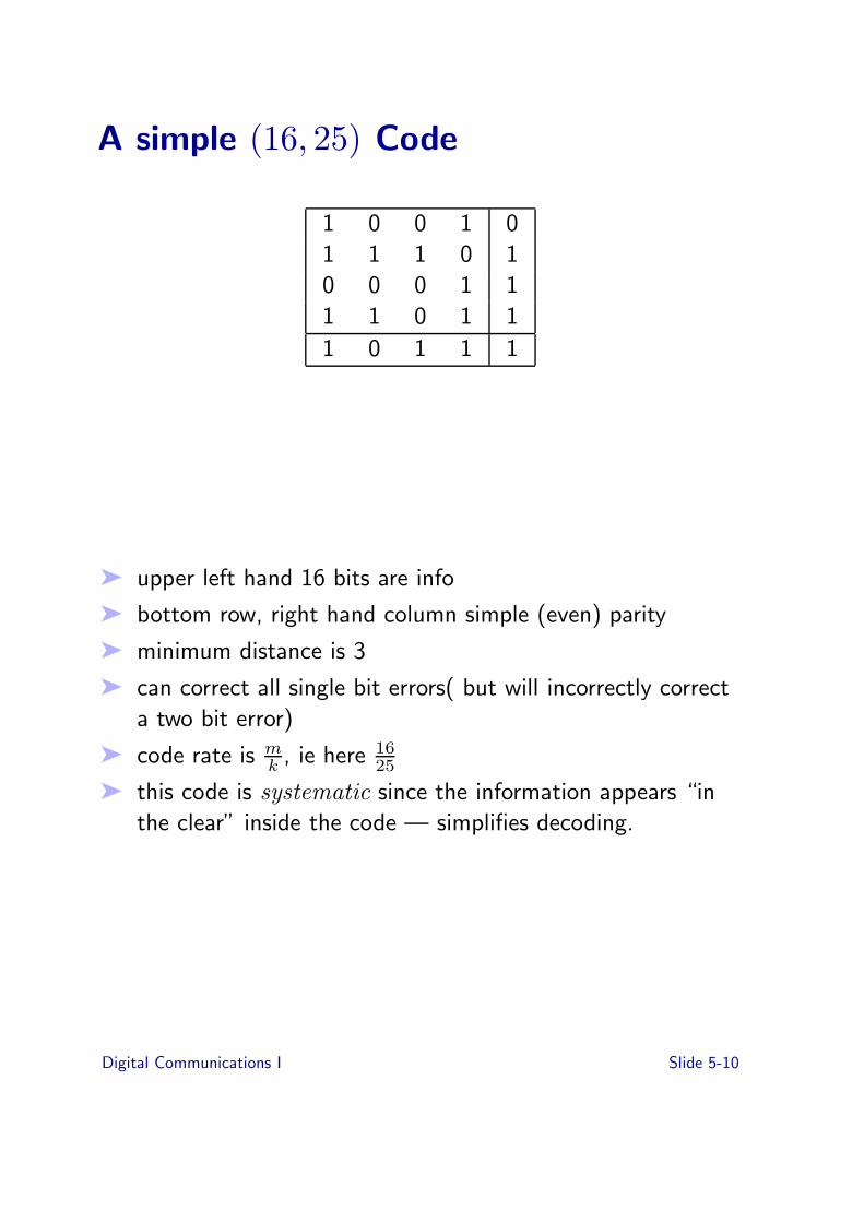
➤ upper left hand 16 bits are info
➤ bottom row, right hand column simple (even) parity
➤ minimum distance is 3
➤ can correct all single bit errors( but will incorrectly correcta two bit error)
➤ code rate is mk , ie here 16
25
➤ this code is systematic since the information appears “inthe clear” inside the code — simplifies decoding.
Digital Communications I Slide 5-10

Amazing Result of Information Theory
➤ given a digital channel with a bit error probability of of Pe,and any desired probability of correct decoding there existsa code with rate R arbitrarily close to
R < C = 1 + Pe log2 Pe + (1 ! Pe)log2 (1 ! Pe)
that will do it (note the log terms are negative).
➤ in fact, the definition of information for a binary channelwith data rate D is
I = D(1 + Pe log2 Pe + (1 ! Pe)log2 (1 ! Pe))
➤ note that for Pe = 12, I is 0 and that even for poor error
rates of Pe = 10!3, the capacity is greater than .98 # D.
the bad news...
➤ this result doesn’t tell us what the codes are
➤ it doesn’t tell us how to build simple decoders
➤ codes which approach the limits get arbitrarily large, ie mand k are huge.
the good news ...
➤ keeps the mathematicians in business.
Digital Communications I Slide 5-11

Error Detection
➤ eg simple parity on bytes an (8,9) code with a distance of 2
➤ non block codes which work over variable information sizeusually with check bits which are a function of theinformation bits
➤ transmitter generates and transmits check bits; receivercomputes check bits and compares them with the ones thetransmitter sent
➤ eg checksum — weak because dependency of some checkbits on information bits is skewed " low minimumdistance (like 2!)
➤ cyclic redundancy check (CRC) spreads the dependencymore uniformly across check digits " better distances
➤ CRC based on polynomials with binary coe"cients usingarithmetic modulo 2
Digital Communications I Slide 5-12
CRC — see also Stallings
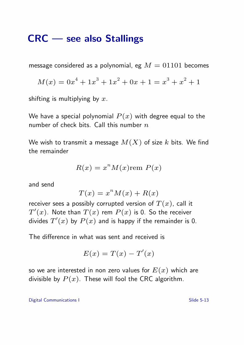
message considered as a polynomial, eg M = 01101 becomes
M(x) = 0x4 + 1x3 + 1x2 + 0x + 1 = x3 + x2 + 1
shifting is multiplying by x.
We have a special polynomial P (x) with degree equal to thenumber of check bits. Call this number n
We wish to transmit a message M(X) of size k bits. We findthe remainder
R(x) = xnM(x)rem P (x)
and sendT (x) = xnM(x) + R(x)
receiver sees a possibly corrupted version of T (x), call itT $(x). Note than T (x) rem P (x) is 0. So the receiverdivides T $(x) by P (x) and is happy if the remainder is 0.
The di!erence in what was sent and received is
E(x) = T (x) ! T $(x)
so we are interested in non zero values for E(x) which aredivisible by P (x). These will fool the CRC algorithm.
Digital Communications I Slide 5-13

CRC Properties
➤ If P (x) has both first and last terms nonzero it will notdivide a poly of the form E(x) = xi. Such a CRC willthus detect all single bit errors
➤ If P (x) has a prime factor with three terms it will notdivide a poly of the form E(x) = xi(1 + xj). Such aCRC will thus detect all double bit errors
➤ If P (x) also has a factor (x + 1) it will not divide anE(x) poly with an odd number of terms.
➤ won’t divide a E(x) of the form xiB(x) where B(x) hasits last term equal to one if B(x) has order less than n.(burst errors)
Digital Communications I Slide 5-14

CRC Realisation
P (x) = x5 + x4 + x2 + 1
adding modulo 2 is exclusive or; multiplying by x is shifting.
+ + +x x x x 14 3 2 M(x),
high bits first
➤ each shift is like a step in long division
➤ if the x4 bit is set, then when it is shifted out it causesx4 + x2 + 1 to be subtracted as next bit of M(x) isshifted in
➤ note leading zeroes in M(x) are unhelpful!
➤ moderately painful in software
Digital Communications I Slide 5-15
CRC Realisation Example
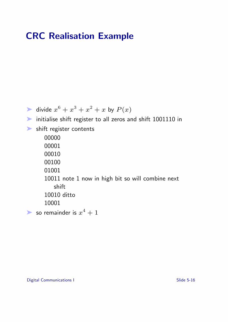
➤ divide x6 + x3 + x2 + x by P (x)
➤ initialise shift register to all zeros and shift 1001110 in
➤ shift register contents
000000000100010001000100110011 note 1 now in high bit so will combine next
shift10010 ditto10001
➤ so remainder is x4 + 1
Digital Communications I Slide 5-16
Compression
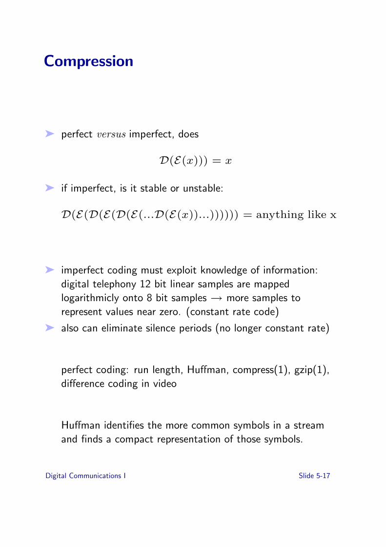
➤ perfect versus imperfect, does
D(E(x))) = x
➤ if imperfect, is it stable or unstable:
D(E(D(E(D(E(...D(E(x))...)))))) = anything like x
➤ imperfect coding must exploit knowledge of information:digital telephony 12 bit linear samples are mappedlogarithmicly onto 8 bit samples " more samples torepresent values near zero. (constant rate code)
➤ also can eliminate silence periods (no longer constant rate)
perfect coding: run length, Hu!man, compress(1), gzip(1),di!erence coding in video
Hu!man identifies the more common symbols in a streamand finds a compact representation of those symbols.
Digital Communications I Slide 5-17

Video Compression
➤ try to eliminate redundancy, code more e"ciently
➤ eg if image doesn’t change between frames, don’t send
➤ transform image to find frequency content
➤ gore: transform coding works on 8 by 8 pixel tiles,requantizes at course resolution and then gets rid offrequencies with zero content
➤ eg tile all the same colour only has one frequencycomponent
➤ eg JPEG (joint photographic experts group) uses thismethod to compress single images
➤ motion JPEG uses JPEG on successive frames, it onlylooks at one frame at a time (intraframe coding)
➤ MPEG does this and more
➤ MPEG-1 1.5 Mbps (CD-ROM speeds)➤ MPEG-2 15 Mbps (compressed HDTV)➤ MPEG-4 ?? (very high level descriptions)
Digital Communications I Slide 5-18

MPEG - basics
➤ take advantage of similarity between successive frames, ieinterframe coding (sounds simple)
➤ including predicting bits of the picture moving about(sounds complicated)
➤ di!erent frames:
➤ I-frames (intraframe) which are just like JPEG (closeenough)
➤ P-frames (predictor) tiles are coded as being a tile froma previous frame but moved (and some di!erenceinformation)
➤ B-frames (bidirection interpolated) average of tiles(with motion) from previous and future frames
➤ I-frame every 8 frames: I 2B P 2B P 2B I
➤ can vary quality and get same coded data rate
➤ can keep quality constant and get variable data rate
➤ nasty to encode, not too bad to decode
Digital Communications I Slide 5-19

Encryption
➤ well known E and D functions which take an extraargument which is the key
➤ encoding is called encryption, decoding decryption.
➤ moving keys around is interesting (but nothing to do withcoding)
➤ may be interested in only certain people being able todecrypt (in which case the decryption key should be secret)or certain people being able to encrypt (encryption keysecret) or both
Digital Communications I Slide 5-20

Symmetric Key Cryptosystems
decryptencrypt
plaintext plaintext
ciphertext
key key
ciphertext = Encrypt(plaintext, key)
plaintext = Decrypt(ciphertext, key)
symmetric — both sender and receiver know the same secretkey
Digital Communications I Slide 5-21

Using Symmetric Secret Keys
➤ Authentication
➤ Ann " Bob: Challenge➤ Bob " Ann: Encrypt(Challenge, Key)
➤ Integrity
➤ Ann " Bob: Message, Encrypt(F(Message), Key)
➤ Confidentiality
➤ Ann " Bob: Encrypt(Message, Key)
Digital Communications I Slide 5-22

Other forms of Coding
➤ coding to aid modulation eg 4B5B or scrambling
➤ application level coding — negotiation about coding
➤ framing, bit stu"ng, “code violations”
Digital Communications I Slide 5-23

Grand Example
A/D
12->8
encrypt
FEC 64->72
mod
D/A
8->12
decrypt
FEC 72->64
demod
4 KHz speech
12 bits per 125 us
8 bits per 125 us (64 Kbps)
insecure 64 Kbps
high error rate, 72 Kbps
analog
Digital Communications I Slide 5-24

Exercises
5-1 List 5 types of coding you encounter everyday, indicate thecommunications channel, the type of information beingencoded, the type of coding taking place, and the type of(now coded) information carried by the communicationschannel
5-2 Why are CDs recorded at a sampling rate of 44.1kHz ?
5-3 Serial data is used to represent 8 data-bits, however only 7bits are needed to represent the common ASCII data set(the data representing common punctuation, A-Z, a-z, 0-9and so on). As a result serial data can use the eight bit todetect errors, this error detection is called parity. Parity canbe described as None which means it is unused, Odd whichmeans that the parity data bit is changed so that the sumof all 8 data bits is an odd number. Eg. data: 0100101would get a parity of 0, while data: 1100000 would get aparity of 1. The final type of parity is Even which like Oddchanges the value of the parity data bit, so that the sum ofall 8 data bits is an even number. E.g. data: 1110001 willget parity 0, while data: 0000001 gets parity 1.
An example of an N,K block code (N=7 and K=8), showhow a lookup table may be used to implement Odd parity.
5-4 Compression
(i ) Compare Lossy and Lossless compression(ii ) Compare Temporal and Spatial Compression(iii ) Explain why lossy compression is commonly used
Digital Communications I Slide 5-25

for Audio and Video (e.g. mp3 audio, MPEG video, andused in Digital TV)
5-5 Encryption
(i ) Describe how an encryption mechanism can be usedto verify a stranger can be trusted.(ii ) Describe how an encryption mechanism can beused to verify an email from a friend.(iii ) Describe how an encryption mechanism can beused to allow two friends to safely share a secret.
Digital Communications I Slide 5-26

Topic 6: Multiplexing
Previous topic
➤ Coding
➤ Digitization and Sampling
➤ Error Detection and Correction
➤ Block Codes➤ Information Theory➤ Compression➤ Encryption
Overview of this topic
➤ Multiplexing
➤ Common-Place Example
➤ Time Division Multiplexing
➤ Local Area Network Example
➤ Shared vs. Non Shared Media
Digital Communications I Slide 6-1

Multiplexing
DemultipexingMultiplexing
Lower channel
➤ multiplexing is about how a channel is shared out
➤ can view it as producing a number of higher layer channelsfrom a lower layer channel
➤ coding is required to distinguish the higher layer channelsfrom one another
➤ policy is required to determine who uses what part (space,time, frequency, etc) of the lower layer channel
Digital Communications I Slide 6-2
A Familiar Example
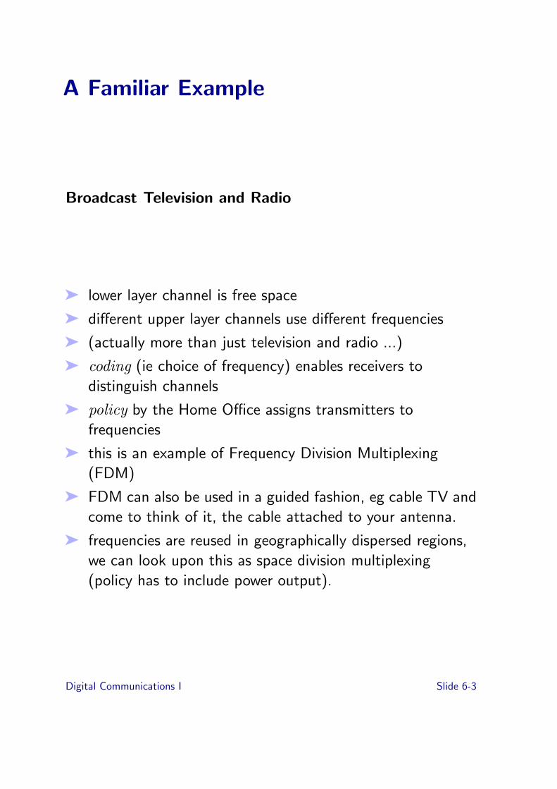
Broadcast Television and Radio
➤ lower layer channel is free space
➤ di!erent upper layer channels use di!erent frequencies
➤ (actually more than just television and radio ...)
➤ coding (ie choice of frequency) enables receivers todistinguish channels
➤ policy by the Home O"ce assigns transmitters tofrequencies
➤ this is an example of Frequency Division Multiplexing(FDM)
➤ FDM can also be used in a guided fashion, eg cable TV andcome to think of it, the cable attached to your antenna.
➤ frequencies are reused in geographically dispersed regions,we can look upon this as space division multiplexing(policy has to include power output).
Digital Communications I Slide 6-3

FDM
(Frequency division multiplexing)
➤ based on orthogonality of sinusoids
➤ wave division multiplexing uses di!erent wavelengths oflight in fibre optics (di!erent lasers for transmission,defraction gratings at receiver to separate out)
➤ tend to think of turning light on and o!, but this is stillmodulation of the carrier
➤ WDM (wave division multiplexing), commonly used bytelecommunications companies, is just FDM with higherfrequencies
Digital Communications I Slide 6-4

Time Division Multiplexing
➤ transmit di!erent channels at di!erent times
➤ think of television programmes on the same televisionchannel
➤ television channel is lower layer channel
➤ series of episodes of Neighbours is a higher layer channel(for some value of higher)
➤ receivers discriminate by content or looking at theschedule; coding is by positioning in time.
➤ policy by programme controller.
➤ note orthogonality by non overlapping time
➤ grain of multiplexing is length of continuous time forwhich higher layer channel occupies lower layer channel, ieon TV around 30 minutes, but variable.
Digital Communications I Slide 6-5

Synchronous Time Division Multiplexing
➤ in synchronous time division multiplexing the times atwhich a higher layer channel uses the lower channel arestrictly periodic. receiver can tell where the higher layerchannels are by looking in time; the symbols in the channeldo not have to contain identification
➤ best example is digital telephony
frame time (125 us)
slot time (3.9 us)
time
0 40 1 2 34321
8 bits
31
➤ synchronous multiplexing provides for constant bandwidth,constant delay channels (just like FDM does, just likephysical channel does)
➤ call a constant bandwidth, constant delay channel a circuit
➤ some people say “real” circuit to distinguish from virtualcircuits
➤ circuits are great for carrying constant rate information
Digital Communications I Slide 6-6

Asynchronous Time Division Multiplexing
124 3 4
➤ appropriate when demands from higher layer channels arevaried
➤ if we have 100 workstations each of which occasionallyrequires 5 Mbps but average 100 Kbps we can give themeach 5 Mbps circuits, or we can give them 10 Mbps toshare.
➤ statistical multiplexing hoping that peak demands fromdi!erent higher layer channels do not occur at the sametime.
➤ three immediate consequences:
➤ symbols in the channel must be grouped into packets➤ packets must contain labels identifying them➤ possibility of contention; some policy is required to
resolve this
➤ labels are addressing information
Digital Communications I Slide 6-7

Async (cont’d)
➤ policies for dealing with contention are varied
➤ on point to point links, or within an end system (host)these policies are implemented by the multiplexing entity.
➤ in the case of shared media access these policies areimplemented in a distributed fashion (most of what isabout to follow)
➤ contention means channels are not fixed delay and are notfixed capacity.
➤ packet switching
➤ rate adaption
Digital Communications I Slide 6-8
Random Access
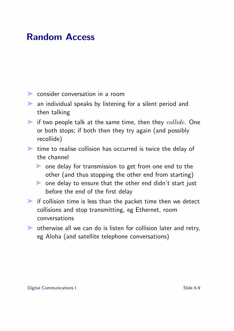
➤ consider conversation in a room
➤ an individual speaks by listening for a silent period andthen talking
➤ if two people talk at the same time, then they collide. Oneor both stops; if both then they try again (and possiblyrecollide)
➤ time to realise collision has occurred is twice the delay ofthe channel
➤ one delay for transmission to get from one end to theother (and thus stopping the other end from starting)
➤ one delay to ensure that the other end didn’t start justbefore the end of the first delay
➤ if collision time is less than the packet time then we detectcollisions and stop transmitting, eg Ethernet, roomconversations
➤ otherwise all we can do is listen for collision later and retry,eg Aloha (and satellite telephone conversations)
Digital Communications I Slide 6-9

Random Access - continued
➤ some collisions are nondestructive, eg Hubnet, COPEwireless XOR in the Air
➤ advantages:
➤ control is simple and distributed, very fault tolerant➤ access to channel is quick when lightly loaded
➤ disadvantages:
➤ access to channel is not bounded under high loads➤ although potentially “fair” no easy way exists to skew
fairness according to need
Digital Communications I Slide 6-10

Token Passing
➤ transmitter must have token in order to transmit
➤ when through, token is passed along
➤ eg in a two way radio conversation “over”
➤ usually in a ring (either physical or logical) to ease decisionof to whom to pass token
➤ problems with
➤ token disappearing➤ tokens getting duplicated
➤ examples: token ring, FDDI, token bus
Digital Communications I Slide 6-11

Reservation Systems
➤ reserve time in advance
➤ synchronous TDM is an example (everyone knows whichreservation belongs to who)
➤ in general, transmitters need only know their reservations
➤ useful when delays are large (eg satellites)
➤ still need a channel for reservation requests which hassome other mechanism (such as random)
Digital Communications I Slide 6-12

Slotted Systems
➤ channel is divided into fixed sized slots (just like insynchronous TDM)
➤ access to the slots is asynchronous ie transmitters contendfor them in a statistically multiplexed fashion
1234 4 3 3 3 3 33 4 44 12
➤ di!erent schemes for access are possible:
➤ slots are marked free or busy, a transmitter seeing anempty slot may fill it
➤ may be a limit on how many slots a transmitter may useat one time
➤ this limit may be adjustable (possibly by reservation)➤ possible to run a synchronous service by periodic
allocation
Digital Communications I Slide 6-13

Slotted Systems
➤ since access is asynchronous, requires addressinginformation inside
➤ fine, fixed grain of multiplexing, easier to make guaranteesabout delay in getting to channel
➤ examples: Cambridge rings, DQDB, ATM
➤ slots sometimes called cells
➤ inbetween circuits and variable sized packets
Digital Communications I Slide 6-14
Shared Media Multiplexing
Shared Media Multiplexing in Local Area Networks
➤ distances are short
➤ transmission costs are low
➤ “customer” and provider are usually same organisation
➤ communications not tari!ed by use, expense is primarilyattachment cost and administration
➤ usually no roads to dig up
➤ “customers” have a co-operative relationship (aided bysystem administrators ...)
Digital Communications I Slide 6-15

Shared versus Non Shared Media
➤ “shared media” implies that the capacity of the network isfixed and is shared (in some fashion) by the attacheddevices.
➤ as network grows, the capacity remains fixed (links may beadded, but all tra"c traverses all links)
➤ “shared media” may mean a shared physical channel (as inEthernet) or a sharing just above the physical level (egtoken ring)
➤ shared media networks have simple if not trivial routingstrategies
➤ topologies like buses, rings, some tree networks
➤ requires an element of trust, devices can interfere withcommunication of others
➤ failure of a link or the single shared physical link can causecomplete network failure, often di"cult to add inredundancy
➤ simple — most local area networks prior to 1990 built thisway
Digital Communications I Slide 6-16

Shared versus Non Shared Media cont.
➤ non shared — links are added as network grows; networkcapacity grows (like the telephone network)
➤ ability to damage other communication is limited
➤ topologies are more general, ie graphs
➤ routing decisions are harder
➤ possible to include redundant links
➤ not so simple but now the way most local area networksare done
Digital Communications I Slide 6-17

Shared Media LANs: Ethernet
➤ Carrier Sense Multiple Access / Collision Detect(CSMA/CD)
➤ carrier sense — listen before talking
➤ collision detect — listen after talking to see if you’re theonly one
➤ collision window is twice the cable length
➤ retransmission strategy tries to lighten up when thenetwork is busy
➤ more collisions, longer delay between retransmissions:
➤ when collision is detected, jam the media to ensureeveryone realises there has been a collision
➤ backo! a random time (uniformly distributed to somemax) before retransmission attempt
➤ keep doubling the max until reaching a limit of retries
➤ Less common in copper, but wireless (802.11 WiFi) hasbecome the new copper.
Digital Communications I Slide 6-18

Ethernet Continued
➤ minimum ethernet packet size is the collision windowlength
➤ cable interconnected by repeater is still a single collisiondomain
➤ bridges and routers isolate collisions
➤ as speed and distance goes up, minimum packet size goesup accordingly
➤ e"ciency is also related to collision window: when collisionoccurs a collision window’s time is consumed. If this iscomparable to average packet size then there is impact; Ifpackets are much larger then impact is smaller
➤ throughput depends upon distribution of o!erred load: asingle device trying to send at 10 Mbps on a 10 MbpsEthernet can; 100 devices trying to send 100 Kbps eachcan’t.
➤ Ethernet strengths are simplicity, passive cable
➤ relies on relatively low loading (eg 20% is shaky)
➤ 10Mbps is the common one (and the IEEE 802.3 standard)
➤ shared physical channel is slightly problematic — everyoneis trying to send on the same cable they are listening to
➤ no guarantee of when a station gets access
Digital Communications I Slide 6-19

Token Ring
➤ stations arranged in a physical ring of unidirectional links.Each link is a point to point link
➤ multiplexing is based on owning the token
➤ frames are delimited by code violations: patterns whichviolate the modulation scheme
➤ frame format is eitherstart delim access control end delim
for a token or
start delim access control FC DA SA INFO FCS end delim
for a frame with some information in it.
FC = frame control (boring)DA,SA addressesFCS covers from FC to INFOFS = frame status — receiver can mark as havingrecognised address
➤ access control contains token information
➤ a station wishing to transmit must wait for a free tokenand change it into a frame
➤ frame may be bigger than entire ring, snakes around pastdestination and returns to sender who takes it o! the ringand releases a new free token
➤ tokens can have priority which can be modified (even busytokens) by stations having higher priority information
Digital Communications I Slide 6-20
Token Ring cont’d
➤ no collisions, system throughput very high almostirrespective of demand distribution (in fact better wheneveryone wants to send)
➤ latency guarantee (in the non priority case) is max packetsize time number of stations (ie big)
Token Management
➤ monitor station required to ensure one and only one tokenexists
➤ each station is capable of being a monitor station
➤ monitor sends out special tokens occasionally saying “I amthe monitor”
➤ if a station doesn’t see one of these it enters a “claimmonitor” state
➤ stations contend to be monitors, highest address wins
➤ first token rings developed in the 60’s
➤ 802 token ring based on IBM design of 1980 (4 Mbps)
➤ FDDI token ring at 100 Mbps
Digital Communications I Slide 6-21

Slotted Rings
➤ ring is divided into fixed sized slots
➤ each slot has a bit (like a token) which can be set to full orempty
➤ stations wishing to transmit wait for an empty slot andmark it full, placing addressing information and data intothe slot
➤ a full slot rotates around the ring to destination where it isrecognised and either marked empty or marked to indicateit has been received (or not)
➤ if not destination delete, then slot continues around tosource which extracts it from ring
Digital Communications I Slide 6-22

Slotted Rings cont.
➤ to prevent endlessly circulating full slots a monitor is used
➤ when a slot is filled its monitor bit is cleared➤ monitor sets monitor bits in all full slots➤ if it sees a full slot with a monitor bit set it sets the slot
to empty➤ similar problems to token ring in terms of who is
monitor➤ maintaining slot structure is arguably easier than token
management
➤ latency guarantees are relatively good (ie if source deleteand always pass empty slot on) because units are fixed size
➤ small items slip in the middle of big items (fine grainsharing)
➤ Cambridge ring
➤ Cambridge Fast Ring
➤ Cambridge Backbone ring
➤ Orwell ring (destination delete) (British Telecom)
➤ no huge commercial successes (just ahead of their time)
➤ also, like any new system not quite as easy to set up (asEthernet)
Digital Communications I Slide 6-23

Shared Media Conclusions
➤ dominant technologies are ethernet (and variants)
➤ comparison of performance in Stallings, but misses theimportant point: these things rely on low utilisation
➤ token bus for the brave
➤ 100 Mbps, 1, 10 Gbps Ethernet (but not really used asshared media)
➤ non shared media local networks are now the norm
➤ Why did “Ethernet”, arguably the least appropriate sharedmedia network for high speeds win?
Digital Communications I Slide 6-24

Centralised Multiplexing
➤ When you have all the information in one place, should beable to do better
➤ In particular, no latency between transmissions.
➤ Priority versus share (general scheduling issue).
Audio
Video
LatencyInsensitiveData
Scheduler
Digital Communications I Slide 6-25
Scheduling Issues
➤ Priority is a good mechanism but often not a good policy
➤ “Fairness” is not a well defined concept.
➤ Allocating notional shares, eg weighted round robin is analternative to strict priority
➤ So is policing within a priority class
➤ Care if layered multiplexing!
Digital Communications I Slide 6-26

NonOrthogonal Multiplexing
➤ FDM, TDM are orthogonal in the sense that any giventotal channel signal can be divided into its basis functioncomponents uniquely.
➤ possible to find functions which are nearly orthogonal
➤ with too many get interference
➤ with a few get a little bit of interference, run errorcorrecting code on top to compensate
➤ reduce need for co-ordination with other transmitters aslong as transmitter and receiver know what is going on
➤ eg frequency hopping spread spectrum
➤ eg direct sequence spread spectrum (Code DivisionMultiplexing, Code Division Multiple Access)
Digital Communications I Slide 6-27

CDMA
➤ Each channel is assigned a code which is a pseudo randomsequence.
➤ The code is cycled through at a high rate, typically oncethrough the entire code sequence for each data bit we wishto transfer. We sometimes call each bit of the code a chipto distinguish them from the data bits.
➤ transmitter exclusive ORs the chips with the databits andtransmits the produced transmit chip sequence.
➤ receiver exclusive ORs same pseudo random sequence withthe received chips and looks for big correlations to obtainchip sync.
➤ some chips get clobbered in the channel but statisticallymajority voting works
Digital Communications I Slide 6-28

CDMA for mobile telephony
➤ Codes do not need to change during hando!. Couldimagine very long lived codes.
➤ Silence suppressed voice transmission gives immediatebenefits. (Your transmission is noise to everyone else.)Claim is a voice channel is only 35% active. (But need tobe careful about code sync — don’t want to chop-o! thefront of every word)
➤ Soft capacity, can increase capacity if willing to degradethe component channels.
➤ Single frequency channel (all processing is digital)
➤ Some security (need to know the code)
Digital Communications I Slide 6-29

Multiplexing and Channel Characteristics
➤ synchronous multiplexing gives fixed delay, fixed capacitycircuits
➤ asynchronous multiplexing doesn’t
➤ the contention policy in asynchronous multiplexing directlyimpacts the channel characteristic: how much variability incapacity, delay
➤ relation to scheduling (packets run to completion, slotstime sliced, synch strict periodic scheduling)
➤ think of requirements for traditional data, continuousmedia and interactive continuous media
➤ distinguish latency from variance in latency
Digital Communications I Slide 6-30

Layered Multiplexing
➤ asynch on top of sync
➤ sync on sync
➤ async on async
➤ eg an Ethernet interface may be only concerned withwhether Ethernet packets are for it; not which process inthe workstation they are for
➤ which process is done by a higher layer entity in theworkstation
➤ each point of multiplexing is a point of contention,opportunity for more interference to creep in.
Digital Communications I Slide 6-31

What is Switching?
multiplexingdemultiplexing
routing andconcatenation
➤ need a way of recognizing the higher layer channels on thelink
➤ need to figure out where they should go and get them there
➤ need to stu! them down links along with other higher layerchannels.
Digital Communications I Slide 6-32
Circuit Switching
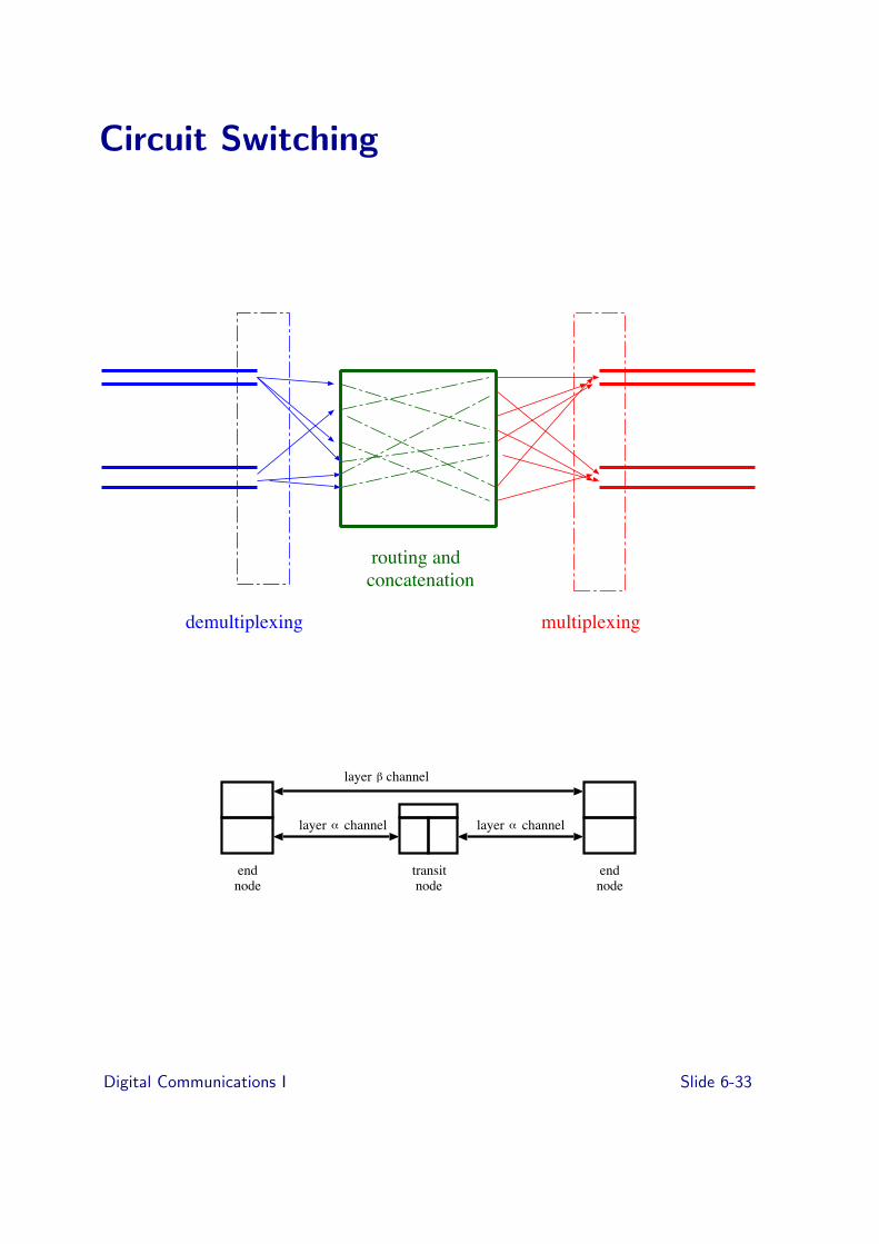
multiplexingdemultiplexing
routing andconcatenation
transit node
endnode
endnode
layer layer
channellayer
channel channelα
β
α
Digital Communications I Slide 6-33

Packet Switching
multiplexingdemultiplexing
routing andconcatenation
transit node
endnode
endnode
layer layer
channellayer
channel channelα
β
α
Digital Communications I Slide 6-34

WDM Switching
multiplexingdemultiplexing
routing andconcatenation
transit node
endnode
endnode
layer layer
channellayer
channel channelα
β
α
Notice a theme here?
These will last three pages will not make sense unless youcame to lectures.
Digital Communications I Slide 6-35

Exercises
➤ [6-1]
DemultipexingMultiplexing
Lower channel
A B A’ B’
X X’
➤ [6-1] In the diagram above, how does the receiving entityX’ distinguish data destined for A’ from data destined forB’?
➤ [6-2] For the commercial television system we haveexamples of multiplexing in the spatial, temporal (time),and frequency domains. Briefly describe, using thetelevision system as an example, what is meant by thesethree forms of multiplexing.
➤ [6-3] Why is synchronous time-division multiplexingcommonly used in telephone systems?
➤ [6-4] Synchronous Time Division is popular for thedeployment of fixed bandwidth services called circuits,sometimes also called virtual circuits. A virtual circuitprovides an end user with the equivalent of a fixeddedicated link between two points. What properties makesuch a service possible?
➤ [6-5] Asynchronous Time Division requires the use oflabels, why doesn’t Synchronous Time Division?
➤ [6-6] Often Asynchronous Time Division limits the length
Digital Communications I Slide 6-36

of packets — no one has an infinite amount of bu!er spacefor the incoming packet — despite this, starvation is stillpossible. Explain why this may occur?
➤ [6-7] Random Access mechanisms have been common forcontrolling (or not controlling) access for AsynchronousTime Division systems. List properties that would makeRandom Access more-fair.
➤ [6-8] Describe one condition under which the performanceof a well-behaved Random Access mechanism will degrade.
➤ [6-9] Describe what is meant by CSMA; how does the CDof CSMA/CD improve things?
➤ [6-10] Old-style (10Mbps) Ethernet is an example of aShared-Media LAN, what is another example?
➤ [6-11] New-style (10Gbps) Ethernet is an example of anon-Shared Media LAN. Compare Shared and non-SharedLANs, noting what it is thats shared, drawing a typicaltopology for each and point out where a critical equipmentfailure might occur.
➤ [6-12] Centralizing Multiplexing is a great way ofcontrolling/sharing access to a common resource — suchas a shared media. Considering the physical properties ofWiFi, why would this idea degrade rather than improveperformance?
Digital Communications I Slide 6-37

Topic 7: Protocol/State
Previous topic
➤ Multiplexing
➤ Common-Place Example
➤ Time Division Multiplexing
➤ Local Area Network Example
➤ Shared vs. Non Shared Media
Overview of this topic
➤ Error Control Protocol
➤ Performance
➤ State Diagram
➤ Continuous ARQ
➤ Flow Control
Digital Communications I Slide 7-1

Protocols and State
channel
errors, loss
• a protocol is set of procedures and formats that entities useto communicate information.
• as always, di!erent people mean di!erent things when theyuse the term: is a coding scheme a protocol?
• here we are particularly concerned with protocols involvingstate changes within entities: indeed often implementedand or specified as finite state machines
• communication protocols of this type are di"cult becauseone end only has an approximate model of the state of theother end (errors, loss from contention, delay variation)
• example of allies separated by mountains full of banditswishing to co-ordinate attack; never sure if messenger getsthrough.
• important example is an error control protocol (we’ll talkabout flow control too)
Digital Communications I Slide 7-2
Error Control Protocols
• strategy is to use an error detecting (rather thancorrecting) code and then retransmit when errors aredetected or data never received
• it is the receiver that knows whether an error has beenfound; it must request retransmission of data found to bein error
• called Automatic Repeat reQuest (ARQ)
• means delay in getting information through is variable evenif underlying channel is fixed delay
• see Halsall Chapter 4
• consider information transfer in one direction for clarity(although messages going in both directions)
Digital Communications I Slide 7-3
How it works: an example
• information is divided into frames
• each frame also contains a sequence number which rangesfrom 0...N ! 1, a field indicating that it is a DATA frameand a CRC:
DATA seq no information CRC
• when receiver sees a data frame with a correct CRC andwith a sequence number is was expecting, it sends anacknowledgement frame with the sequence number of thenext frame it is expecting:
ACK seq no CRC
• this allows transmitter to send next frame and to forget theprevious frame
• if it receives incorrect CRC or sequence number beyondwhat it was expecting it can send a NACK, saying whichsequence number it is expecting:
NACK seq no CRC
• what should receiver do if it receives a sequence numberfor a frame it has already acknowledged?
• what should transmitter do if it never receives an ACK?
• note sequence number eventually wraps round
Digital Communications I Slide 7-4

Performance of such a protocol
• frame size p bits, channel capacity b bits per second,channel delay d secs
• time to transmit frame is τtx = pb
• time to get frame down channel is d
• assuming acks and nacks are small and that no errors arefound, time from beginning transmission of one data frameto beginning of next is 2 # τd + p
b
• if τd is small, then throughput " b, if τd is large,throughput approaches p
2τd
propagation 2 # 108 m/s, p = 1000 bits
1 Kbps channeldistance τd tautx throughput
1 km 50 µs 1 s 1 Kbps200 km 1 ms 1 s 1 Kbps
5000 km 250 ms 1 s 670 bps
1 Mbps channel
distance τd tautx throughput
1 km 50 µs 1 ms 1 Mbps200 km 1 ms 1 ms 333 Kbps
5000 km 250 ms 1 ms 2 Kbps
Digital Communications I Slide 7-5

State Diagram
idle
data to send
timeoutreceive ACK
seq++ tx and wait
Transmitter
• transmitter must run time out and retransmit (why?)
• what makes a good time out period?
• ack must have correct sequence number
• note seq no is part of state
Digital Communications I Slide 7-6

idle
data with seq received
seq++ tx ack
data with wrong seq received
Receiver
Digital Communications I Slide 7-7

Continuous ARQ
• obvious improvement is to have multiple frames in transitat once with acknowledgements flowing back continuously
• think of a traction tread:
sender receiver
data frames not yet received
acks for previously received frames
• when everything is going like clockwork a received ackcauses a new data frame and a new received data framecauses a new ack
• the window is the number of frames (or bytes) that can bein transit unacknowledged (previous example was windowof 1 frame)
• if window is big enough then can keep link full
• better than just big frames — why?
• di!erent strategies when receiver detects a missing frame:
1. go back N:transmitter goes back to missing frame andrestarts from there possibly repeating correctly receivedframes
2. selective retransmission: transmitter only repeatsmissing frame, receiver acknowledges all correctlyreceived frames
• one simple, the other one more e"cient, which is betterrather depends on how often you expect to drop a frame
Digital Communications I Slide 7-8

Flow Control
• flow control is a general problem
• want to ensure that receiver can take in information at ratetransmitter is sending
• in circuit switching rate is the channel rate, everyone agrees
• packet switching allows rate adaption: transmitters don’thave to be at the same bitrate ...
• ... but must be a mechanism for balancing long terminformation rates
• example look on person’s face telling you they don’tunderstand
• example, X-on, X-o! flow controls:
“go until I tell you to stop”
receiver needs to be able to receive 2 channel delays worthof information after it issues the stop — why? " whathappens when channel delay is variable?
• window flow control — similar to our error controlprotocol, but performing a di!erent function
Digital Communications I Slide 7-9
Sliding Window
Sliding Window Error and Flow Control Protocol
• receiver tells transmitter what frames it has received andhow far ahead it is willing to receive
• receiver e!ectively opens and closes the window
• receiver does this on the basis of changing availability ofresources, in particular bu!ers
ACK rx seq no win size CRC
• transmitter’s model of receiver is now extended toresources (but is still potentially out of date)
Digital Communications I Slide 7-10

Other Generic Sorts of Protocol
• media access
• remote procedure call
• commitment concurrency and recovery protocols (not justcommunications!)
• Byzantine generals
Conclusions
• entity state in communication protocols try to model otherentity (and indeed the channel)
• this model is not always correct
• must cope with loss (and indeed disappearance of otherentities)
• time outs to cope with loss; means of poking one’s statemachine revising the model of the channel / other end
Digital Communications I Slide 7-11

Exercises
7-1 Identify three examples of ARQ (Automatic RepeatreQuest) you perform in everyday life (no computers)
7-2 Contrast Flow Control and end-to-end ARQ; considerparticularly what are the objectives of each, what are therequirements on the channel and what are the limitationson distance between the ends of the control.How much data is outstanding?How quick is recovery?The two approaches are interchangeable but each hasdisadvantages/advantages - give an example where each isappropriate.
7-3 Continuous ARQ can use a window: the number of frameswaiting for acknowledgment. Why is it better to use manysmall packets and a large window size than just increasethe size of the packet until it fills the link?
7-4 Consider packet loss in an ARQ link. Compare the numberof packets retransmitted if we use a basic ARQ, continuousARQ with go-back n, and continuous ARQ with selectivetransmission
7-5 Compare the end-system overheads (what resources arerequired) for each of the 3 ARQ schemes of the previousquestion.
Digital Communications I Slide 7-12

Topic 8: Naming Addressing Routing
Previous topic
➤ Error Control Protocol
➤ Performance
➤ State Diagram
➤ Continuous ARQ
➤ Flow Control
Overview of this topic
➤ Hierarchical vs. Non-hierarchical
➤ Class-based/classless routing
➤ Routing
➤ ARP
➤ Interconnect/Layers/Routing
➤ When do we route?
➤ Routing examples
Digital Communications I Slide 8-1

Naming, Addressing and Routing
One view:
➤ a name denotes something
➤ an address denotes where something is
➤ a route tells you how to get there
Example:
➤ name: Andrew Moore
➤ address: WGB FW16
➤ route: up one floor, go north then through the door turnright through next door...
Digital Communications I Slide 8-2

Another view
These are all just names (or identifiers)
➤ “names” identify things
➤ “addresses” are identifiers of attachment points (tonetworks)
➤ “routes” are identifiers of paths
Issue is one of binding. So its just like operating systems...
Name resolution, name lookup: binding a name to an address
Routing: binding an address to a route
Digital Communications I Slide 8-3

Addresses at multiple levels
➤ eg machine with name “frank.dcs.qmul.ac.uk” has138.37.88.242 for an IP address
00:0E:0C:5A:E6:9C for an “ethernet” address
serviceaccesspoint
➤ service access point is the point of attachment between anupper layer and lower layer entity.
➤ can view addresses as denoting service access points
➤ service access points can be long lived or shortlived, eg asession or a transaction
Digital Communications I Slide 8-4

Hierarchical versus Flat Address Space
➤ flat address has no structure
➤ only function as unique identifiers
➤ for example Ethernet 48 bit addresses
➤ can be moved around without modification
➤ logically centrally allocated
➤ hierarchical address spaces are divided up, usually to aidthe routing process
➤ our intuitive notion of address tends to be hierarchical
country network host
➤ IP (Internet Protocol) addresses are hierarchical four byteaddresses with variable sized boundaries. Old style (“Classbased”):
0 network
1 0
1 1 0
1 1 1 0
host(7 bits) (24 bits)
(14 bits) (16 bits)
(21 bits) (8 bits)
(28 bits)Multicast address
network
network
host
host
A
B
C
Digital Communications I Slide 8-5

➤ IP addresses usually quoted as decimal-represented-bytesseparated by “.”
➤ eg we have a class B network which is 10.37 (with top bitset becomes 138.37)
➤ Class A networks " who got them?
➤ Classless routing allows divisions on any boundary (how??)
➤ a network is free to put structure on the host field (andthere are standard things people do)
Digital Communications I Slide 8-6
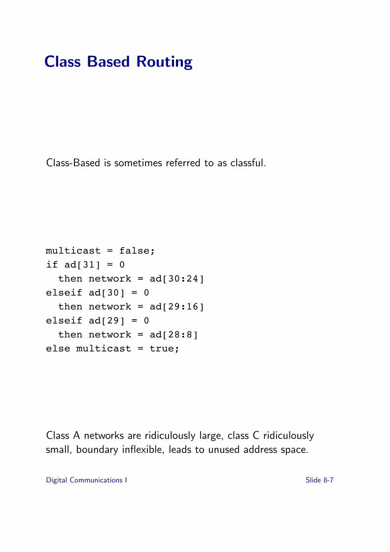
Class Based Routing
Class-Based is sometimes referred to as classful.
multicast = false;if ad[31] = 0then network = ad[30:24]
elseif ad[30] = 0then network = ad[29:16]
elseif ad[29] = 0then network = ad[28:8]
else multicast = true;
Class A networks are ridiculously large, class C ridiculouslysmall, boundary inflexible, leads to unused address space.
Digital Communications I Slide 8-7

Classless Routing
Classless is sometimes referred to as CIDR (pronounced“cider”): Classless Inter-Domain Routing.
➤ Store address space boundaries (network and mask) in allrouters.
➤ Not a big deal because had to store next hop for allnetworks, just adding a mask.
➤ Allows opportunity for aggregation: compaction of routingtables.
➤ Incentives for logical network number assignment
Digital Communications I Slide 8-8

Simple Example
Consider two networks 239.230.101.0 and 239.230.100.0.
Note that 239 is 11101111, so these would be class C old style.
New style, these would be 239.230.101.0/24 and239.230.100.0/24. (24 describes the mask which is 24 onesfollowed by 8 zeros, sometimes written as 255.255.255.0)
These networks could be aggragated as 239.230.100/23 eitherbecause they were the same network or because the routes tothem were in the same direction.
Even more flexibility by “longest matching prefix”.
Digital Communications I Slide 8-9

Routing
➤ act of binding addresses to path
➤ can view as binding higher layer channels to lower layerchannels (recall lower layer channel may not go all the way)
➤ routing may be
➤ static (ie fixed tables)➤ dynamic with network topology➤ dynamic with network condition (adaptive)
➤ it may be performed
➤ centrally➤ fully distributed
➤ simple example is binding an IP address to an Ethernetaddress using the Address Resolution Protocol (ARP)
Digital Communications I Slide 8-10
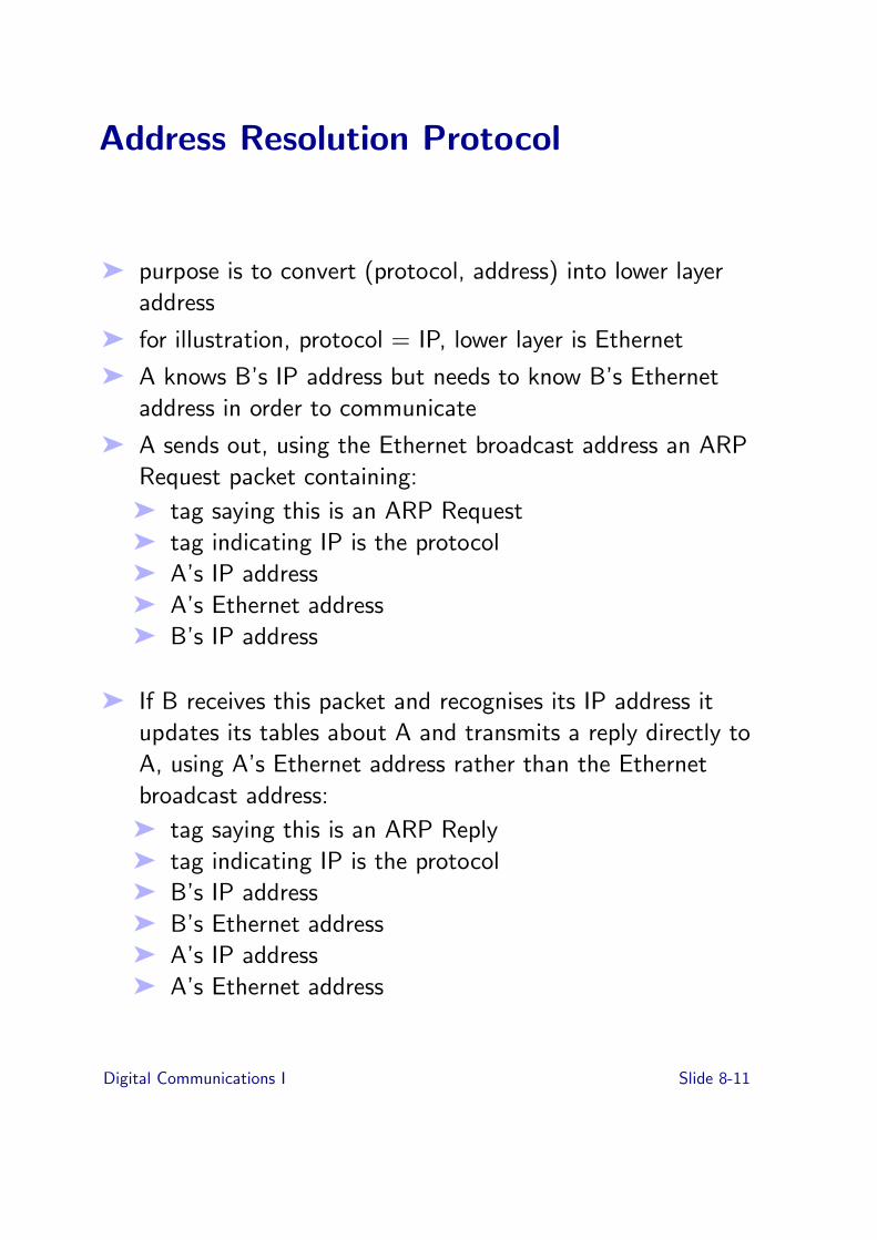
Address Resolution Protocol
➤ purpose is to convert (protocol, address) into lower layeraddress
➤ for illustration, protocol = IP, lower layer is Ethernet
➤ A knows B’s IP address but needs to know B’s Ethernetaddress in order to communicate
➤ A sends out, using the Ethernet broadcast address an ARPRequest packet containing:
➤ tag saying this is an ARP Request➤ tag indicating IP is the protocol➤ A’s IP address➤ A’s Ethernet address➤ B’s IP address
➤ If B receives this packet and recognises its IP address itupdates its tables about A and transmits a reply directly toA, using A’s Ethernet address rather than the Ethernetbroadcast address:
➤ tag saying this is an ARP Reply➤ tag indicating IP is the protocol➤ B’s IP address➤ B’s Ethernet address➤ A’s IP address➤ A’s Ethernet address
Digital Communications I Slide 8-11

Address Resolution Protocol cont.
➤ other people seeing ARP Requests update their tables (butgenerally don’t create new entries)
➤ nice property that rebooting host sending out a single ARPrequest will update all tables knowing about that host
Digital Communications I Slide 8-12

Interconnection Layers and Routing
Repeater, e.g., media converter
➤ repeater, just regenerates signal, “physical layer”interconnection, everything goes everywhere
physical layer
repeater
Digital Communications I Slide 8-13

Interconnection Layers and Routing (cont’d)
Bridge, e.g., ethernet switch
➤ bridge, has a set of addresses (eg Ethernet 48 bitaddresses) that it is willing to forward packets for “mediaaccess control” interconnection
don’t have to be the same media access controls on bothsides, just the similar concept of send this packet with this48 bit address in it
➤ simple things with potentially big tables
physical layer
MAC layer
MAC Layer Bridge
Digital Communications I Slide 8-14

Interconnection Layers and Routing (cont’d)
IP Router, e.g., your home firewall, more likely - bigboxes you never see that make the Internet go
➤ router, knows about structured network addresses andexploit structure to perform routing. Eg IP routers knowabout IP addresses
➤ need to understand network layer protocol
➤ may be several network layer protocols being used "multiprotocol routers
➤ may bridge when network layer protocol not understood
physical layer
MAC layer
IP Router
IP layer
Digital Communications I Slide 8-15

Routing in General Topology Networks
➤ network is represented by a graph with nodes and edges,edges have some cost associated with them. This cost mayvary in time.
➤ flood routing: incoming packets are repeated on all linksexcept the one on which the packet arrived. Packetscontain a hop count which is decremented at each node. Apacket with a hop count of zero is not repeated.
➤ if initial hop count is high enough, all non looping pathswill be tried (along with a few looping ones) " robust
➤ requires no knowledge of network topology➤ the shortest path will have been tried➤ burns network capacity
Digital Communications I Slide 8-16

Routing (cont’d)
➤ random routing: an incoming packet is sent out on somerandomly chosen link (unless it is addressed for that node).
➤ shortest path routing tries to find the path between twogiven nodes with the least cost, eg Dijkstra’s algorithm
➤ however, each node must build up a picture of the networkby exchanging information with other nodes, networktopology may be changing as links or nodes fail "inconsistent view of network
➤ inconsistencies may cause loops, as in A thinks the way toC is via B and B things the way to C is via A
➤ good analysis of distributed shortest path routingalgorithms in Schwartz
➤ routes may also be constrained, eg don’t go through thefollowing nodes..
➤ alternative to having the network decide how to routepackets is to have the sender decide (source routing):
➤ route is embedded in packet, just a list of hops along theway
➤ clearly can be made loop free➤ source needs to know network topology➤ source needs to know about changing conditions➤ loose source route is a list of some hops along the way
Digital Communications I Slide 8-17
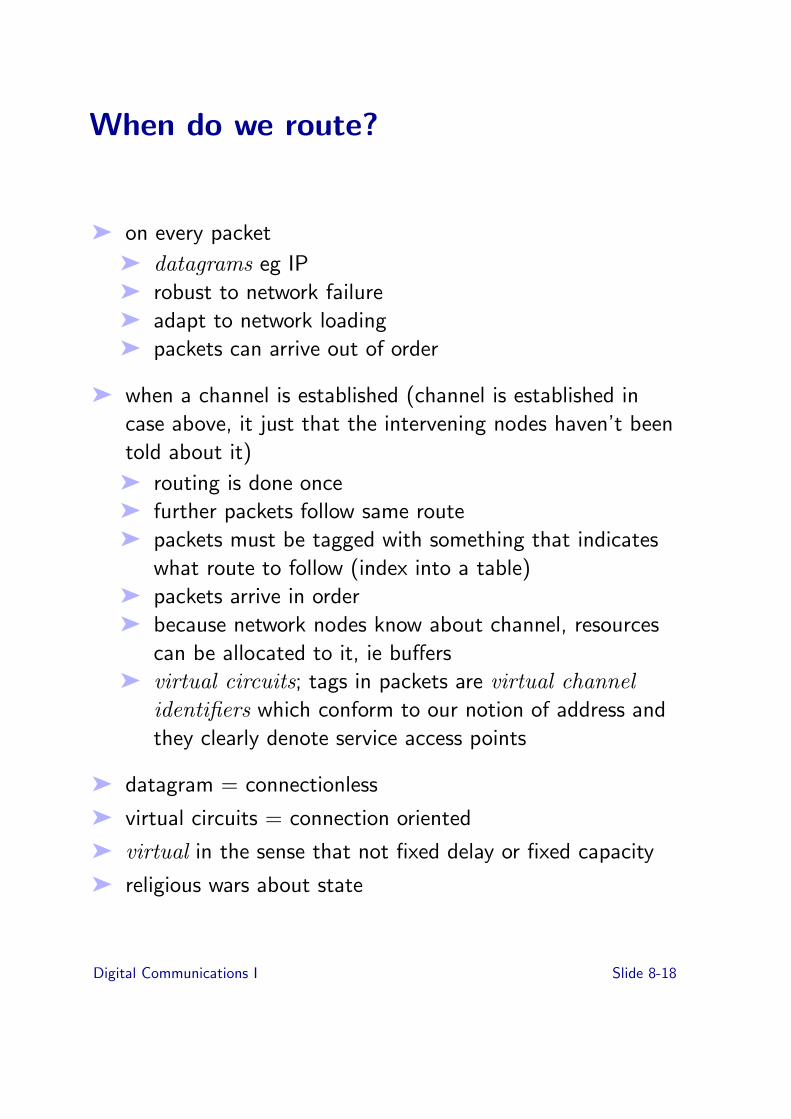
When do we route?
➤ on every packet
➤ datagrams eg IP➤ robust to network failure➤ adapt to network loading➤ packets can arrive out of order
➤ when a channel is established (channel is established incase above, it just that the intervening nodes haven’t beentold about it)
➤ routing is done once➤ further packets follow same route➤ packets must be tagged with something that indicates
what route to follow (index into a table)➤ packets arrive in order➤ because network nodes know about channel, resources
can be allocated to it, ie bu!ers➤ virtual circuits; tags in packets are virtual channel
identifiers which conform to our notion of address andthey clearly denote service access points
➤ datagram = connectionless
➤ virtual circuits = connection oriented
➤ virtual in the sense that not fixed delay or fixed capacity
➤ religious wars about state
Digital Communications I Slide 8-18

Routing and resource
➤ adaptive routing takes into account link utilisation (onevery packet or just when connection established, orsomething inbetween?)
➤ hot potato routing avoids contention on outgoing links (noneed for bu!ering if all tra"c is point to point and links allsame capacity)
Digital Communications I Slide 8-19

Exercises
➤ [8-1] Describe in terms of Names, Addresses and Routing,the binding processes as you look up a friends telephonenumber, select the part of the phone number that needs tobe dialed, dial, and are connected to your friend.
➤ [8-2] Consider accessing a web page on www.acm.org.Describe the address used at each layer from ethernet upto the location by the web-server on the machine. Considerthe IP layer, TCP, the possibility the web server is actuallymade up of several machines (www.acm.org is actuallyserved by a cluster of machines) and so on.
➤ [8-3] Give two examples of hierarchical addresses (not fromcomputing)
➤ [8-4] Give two examples of non-hierarchical addresses (notfrom computing)
➤ [8-5] Give two examples of partly-hierarchical addresses(not from computing)
➤ [8-6] Compute the number of A, B and C class addresses inthe Internet; who have the (old) A-class address spaces??
➤ [8-7] Consider the design of a trivial routing algorithm thatneeds to share information among a small number ofrouters on the network. What is the quantity of data youwill need to transfer between each router to keep tables upto date. Consider the network takes a given time t for eachlink to transfer data, estimate the propagation delay ofrouting updates across a network of routers. (The topology
Digital Communications I Slide 8-20

is arbitrary, however if you are not sure how to begin,consider a line of routers and a ring of routers). Drawsome conclusions on how intermediate summaries ofchange may a!ect things.Now consider what did you assume about the routingfunctions?Did all routers know about all destinations? (Is thatnecessary?)How might class-based routing assist you?
Digital Communications I Slide 8-21

Topic 9: The Internet
Previous topic
➤ Hierarchical vs. Non-hierarchical
➤ Class-based/classless routing
➤ Routing
➤ ARP
➤ Interconnect/Layers/Routing
➤ When do we route?
➤ Routing examples
Overview of this topic
➤ Internet Philosophy
➤ IP over Ethernet - an example
➤ Internetworking - the inter of internet
➤ IP Addresses and IP Routing
➤ Datagrams and Connections
➤ Next?
Digital Communications I Slide 9-1
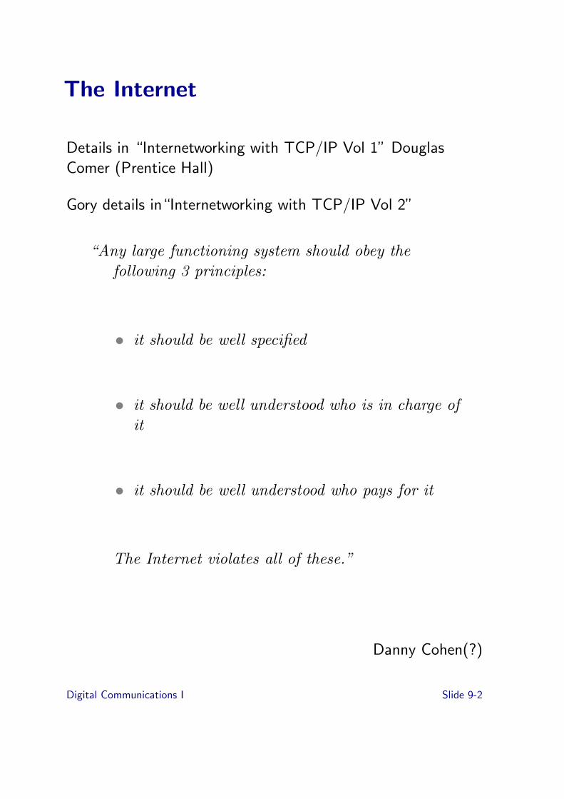
The Internet
Details in “Internetworking with TCP/IP Vol 1” DouglasComer (Prentice Hall)
Gory details in“Internetworking with TCP/IP Vol 2”
“Any large functioning system should obey thefollowing 3 principles:
• it should be well specified
• it should be well understood who is in charge ofit
• it should be well understood who pays for it
The Internet violates all of these.”
Danny Cohen(?)
Digital Communications I Slide 9-2
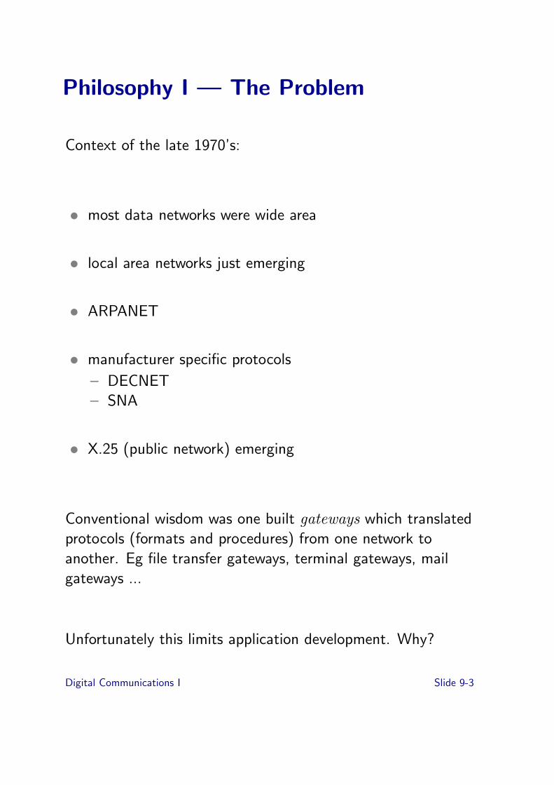
Philosophy I — The Problem
Context of the late 1970’s:
• most data networks were wide area
• local area networks just emerging
• ARPANET
• manufacturer specific protocols
– DECNET– SNA
• X.25 (public network) emerging
Conventional wisdom was one built gateways which translatedprotocols (formats and procedures) from one network toanother. Eg file transfer gateways, terminal gateways, mailgateways ...
Unfortunately this limits application development. Why?
Digital Communications I Slide 9-3
Philosophy II — The Solution
• use new protocols in all computers
– slow process but investment not huge in 1978!– give source and implementations away– largely research based, Unix based
• but can’t replace the networks
– define a lowest common denominator communicationservice which can be made to work on any network
– Internet Protocol (IP) service is the delivery of Internetdatagrams
– gateways now perform a simple task and are usually justcalled routers
– give source and implementations away
Digital Communications I Slide 9-4

IP Over Ethernet
Preamble 64 bits
Destination Addresss 48 bits
SourceAddress 48 bits
Packet Type16 bits
Frame Data368-12000 bits
CRC 32 bits
Ethernet Packet
IP Header IP Data
IP Datagram
Version HLen ServiceType Total Length
Identifier Flags Fragment Offset
Time to live Protocol Header Checksum
Source IP Address
Destination IP Address
Options (if any) Padding
Digital Communications I Slide 9-5

Internetworking
IP Router
Host
IP Router’s job is to forward IP packets towards thedestination by sending to the next hop which is on one of thenetworks to which it is attached.
• select which network to use
• selects which lower level address (eg Ethernet) to send to
• next hop may be the end or another router
• uses the IP destination address to determine this
Digital Communications I Slide 9-6

IP Addresses and IP Routing
• address has two parts: network address and host address.
• router examines network address to see if it is one of thenetworks to which it is attached. If so router sends to thehost on that network using the protocol for that network
• if not, router must decide which router to send it to
• essentially it has a table, called a routing table, whichcontains entries of the form
(IP network address, next router to use)
where the next router to use is on a network attached tothe current router
• can also have the notion of default router so that if youdon’t have a table entry for a particular IP network addressyou send to the default router which handles it.
Digital Communications I Slide 9-7

Routing Tables
• originally, some routing tables were maintained “by hand”,ie they were in a file that was editted by the local systemmanager
• now more dynamic, with provision for core system routers(which know how to get everywhere) and autonomoussubsystems which can control the routes into themselves
• adaption to link failure, and link load by routersexchanging information (Gateway-gateway protocols)
• arguably more work on routing done in the Internet than inany other network
Digital Communications I Slide 9-8

Connectionless versus Connection-Oriented
(deja vu again again)
Note:
datagram = connectionless
virtual circuit = connection oriented
Question:
What state is in an IP router?
Answer:
Routers know (something) about the state of the network.They know nothing about who is communicating with whom.
A datagram is a packet that can be routed to its destinationsolely on the basis of its contents.
Digital Communications I Slide 9-9

Transmission Control Protocol (TCP)
Context
• IP delivers packets between hosts across the globe
• routers know nothing about connections
• routers and links can become congested and lose packets
• bit errors can occur
• need something to provide reliable end to end delivery ofpackets
Host A Host B
Router
IP IP IP
NetworkInterface
NetworkInterface
NetworkInterface
Network 1 Network 2
TCP TCP
Application Application
NetworkInterface
Digital Communications I Slide 9-10

TCP Properties
1. stream oriented: a sequence of bytes
2. connection oriented: connection establishment (but thenetwork doesn’t know!)
3. reliable: recovers from errors or loss of packets bydetecting loss / error (how?) and retransmitting
4. full duplex: can send information in both directions
5. flow controlled: one end can tell the other end how farahead it can transmit (the window)
Data 5 Data 4 Data 3
Ack 0, W 6
Ack 1, W 7
Ack 2, W7
Host A Host B
• control and data information
• received data packets are acknowledged
• acknowledgement also indicates window size
• large window keeps network full of packets, higherthroughput
Digital Communications I Slide 9-11
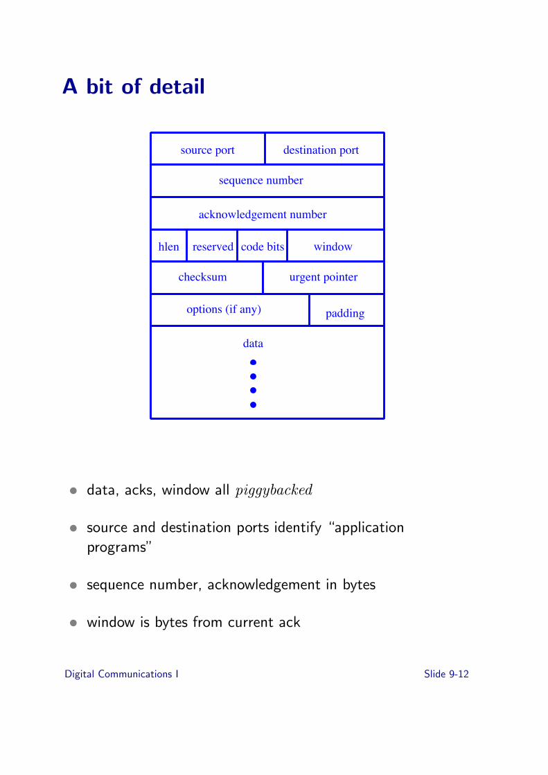
A bit of detail
source port destination port
sequence number
acknowledgement number
hlen reserved code bits window
checksum urgent pointer
options (if any) padding
data
• data, acks, window all piggybacked
• source and destination ports identify “applicationprograms”
• sequence number, acknowledgement in bytes
• window is bytes from current ack
Digital Communications I Slide 9-12

TCP: Back to modelling state....
• window size is a model of receiver resources
• acks provide a model of what receiver has received
• but need to model the channel as well:
– round trip time (why?)– variance in round trip time (why?)– capacity of the channel (why?)
• takes time to build up this model and only way in the vastmajority of implementations can determine capacity isthrough loss.
Digital Communications I Slide 9-13

User Datagram Protocol (UDP)
At same layer as TCP but provides a datagram service only.
Application
TCP UDP
Internet (IP)
Network Interface
• UDP also has port numbers
• used for simple queries, status
• used for SUN Remote Procedure Call (RPC)
Digital Communications I Slide 9-14

Application Protocols
Protocols using TCP:
• http
• telnet, rlogin, X
• file transfer protocol (ftp)
• network news transfer protocol (nntp)
• simple mail transfer protocol (smtp)
Protocols using UDP:
• echo
• time
• domain name server
• simple network management protocol (snmp)
• network file system (nfs)
Digital Communications I Slide 9-15

Evolution and Conclusions
• now clear dominant applications
• firewalls to prevent(?) unauthorised use, applications
• firewalls are of course application level gateways....
• application innovation only over http???
Digital Communications I Slide 9-16

Why Success?
• independence of vendors?
• designed and driven by the users?
• evolution based on experience?
• openness?
• lowest common denominator makes it hard to move awayfrom?
• network had no view of services? (but now caching,Akamai...)
Digital Communications I Slide 9-17

Exercises
9-1 Illustrate the following two examples of encapsulation asused in the communications stack for: web tra"c onTCP/IP transported using Ethernet on wireless, and theNFS application over UDP/IP transported using Etherneton unshielded twisted pair (UTP) cable
9-2 A router separates two Ethernet networks.What two pieces of information are required by a computerto communicate with another connected on the sameEthernet network?What additional information is required by a computer onone Ethernet network to communicate with a computer onthe other side of the router?
9-3 It is said that the TCP protocol models the state of thecommunications path between the two ends of the TCPconnection.Why does it model the round trip time?Why does it model the variance in round trip time?Why does it model the capacity of the channel?
9-4 How does TCP build this model? Why does TCP need tobuild a new model every time?
9-5 Why would an Internet Router participate in thewindow-based flow control such as TCP?When would such participation be a disadvantage?
9-5 Why has the Internet Protocol(s) succeeded?
Digital Communications I Slide 9-18

Topic 10: Standards
Previous topic
➤ Internet Philosophy
➤ IP over Ethernet - an example
➤ Internetworking - the inter of internet
➤ IP Addresses and IP Routing
➤ Datagrams and Connections
➤ Next?
Overview of this topic
➤ ITU
➤ IEEE
➤ ISO
➤ IETF
Digital Communications I Slide 10-1

Standards
• not like a single manufacturer building a nut and bolt
• devices have to communicate with potentially lots ofdevices made by di!erent people.
• di"cult to standardise in light of experience (unlike nutsand bolts)
• note distinction between conformance and interoperability
Digital Communications I Slide 10-2

Standards Bodies - ITU
• worldwide telecommunications: InternationalTelecommunications Union (ITU), formerly known asCCITT
• part of the UN
• national representatives, but mainly telecommunicationoperators (eg BT, AT&T, ...) and manufacturers (egLucent, Alcatel, Marconi ...)
• di!erent series of “Recommendations”
• V series about digital communication over the public voicenetwork – modems!
• X series about packet communication over the digitalpublic network
• G series about low level transmission, modulation, framing
• Q series about signalling
Digital Communications I Slide 10-3

Standards Bodies - IEEE
• Institute of Electrical and Electronic Engineers
• standards for local area networks, the “802” committee
• eg 802.3 Ethernet, 802.5 token ring, 802.11 wavelan
• not all used
• 802.2 says what a frame is, talks about 48 bit addresses
Digital Communications I Slide 10-4
Standards Bodies - ISO
• International Standards Organisation (also UN)
• Open Systems Interconnection (OSI) programme
• layering model and 7 layered model
• a lot of standards which aren’t used, but some are
• often held up as a way not to create standards
Digital Communications I Slide 10-5

Standards Bodies IETF
• Internet Engineering Task Force
• interesting study in sociology
• standards are issued as RFCs (Request For Comment), butnow proceed through a drafting process
• original RFCs were actually requests for comment...
Digital Communications I Slide 10-6

Exercises
10-1 What is the vested interest of each of the ITU, IEEE, ISOand IETF?
10-2 Why did standards lead to an ATM cell size of 48-octets?
10-3 What makes a defacto standard? (e.g., Microsoft Word,Adobe Acrobat, Berkeley Unix, . . . )
Digital Communications I Slide 10-7