cylinder head, camshafts, upper and lower intake...
TRANSCRIPT
Cylinder Head, Camshafts, Upper and Lower Intake Manifolds
Removal & Installation
To Remove:
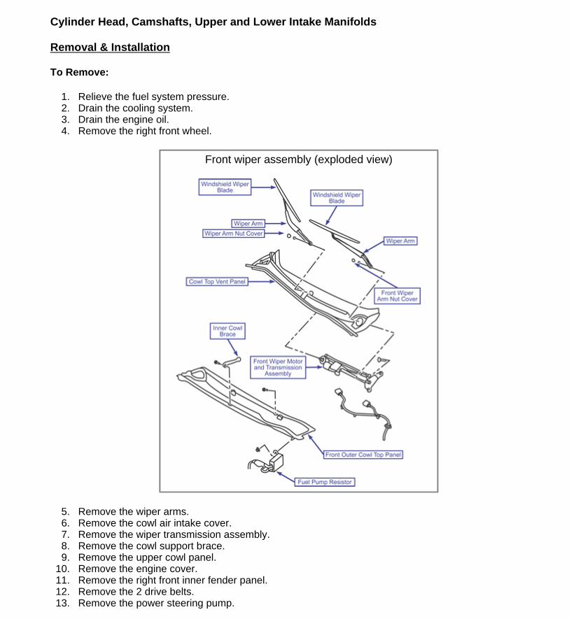
1. Relieve the fuel system pressure. 2. Drain the cooling system. 3. Drain the engine oil. 4. Remove the right front wheel.
5. Remove the wiper arms. 6. Remove the cowl air intake cover. 7. Remove the wiper transmission assembly. 8. Remove the cowl support brace. 9. Remove the upper cowl panel.
10. Remove the engine cover. 11. Remove the right front inner fender panel. 12. Remove the 2 drive belts. 13. Remove the power steering pump.
Front wiper assembly (exploded view)
Page 1 of 30Cylinder Head, Camshafts, Upper and Lower Intake Manifolds
5/12/2011http://arrc.epnet.com/autoapp/TOY_SIE_98-03_F3/TOY_SIE_98-03_Ch3_Cylinder_Head...

14. Remove the front exhaust pipe. 15. Remove the right engine mount bracket. 16. Remove the air cleaner cover. 17. Remove the air cleaner inlet and resonator. 18. Remove the air cleaner housing.
Exhaust system exploded view (3.0L)
Upper & lower intake manifold 3.0L exploded view
Page 2 of 30Cylinder Head, Camshafts, Upper and Lower Intake Manifolds
5/12/2011http://arrc.epnet.com/autoapp/TOY_SIE_98-03_F3/TOY_SIE_98-03_Ch3_Cylinder_Head...

19. Remove the upper intake manifold as follows: Disconnect the accelerator cable. Disconnect the throttle position sensor connector. Disconnect the IAC valve connector. Disconnect the 2 vacuum solenoid valve (VSV) connectors for the acoustic control induction system (ACIS). Disconnect the EVAP VSV connector. Remove the 2 nuts and disconnect the PS hose from the engine hanger bracket. Disconnect the PCV valve hose on the right cylinder head. Disconnect the ground strap and cable from the intake air control valve. Disconnect the ground cable from the upper intake manifold. Disconnect the brake booster vacuum hose from the upper intake manifold. Disconnect the 2 water bypass hoses from the throttle body. Disconnect the air assist hose from the throttle body. Disconnect the purge hose from the pipe on the emission control valve set. Disconnect the 2 ACIS vacuum hoses from the vacuum tank. Disconnect the engine harness retainer from the emission control valve set. Remove the 2 mounting bolts and the engine hanger bracket. Remove the 2 mounting bolts and the throttle body bracket. Remove the 2 bolts, 2 nuts and the upper intake manifold.
20. Remove the lower intake manifold as follows: Disconnect the 6 fuel injector harness connectors. Disconnect the fuel inlet hose from the fuel filter. Disconnect the heater hose from the intake manifold. Remove the 9 bolts, 2 nuts and washers. Remove the lower intake manifold with the fuel rail and injectors.
21. Disconnect the ECT sensor connector. 22. Disconnect the ECT gauge sender connector. 23. Disconnect the ground strap connector from the water outlet. 24. Disconnect the upper radiator hose from the water outlet.
Page 3 of 30Cylinder Head, Camshafts, Upper and Lower Intake Manifolds
5/12/2011http://arrc.epnet.com/autoapp/TOY_SIE_98-03_F3/TOY_SIE_98-03_Ch3_Cylinder_Head...

25. Disconnect the engine coolant reservoir hose from the water outlet. 26. Disconnect the water bypass hose from the water outlet. 27. Remove the 2 bolts, 2 nuts 2 washers and remove the water outlet. Remove and discard the
gaskets. 28. Remove the ignition coils. 29. Remove the spark plugs. 30. Remove the timing belt. 31. Remove the camshaft timing pulleys. 32. Remove the upper idler pulley. 33. Disconnect the 3 retainers and disconnect engine wire harness from the timing belt cover. 34. Remove the 6 mounting bolts and rear timing belt cover. 35. Remove the camshaft position sensors. 36. Remove the camshaft timing oil control valves. 37. Disconnect the wire harness shields from the cylinder heads. 38. Remove the 2 mounting bolts and remove the rear plate from the left cylinder head. 39. Remove the mounting bolt from the bracket and disconnect the inlet pipe from the water inlet.
Remove and discard the O-ring. 40. Remove the 3 mounting bolts and PS pump bracket from the right cylinder head. 41. Disconnect the bank 1 sensor 1 oxygen sensor connector. 42. Remove the 3 mounting bolts and the right heat insulator. 43. Remove the 6 nuts and right exhaust manifold. Remove and discard the gasket. 44. Disconnect the bank 2 sensor 1 oxygen sensor connector. 45. Remove the bolt, nut and the left exhaust manifold bracket. 46. Remove the 3 mounting bolts and the left heat insulator. 47. Remove the 6 nuts and left exhaust manifold. Remove and discard the gasket. 48. Remove the dipstick tube mounting bolt from the left cylinder head and remove the dipstick from
the oil pan. Discard the O-ring. 49. Remove the mounting bolts and remove the left and right cylinder head covers. Discard the
gaskets.
CAUTION Since the thrust clearance of the camshaft is tight, the camshaft must be held level while it is being removed. If it is not held level, damage to the cylinder head or to the camshaft may result.
Camshaft drive & driven gear alignment 3.0L (left head shown right similar)
Page 4 of 30Cylinder Head, Camshafts, Upper and Lower Intake Manifolds
5/12/2011http://arrc.epnet.com/autoapp/TOY_SIE_98-03_F3/TOY_SIE_98-03_Ch3_Cylinder_Head...

50. Align the right cylinder head camshaft drive and driven gear's timing marks.
51. Secure the right cylinder head exhaust camshaft sub-gear to the main gear with a 6mm x 1.00 x 16-20 mm service bolt Tighten 48 in-lb (5.4 Nm).
Securing sub gear to main gear (left head shown, right similar)
Bearing cap bolt removal sequence (right head 3.0L)
Page 5 of 30Cylinder Head, Camshafts, Upper and Lower Intake Manifolds
5/12/2011http://arrc.epnet.com/autoapp/TOY_SIE_98-03_F3/TOY_SIE_98-03_Ch3_Cylinder_Head...

52. Evenly loosen the right cylinder head intake cam bearing cap bolts in the sequence shown in the illustration.
53. Remove the 5 bearing caps and intake camshaft from the right cylinder head.
Bearing cap bolt removal sequence (right head 3.0L)
Page 6 of 30Cylinder Head, Camshafts, Upper and Lower Intake Manifolds
5/12/2011http://arrc.epnet.com/autoapp/TOY_SIE_98-03_F3/TOY_SIE_98-03_Ch3_Cylinder_Head...

54. Evenly loosen the exhaust bearing cap bolts in the sequence shown in the illustration. 55. Remove the 5 bearing caps and the exhaust camshaft from the right cylinder head.
Camshafts & right cylinder head exploded view (3,0L
Page 7 of 30Cylinder Head, Camshafts, Upper and Lower Intake Manifolds
5/12/2011http://arrc.epnet.com/autoapp/TOY_SIE_98-03_F3/TOY_SIE_98-03_Ch3_Cylinder_Head...
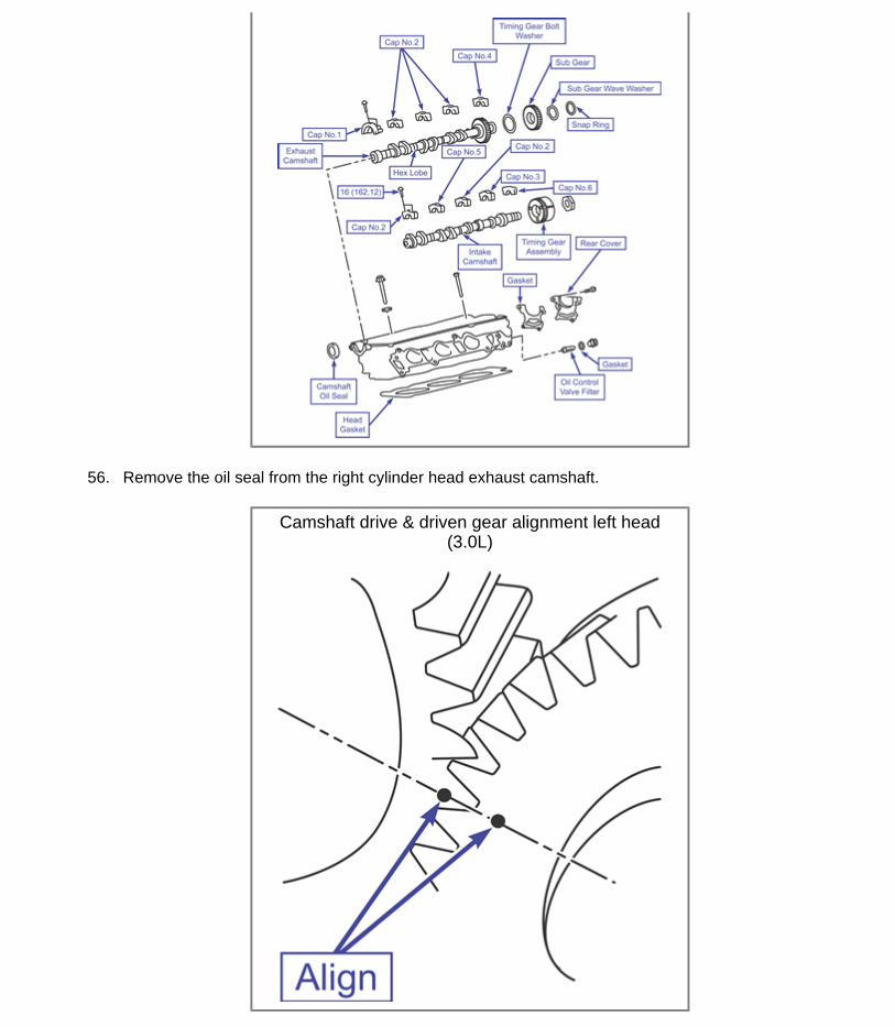
56. Remove the oil seal from the right cylinder head exhaust camshaft.
Camshaft drive & driven gear alignment left head (3.0L)
Page 8 of 30Cylinder Head, Camshafts, Upper and Lower Intake Manifolds
5/12/2011http://arrc.epnet.com/autoapp/TOY_SIE_98-03_F3/TOY_SIE_98-03_Ch3_Cylinder_Head...

57. Align the left cylinder head camshaft drive and driven gear's timing marks.
58. Secure the left cylinder head exhaust camshaft sub-gear to the main gear with a 6mm x 1.00 x 16-20mm service bolt. Tighten the bolt 48 in-lb (5.4 Nm).
Securing sub gear to main gear left head (3.0L)
Camshaft bearing cap bolt removal sequence (3.0L)
Page 9 of 30Cylinder Head, Camshafts, Upper and Lower Intake Manifolds
5/12/2011http://arrc.epnet.com/autoapp/TOY_SIE_98-03_F3/TOY_SIE_98-03_Ch3_Cylinder_Head...
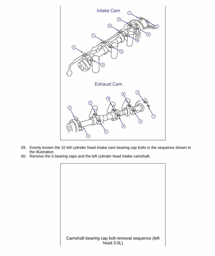
59. Evenly loosen the 10 left cylinder head intake cam bearing cap bolts in the sequence shown in the illustration.
60. Remove the 5 bearing caps and the left cylinder head intake camshaft.
Camshaft bearing cap bolt removal sequence (left head 3.0L)
Page 10 of 30Cylinder Head, Camshafts, Upper and Lower Intake Manifolds
5/12/2011http://arrc.epnet.com/autoapp/TOY_SIE_98-03_F3/TOY_SIE_98-03_Ch3_Cylinder_Head...

61. Loosen the 10 left cylinder head exhaust cam bearing cap bolts evenly in the sequence shown in the illustration.
62. Remove the 5 bearing caps and the exhaust camshaft from the left cylinder head. 63. Remove the oil seal from the exhaust camshaft. 64. Remove the exhaust camshaft sub-gear as follows:
Clamp the camshaft in a vise on the hexagonal lobe.
Sub gear removal
Page 11 of 30Cylinder Head, Camshafts, Upper and Lower Intake Manifolds
5/12/2011http://arrc.epnet.com/autoapp/TOY_SIE_98-03_F3/TOY_SIE_98-03_Ch3_Cylinder_Head...

Turn the sub-gear counterclockwise, and remove the service bolt. Remove the snap ring. Remove the wave washer, camshaft sub-gear and camshaft gear spring. Remove the valve lifters from the cylinder head bores. Inspect the valve lifters and replace if necessary.
65. Remove the center rear (right head) or center front (left head) recessed head bolt as shown in
Center rear bolt removal right head
Center front bolt left head
Page 12 of 30Cylinder Head, Camshafts, Upper and Lower Intake Manifolds
5/12/2011http://arrc.epnet.com/autoapp/TOY_SIE_98-03_F3/TOY_SIE_98-03_Ch3_Cylinder_Head...
the illustration.
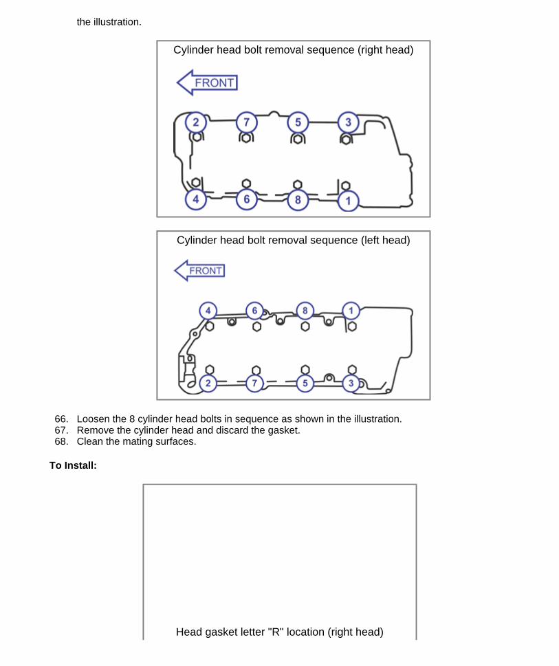
66. Loosen the 8 cylinder head bolts in sequence as shown in the illustration. 67. Remove the cylinder head and discard the gasket. 68. Clean the mating surfaces.
To Install:
Cylinder head bolt removal sequence (right head)
Cylinder head bolt removal sequence (left head)
Head gasket letter "R" location (right head)
Page 13 of 30Cylinder Head, Camshafts, Upper and Lower Intake Manifolds
5/12/2011http://arrc.epnet.com/autoapp/TOY_SIE_98-03_F3/TOY_SIE_98-03_Ch3_Cylinder_Head...

1. Install a new head gasket on the cylinder block with the "L" letter facing up (left head) or the "R" letter upside down (right head) as shown in the illustrations.
2. Install the cylinder head on the engine block. 3. Apply a light coat of oil on the head bolt threads and under the bolt heads.
Head gasket letter "L" location (left head)
Head bolt tightening sequence (right head)
Page 14 of 30Cylinder Head, Camshafts, Upper and Lower Intake Manifolds
5/12/2011http://arrc.epnet.com/autoapp/TOY_SIE_98-03_F3/TOY_SIE_98-03_Ch3_Cylinder_Head...

4. Tighten the head bolts shown in the illustrations using 3 steps as follows: Step 1: Tighten 40 ft-lb (54 Nm) Step 2: Tighten an additional 90 degrees Step 3: Tighten the center rear/front recessed bolt 14 ft-lb (19 Nm)
5. Install the exhaust camshaft sub-gear as follows: 6. Clamp the camshaft in a vise on the hexagonal lobe. 7. Install the camshaft gear spring. 8. Install the camshaft sub-gear.
Head bolt tightening sequence (left head)
Center rear bolt installation (right head)
Center front bolt (left head)
Page 15 of 30Cylinder Head, Camshafts, Upper and Lower Intake Manifolds
5/12/2011http://arrc.epnet.com/autoapp/TOY_SIE_98-03_F3/TOY_SIE_98-03_Ch3_Cylinder_Head...

9. Install the wave washer. 10. Install the snap ring. 11. Align the holes of the camshaft main gear and sub-gear by turning the camshaft sub-gear
counterclockwise, and temporarily install a service bolt. 12. Align the gear teeth of the main gear and sub-gear, and tighten the service bolt 48 in-lb (5.4
Nm).
CAUTION Since the thrust clearance of the camshaft is tight, the camshaft must be kept level while it is being installed. If it is not kept level, damage to the cylinder head or to the camshaft may result.
13. Apply new engine oil to the thrust portion and journal of the right cylinder head exhaust camshaft.
Camshafts & right cylinder head exploded view (3.0L)
Exhaust cam timing marks (right head 3.0L)
Page 16 of 30Cylinder Head, Camshafts, Upper and Lower Intake Manifolds
5/12/2011http://arrc.epnet.com/autoapp/TOY_SIE_98-03_F3/TOY_SIE_98-03_Ch3_Cylinder_Head...

14. Place the right cylinder head exhaust camshaft at a 90° angle to the timing mark (2 dot marks) on the cylinder head.
15. Apply multi-purpose grease to a new exhaust camshaft oil seal lip. 16. Install the oil seal on the exhaust camshaft.
NOTE: Do not turn over the oil seal lip. Insert the oil seal until it stops.
17. Apply sealer to the No. 1 exhaust camshaft bearing cap as shown in the illustration.
NOTE: Install the bearing cap within 5 minutes after applying sealer. Do not expose the seal to engine oil for at least 2 hours after installing.
18. Install the 5 right cylinder head exhaust camshaft bearing caps in their proper locations using the identification numbers on the bearing caps.
19. Apply a light coat of engine oil on the threads of the bearing cap bolts.
No.1 bearing cap sealant location
Page 17 of 30Cylinder Head, Camshafts, Upper and Lower Intake Manifolds
5/12/2011http://arrc.epnet.com/autoapp/TOY_SIE_98-03_F3/TOY_SIE_98-03_Ch3_Cylinder_Head...

20. Evenly tighten the right cylinder head exhaust cam bearing cap bolts in the sequence shown in the illustration 12 ft-lbs (16 Nm).
CAUTION Since the thrust clearance of the camshaft is tight, the camshaft must be kept level while it is being installed. If it is not kept level, damage to the cylinder head or to the camshaft may result.
21. Apply new engine oil to the thrust portion and journal of the right cylinder head intake camshaft.
Camshaft bearing cap bolt installation sequence right head (3.0L)
Camshaft drive & driven gear alignment (3.0L)
Page 18 of 30Cylinder Head, Camshafts, Upper and Lower Intake Manifolds
5/12/2011http://arrc.epnet.com/autoapp/TOY_SIE_98-03_F3/TOY_SIE_98-03_Ch3_Cylinder_Head...

22. Align the right cylinder head intake camshaft drive and driven gear's timing marks. 23. Place the right cylinder head intake camshaft on the cylinder head. 24. Install the 5 bearing caps in their proper locations using the identification numbers on the bearing
caps. 25. Apply a light coat of engine oil on the threads of the bearing cap bolts.
Camshaft bearing cap bolt installation sequence (3.0L)
Page 19 of 30Cylinder Head, Camshafts, Upper and Lower Intake Manifolds
5/12/2011http://arrc.epnet.com/autoapp/TOY_SIE_98-03_F3/TOY_SIE_98-03_Ch3_Cylinder_Head...

26. Evenly tighten the right cylinder head intake cam bearing cap bolts in the sequence shown in the illustration 12 ft-lbs (16 Nm).
27. Remove the service bolt from the intake camshaft.
CAUTION Since the thrust clearance of the camshaft is tight, the camshaft must be held level while it is being installed. If it is not held level, damage to the cylinder head or to the camshaft may result.
28. Apply new engine oil to the thrust portion and journal of the left cylinder head camshaft.
Exhaust cam timing mark angle (left head 3.0L)
Page 20 of 30Cylinder Head, Camshafts, Upper and Lower Intake Manifolds
5/12/2011http://arrc.epnet.com/autoapp/TOY_SIE_98-03_F3/TOY_SIE_98-03_Ch3_Cylinder_Head...

29. Place the exhaust camshaft at a 90°angle to the timing mark (1 dot mark) on the left cylinder head.
30. Apply multi-purpose grease to a new oil seal lip. 31. Install the oil seal on the left cylinder head exhaust camshaft.
Note: Do not turn over the oil seal lip. Insert the oil seal until it stops.
32. Apply sealer to the No. 1 bearing cap as shown in the illustration.
No. 1 bearing cap sealant location (3.0L)
Page 21 of 30Cylinder Head, Camshafts, Upper and Lower Intake Manifolds
5/12/2011http://arrc.epnet.com/autoapp/TOY_SIE_98-03_F3/TOY_SIE_98-03_Ch3_Cylinder_Head...

Note: Install the bearing cap within 5 minutes after applying sealer. Do not expose the seal to engine oil for at least 2 hours after installing.
33. Install the left cylinder head exhaust bearing caps in their proper locations using the identification marks on the bearing caps.
34. Apply a light coat of engine oil to the threads of the exhaust bearing cap bolts.
35. Tighten the exhaust bearing cap bolts evenly in the sequence shown in the illustration 12 ft-lb (16 Nm).
CAUTION Since the thrust clearance of the camshaft is tight, the camshaft must be kept level while it is being installed. If it is not kept level, damage to the cylinder head or to the camshaft may result.
36. Apply new engine oil to the thrust portion and journal of the left cylinder head intake camshaft.
Camshaft exhaust bearing cap bolt installation (left head 3.0L)
Camshaft drive & driven gear alignment left head (3.0L)
Page 22 of 30Cylinder Head, Camshafts, Upper and Lower Intake Manifolds
5/12/2011http://arrc.epnet.com/autoapp/TOY_SIE_98-03_F3/TOY_SIE_98-03_Ch3_Cylinder_Head...
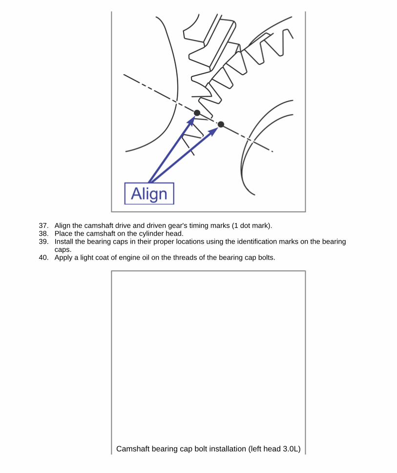
37. Align the camshaft drive and driven gear's timing marks (1 dot mark). 38. Place the camshaft on the cylinder head. 39. Install the bearing caps in their proper locations using the identification marks on the bearing
caps. 40. Apply a light coat of engine oil on the threads of the bearing cap bolts.
Camshaft bearing cap bolt installation (left head 3.0L)
Page 23 of 30Cylinder Head, Camshafts, Upper and Lower Intake Manifolds
5/12/2011http://arrc.epnet.com/autoapp/TOY_SIE_98-03_F3/TOY_SIE_98-03_Ch3_Cylinder_Head...

41. Tighten the intake bearing cap bolts evenly in the sequence shown in the illustration 12 ft-lb (16 Nm).
42. Remove the service bolt. 43. Turn the camshaft and position the cam with the lobe pointing up. Check and adjust the valve
clearance. 44. Install sealant and install the semi-circular plugs on the cylinder heads. 45. Install the cylinder head covers as follows:
Cylinder head cover sealant locations (3.0L)
Page 24 of 30Cylinder Head, Camshafts, Upper and Lower Intake Manifolds
5/12/2011http://arrc.epnet.com/autoapp/TOY_SIE_98-03_F3/TOY_SIE_98-03_Ch3_Cylinder_Head...
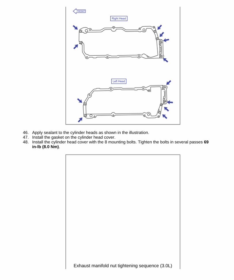
46. Apply sealant to the cylinder heads as shown in the illustration. 47. Install the gasket on the cylinder head cover. 48. Install the cylinder head cover with the 8 mounting bolts. Tighten the bolts in several passes 69
in-lb (8.0 Nm).
Exhaust manifold nut tightening sequence (3.0L)
Page 25 of 30Cylinder Head, Camshafts, Upper and Lower Intake Manifolds
5/12/2011http://arrc.epnet.com/autoapp/TOY_SIE_98-03_F3/TOY_SIE_98-03_Ch3_Cylinder_Head...

49. Using a new gasket, Install the right exhaust manifold with the 6 nuts. Using several steps tighten the nuts in the sequence shown in the illustration 36 ft-lb (49 Nm).
50. Install and secure the exhaust manifold heat shield. 51. Connect the bank 1 sensor 1 HO2S sensor harness connector. 52. Install the power steering pump bracket with the mounting bolts. Tighten 32 ft-lb (43 Nm). 53. Using a new O-ring, install and secure the dipstick tube on the engine block with the mounting
bolt.
Page 26 of 30Cylinder Head, Camshafts, Upper and Lower Intake Manifolds
5/12/2011http://arrc.epnet.com/autoapp/TOY_SIE_98-03_F3/TOY_SIE_98-03_Ch3_Cylinder_Head...

54. Using a new gasket, install the left exhaust manifold with the 6 nuts. Using several steps tighten the nuts in the sequence shown in the illustration 36 ft-lb (49 Nm).
55. Install and secure the left exhaust manifold heat shield with the 3 mounting bolts. 56. Connect the bank 2 sensor 1 HO2S sensor harness connector.
Exhaust manifold nut tightening sequence (3.0L)
Page 27 of 30Cylinder Head, Camshafts, Upper and Lower Intake Manifolds
5/12/2011http://arrc.epnet.com/autoapp/TOY_SIE_98-03_F3/TOY_SIE_98-03_Ch3_Cylinder_Head...

57. Using a new O-ring install the water inlet pipe on the cylinder head with the mounting bolt. Tighten 14 ft-lb (20 Nm).
58. Install and secure the rear cylinder head plate. 59. Install the wire harness shield. 60. Install the camshaft oil control valves. 61. Install the camshaft position sensors. 62. Using a new gasket, install the rear timing belt cover with the 6 mounting bolts. Tighten 74 in-lb
(8.5 Nm). 63. Install and secure the 3 engine harness retainers on the rear belt cover. 64. Install the timing belt upper idler pulley with the mounting bolt. Tighten 32 ft-lb (44 Nm).
65. Align the pin on the camshaft with the notch on the pulley. Install the camshaft timing pulleys with the belt guide properly oriented (right pulley belt guide to the front, left pulley belt guide to the rear). Tighten the mounting bolts 94 ft-lb (125 Nm).
66. Install the timing belt. 67. Install the spark plugs. 68. Install the ignition coils. 69. Connect the water outlet to the bypass hose.
Camshaft timing pulley installation (3.0L)
Upper & lower intake manifold 3.0L exploded view
Page 28 of 30Cylinder Head, Camshafts, Upper and Lower Intake Manifolds
5/12/2011http://arrc.epnet.com/autoapp/TOY_SIE_98-03_F3/TOY_SIE_98-03_Ch3_Cylinder_Head...

70. Using 2 new gaskets, install the water outlet with the 2 bolts, 2 washers and 2 nuts. Tighten 11 ft-lb (15 Nm).
71. Connect the ECT sender gauge connector. 72. Connect the ECT sensor connector. 73. Connect the ground strap connector. 74. Connect the upper radiator hose. 75. Connect the coolant reservoir hose. 76. Install the lower intake manifold assembly as follows:
77. Install the lower intake manifold with the fuel rail on the cylinder heads with the 9 bolts, 2 washers and 2 nuts. Tighten the mounting bolts in the sequence shown in the illustration 11 ft-lb (15 Nm).
Lower intake manifold bolt tightening sequence (3.0L)
Page 29 of 30Cylinder Head, Camshafts, Upper and Lower Intake Manifolds
5/12/2011http://arrc.epnet.com/autoapp/TOY_SIE_98-03_F3/TOY_SIE_98-03_Ch3_Cylinder_Head...

78. Connect the fuel inlet hose to the fuel filter. 79. Connect the heater hose to the intake manifold. 80. Connect the 6 fuel injector harness connectors. 81. Re-tighten the water inlet bolts 11 ft-lb (15 Nm). 82. Install the upper intake manifold on the lower intake manifold as follows:
Install and tighten the 2 mounting bolts and 2 nuts using several passes 32 ft-lb (43 Nm). Install the throttle body bracket with the 2 mounting bolts. Tighten 14 ft-lb (20 Nm). Connect the 2 ACIS vacuum hoses to the vacuum tank. Connect the purge hose to the pipe on the emission control valve set. Connect the air assist hose to the throttle body. Connect the 2 water bypass hoses to the throttle body. Connect the brake booster vacuum hose to the upper intake manifold. Connect the ground cable to the upper intake manifold. Connect the ground strap and cable to the intake air control valve. Connect the PCV valve hose to the right cylinder head. Install and secure the PS hose on the engine hanger bracket with the 2 nuts. Connect the EVAP VSV connector. Connect the 2 VSV connectors for the acoustic control induction system (ACIS). Connect the IAC valve connector. Connect the throttle position sensor connector. Connect the accelerator cable.
83. Install the air cleaner cover and inlet duct with the resonator. 84. Install the engine cover. 85. Install the front exhaust pipe, 86. Install the power steering pump. 87. Install the drive belt. 88. Install the upper cowl panel. 89. Install the cowl support brace. 90. Install the wiper transmission assembly. 91. Install the cowl air intake cover. 92. Install the wiper arms. 93. Install the right front inner fender panel. 94. Fill the cooling system. 95. Check for leaks.
Page 30 of 30Cylinder Head, Camshafts, Upper and Lower Intake Manifolds
5/12/2011http://arrc.epnet.com/autoapp/TOY_SIE_98-03_F3/TOY_SIE_98-03_Ch3_Cylinder_Head...