cx813 manual - busy bee tools · 2016-07-27 · model cx813 - 12" x 18" mini wood lathe...
TRANSCRIPT

CX813 12" x 18" MINI WOOD LATHE WITH VARIABLE SPEED & DIGITAL READOUT
USER MANUAL
Version 1.0

2
TABLE OF CONTENT
General Safety Instructions ....................................................................... 3
Specific Safety Instructions ...................................................................... 4
Heavy Duty Bench Top Lathe Features..................................................... 5
Physical Features...................................................................................... 6
Un-packing ............................................................................................... 7
Setup......................................................................................................... 7
Bench Mounting ........................................................................................ 7
Assembly................................................................................................... 8
Installing/Removing Headstock Center...................................................... 8
Installing/Removing Tailstock Center ........................................................ .9
Installing/Removing Faceplate .................................................................. 9
Installing Tool Rest .................................................................................... .9
Test Run....................................................................................................10
ON/OFF Switch .........................................................................................10
Operation...................................................................................................11
Stock Inspection ........................................................................................11
Changing Spindle Speed...........................................................................12
Adjusting Tailstock ....................................................................................13
Adjusting Tool Res ....................................................................................13
Alignment Between Centers ......................................................................14
Maintenance..............................................................................................14
Belt Replacement ......................................................................................15
Trouble Shooting .......................................................................................16
CX813 Parts Breakdown ............................................................ ...............17
CX813 Pars List ............................................................ ............................17
Warranty ....................................................................................................20

3
GENERAL SAFETY INSTRUCTIONS
Do not attempt to operate the machine until you have read thoroughly and have understood completely all instructions, rules and conditions contained in this manual. Failure to comply can result in accidents involving fire, electric shock, or serious personal injury.
Know your machine. For your safety, read the owner’s manual carefully. Learn its applications and limitations, as well as specific potential hazards pertinent to this machine.
Make sure all tools are properly
grounded. If the tool electrical plug has three prongs, it should be used in a three hole electrical socket. If three prongs or two prongs adapter is used, the adapter plug must be properly grounded. Do not remove or disable the third prong.
Keep all the guards in place and in
good working order. If a guard must be removed for maintenance or cleaning, make sure it is properly attached before using the machine again.
Remove adjusting keys and
wrenches. Form a habit of checking to see that the keys and adjusting wrenches are removed from the machine.
Keep your work area clean.
Cluttered areas and workbenches increase the chance if an accident.
Do not use the machine in dangerous environments.
Do not use power tools in damp or
wet locations or expose them to rain. Keep work areas well illuminated.
Keep children away. All visitors
should keep a safe distance from the work area.
Do not force the machine. It will do
the job better and be safe at the operating rate for which it is designed. Do not force the machine or attachments to do a job for which they are not designed.
Wear proper apparel. Avoid loose
clothing, gloves, neckties, rings, bracelets and jewelry which could get caught in moving parts. Non-slip footwear is recommended. Wear protective hair covering to contain long hair.
Always use safety glasses. Also,
wear a face or dust mask if the operation area is dusty. Everyday eyeglasses only have impact resistant lenses. They are not safety glasses.

4
CX813 HEAVY DUTY BENCHTOP LATHE SPECIFIC SAFETY INSTRUCTIONS
Like all power tools and machinery, proper safety and attention must be adhered to. There is danger associated with using any tool or machine so pay careful attention each and every time you use your tool. If you are not familiar with the operations of a lathe, you should obtain the advice and/or instructions from a qualified professional.
Read this operation manual carefully and understand it before operating the lathe.
Before mounting the work-piece cut
off some waste portions with a band saw or other tool to ensure the work-piece has no large edges.
Verify tool rest , headstock and
tailstock are secure before turning the lathe ON.
Make sure the work-piece is secured
properly to the machine before operation.
To avoid accidental starting, make
sure the switch is in the OFF position before plugging in the power cord.
Make sure the tool rest is secured
properly and it is approximately 1/4" away and 1/8" above the work-piece.
Start and stop the machine
yourself. Do not have anybody help you do this.
Always wear face shield and safety glasses while operating the lathe.
Always operate the tools in a well-
ventilated area and provide for proper dust removal. Use a dust collection system whenever possible.
Use correct tool. Take light cuts, use
low speeds, and firmly support tool with both hands.
Do not attempt to measure the work-
piece size while the machine is running.
Make sure the work-piece is clamped
securely between the centers before starting the machine.
Only use correct size centers.
After adjusting or servicing the
machine, remember to remove all wrenches or other tools from the machine.
Never put hands or other objects on
the spinning spindle.
WARNING! The safety instructions given above can not be complete because the environment in every shop is different. Always consider safety first as it applies to your individual working conditions.

5
MODEL CX813 - 12" x 18" MINI WOOD LATHE WITH VARIABLE SPEED
As part of the growing line of Craftex woodworking equipment, we are proud to offer CX813 a Heavy Duty Bench Top Lathe. By following the instructions and procedures laid out in this owner’s manual, you will receive years of excellent service and satisfaction. The CX813 is a professional tool and like all power tools, proper care and safety procedures should be adhered to.
Main Motor........................................... 3/4 HP, 110V, 60 HZ, 5.3 Amps
Speed .................................................. 1700 RPM
Swing Over Bed................................... 12"
Swing Over Tool Rest Base................. 9-1/2"
Distance Between Centers .................. 16-1/2"
Spindle TPI .......................................... 1" x 8 TPI
Spindle Taper ...................................... MT2
Tailstock Taper .................................... MT2
Tailstock Center Type.......................... Live
Number of Spindle Speeds .................. Variable
Spindle Speed Ranges ........................ 650 - 3800 RPM
Faceplate Size ..................................... 3-1/8"
Bed Width ............................................ 7-1/4"
Bed Construction ................................. Cast Iron
Headstock Construction....................... Cast Iron
Tailstock Construction ......................... Cast Iron
Dimensions .......................................... 39" L x 12" W x 17" W
Approx. Weight .................................... 84 lbs.
Warranty .............................................. 3 Year
CX813 - 12" x 18" MINI WOOD LATHE FEATURES

6
PHYSICAL FEATURES

7
UNPACKING
The machine is properly packaged in a carton for safe transportation. When unpacking, carefully inspect the crate and ensure that nothing has been damaged during transit. Open the crate and check that the machine is in a good condition. There is a bag which contains some loose parts of the machine. After the machine has been un-packed, check that all loose parts shown in Figure-1 are present.
Figure-1 Loose parts
1. Lathe (not shown)
2. Tool Rest
3. Tailstock Center (Live Center) MT2
4. Headstock Center (Dead Center) MT2
5. Knock-Out Bar
6. Allen Wrenches
SETUP
Before starting setting up the machine you need to read and understand this user manual completely. For the protection of your eyes you need to have safety glasses. The unpainted surfaces or parts of the lathe are coated with rust prevention waxy oil and you will want to remove this before you begin assembly. Use a solvent cleaner that will not damage painted surfaces.
BENCH MOUNTING
The lathe features four pre-drilled holes on its base which allow mounting it to the workbench. There are two ways to mount the lathe onto the workbench; through mount and direct mount. "Through Mount" is the strongest mounting option where the holes are drilled all the way through the workbench. Hex bolts, washers and hex nuts are used to secure the lathe to the workbench. See figure-2.
Figure-2 Through mount
IMPORTANT While doing inventory, if you can not find any part, check if the part is already installed on the machine.

8
"Direct Mount" is to simply secure the lathe to the workbench using lag screws. See figure-3.
Figure-3 Direct mount Place the lathe on the workbench and use the holes on the base as a guide for drilling and attaching the shear to the workbench.
ASSEMBLY
Attach the electrical box to the lathe and secure it using the two pre installed Philips head screws and two flat washers as shown in figure-4.
Figure-4 Installing the electrical box Insert hand wheel handle into the quill hand wheel and tighten with flathead screw driver.
INSTALLING / REMOVING HEADSTOCK CENTER
The headstock spindle is designed with an MT2 taper. Clean the spindle bore and center's taper and insert the center into the spindle bore firmly by hand. Check is the center is securely installed by giving it a quick tug. A properly installed center will not pull out by hand.
WARNING! CX813 weighs approximately 84 lbs. Do not over-exert yourself. Get the help of an assistant for safe moving.
WARNING! Make sure switch is in the OFF position the cord is disconnected from the power source before installing or removing any parts on the machine.

9
REMOVING THE CENTER
Removing the drive center is done by simply knocking it out, using the supplied knock-out bar. When knocking out the center, hold it by hand to prevent it dropping down. See Figure-5.
Figure-5 Knocking out the drive center with the help of knock-out bar
INSTALLING / REMOVING TAILSTOCK CENTER
Clean the tailstock center shank and the tailstock quill and insert the center firmly by hand into the tailstock quill. REMOVING THE CENTER
Simply turn the quill movement hand-wheel until the quill end is nearly inside the tailstock. Then loosen the quill fix lever and you can move the quill in or out. See Figure-6.
Figure-6 Installing / Removing tailstock
INSTALLING / REMOVING FACEPLATE
Make sure the switch is in OFF position and the cord is disconnected from the power source. Attach the faceplate to the headstock by threading it on the spindle. Now, use knock-out bar and tighten the faceplate as shown in the in Figure-7.
Figure-7 Installing the faceplate REMOVING THE FACEPLATE
When you want to remove the faceplate, simply do the above procedure in reverse.
INSTALLING TOOL REST
Insert the tool rest and turn the lock handle to secure the tool rest in position. See Figure-8.
Figure-8 Installing the tool rest
10
TEST RUN
Once you have assembled your machine completely, it is time for a test run to make sure that the machine works properly and is ready for operation. Carefully look around your machine before turning it on to ensure no tools are left on the machine, all screws and knobs are securely fastened, and all controls are working properly.
TO TEST RUN THE MACHINE:
Make sure all the tools used during set up are cleared away from the machine. Connect the machine to the correct power outlet. Turn the machine ON and verify the machine. The machine should run smoothly without excessive vibration or noise. Turn the machine OFF. Remove the key from the ON/OFF switch and try to start the machine. The machine should not start. If the machine does not start, it means the switch disabling features it working properly.
During the test run the machine should run smoothly and create very little noise or vibration. If there is an unusual noise coming from the machine or the machine vibrates excessively, turn the machine OFF immediately and investigate the problem.
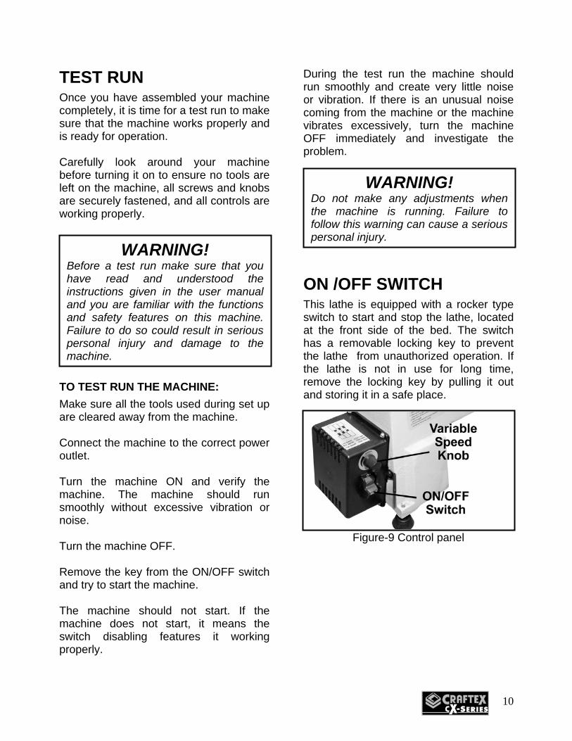
ON /OFF SWITCH
This lathe is equipped with a rocker type switch to start and stop the lathe, located at the front side of the bed. The switch has a removable locking key to prevent the lathe from unauthorized operation. If the lathe is not in use for long time, remove the locking key by pulling it out and storing it in a safe place.
Figure-9 Control panel
WARNING! Before a test run make sure that you have read and understood the instructions given in the user manual and you are familiar with the functions and safety features on this machine. Failure to do so could result in serious personal injury and damage to the machine.
WARNING! Do not make any adjustments when the machine is running. Failure to follow this warning can cause a serious personal injury.

11
OPERATION
The first thing to do is to inspect the work-piece and make sure it is suitable for turning. The work-piece should not have any extreme bows, knots or cracks. Trim the work-piece to make sure it is roughly concentric. Install the work-piece between the centers or attach it to the faceplate or chuck. Adjust the tool rest to 1/8" above the work-piece and make sure the clearance between the work-piece and the tool rest lip is 1/4". Rotate the work-piece by hand to make sure the work-piece rotates freely. Position the dust collection hood close to the work-piece to collect the chips. Make sure to tie back loose hair and clothing. Wear safety glasses and respirator. Turn the lathe ON and adjust the speed using the variable speed knob. Carefully begin turning.
STOCK INSPECTION
Before cutting any wood, make sure to inspect the work-piece for nails, staples, small pieces of stone or metal and any other foreign object which is dangerous to come in contact with the blade. If the wood contains any of these objects and it comes in contact with the cutting tool, the object might fly and hit the operator or seriously damage the blade. For safety, always inspect your work-piece carefully before cutting and wear eye protection. Some woods with excessive twisting or warping are un-stable while cutting and are dangerous to cut because during operation the work-piece can move un-expectedly which can either damage the blade or hurt the operator. If a work-piece has large knots. When turning, the work-piece completely breaks into half and cause personal injury to the operator and damage to the machine.
WARNING! Before operating the lathe, make sure that you have read and understood the instructions given in the user manual and you are familiar with the functions and safety features on this machine.

12
CHANGING SPINDLE SPEED
The CX801 12" x 18" Mini Wood Lathe is variable speed lathe and feature speed ranges : 650-1450, 1250-2800, 1600-3800 RPM.
Figure-10 Speed ranges for each belt position The turning speed of the lathe is varied with the work-piece diameter to be turned. When turning a smaller diameter of work-piece, a higher spindle speed is recommended. However, proper selection of spindle speed for the work-piece is made by the operator’s experience. TO CHANGE THE SPINDLE SPEED:
Make sure the switch is in the OFF position and the cord is disconnected from the power source.
Loosen the belt tension screw so that the belt tension lever moves freely. See figure-11. Remove the rear access door. See figure 11.
Figure-11 Belt tension lever and screw Swing control box to the side to access the motor pulley. Move the belt to necessary grooves on the motor pulley and spindle pulley to achieve the desired speed shown in the speed chart located on control box and figure-10. Turn the headstock hand wheel with hand to facilitate changing of the belt position. Move the belt tension lever down to tension the belt. Retighten the belt tension lever screw. Reinstall the rear cover and close the side cover.

13
ADJUSTING TAILSTOCK
The tailstock features a cam-action clamping system to secure it to the lathe bed. TO ADJUST TAILSTOCK POSITION:
Disengage the lock lever and move the tailstock to the desired position on the bed. See figure-12.
Figure-12 Adjusting tailstock position Re-engage the lock lever to secure the tailstock on the lathe bed.
ADJUSTING TOOL REST
The tool rest base features a cam-action clamping system to secure it to the lathe bed. TO ADJUST TOOL REST BASE POSITION:
Disengage the lock lever and slide the tool rest base to the desired position on the bed. See figure-13. Re-engage the lock lever to secure the tool rest base on the lathe bed.
Figure-13 Adjusting the tool rest base ADJUSTING THE ANGLE OR HEIGHT
Loosen the base lock lever and the tool rest lock lever. Position the tool rest approximately 1/4" away from the work-piece and approximately 1/8" above the work-piece center line. Retighten the tool rest base lock lever and the tool rest lock lever.

14
ALIGNMENT BETWEEN CENTERS
The center alignment has been adjusted properly at the factory before the machine is shipped to you. However, after lengthy operation, the centers may be out of alignment. At this time center alignment needs to be done. TO ALIGN THE CENTERS:
Make sure the cord is disconnected from the power source. Remove tool rest base and the tool rest and slide the tailstock with the center towards the headstock. Loosen the four screws securing the headstock to the bed. Slightly adjust the headstock position so that the centers are aligned with each other.
Figure-14 Headstock and tailstock centers aligned
MAINTENANCE
During the life of your machine, you will need to practice some regular maintenance to keep your lathe in peak performance condition,
Check your lathe daily for: Loose mounting bolts. Damaged cord. Damaged or work belt. Worn switch or any other unsafe condition.
CLEANING
Vacuum the excess wood chips and saw dust and wipe the remaining saw dust with a dry cloth. Protect the unpainted cast iron surfaces by wiping it clean with a lightly oiled rag after every use.
WARNING! Make sure the machine is turned OFF the cord is disconnected from the power source before servicing and removing/replacing any components of the machine.

15
BELT REPLACEMENT
The drive belt stretches and gets old as the lathe is used. When the belt shows signs of excessive wear and damage you will need to replace it with a new one. TO REPLACE THE BELT:
Make sure the cord is disconnected from the power source. Remove the rear access cover and open side access cover. Release the belt tension, then remove the belt from the motor pulley. Loosen the set screws on the spindle wheel and the spindle hand wheel. See figure-15.
Figure-15 Set screw locations Tap out the spindle using a mallet. If you do no have a mallet, place a block of wood against the spindle and tap with a hammer. To get the spindle completely out, use a flat head screw driver to punch it the rest of the way. Place the new belt over the spindle pulley. Slide the spindle back through headstock and into the original position. Tap the headstock with the mallet to reseat the bearing.
Install the headstock spindle hand wheel and tighten the set screws. Tension the belt by lowering the belt tension lever and tighten the belt tension screw. Reinstall the rear access cover and close side access cover.

16
PROBLEMS
CAUSES
CORRECTION
CUTTING TOOL VIBRATION
1. Work-piece is not
clamped firmly.
1. Clamp it firmly.
POOR MACHINE ACCURACY
1. Work-piece is clamped
incorrectly. 2. Tailstock center and
headstock center is out of alignment.
3. Machine leveling loss.
1. Check balance. 2. Adjust center
Alignment. 3. Check machine
leveling periodically.
MOTOR DOES NOT RUN WHEN POWER WITCH IS TURNED ON
1. Switch is burnt out. 2. Connection wire is loose
or damaged.
1. Replace the switch.
2. Tighten or replace wire.
MOTOR DOES NOT RUN AT A FULL SPEED
1. Power voltage is too low. 2. Motor is damaged.
1. Test voltage. 2. Check and repair
motor.
MOTOR DOES NOT REACH FULL SPEED
1. Incorrect power wiring. 2. Overloaded.
1. Replace with correctly
sized power wiring. 2. Reduce load.
MOTOR OVERHEATING
1. Motor is dirty. 2. Motor is damaged.
1. Clean motor. 2. Check and repair motor.
TROUBLESHOOTING
17
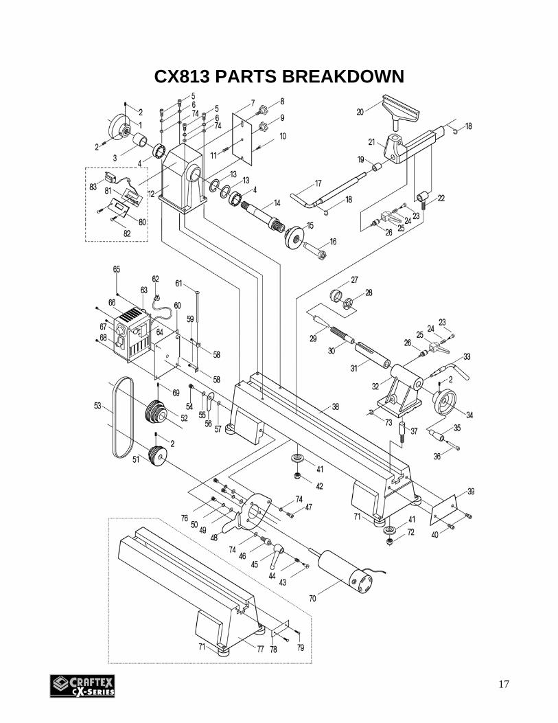
CX813 PARTS BREAKDOWN

18
CX813 PARTS LIST

19

20
WARRANTY
Craftex warrants every product to be free from defects in materials and agrees to correct such defects where applicable. This warranty covers Three Years for parts and 90 days for labour (unless specified otherwise), to the original purchaser from the date of purchase but does not apply to malfunctions arising directly or indirectly from misuse, abuse, improper installation or assembly, negligence, accidents, repairs or alterations or lack of maintenance.
Proof of purchase is necessary. All warranty claims are subject to inspection of such products or part thereof and Craftex reserves the right to inspect any returned item before a refund or replacement may be issued. This warranty shall not apply to consumable products such as blades, bits, belts, cutters, chisels, punches etceteras. Craftex shall in no event be liable for injuries, accidental or otherwise, death to persons or damage to property or for incidental contingent, special or consequential damages arising from the use of our products.
RETURNS, REPAIRS AND REPLACEMENTS
To return, repair, or replace a Craftex product, you must visit the appropriate Busy Bee Tools showroom or call 1-800-461-BUSY. Craftex is a brand of equipment that is exclusive to Busy Bee Tools.
For replacement parts directly from Busy Bee Tools, for this machine, please call 1-800-461-BUSY (2879), and have your credit card and part number handy.
All returned merchandise will be subject to a minimum charge of 15% for re-stocking and handling with the following qualifications.
Returns must be pre-authorized by us in writing. We do not accept collect shipments. Items returned for warranty purposes must be insured and shipped pre-paid to the nearest warehouse Returns must be accompanied with a copy of your original invoice as proof of purchase. Returns must be
in an un-used condition and shipped in their original packaging a letter explaining your reason for the return. Incurred shipping and handling charges are not refundable.
Busy Bee will repair or replace the item at our discretion and subject to our inspection. Repaired or replaced items will be returned to you pre-paid by our choice of carriers. Busy Bee reserves the right to refuse reimbursement or repairs or replacement if a third party without our
prior authorization has carried out repairs to the item. Repairs made by Busy Bee are warranted for 30 days on parts and labour. Any unforeseen repair charges will be reported to you for acceptance prior to making the repairs. The Busy Bee Parts & Service Departments are fully equipped to do repairs on all products purchased
from us with the exception of some products that require the return to their authorized repair depots. A Busy Bee representative will provide you with the necessary information to have this done.
For faster service it is advisable to contact the nearest Busy Bee location for parts availability prior to bringing your product in for repair.
CRAFTEX 3 YEARS LIMITED WARRANTY