curved structures - metsä wood – producer and … structures curved kerto can be manufactured...
TRANSCRIPT
_ _ _ _ _ _ _ _ _ _ _ _ _ _ _ _ _ _ _ _ _ _ _ _ _ _ _ _ _ _ _ _ _ _ _ _ _ _ _ _ _ _ _ _ _ _ _ _ _ _ _ _ _ _ _ _ _ _ _ _ _ _ _ _ _ _ _ _ _ KERTO MANUAL, CURVED BEAMS
MARCH 2017 1
CURVED STRUCTURES
Curved Kerto can be manufactured using two methods. The shape can be machined from one Kerto-Q panel or Kerto-Q or Kerto-S lamellas can be glued together to a curved beam similarly to glulam manufacturing. The methods can also be used combined (see figure 1). GLUED CURVED BEAMS
Kerto-S or Kerto-Q lamellas are bended and glued together to form a curved structure like in glulam manufacturing. The advantage of this method is, that the grain direction of the lamellas is parallel to the direction of the bending stress of the curved cross-section. Thus the bending strength of the curved beam is constant through the whole length of the beam. If not specified more in detail, Kerto-S and Kerto-Q panels can be bended in the grain direction of the surface veneer within following requirements:
Panel thickness ≤ 33 mm
Bending only in the grain direction of the surface veneers
Radius of the curvature r ≥ 250 x panel thickness
If not specified more in detail, Kerto-Q panels can be in addition bended perpendicular to the grain direction of the surface veneer within following requirements:
Panel thickness ≤ 33 mm
Radius of the curvature r perpendicular to the surface veneer grain direction ≥ 600 x panel thickness
MACHINED CURVED BEAMS
Curved beam can be easily sawn out of a Kerto-Q panel. The maximum panel size limits the possible span and the radius of the curve of the beam. Generally Kerto-Q is suitable material for curved beams manufactured this way, but in some cases with small radius of the curve also Kerto-S may be possible to use. In table 1 and 2 are shown the reduction factors in strength for Kerto-S and Kerto-Q members sawn curved.
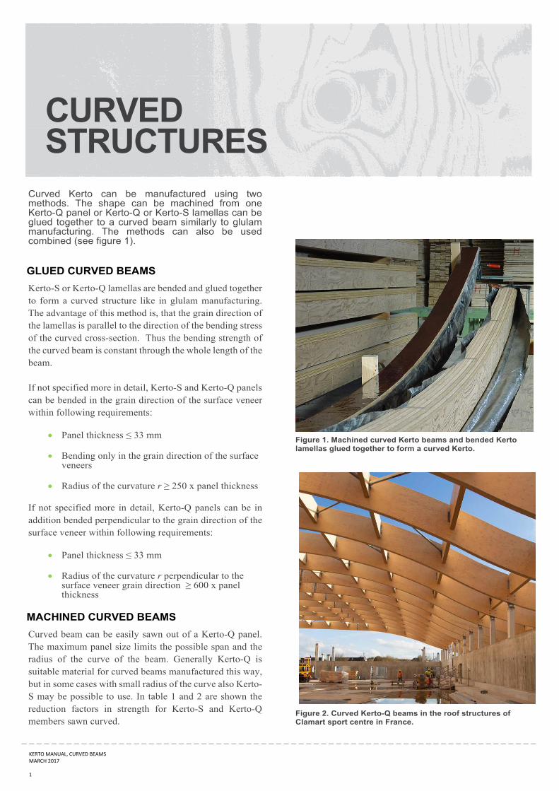
Figure 1. Machined curved Kerto beams and bended Kerto lamellas glued together to form a curved Kerto.
Figure 2. Curved Kerto-Q beams in the roof structures of Clamart sport centre in France.

_ _ _ _ _ _ _ _ _ _ _ _ _ _ _ _ _ _ _ _ _ _ _ _ _ _ _ _ _ _ _ _ _ _ _ _ _ _ _ _ _ _ _ _ _ _ _ _ _ _ _ _ _ _ _ _ _ _ _ _ _ _ _ _ _ _ _ _ _ KERTO‐KÄSIKIRJA, KAAREVAT PALKIT
SYYSKUU 2016 2
Tämä dokumentti on Metsäliitto Osuuskunnan (Metsä Wood) omaisuutta ja voimassa vain Metsä Woodin tuotteiden kanssa. Dokumentin hyödyntäminen muun valmistajan tuotteiden yhteydessä on kielletty. Metsäliitto Osuuskunta ei vastaa dokumenttien soveltamisesta tai mahdollisista virheistä dokumenteissa. Tätä lauseketta ei saa poistaa. Kerto on Metsäliitto Osuuskunnan (Metsä Wood) rekisteröimä tavaramerkki.
TABLE 1. REDUCTION FACTORS FOR STRENGTH FOR KERTO-Q, WHEN α IS THE ANGLE BETWEEN THE TANGENT OF THE CURVE AND
THE GRAIN DIRECTION OF THE SURFACE VENEER.
Angle α
0° 2,5° 5° 10° 15° 30° 45° 60° 90°
Bending, edgewise 1.00 0.90 0.75 0.55 0.40 0.25 0.20 0.20 0.22
Bending, flatwise 1.00 1.00 0.90 0.70 0.50 0.25 0.20 0.20 0.22
Tension parallel to grain 1.00 1.00 0.90 0.70 0.40 0.25 0.20 0.20 0.23
Compression parallel to grain 1.00 1.00 0.90 0.70 0.50 0.35 0.25 0.25 0.35
Modulus of elasticity 1.00 0.90 0.80 0.60 0.40 0.15 0.10 0.10 0.23
Intermediate values can be interpolated. Source: VTT-C-184/03
TABLE 2. REDUCTION FACTORS FOR STRENGTH FOR KERTO-S, WHEN α IS THE ANGLE BETWEEN THE TANGENT OF THE CURVE AND
THE GRAIN DIRECTION OF THE SURFACE VENEER.
Angle α
0° 2,5° 5° 10° 15° 30° 45° 60° 90°
Bending, edgewise 1.00 0.90 0.75 0.45 0.25 0.10 0.05 0.05 0.02
Bending, flatwise 1.00 0.90 0.80 0.55 0.30 0.10 0.05 0.05 0.02
Tension parallel to grain 1.00 1.00 0.90 0.60 0.30 0.05 0.02 0.02 0.02
Compression parallel to grain 1.00 1.00 0.90 0.65 0.40 0.20 0.17 0.17 0.17
Modulus of elasticity 1.00 0.90 0.80 0.60 0.40 0.15 0.05 0.05 0.03
Intermediate values can be interpolated. Source: VTT-C-184/03
Figure 3. Archs cut from Kerto-Q panels.
Figure 4. Curved structure from inside.

_ _ _ _ _ _ _ _ _ _ _ _ _ _ _ _ _ _ _ _ _ _ _ _ _ _ _ _ _ _ _ _ _ _ _ _ _ _ _ _ _ _ _ _ _ _ _ _ _ _ _ _ _ _ _ _ _ _ _ _ _ _ _ _ _ _ _ _ _ KERTO MANUAL, CURVED STRUCTURES
MARCH 2017 3
This document is property of Metsäliitto Cooperative (Metsä Wood) and is only applicable when used along with products produced by Metsä Wood. Use of the document for other manufacturer's product is prohibited. Metsäliitto Cooperative is not responsible for application of documents or possible faults in documents. This clausul must not be removed. Metsä Wood and Kerto are registered trademarks of Metsäliitto Cooperative (Metsä Wood).
Figure 4. Kerto-Q characteristic properties in relation to angle between the tangent of the curve and the grain direction of the surface veneer.
Figure 5. Kerto-S characteristic properties in relation to angle between the tangent of the curve and the grain direction of the surface veneer.
0
2000
4000
6000
8000
10000
12000
0
5
10
15
20
25
30
35
40
0° 2,5° 5° 10° 15° 30° 45° 60° 90°
Modulus of elasticity (N/m
m²)
Characteristic stren
gth (N/m
m²)
Angle α between the tangent of the curve and the grain direction of the surface veneer
Kerto‐Q
Bending, edgewise (h ≤ 300 mm)
Bending, flatwise
Tension parallel to grain (L ≤ 3 m)
Compression parallel to grain