current-mode variable frequency quadrature sinusoidal oscillators using two ccs and four passive...
TRANSCRIPT

MIXED SIGNAL LETTER
Current-mode variable frequency quadrature sinusoidaloscillators using two CCs and four passive components includinggrounded capacitors: a supplement
Abhirup Lahiri
Received: 5 January 2011 / Revised: 19 March 2011 / Accepted: 19 March 2011 / Published online: 3 April 2011
� Springer Science+Business Media, LLC 2011
Abstract This letter comments on the recently published
paper in [1] which provides realizations of minimum
component quadrature sinusoidal oscillators. On re-exam-
ination of the ‘Type 3’ oscillator circuits in [1], it has been
found that the circuits actually suffer from ‘latch up’
problem due to use of incorrect polarity of the CCII based
negative-impedance convertor. This problem has been
corrected (without altering the characteristic equation) by
swapping the impedances at y and x terminals. Explicit
quadrature current outputs are derived similarly as
done in [1].
1 Corrected circuits
The circuits proposed in Fig. 3 of [1] and referred to as
Type 3 oscillators therein, employ incorrect configuration
of the negative impedance convertor [created using CCII?
in Fig. 3(a) and CCI in Fig. 3(b)]. Due to the incorrect
polarities of the employed negative impedance convertor
(NIC), the circuit which is supposed to function as a sin-
uosoidal oscillator and obey the characteristic equation as
given in (9) of [1], can actually ‘latch up’ making y ter-
minal of first CCII go to either of the supply rails. The
problem actually arises in practical circuits (and not in
‘ideal CCII’) wherein the transfer function of y to x termi-
nal and x to z terminal are associated with ‘non-infinite
frequency’ poles. Thus, similar to any real voltage-opera-
tional amplifier based buffer connected in positive feed-
back, the circuit in Fig. 3 of [1] can latch and thereby
Fig. 1 Corrected Type 3 CM QOs
A. Lahiri (&)
Netaji Subhas Institute Of Technology, 36B, J and K Pocket,
Dilshad Garden, Delhi, India
e-mail: [email protected]
123
Analog Integr Circ Sig Process (2011) 68:129–131
DOI 10.1007/s10470-011-9635-4
failing to provide the correct DC operating point to make
the CCs functional (as voltage buffer between y and x ter-
minal and current buffer between x and z terminal).
The problem has been corrected (without altering the
characteristic equation as given in (9) of [1]) by simply
swapping impedances at y and x terminals of the first CCII
(i.e. now the NIC has correct terminal polarities to guar-
antee correct DC point within the linear range of CC). The
corrected circuits are shown in Fig. 1 and the explicit
quadrature current outputs are derived similarly as done in
[1]. It is worth mentioning that the circuit is similar to the
oscillator in Fig. 7 of [2] which employs a CFOA based
NIC. The circuits have been verified through SPICE sim-
ulations using the MOSFET implementation of CCII
in Fig. 5 and CCI in Fig. 4 of [1]. The circuits have
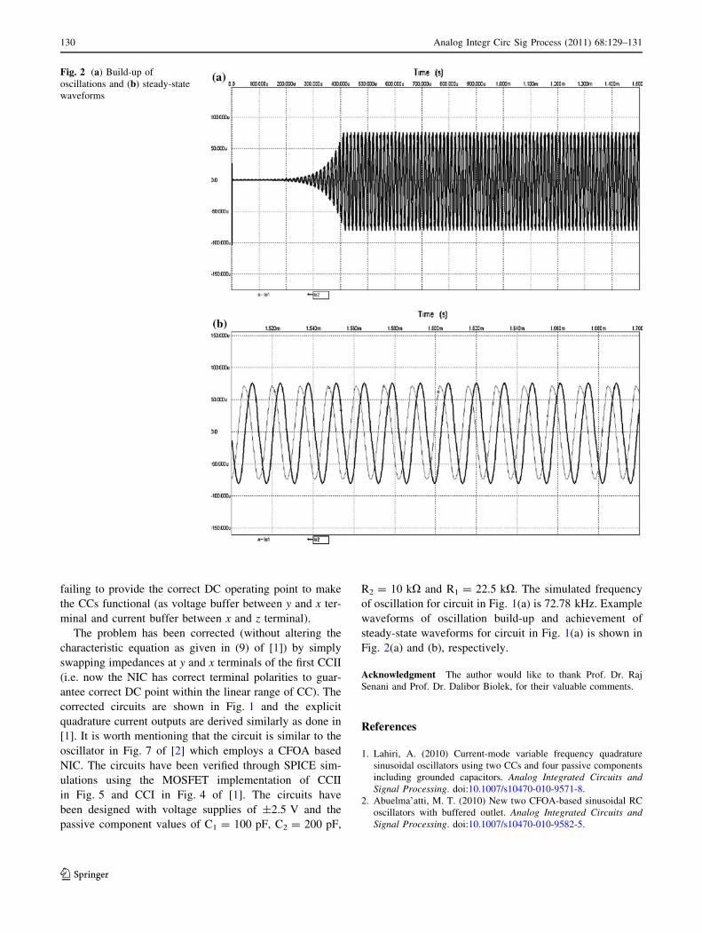
been designed with voltage supplies of ±2.5 V and the
passive component values of C1 = 100 pF, C2 = 200 pF,
R2 = 10 kX and R1 = 22.5 kX. The simulated frequency
of oscillation for circuit in Fig. 1(a) is 72.78 kHz. Example
waveforms of oscillation build-up and achievement of
steady-state waveforms for circuit in Fig. 1(a) is shown in
Fig. 2(a) and (b), respectively.
Acknowledgment The author would like to thank Prof. Dr. Raj
Senani and Prof. Dr. Dalibor Biolek, for their valuable comments.
References
1. Lahiri, A. (2010) Current-mode variable frequency quadrature
sinusoidal oscillators using two CCs and four passive components
including grounded capacitors. Analog Integrated Circuits andSignal Processing. doi:10.1007/s10470-010-9571-8.
2. Abuelma’atti, M. T. (2010) New two CFOA-based sinusoidal RC
oscillators with buffered outlet. Analog Integrated Circuits andSignal Processing. doi:10.1007/s10470-010-9582-5.
Fig. 2 (a) Build-up of
oscillations and (b) steady-state
waveforms
130 Analog Integr Circ Sig Process (2011) 68:129–131
123
Abhirup Lahiri received
Bachelor of Engineering (B.E.)
degree from the Division of
Electronics and Communica-
tions, Netaji Subhas Institute of
Technology (erstwhile, Delhi
Institute of Technology), Uni-
versity of Delhi, India. His
research interests include design
of compact analog circuit solu-
tions using novel voltage-
mode and current-mode active
elements. He has authored/
co-authored several interna-
tional journal/conference papers
(including fifteen SCI/SCI-E journals) and has acted as a reviewer (by
editor’s invitation) for international journals and conferences. He is a
member of ACEEE, IAENG and IACSIT.
Analog Integr Circ Sig Process (2011) 68:129–131 131
123