current developments in the hcu mobile mapping...
TRANSCRIPT
Current Developments in the HCU Mobile Mapping Systems and Its Use in Research and Teaching, (6995) Friedrich Keller, Sören Leitz, Steffen Kagerah, Gordeon Thie and Harald Sternberg (Germany) FIG Congress 2014 Engaging the Challenges - Enhancing the Relevance Kuala Lumpur, Malaysia 16 – 21 June 2014
1/14 Current
Current Developments in the HCU Mobile Mapping Systems and Its Use in Research and Teaching
Friedrich Keller, Sören Leitz, GordeonThie, Steffen Kagerahand and Harald Sternberg,
Germany
Key words: Mobile Mapping System, Research and Teaching SUMMARY At the HafenCity University a mobile mapping system has been developed in recent years. Consisting of an inertial measurement unit (type: IMAR RQH-1003), a GNSS receiver (Novatel OEMV-2), an odometer and a terrestrial laser scanner (Z + F IMAGER 5010), it is used in various fields. From the very beginning the installation of the system on different types of vehicles was in the foreground. So it can be mounted inside the building on a trolley or outside on various motor vehicles or ships. This versatility is made possible by a modular construction of the instruments. The central module here is the IMU, which is fixedly connected to the module carrier. It forms the center of the measuring system, both topologically and geometrically. This year, the measurement system has been extended by two digital cameras (Point Grey Flea3) and two profile scanner (Sick LMS 151). Due to the easy expandability and versatility of the system, a variety of current research issues around MMS can be edited. Exactly these questions reflect the trend towards the kinematic and thus faster surveying. The system is actively used in research-based learning so that students and young researchers are able to participate on this trend. The results of several theses are presented here in summary: The basis for the following thesis has been given in the master’s thesis "Evaluation and calibration of a mobile mapping system”. The calibration method developed in this study was taken up and examined in detail in the bachelor’s thesis "Review and further development of the calibration of a mobile mapping system". For the extension of the system with two cameras, a master's thesis “Investigations of trajectories with the stereo camera system” has been developed which deals with the topic of automatic registration of image data. Furthermore the bachelor’s thesis "Generation of 3D point clouds from image data of a mobile mapping system" serves to automatically generate point clouds from the acquired image data using the ‘structure from motion’ principle. Based on this work, the use of modern measuring method and system in research-based learning is shown as an example.
Current Developments in the HCU Mobile Mapping Systems and Its Use in Research and Teaching, (6995) Friedrich Keller, Sören Leitz, Steffen Kagerah, Gordeon Thie and Harald Sternberg (Germany) FIG Congress 2014 Engaging the Challenges - Enhancing the Relevance Kuala Lumpur, Malaysia 16 – 21 June 2014
2/14 Current
Current Developments in the HCU Mobile Mapping Systems and Its Use in Research and Teaching
Friedrich Keller, Sören Leitz, GordeonThie, Steffen Kagerah and Harald Sternberg,
Germany 1. INTRODUCTION
In a modern information and communication society the expectations in 3D geo data will be growing. The society has recognized the benefit so that 3D geo data will be needed and used increasingly in administration, economy, science and by people (Keller et al., 2013). New and more efficient measurement systems had to be developed dueto the continuousincrease in demand. The resulting kinematic measurement allows recording the environment during the movement quickly and in a high measurement frequency. Thereby the use of multi sensor systems on different motion platforms (ship, aircraft or vehicle) can be realized. For several years the mobile mapping systems (MMS) or multi sensor system (MSS) represents a research field within geodesy. The systems are based on the combination of various sensors and modules to a measurement system. Here the focus resets on the integration of all sensores to a measurement system. By MMS the sensors can be classify generally in two groups: environment monitoring and trajectory determination (Keller et al., 2013). For environment monitoring cameras and laser scanner will be used whereas combinations of both recording systems exist as well.The trajectory determination will be realized usually by a combination of GNSS sensors (Global Navigation Satellite System), odometers and an Inertial Measurement Unit (IMU). The GNSS antenna is used here for absolute position determination within a global coordinate system. The odometer determines the travelled distance during a measurement drive and the IMU is used to determine the orientation as well as bridging the GNSS signal loss.Examples for such systems will be found in Gräfe (2010) or Rieger (2010) and summaries in Puente (2013) or Petrie (2010). Within the past years the HafenCity University (HCU) has also worked on kinematic measurement and has initiated the development of an own MMS.Consisting of a variety of sensors it can be used for any questioning with regard to Mobile Mapping. From the outset the development of an expandable system was paramounted. Therefore the system was developed and designed as a modular platform to realize the installation on a trolley, ship or vehicle and to be able to use the mentioned devices furthermore regularly in research and education. The system is used and tested at the moment on a trolley interior and on a vehicle in outdoor areas. The central module here is the IMU, which is topologically as well as geometrically the center
Current Developments in the HCU Mobile Mapping Systems and Its Use in Research and Teaching, (6995) Friedrich Keller, Sören Leitz, Steffen Kagerah, Gordeon Thie and Harald Sternberg (Germany) FIG Congress 2014 Engaging the Challenges - Enhancing the Relevance Kuala Lumpur, Malaysia 16 – 21 June 2014
3/14 Current
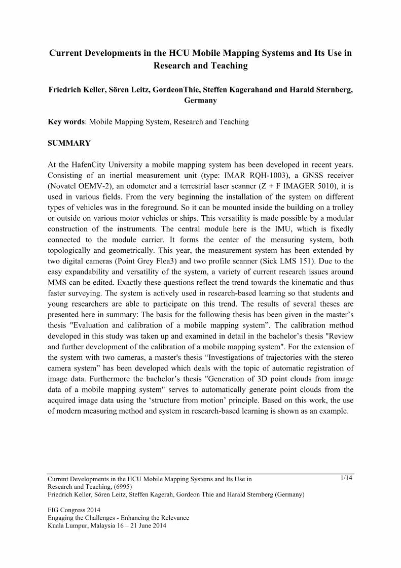
of MMS. Research and development of the system is fundamentally influenced and supported by the HCU students. They especially focus on the development of the implementation outside of buildings, cf. figure 1, left side.The aim here is to achieve that the system meets the state of the art in the MMS sector and to evaluate new sensors, software and work methods due to their degree theses.
Figure 1Concept for integration of the mobile mapping system
So the opportunity is given to students to participate in interesting and current research topics.At the same time it facilitates the research for the Ph.D. students. By involving the students into the learning research four degree theses have already been written.These works set the foundation of MMS and will be clarifiedlater on in this document. In chapter 2 sensors and construction of the platform will be explained initially. In the following two chapters the four degree theses will be divided into the chapters stereo camera system and calibration. 2. SENSORS By the use of sensors in research and education at the HCU, the MMS was developed and designed as a modular platform. The basis of the system is an aluminium plate of 1000x470x10 mm on which technical instruments can be attached. The modular construction does not only make it possible to attach and to remove instruments, but to integrate new sensors as well. This flexibility enables the system to be adapted to the special requirements of the potential survey area. The current research interest focuses on the application on a vehicle and on the application on a little trolley indoors (see figure 1, right side). In all application scenarios the core is a high-quality inertial measurement system (IMAR RQH 1003). This allows data recording of the different sensors (odometer- and GNSS-module) and
Current Developments in the HCU Mobile Mapping Systems and Its Use in Research and Teaching, (6995) Friedrich Keller, Sören Leitz, Steffen Kagerah, Gordeon Thie and Harald Sternberg (Germany) FIG Congress 2014 Engaging the Challenges - Enhancing the Relevance Kuala Lumpur, Malaysia 16 – 21 June 2014
4/14 Current
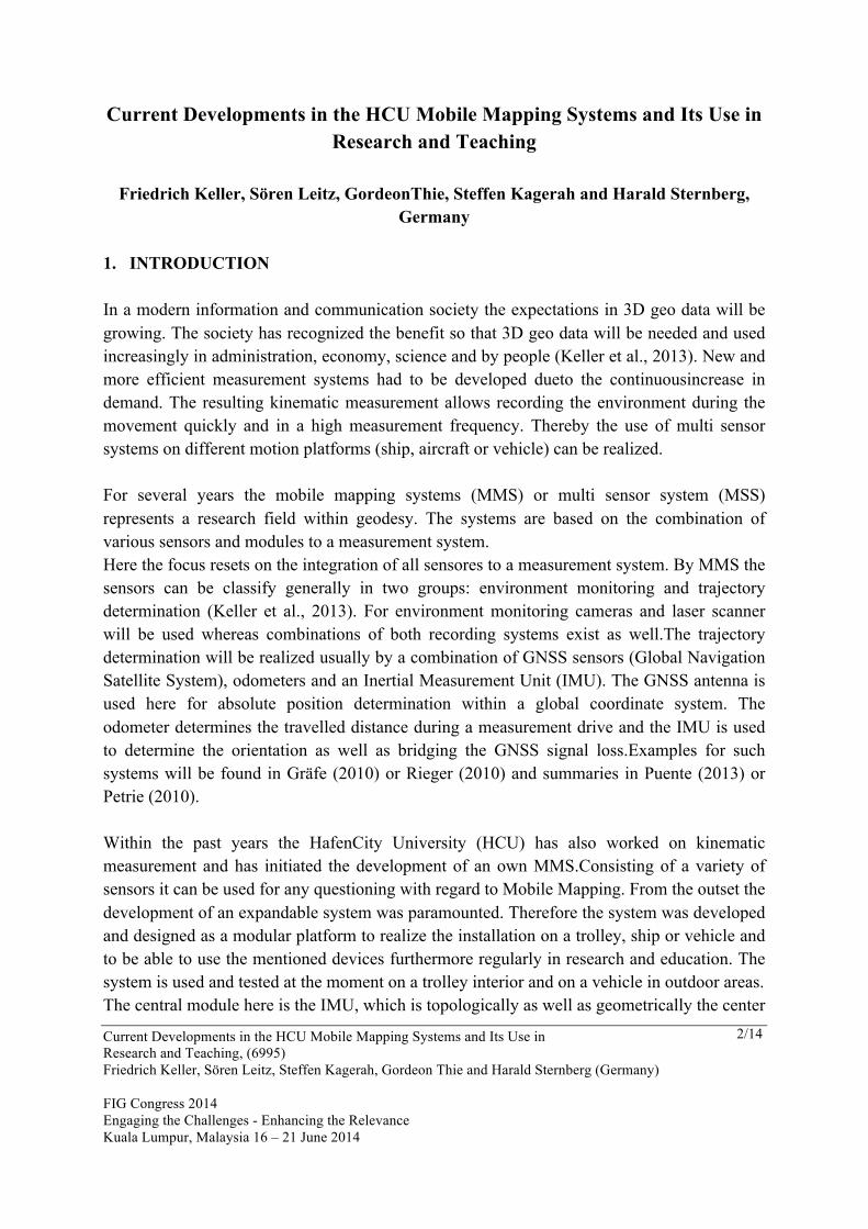
also the time synchronization of all sensors by synchronization signal (Pulse-per-second (PPS)). The IMU is topologically the central point of the system. This means that all other platform sensors are connected to it or are supplied by it with a synchronization signal. Through the fixed attachment to the platform the sensitive axes of the IMU forms simultaneously the coordinate system of the platform: the X-axis shows the driving direction, the Y-axis shows left and the Z-axis stands straight on the first mentioned axes. The position and the mounting angle of the other sensors will be defined in this system. Table 1 shows the variety of the currently used sensors.
Manufacturer Name „Classs of accuracy“
Inertiales Measurement System IMAR RQH 1003 0,003 deg/sqrt(h) (Navig. Grade) GNSS Novatel Receiver OEMV-2 Accuracy of kinem. GNSS
Leica AT502 Laserscanner Angle measurement Distance measurement Zoller + Fröhlich GmbH
ZF Imager 5010 0,0004 deg 1,2mm @ 50m
SICK LMC121 0,25 deg 12mm @ 50m Totalstation Leica TPS 1201+ 0,15 mgon 3mm + 1,5ppm Odometer Wachendorff WDG 58B 10000 I/U Peiseler Kfz-2000 2000 I/U Camera Point Grey 2x Flea3 Stereo 1,4 Megapixel
Table 1:Modulesof the sensor platform with class
of accuracy; manufacture’s data
For the applications and investigations described in the following chapters the system was configured for outdoor use. This configuration includes as basic equipment the IMU, as usual with MMS, the GNSS module, an odometer approved for road traffic and a laser scanner. Hereby the IMU records the inertial measurement data (angular rate and accelerations) of the system.The GNSS module will be tightly coupled with IMU and provides, besides derivable information like azimuth, the position and acceleration. The odometer measures the travelled distance. To enable a fusion of all measurement data it is necessary to know the lever arm to every sensor. These informationsare gained for sensors on a platform by a photogrammetric calibration. The calibration of the odometer position for vehicle-application must be carried
Current Developments in the HCU Mobile Mapping Systems and Its Use in Research and Teaching, (6995) Friedrich Keller, Sören Leitz, Steffen Kagerah, Gordeon Thie and Harald Sternberg (Germany) FIG Congress 2014 Engaging the Challenges - Enhancing the Relevance Kuala Lumpur, Malaysia 16 – 21 June 2014
5/14 Current
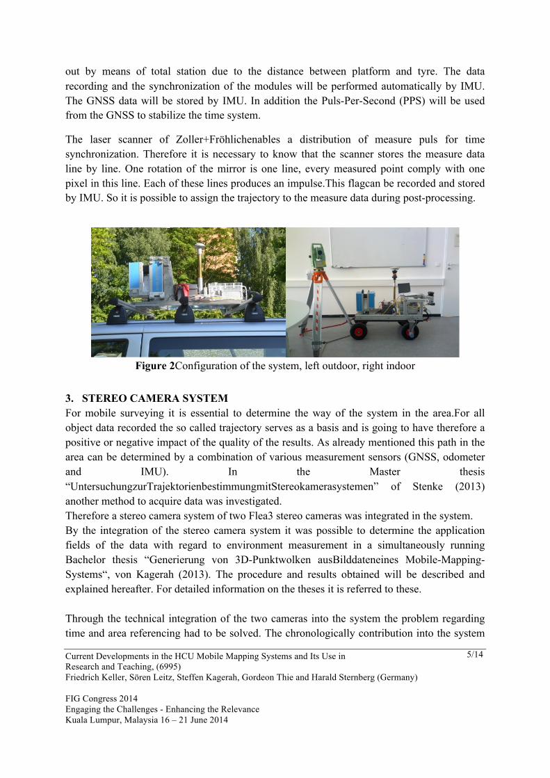
out by means of total station due to the distance between platform and tyre. The data recording and the synchronization of the modules will be performed automatically by IMU. The GNSS data will be stored by IMU. In addition the Puls-Per-Second (PPS) will be used from the GNSS to stabilize the time system.
The laser scanner of Zoller+Fröhlichenables a distribution of measure puls for time synchronization. Therefore it is necessary to know that the scanner stores the measure data line by line. One rotation of the mirror is one line, every measured point comply with one pixel in this line. Each of these lines produces an impulse.This flagcan be recorded and stored by IMU. So it is possible to assign the trajectory to the measure data during post-processing.
Figure 2Configuration of the system, left outdoor, right indoor
3. STEREO CAMERA SYSTEM For mobile surveying it is essential to determine the way of the system in the area.For all object data recorded the so called trajectory serves as a basis and is going to have therefore a positive or negative impact of the quality of the results. As already mentioned this path in the area can be determined by a combination of various measurement sensors (GNSS, odometer and IMU). In the Master thesis “UntersuchungzurTrajektorienbestimmungmitStereokamerasystemen” of Stenke (2013) another method to acquire data was investigated. Therefore a stereo camera system of two Flea3 stereo cameras was integrated in the system. By the integration of the stereo camera system it was possible to determine the application fields of the data with regard to environment measurement in a simultaneously running Bachelor thesis “Generierung von 3D-Punktwolken ausBilddateneines Mobile-Mapping-Systems“, von Kagerah (2013). The procedure and results obtained will be described and explained hereafter. For detailed information on the theses it is referred to these. Through the technical integration of the two cameras into the system the problem regarding time and area referencing had to be solved. The chronologically contribution into the system
Current Developments in the HCU Mobile Mapping Systems and Its Use in Research and Teaching, (6995) Friedrich Keller, Sören Leitz, Steffen Kagerah, Gordeon Thie and Harald Sternberg (Germany) FIG Congress 2014 Engaging the Challenges - Enhancing the Relevance Kuala Lumpur, Malaysia 16 – 21 June 2014
6/14 Current
is carried out by IMU. A connection of the two cameras with IMU makes it possible for PPT – (puls per time) or PPD (puls per distance) to send signals to both recording systems. Not only time allocation of the recordings is possible due to this signal, rather a simultaneously image capture is realized which means that the images can be processed as stereo images. The spatial referencing takes place by a photogrammetric approach with the camera itself. Hereby the camera detects control points which exist in a superior coordinate system.Because of the known position of the measurement systems and the control points it is possible to determine the coordinate center of the cameras (EL-Sheimy 2011). The exact knowledge of all coordinate centers allows the lever arm to calculate between these. During the post processingthe transformation of the single coordinate centers into a central coordinate system is realized by the lever arm.
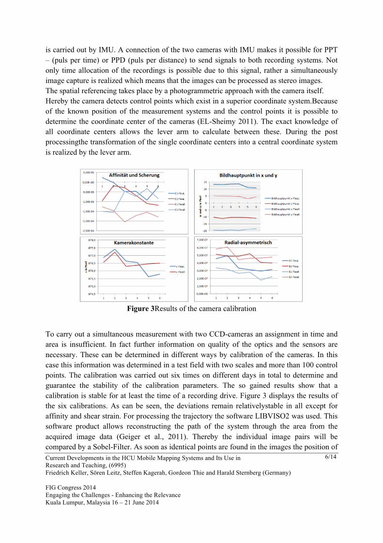
Figure 3Results of the camera calibration
To carry out a simultaneous measurement with two CCD-cameras an assignment in time and area is insufficient. In fact further information on quality of the optics and the sensors are necessary. These can be determined in different ways by calibration of the cameras. In this case this information was determined in a test field with two scales and more than 100 control points. The calibration was carried out six times on different days in total to determine and guarantee the stability of the calibration parameters. The so gained results show that a calibration is stable for at least the time of a recording drive. Figure 3 displays the results of the six calibrations. As can be seen, the deviations remain relativelystable in all except for affinity and shear strain. For processing the trajectory the software LIBVISO2 was used. This software product allows reconstructing the path of the system through the area from the acquired image data (Geiger et al., 2011). Thereby the individual image pairs will be compared by a Sobel-Filter. As soon as identical points are found in the images the position of
Current Developments in the HCU Mobile Mapping Systems and Its Use in Research and Teaching, (6995) Friedrich Keller, Sören Leitz, Steffen Kagerah, Gordeon Thie and Harald Sternberg (Germany) FIG Congress 2014 Engaging the Challenges - Enhancing the Relevance Kuala Lumpur, Malaysia 16 – 21 June 2014
7/14 Current
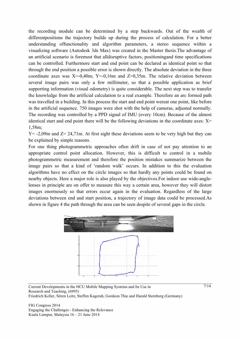
the recording module can be determined by a step backwards. Out of the wealth of differentpositions the trajectory builds up during the process of calculation. For a better understanding offunctionality and algorithm parameters, a stereo sequence within a visualizing software (Autodesk 3ds Max) was created in the Master thesis.The advantage of an artificial scenario is foremost that alldisruptive factors, positioningand time specifications can be controlled. Furthermore start and end point can be declared as identical point so that through the end position a possible error is shown directly. The absolute deviation in the three coordinate axes was X=-0,40m; Y=-0,16m and Z=0,35m. The relative deviation between several image pairs was only a few millimeter, so that a possible application as brief supporting information (visual odometry) is quite considerable. The next step was to transfer the knowledge from the artificial calculation to a real example. Therefore an arc formed path was travelled in a building. In this process the start and end point wereat one point, like before in the artificial sequence. 750 images were shot with the help of cameras, adjusted normally. The recording was controlled by a PPD signal of IMU (every 10cm). Because of the almost identical start and end point there will be the following deviations in the coordinate axes: X= 1,58m; Y= -2,09m und Z= 24,71m. At first sight these deviations seem to be very high but they can be explained by simple reasons. For one thing photogrammetric approaches often drift in case of not pay attention to an appropriate control point allocation. However, this is difficult to control in a mobile photogrammetric measurement and therefore the position mistakes summarize between the image pairs so that a kind of ‘random walk’ occurs. In addition to this the evaluation algorithms have no effect on the circle images so that hardly any points could be found on nearby objects. Here a major role is also played by the objectives.For indoor use wide-angle-lenses in principle are on offer to measure this way a certain area, however they will distort images enormously so that errors occur again in the evaluation. Regardless of the large deviations between end and start position, a trajectory of image data could be processed.As shown in figure 4 the path through the area can be seen despite of several gaps in the circle.
Current Developments in the HCU Mobile Mapping Systems and Its Use in Research and Teaching, (6995) Friedrich Keller, Sören Leitz, Steffen Kagerah, Gordeon Thie and Harald Sternberg (Germany) FIG Congress 2014 Engaging the Challenges - Enhancing the Relevance Kuala Lumpur, Malaysia 16 – 21 June 2014
8/14 Current
Figure 4Top: field of view form the camera, bottom: trajectory form the images
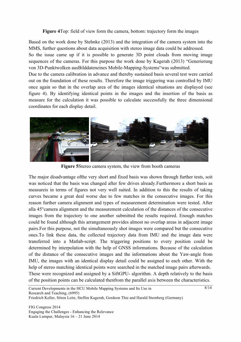
Based on the work done by Stehnke (2013) and the integration of the camera system into the MMS, further questions about data acquisition with stereo image data could be addressed. So the issue came up if it is possible to generate 3D point clouds from moving image sequences of the cameras. For this purpose the work done by Kagerah (2013) “Generierung von 3D-Punktwolken ausBilddateneines Mobile-Mapping-Systems“was submitted. Due to the camera calibration in advance and thereby sustained basis several test were carried out on the foundation of these results. Therefore the image triggering was controlled by IMU once again so that in the overlap area of the images identical situations are displayed (see figure 4). By identifying identical points in the images and the insertion of the basis as measure for the calculation it was possible to calculate successfully the three dimensional coordinates for each display detail.
Figure 5Stereo camera system, the view from booth cameras
The major disadvantage ofthe very short and fixed basis was shown through further tests, soit was noticed that the basis was changed after few drives already.Furthermore a short basis as measureis in terms of figures not very well suited. In addition to this the results of taking curves became a great deal worse due to few matches in the consecutive images. For this reason further camera alignment and types of measurement determination were tested. After alla 45°camera alignment and the measurement calculation of the distances of the consecutive images from the trajectory to one another submitted the results required. Enough matches could be found although this arrangement provides almost no overlap areas in adjacent image pairs.For this purpose, not the simultaneously shot images were compared but the consecutive ones.To link these data, the collected trajectory data from IMU and the image data were transferred into a Matlab-script. The triggering positions to every position could be determined by interpolation with the help of GNSS informations. Because of the calculation of the distance of the consecutive images and the informations about the Yaw-angle from IMU, the images with an identical display detail could be assigned to each other. With the help of stereo matching identical points were searched in the matched image pairs afterwards. These were recognized and assigned by a SiftGPU- algorithm. A depth relatively to the basis of the position points can be calculated thenfrom the parallel axis between the characteristics.
Current Developments in the HCU Mobile Mapping Systems and Its Use in Research and Teaching, (6995) Friedrich Keller, Sören Leitz, Steffen Kagerah, Gordeon Thie and Harald Sternberg (Germany) FIG Congress 2014 Engaging the Challenges - Enhancing the Relevance Kuala Lumpur, Malaysia 16 – 21 June 2014
9/14 Current
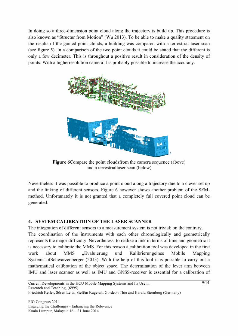
In doing so a three-dimension point cloud along the trajectory is build up. This procedure is also known as “Structur from Motion” (Wu 2013). To be able to make a quality statement on the results of the gained point clouds, a building was compared with a terrestrial laser scan (see figure 5). In a comparison of the two point clouds it could be stated that the different is only a few decimeter. This is throughout a positive result in consideration of the density of points. With a higherresolution camera it is probably possible to increase the accuracy.
Figure 6Compare the point cloudsfrom the camera sequence (above)
and a terrestriallaser scan (below)
Nevertheless it was possible to produce a point cloud along a trajectory due to a clever set up and the linking of different sensors. Figure 6 however shows another problem of the SFM-method. Unfortunately it is not granted that a completely full covered point cloud can be generated. 4. SYSTEM CALIBRATION OF THE LASER SCANNER The integration of different sensors to a measurement system is not trivial; on the contrary. The coordination of the instruments with each other chronologically and geometrically represents the major difficulty. Nevertheless, to realize a link in terms of time and geometric it is necessary to calibrate the MMS. For this reason a calibration tool was developed in the first work about MMS „Evaluierung und Kalibrierungeines Mobile Mapping Systems”ofSchwarzenberger (2013). With the help of this tool it is possible to carry out a mathematical calibration of the object space. The determination of the lever arm between IMU and laser scanner as well as IMU and GNSS-receiver is essential for a calibration of
Current Developments in the HCU Mobile Mapping Systems and Its Use in Research and Teaching, (6995) Friedrich Keller, Sören Leitz, Steffen Kagerah, Gordeon Thie and Harald Sternberg (Germany) FIG Congress 2014 Engaging the Challenges - Enhancing the Relevance Kuala Lumpur, Malaysia 16 – 21 June 2014
10/14
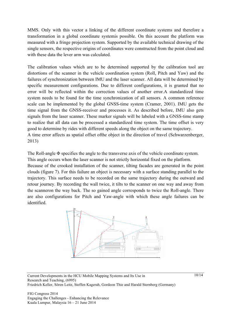
MMS. Only with this vector a linking of the different coordinate systems and therefore a transformation in a global coordinate systemis possible. On this account the platform was measured with a fringe projection system. Supported by the available technical drawing of the single sensors, the respective origins of coordinates were constructed from the point cloud and with these data the lever arm was calculated. The calibration values which are to be determined supported by the calibration tool are distortions of the scanner in the vehicle coordination system (Roll, Pitch and Yaw) and the failures of synchronization between IMU and the laser scanner. All data will be determined by specific measurement configurations. Due to different configurations, it is granted that no error will be reflected within the correction values of another error.A standardized time system needs to be found for the time synchronization of all sensors. A common reference scale can be implemented by the global GNSS-time system (Cramer, 2001). IMU gets the time signal from the GNSS-receiver and processes it. As described before, IMU also gets signals from the laser scanner. These marker signals will be labeled with a GNSS-time stamp to realize that all data can be processed a standardized time system. The time offset is very good to determine by rides with different speeds along the object on the same trajectory. A time error affects as spatial offset ofthe object in the direction of travel (Schwarzenberger, 2013) The Roll-angle Φ specifies the angle to the transverse axis of the vehicle coordinate system. This angle occurs when the laser scanner is not strictly horizontal fixed on the platform. Because of the crooked installation of the scanner, tilting facades are generated in the point clouds (figure 7). For this failure an object is necessary with a surface standing parallel to the trajectory. This surface needs to be recorded on the same trajectory during the outward and retour journey. By recording the wall twice, it tilts to the scanner on one way and away from the scanneron the way back. The so gained angle corresponds to twice the Roll-angle. There are also configurations for Pitch and Yaw-angle with which these angle failures can be identified.
Current Developments in the HCU Mobile Mapping Systems and Its Use in Research and Teaching, (6995) Friedrich Keller, Sören Leitz, Steffen Kagerah, Gordeon Thie and Harald Sternberg (Germany) FIG Congress 2014 Engaging the Challenges - Enhancing the Relevance Kuala Lumpur, Malaysia 16 – 21 June 2014
11/14
Figure 7Effects of a faulty Roll-angle. Recording of an object with two rides on the sametrajectorywith same speed (according to Keller and Sternberg, (2013)).
The RANSAC-algorithm is used to solve the offset search. He is not using any of the classical equalization for the smallest squares over the entire data record, but uses random chosen data points to calculate the model. In this process is always the minimum of the number of points used, which are necessary to describe the model (e.g. two points in case of a straight line). The process runs iteratively therefore the steps will be repeated several times. The amount of iterations depends on the model to be determined, the size and the estimated share of outlier of the data record. Finally the biggest consensus set for compensation of the model after the smallest squares is used. This procedure is working with any mathematically models as forlevelling or sphere fittingin fade away laser scan data. A stable calibration of the whole system is not only of significantimportance for the object registration but for futher works and developments too. This is the reason why also another Bachelor’s thesis with the title „Überprüfung und Weiterentwicklung der Kalibrierungeines Mobile Mapping Systems” byLeitz and Thie (2013) addresses the subject calibration of the single components of MMS. This work is based directly on the before mentioned Master’s thesis ofSchwarzenberger, (2012) and treats among others the main emphasis:precise examination of calibration, deformation analysis of the platform, photogrammetric measurement and calibration via an object space. The first named point, precise examination, provides here the basis for the actual calibration. The calibration of a mobile mapping system respectively their investigation needs guidelines and limits with regard to the gained and expectedprecision. Here the precision of the calibration depends directly on the required precision of the points recorded via laser scanner.For this purpose, threshold values will be determined for the standard deviation of the measured points and conclusions will be drawn on the incoming standard deviations of the calibration parameter with the support of variance propagation. The variance propagation contains all parameter from a measured point up to its coordinate determination in the GPS-system. A deformation analysis of the platform was carried out because of the different fields of application on the vehicle, ship, trolley etc. The system is hereby fixed in different ways and will be configured differently by what the weight distribution and the surface will change. That the platform twists or bends can be a result by which the installed components change their position to another and will influence the calibrations. The investigations of this problem were made by photogrammetric measurement in several epochs and allow conclusions to be drawn about possible movement from 0,08 mm. With the support of photogrammetric measurement the lever arm was also determined between IMU and scanner and between IMU and GPS-antenna. For the purpose of control and comparison the calibration angles were also determined by photogrammetric measurement and compared with the results of calibration by
Current Developments in the HCU Mobile Mapping Systems and Its Use in Research and Teaching, (6995) Friedrich Keller, Sören Leitz, Steffen Kagerah, Gordeon Thie and Harald Sternberg (Germany) FIG Congress 2014 Engaging the Challenges - Enhancing the Relevance Kuala Lumpur, Malaysia 16 – 21 June 2014
12/14
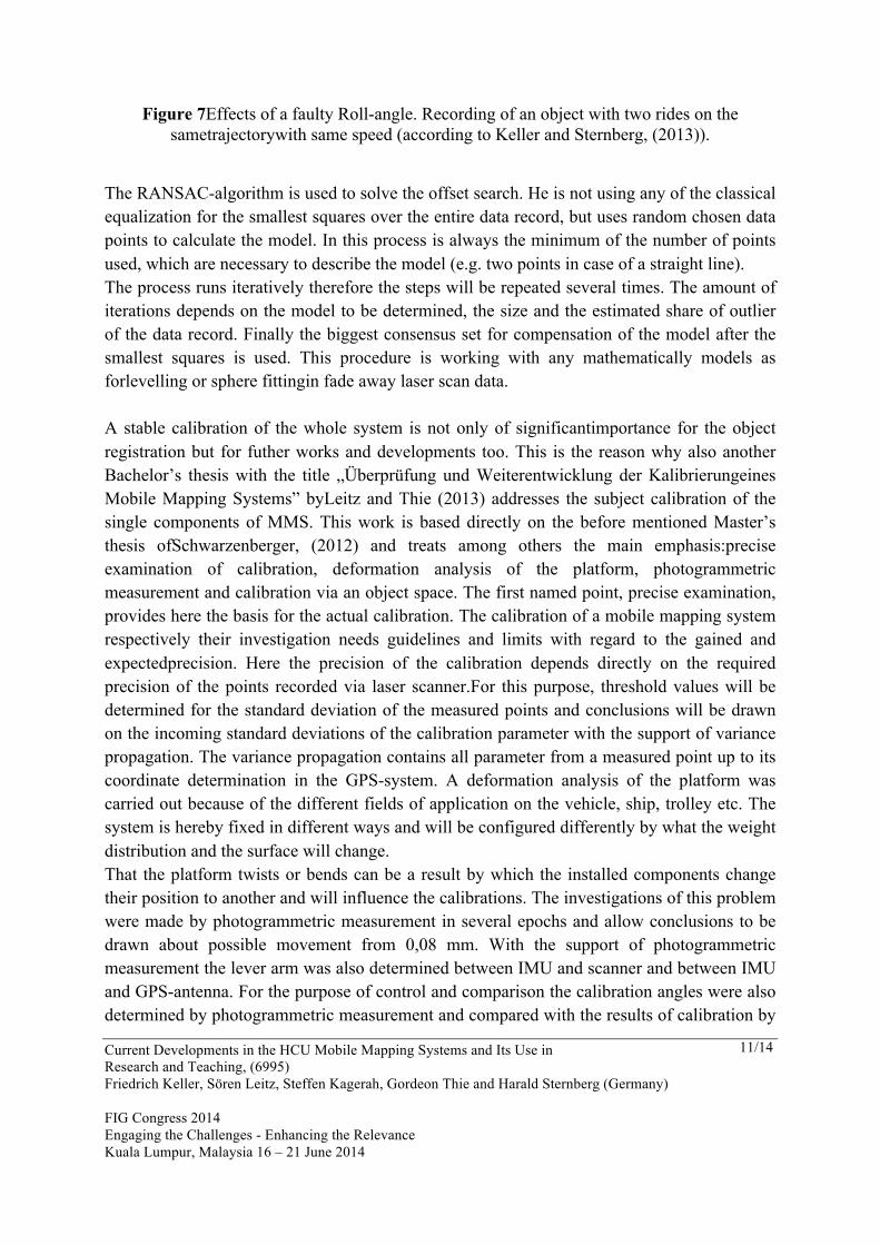
object space. The calibration on the basis of the measured object data from the laser scanner were performed according to the method developed by Schwarzenberger (2012) and the appropriate calibration tools and examined on its stability and reliability. Because of the numerous test measurements and attempts it should be possible to detect and solve any inadequacy and problems of the procedure. Hereby, two substantial core statements can be noted as result. Firstly, that the calibration tools provide usable solutions but also that the calibration by an object space stands and falls with the quality of the trajectory. As described before, the calibration parameter will be determined from the point clouds of several drives. These point clouds of the same object can show deviations to one another should the trajectory achieve only inadequate solutions. There is no need to say that this has a direct impact on the investigations of the calibration parameter and can lead to seriously distorted results. With this knowledge, the direction of further works is given instantly.The purpose of these works should be amore reliable and GNSS-independent trajectory determination, to be able to counteract problematic shading in urban areas and also to improve the indoor use continuously.Potential is also given with the further development and automation of the calibration tools.The aim would be here an easy to understand and user-friendly operation, so that MMS can be implemented by the user without intensive preparation.
Figure 8Pointcloud from the mobile mapping system in Hamburg
5. CONCLUSION AND OUTLOOK The aim of HCU is to give students the opportunity to contribute to current research topic. As mentioned in the introduction the kinematic survey by mobile mapping system is treated as
Current Developments in the HCU Mobile Mapping Systems and Its Use in Research and Teaching, (6995) Friedrich Keller, Sören Leitz, Steffen Kagerah, Gordeon Thie and Harald Sternberg (Germany) FIG Congress 2014 Engaging the Challenges - Enhancing the Relevance Kuala Lumpur, Malaysia 16 – 21 June 2014
13/14
such. The four works presented here deal with sections of these measurement systems. Two of the works deal with the stereo camera system and the questioning to what extent they can be used as navigation or image sensor. The other two works refer more to the subject of navigation via GNSS and INS and the recording via laser scanner. Here the main focus was especially on the partial aspect of the system calibration as well as the development of work processes. Summarizing it can be stated that a functional mobile mapping system was developed by students. This system still has its weaknesses and does not comply entirely with the state of the art which is only due to the fact of the time limit of the theses. So the system is still very depending on the GNSS solution of the trajectory. For this reason one of the next issues for a thesis is the linking of the image data with the navigation module so that also control points in the area can be included into the trajectory. The aim is to increase the productivity and the easy operation of the measurement system to such an extent that the application in teaching is no longer limited to the theses but that the system can also be used in lower (Bachelor?) semesters. Thus, the HCU will move a further aspect of research in the focus of the students. REFERENCES Cramer, M. (2001): Genauigkeitsuntersuchungen zur GPS/INSIntegration in der Aerophotogrammetrie. Dissertation. Universität Stuttgart, Stuttgart. url.: http://elib.uni-stuttgart.de/opus/volltexte/2006/2718/pdf/Cramer_Diss.pdf El-Sheimy, N. (2011): Land-based MMT: State of the Art and Future Trends. In: Proceedings of The 7th International Symposium on Mobile Mapping Technology. (7th MMT 2011). Cracow, Poland, June 13-16. Geiger, A., Ziegler J. und Stiller C. (2011). StereoScan: Dense 3dReconstruction in Real-time. In: IEEE Intelligent Vehicles Symposium. Baden-Baden und Germany. url: http://www.cvlibs.net/publications/iv11.pdf Gräfe, G. (2011): High precision kinematic 3D Engineering Surveying Applications using multiple scanners and cameras. In: Proceedings of The 7th International Symposium on Mobile Mapping Technology. (7th MMT 2011). Cracow, Poland, June 13-16. Kagerah, S. (2013): Generierung von 3D Punktwolken aus Bilddaten eines Mobile Mapping Systems. Bachelorthesis (unpublished).HafenCityUniversität, Hamburg. Keller, F., Sternberg, H. (2013): Multi-Sensor Platform for Indoor Mobile Mapping: System
Current Developments in the HCU Mobile Mapping Systems and Its Use in Research and Teaching, (6995) Friedrich Keller, Sören Leitz, Steffen Kagerah, Gordeon Thie and Harald Sternberg (Germany) FIG Congress 2014 Engaging the Challenges - Enhancing the Relevance Kuala Lumpur, Malaysia 16 – 21 June 2014
14/14
Calibration and Using a Total Station for Indoor Applications. In: Remote Sensing Leitz, S. und Thie, G. (2013): Überprüfung und Weiterentwicklung der Kalibrierung eines Mobile Mapping Systems. Bachelorthesis (unpublished). HafenCity Universität, Hamburg. Petrie, G. (2010): An Introduction to the Technology Mobile Mapping Systems. In:Geoinformatics 13 (1), S. 32–42. Puente, I.; González-Jorge, H.; Martínez-Sánchez, J.; Arias, P. (2013): Review of mobile mapping and surveying technologies. In: Measurement 46 (7), S. 2127–2145. Rieger, P.; Studnicka, N.; Pfennigbauer, M.; Zach, G. (2010): Boresight alignment method for mobile laser scanning systems. In: Journal of Applied Geodesy 4 (1). Schwarzenberger, J. (2013): Evaluierung und Kalibrierung eines Mobile Mapping Systems. Masterthesis (unpublished). HafenCity Universität, Hamburg. Stenke, N. (2013): Untersuchungen zur Trajektorieenbestimmung mit Stereokamerasystemen. Masterthesis (unpublished). HafenCityUniversität, Hamburg. Wu, C. (2013), "Towards Linear-time Incremental Structure from Motion", 3DV 2013 CONTACTS Title Given name and family name HafenCityUniversität Hamburg Überseeallee 16 20457 Hamburg Germany Tel. +49 40 428 27 - 5391 Email: [email protected] Web site: www.hcu-hamburg.de