culligan - fermilab
TRANSCRIPT
CULLIGAN®
Smart Controller (GBE)For Commercial and Industrial Softener and Filter Applications
Models from 2011Firmware Version 2.1.3
©2011 Culligan International Com pa ny
Installation, Operation, and
Service Instructions with Parts Lists
Printed in USA
Cat. No. 01021161
Rev. H 01/10/11DCO # 012139

Attention Culligan Customer:Your local independently operated Culligan dealer employs trained service and maintenance personnel who are experienced in the installation, function and repair of Culligan equipment. This publication is written specifically for these individuals and is intended for their use.
We encourage Culligan users to learn about Culligan products, but we believe that product knowledge is best obtained by consulting with your Culligan dealer. Untrained individuals who use this manual assume the risk of any resulting property damage or personal injury.
WARNING! Electrical shock hazard! Prior to servicing equipment, disconnect power supply to prevent electrical shock.
WARNING! If incorrectly installed, operated, or maintained, this product can cause severe injury. Those who install, operate, or maintain this product should be trained in its proper use, warned of its dangers, and should read the entire manual before attempting to install, operate, or maintain this product. Failure to comply with any warning or caution that results in any damage will void the warranty.
CAUTION! This product is not to be used by children or persons with reduced physical, sensory or mental capabilities, or lack of experience or knowledge, unless they have been given supervision or instruction.
CAUTION! Children should be instructed not to play with this appliance.
CAUTION! If the power cord from the transformer to the unit looks or becomes damaged, the cord and transformer should be replaced by a Culligan Service Agent or similarly qualified person in order to avoid a hazard.
WARNING! This device complies with Part 15 of the FCC rules subject to the two following conditions: 1) This device may not cause harmful interference, and 2) This device must accept all interference received, including interference that may cause undesired operation.
This equipment complies with Part 15 of the FCC rules. Any changes or modifications not expressly approved by the manufacturer could void the user’s authority to operate the equipment. Changes or modifications not expressly approved by the party responsible for compliance could void the user’s authority to operate the equipment.
CAUTION! To reduce the risk of fire, use only No. 26 AWG or larger telecommunications line cord.
NOTE This system is not intended for use with water that is microbiologically unsafe or of unknown quality.
NOTE Check with your public works department for applicable local plumbing and sanitation codes. Follow local codes if they differ from the standards used in this manual. To ensure proper and efficient operation of the Culligan equipment to your full satisfaction, carefully follow the instructions in this manual.
Products manufactured and marketed by Culligan International Company (Culligan) and its affiliates are protected by patents issued or pending in the United States and other countries. Culligan reserves the right to change the specifications referred to in this literature at any time without prior notice. Culligan, Aqua-Sensor, Tripl-Hull, and SoftMinder are trademarks of Culligan International Company or its affiliates.
Culligan International Company
9399 West Higgins Road, Suite 1100 Rosemont, Illinois 60018
1-847-430-2800
www.culligan.com

Contents iCat. No. 01021161
Installation, Operation,
and Service Instructions with
Parts List
Culligan® Smart Controller (GBE)For Commercial and Industrial Softener and Filter Applications Models from 2011 Firmware Version 2.1.3
ContentsIntroduction ........................................................................ 1
Smart Controller Features ................................................. 2
Basic Principles ................................................................. 4
Operation ........................................................................... 5
Installation ......................................................................... 6
Smart Controller Circuit Board Layout ............................. 10
Smart Controller Programming ........................................ 14
Navigating the Menus and Keypad.................................. 15
First Time Set Up ............................................................. 19
Customizing Set Up ......................................................... 22
Softener and Filter Program Log ..................................... 29
Installing Accessories ...................................................... 30
Service and Maintenance ................................................ 69
Manual Regeneration ...................................................... 71
Manual Cycling ................................................................ 72
Error and Alert Codes ...................................................... 73
Diagnostic Screens.......................................................... 75
Menu Overview................................................................ 82
Smart Controller (GBE) Parts and Accessories ............... 86
Appendix A Programming Examples............................. 87
Appendix B Data Port Output........................................ 92
Appendix C Flow Device K-Factor Data .......................... 97
Culligan® Softener and Filter Program Log .................... 98
Index ............................................................................... 99

ii Culligan® Smart Controller (GBE) for Softeners and Filters ii Cat. No. 01021161
Document Change History DCO Chapter Description Reason
012139 Programming Updated menu selections and structure FWR 2.1.3

Introduction 1Cat. No. 01021161
Introduction
Read this Manual FirstBefore you operate the Culligan Smart Controller (GBE), read this manual to become familiar with the device and its capabilities.
About this ManualThis manual:
• Familiarizes the operator with the equipment
• Explains installation and setup procedures
• Provides basic programming information
• Explains the various modes of operation
• Gives specifications and troubleshooting information
Safe PracticesThroughout this manual there are paragraphs set off by special headings.
NoticeNotice is used to emphasize installation, operation or maintenance information which is important, but does not present any hazard. For example,
NOTICE The nipple must extend no more than 1 inch above the cover plate.
CautionCaution is used when failure to follow directions could result in damage to equipment or property. For example,
CAUTION! Disassembly while under water pressure can result in flooding.
WarningWarning is used to indicate a hazard which could cause injury or death if ignored. For example,
WARNING! Electrical shock hazard! Unplug the unit before removing the timer mechanism or cover plates!
The CAUTION and WARNING paragraphs are not meant to cover all possible conditions and situations that may occur. It must be understood that common sense, caution, and careful attention are conditions which cannot be built into the equip-ment. These MUST be supplied by the personnel installing, operating, or maintaining the system.
Be sure to check and follow the applicable plumbing codes and ordinances when installing this equipment. Local codes may prohibit the discharge of sanitizing or descaling solutions to drain.
Use protective clothing and proper face or eye protection equipment when handling chemicals or power tools.
NOTE The Culligan Smart Controller (GBE) is not intended for use with water that is microbiologically unsafe or of unknown quality without adequate disinfection either before or after the system.
NOTE Check with your public works department for applicable local plumbing and sanitation codes. Follow local codes if they differ from the standards used in this manual. To ensure proper and efficient operation of the Culligan Smart Controller (GBE) to your full satisfaction, carefully follow the instruc-tions in this manual.

2 Culligan® Smart Controller (GBE) for Softeners and Filters 2 Cat. No. 01021161
Smart Controller Features
The primary function of the Culligan Smart Controller (GBE) is to initiate and control the regeneration process via methods that are most convenient and cost effective for the customer while offering many operational features and benefits. The controller is designed to operate a wide range of existing and new softener and filtration valves.
Take Control of Your System and Your ProductivityThe Culligan Smart Controller (GBE) is an advanced design engineered to handle regeneration and monitoring of your water treatment equipment. It offers powerful programming options that can be used to operate and monitor any softener or filter system. It also provides sensing capabilities, expanded communications and a multifunction keypad—all in one simple-to-use unit.
Smart Controller FeaturesFeature Use/Benefit
Advanced Lighted OLED Display The user is guided through brightly lit graphical menu screens with clear, multi-line, full text prompts. See Figure 1.
Membrane Keypad The keypad uses sealed contacts for programming. No buttons to get dirty. See Figure 1.
Program Beeper Emits an audible beep when keys are depressed to help identify valid (short beep) or invalid (three short beeps) pushes. Can be enabled or disabled.
Power Source Electrical power required is 24 Volt 50/60 Hz AC current. A UL listed plug-in transformer (120V/24V) is provided.
Time of Day Displays current time of day in either 12-hour or 24-hour format. Real Time Clock with a Five-Year Battery Back-up
Keeps accurate time even during a power outage. Updates automatically when the GBE is equipped with optional modem capability.
English or Metric Values Displays can be set to either English or Metric units. Regeneration Interval Provides the ability to initiate a time clock regeneration based on a number
of days (1–99) or a specific day of the week. Regeneration Start Delay Allows a user determined number of hours (0-9) to be set for the purpose
of increasing the amount of time between regenerations in a multi unit installation.
Auxiliary Input Capable of accepting a remote signal from a dry contact device such as an operator push button for the purpose of initiating a regeneration sequence or external alarm signal.
Auxiliary Output on Alarm Capable of sending a signal when an alarm/error is recognized.
Figure 1. Smart Controller.
Figure 2. Remote display.

Smart Controller Features 3Cat. No. 01021161
Feature Use/BenefitExpansion Board for Additional Outputs • Control blocking valves.
• Control external solenoids or chemical feeders. Progressive Flow Trip Point and
Unbalanced Progressive Flow
Allows multiple tank systems operating with flow meters to bring tanks on-line or off-line as facility flow demands increase or decrease.
Multiple Unit Communication A communication cable interconnects multiple units to operate the controller in the Progressive Flow mode and prohibits them from regenerating at the same time.
Diagnostics The user can check the operation of sensors, progressive flow communica-tion, motor positions, or an optional wireless display.
Transformer is UL and CUL ListedRoHS Compliant
Optional Smart Controller FeaturesFeature Use/Benefit
Flow Meter/Sensor Input Supports various types of Hall effect flow sensors using a pro-grammable K factor to initiate a regeneration sequence.
Aqua-Sensor® Input Supports the patented digital Culligan Aqua-Sensor® technology used to efficiently initiate and control a regeneration sequence.
Telephone Modem • Calls in reports on regenerations and alarm conditions.
• Automatically updates time and date when calling in. Wireless Remote Display Displays the current status of the unit. It can be located up to 200
feet away from the GBE controller (depending on building and in-terference). The telephone modem can optionally be installed in the remote display. See Figure 2.
Smart Brine Tank Probe This probe monitors conditions inside the brine tank.
• Predicts when more salt is needed.
• Detects the presence of a salt bridge.
• Detects eductor line plugging.
• Signals brine tank overfilling condition.

4 Culligan® Smart Controller (GBE) for Softeners and Filters 4 Cat. No. 01021161
Basic Principles
What Is Hard Water?Water is said to be hard when it carries too high a concentration of calcium and magnesium. Acceptable water hardness levels will vary depending on the application.
Why Should Hardness Be Removed?Hard water causes scaling and etching which greatly impairs the life and efficiency of boilers, air-conditioning systems, cooling towers, water heaters, refrigeration plants and other equipment using water.
How Does It Work?The components of dissolved minerals are called ions. They carry either a positive or negative charge. Hardness ions of minerals dissolved in water carry a positive charge. These positively charged ions (cations) are attracted to a synthetic softening material called ion exchange resin.
The heart of the softening system, therefore, is a deep bed of resin which draws calcium and magnesium ions, as well as ferrous iron, from the water as it passes through the resin bed.
Can The Resin Draw Out Hardness Ions Indefinitely?No. During normal operation, the resin becomes saturated with positive ions and functions less efficiently. When hardness leakage occurs, the resin should be regenerated to restore its efficiency.
How Do You Regenerate Resin?You regenerate a resin bed by removing the mineral ions through a process called ion exchange. This regeneration pro-cess occurs in four steps and takes approximately 80 to 90 minutes.
BackwashDuring the backwash step, raw water flows rapidly upward (in reverse direction to the service flow) through the resin bed to expand the bed and flush out accumulated dirt, sediment and other sources of turbidity.
Brine DrawThe brine solution consisting of water and salt is drawn from a brine storage tank and allowed to flow slowly down through the resin bed. The brine solution removes the calcium and magnesium ions from the resin. This cycle can also be split into three “sub-cycles” which allow for the cost saving feature of brine reclaim.
Slow RinseBrine draw is then followed by a raw water slow rinse. This rinse step will slowly remove most of the remaining brine, exchanged calcium and magnesium ions from the resin. This cycle can also be split into three “sub-titles” which allow for the cost saving feature of brine reclaim.
Fast RinseSlow rinse is followed by a raw water flush, a very rapid down flow of raw water which removes the last traces of brine, and settles the resin bed.
How Often Must You Regenerate?Frequency must be determined for each installation based on the amount of water usage, its degree of hardness and the amount of resin through which it flows. In some cases it is necessary to utilize a resin cleaner when the raw water con-tains iron. Contact your local Culligan dealer for more information.
How Do You Control The Regeneration Process?The regeneration process for your commercial water softener is controlled automatically either on a predetermined time, volume, or external signal basis through the use of the Culligan GBE controller with optional flow sensor. See the Installa-tion chapter for further information. The regeneration process can also be initiated manually by the operator as required.

Operation 5Cat. No. 01021161
Operation
Modes of OperationTime Clock The Smart Controller (GBE) will initiate a regeneration based upon a time schedule of intervals of days (such as every three days) or on a specific day of week schedule (such as Mondays, Wednesdays and Saturdays). Because regenera-tion will occur at the prescribed schedule regardless of water use, this method is usually the most inefficient method of water softener operation.
Flow Meter/SensorWhen a flow meter or sensor is connected to the controller circuit board, the Smart Controller has the ability to measure the amount of water treated and initiate a regeneration sequence based upon the gallon capacity of the water treatment equipment. The controller can delay the regeneration signal until a convenient time of day (known as a delayed regenera-tion) or act and initiate the regeneration sequence as soon as the signal is received (known as immediate regeneration).
When installing an alternating duplex system (one tank on-line, the other in standby), only one flow measuring device is required to be installed in the common outlet header of the system. Parallel systems (multiple tank systems, all on-line simultaneously) require one flow device for each mineral tank in the system.
This method is a proven, cost-effective means to operate a water softening system.
Aqua-Sensor® (Softener use only)The Aqua-Sensor® detects when a softener resin bed has reached its point of exhaustion and, as a result, initiate a regen-eration sequence. This is the most cost-effective method of operation and may be combined with any of the operational modes previously described.
Progressive FlowThe Progressive Flow mode is used with up to six and as few as two mineral tanks in a system. It allows more than one tank in a system to either be on-line or off-line depending upon the downstream flow demand. If flow demand is greater than the flow capability of the tank on-line, another tank can be brought on-line to help satisfy the excess demand. Once the demand has decreased, the second tank is returned to a standby mode and the system reverts to just one tank on-line providing treated water.
The progressive flow mode of operation relies on a user programmable set point or Trip Point. The Trip Point is a unit of flow (gallons or liters) on a per minute basis. Once attained the trip point will cause the second unit (in multiple resin tank system) to come on-line. Each additional tank in the system will subsequently be brought on-line as multiples of the trip point are attained and remain in that state for ten seconds. (Example: a three-tank system with a trip point of 50 gpm will bring two tanks on-line once the facility flow demands is equal to or greater than the 50 gpm trip point. Should the flow demand reach 100 gpm or more, the third tank shall be brought on-line.)
Additional tanks will be returned to stand-by once the facility flow demand is: less than 95 percent of the trip point for two tank systems; less than 95 percent of two times (2X) the trip point for triplex systems; less than 95 percent of three times (3X) the trip point for quad systems; and remaining in that state for 30 seconds.
Utilizing the progressive flow feature may allow the owner to use smaller units, resulting in the potential for reduced capital and operation costs.
Unbalanced Progressive FlowSimilar to regular Progressive Flow, this mode is used when maximum and minimum flow rates have a wide fluctuation. In this mode you can have one tank that is smaller than the others. This tank has a separate Trip Point set so the Smart Controller knows what flow rate it can run at. The additional larger tanks are brought on-line when the trip point of the smaller tank is exceeded. The small tank is only online during low flow conditions. The small tank must be set up as the master tank.
Differential Pressure (Filters Only)When combined with an optional differential pressure device, the Culligan Smart Controller has the ability to initiate a backwashing sequence when the pressure differential across the media bed reaches a preset amount (usually 8–10 psi).
6 Culligan® Smart Controller (GBE) for Softeners and Filters 6 Cat. No. 01021161
Installation
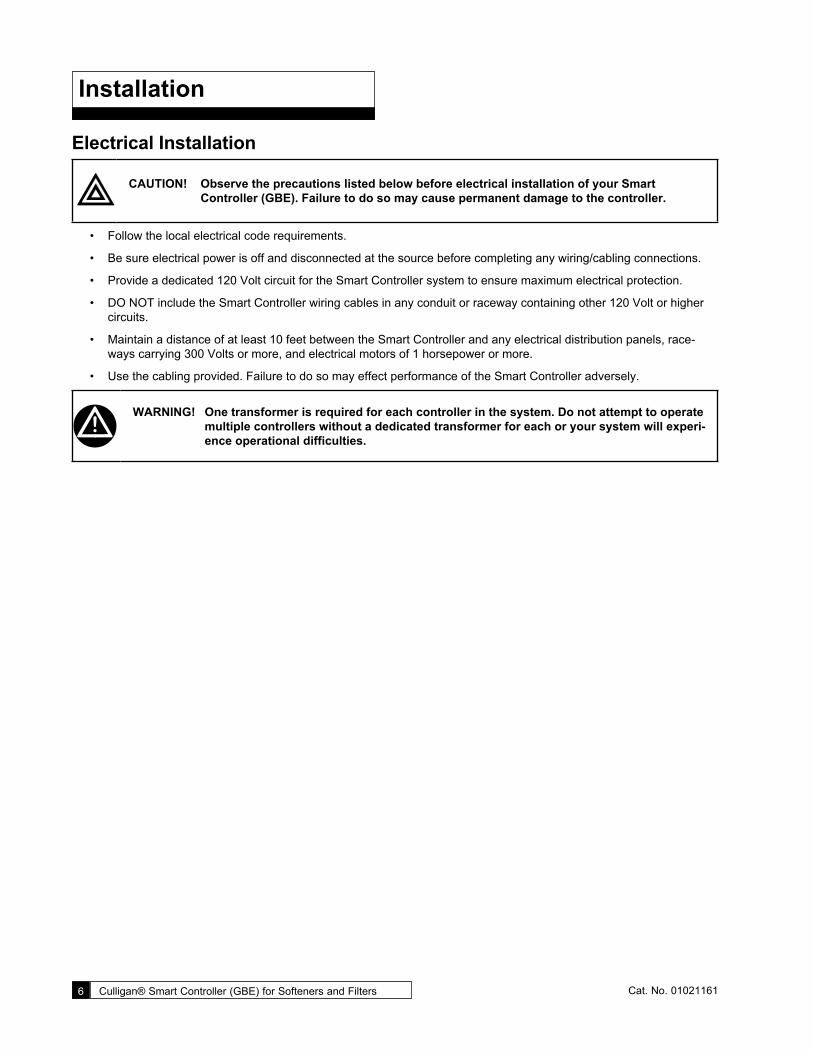
Electrical Installation
CAUTION! Observe the precautions listed below before electrical installation of your Smart Controller (GBE). Failure to do so may cause permanent damage to the controller.
• Follow the local electrical code requirements.
• Be sure electrical power is off and disconnected at the source before completing any wiring/cabling connections.
• Provide a dedicated 120 Volt circuit for the Smart Controller system to ensure maximum electrical protection.
• DO NOT include the Smart Controller wiring cables in any conduit or raceway containing other 120 Volt or higher circuits.
• Maintain a distance of at least 10 feet between the Smart Controller and any electrical distribution panels, race-ways carrying 300 Volts or more, and electrical motors of 1 horsepower or more.
• Use the cabling provided. Failure to do so may effect performance of the Smart Controller adversely.
WARNING! One transformer is required for each controller in the system. Do not attempt to operate multiple controllers without a dedicated transformer for each or your system will experi-ence operational difficulties.

Installation 7Cat. No. 01021161
Wiring Procedures and DiagramsPreparation
1. Loosen the screws or latches securing the controller access cover (see Figures 3 or 4) on each controller provided.
Figure 3.
Figure 4.
Figure 5.

8 Culligan® Smart Controller (GBE) for Softeners and Filters 8 Cat. No. 01021161
Cable RoutingAll input and output connections to the circuit board are 24 Volt or less.
Although the cables do not have to be run in conduit, it is necessary that long runs of cable be supported or protected by strapping them to the equipment piping. If conduit will be used to route the shielded cables, three factors must be consid-ered:
1. DO NOT share the same conduit or raceway with 120 Volt or higher circuits.
2. Keep cables at least six (6) inches away from 120 Volt or higher electrical circuits.
3. GROUND the conduit (if metallic) to a known “earth ground” location.
A series of holes are located on the sides of the Smart Controller (see Figures 6 and 7). Strain relief fittings are provided with the controller enclosure for interconnecting wiring. Install the plastic fittings as needed. Remove the compression nut and rubber sleeve from each fitting. Prior to connection of the cable wires to the circuit board, slide the compression nut and sleeve over the cable for the wiring connections. When wiring is completed, apply a small amount of silicone to the rubber sleeve and reassemble. This will assure all wiring is secure and assist in making the tightening of the fitting easier. Insert the plugs provided to block any holes not used for wiring or other accessories.
Right Side View
Brine Reclaim Solenoid (optional)
Input Connection for Flow Sensor
Output Connection for Remote Accessories
Input Connection for Remote Accessories
24 Volt Power Input Connection
Brine Reclaim Solenoid (optional)
Figure 6. Brine Refill Valve
Blocking Solenoid for Alternating Operation
Left Side View
Figure 7.

Installation 9Cat. No. 01021161
Smart Controller OverviewTo access the inside of the Smart Controller, refer to the instructions below.
CAUTION! Failure to complete the following steps might result in damage to the keypad or circuit board!
1. Loosen the front cover screw.
2. Hinge the front cover upwards. (See Figure 8). Do not remove the front cover yet.
3. Disconnect the keypad from the circuit board.
4. Remove the front cover.
CAUTION! Grip all connections to the circuit board by connecting terminals for assembly and disas-sembly. Failure to do so could result in dam-age to the wire leads or connecting terminals.
CAUTION! Do not touch any surfaces of the circuit board. Electrical static discharges may cause damage to the board. Handle the Smart Controller circuit board by holding only the edges of the circuit board. Keep replacement boards in their special anti-static bags until ready for use. Mishandling the circuit board will void the warranty.
5. The circuit board is held on with plastic posts. Push the locking clip at the end of the posts to allow the circuit board to be removed from the daughter board.
GBE CIRCUIT BOARD
AUXILIARY CIRCUIT BOARD
CIRCUIT BOARD BRACKETINTERFACE CIRCUIT BOARD
Figure 9. Locking clip.
CAUTION! Properly connect the wire connectors to the circuit board. The wires must exit the plug-in connector opposite of the raised white base of the circuit board connector.
CAUTION! Take extra care when connecting the 2.5 VAC and 24 VAC power. Failure to connect properly will result in damage to the circuit board.
Figure 8. Circuit board.

10 Culligan® Smart Controller (GBE) for Softeners and Filters 10 Cat. No. 01021161
Smart Controller Circuit Board Layout
Smart Controller Circuit Board Layout–Front
Figure 10. Smart Controller circuit board layout, front view.
Smart Controller Circuit Board Layout–Back
Aqua-SensorCable (Optional)
Power Cable(from transformer)
OptionalAlarm Relay BoardConnection (Aux 5)
Optional ModemConnections
Data PortPLC Output
RF BoardConnection(for remote)
Future UseDo Not ConnectAnything to these
Communication Cable(optional)
Motor Position CableMultiple Unit Jumper
Flow Meter Cable(optional)
Smart Brine TankCable (optional)
External regenerationsignal connection (optional)or external alarm
Motor Connection
Blocking ValveConnection (optional)Programmable
Outputs(optional)
POSITION DCMOTOR
FLOWMETER
RS485
BRINETANK
J22
2.5v 24v
AQU
A SEN
SOR
AUX OUT4AUX OUT3AUX OUT2AUX OUT1AUX INPUT
Figure 11. Smart Controller circuit board layout, rear view.
Keypad connector
Battery CR2032 (Postitive Side Up)
Pull protective tab before activating power to activate the battery
OLED Display

Smart Controller Circuit Board Layout 11Cat. No. 01021161
Smart Controller Circuit Board OutputsThe circuit board supports four outputs:
• Motor control (DC Motor)
• Blocking valve (Use Aux Out 4)
• Two programmable auxiliary outputs (Aux Out 2 and Aux Out 3) for commercial four-cycle and five-cycle valves.
• Controller interface (communication between multiple controllers) (RS485).
CAUTION! Connecting 24 V to the 2.5 V connection on the circuit board will damage the circuit board.
NOTE If you are using Aqua-Sensor®, you should run the 2.5 V wiring now as the cable is run through the same cord grip. See page 12 for details.
Wiring the Smart Controller Power Cord1. Locate the power cord among the controller parts. It has a white connector on one end and two spade connec-
tors on the other.
2. Locate the cord grip among the parts.
3. To assemble the power cord, first run the cord grip nut over the spade terminal end of the power cord.
4. Next, run the spade terminals through a hole in the side of the controller FROM THE INSIDE (see Figure 12).
5. Finally, run the cable through the bottom end of the cord grip, and assemble the grip to the controller wall.
6. Plug the board connector to the board where it is labeled 24 V. The connector has four (4) connections but only two wires are connected. The other end of the power cord (with spade terminals) should be connected to the two 24 VAC terminals on the transformer (see Figure 13).
CAUTION! DO NOT PLUG THE TRANSFORMER INTO THE WALL UNTIL ALL WIRING IS COMPLETED.
7. Repeat the process for any additional units in the system.
METAL TABSConnect to white connector on main power cord
If using Aqua-Sensor, plug metal tabs at end of cord into connector
Figure 12. 24 V Power Connection

12 Culligan® Smart Controller (GBE) for Softeners and Filters 12 Cat. No. 01021161
24 V Transformer The Smart Controller is powered by a 24 VAC/100 VA transformer. If there are multiple controls in the system being installed, each controller will require its own transformer. It is recommended that the transformer be plugged into a dedicated 120V circuit.
CAUTION! Connecting 24 V to the 2.5 V connection on the circuit board will damage the circuit board.
CAUTION! To eliminate the possibility of polarity issues, carefully follow the wiring details shown in Figure 13.
1. Connect one wire from the 24 V cable to the outermost 24 VAC transformer screw terminal (see Figure 13). The other end of the wire should be connected to one of the 24 V terminals on the Smart Controller circuit board (Figure 13) by way of the white connector.
2. Repeat the process for the other 24 V power supply wire attaching the second wire to the opposite terminal on the transformer and next to the other wire connected to the 24V pins on the Smart Controller board.
Figure 13. Transformer and Smart Controller circuit board.

Smart Controller Circuit Board Layout 13Cat. No. 01021161
Brine Refill Valve WiringNOTE This only applies to Culligan CSM Softeners.
Install the Solenoid Coil and Connector1. Locate the solenoid coil and connector cord.
2. Assemble it to the brine refill valve as shown in Figure 14.
Install the Cord Grip1. Remove the hole plug from the left side of the Smart
Controller enclosure.
2. Locate the cord grip fitting and nut.
3. Assemble them through the open hole and thread the solenoid coil cord through the cord grip fitting as shown in Figure 15.
4. Tighten the cord grip onto the cord.
Wire the Valve1. Wire the valve to Aux Out 2 as shown in the diagram
in Figure 16.
2. Trim the wires to a suitable length.
NOTE Remember to set the brine refill time when using the brine refill valve. It is set using Aux2. See page 47 for programming instructions.
SolenoidCoil
Screw PlasticSpacer
Figure 14.
Figure 15.
Figure 16.
2.5VACP9 Power
24VAC
VlvAux1Sol
P7Aux2
P8P5
CamP1 P10
SnsrAqua
Meter
P4Flow
In
P2Aux
LCD
TRIM OFFGREEN WIRE
BLACK
WHITE REFILLSOLENOID VALVE
CIRCUIT BOARDMVP

14 Culligan® Smart Controller (GBE) for Softeners and Filters 14 Cat. No. 01021161
Smart Controller Programming
Programming The programming process requires various types of data input. The following information pertains to calculating the soft-ening capacity of the water softening system.
Capacity SettingsThe capacity of a water softener is determined by two factors; resin amount and water chemistry.
Single Tank SystemsNormally a single tank system has enough resin capacity to soften water for a minimum period of 24 hours. Time of regen-eration is usually set to occur very early in the morning or at a time when no softened water is required. This is because when the softener is regenerating, hard water is typically bypassed through the system and into the facility if a demand for water if present.
If regeneration is desired at a time of day when there is no water usage then the system must have a “reserve” capacity which must last an entire day if the regeneration signal (time clock, Aqua-Sensor® and/or meter) occurs at the beginning of the day. Subtract this reserve capacity from the total capacity to determine capacity to signal.
NOTE If the reserve capacity is more than one-third (1/3) of the total capacity, a meter system may not reduce salt consumption relative to a timeclock system.
Multiple Tank SystemsMultiple tank systems offer the benefit of continuous soft water supply. When using the Aqua-Sensor® to initiate a regen-eration sequence, the system capacity may be set for the maximum amount the system is capable of producing. However multiple tank systems using only water meters and or time clock as the basis for regeneration initiation are recommended to be set up with a 10% reserve capacity. The purpose of the reserve capacity in multiple tank systems is to allow for subtle changes in water chemistry. You will be able to get the reserve capacity during programming.
Determining Batch Set PointTo determine the batch set point for programming the Culligan Smart Controller, use the following formula:
Total Capacity – Reserve Capacity
Hardness = Gallons
The Smart Controller will calculate this for you automatically. You can use the formula above to verify the setting.
For more information on programming multi-tank systems, see page 39.
Program Data InputThere are a few items to note that can make the programming of the Smart Controller a little easier. They are:
Slew Rates This term refers to the speed at which the display moves through the input of mate-rial. For example, holding down the up arrow key for five (5) seconds when inputting minutes for Time of Day will cause the minutes to pass in ten (10) minute blocks of time. Press the up arrow or down arrow keys for shorter periods (less than 5 seconds) will slow the rate. To move through the programming slowly, do not hold down the up arrow or the down arrow keys.
Beeper A beeper is available to assist the user by providing an audible tone (about 70 deci-bels) to signify valid (one beep) and invalid (three beeps) key presses. The beeper can be deactivated in the programming mode. (If error occurs, beep will still be ON even if set to “No” programming.)
Programming Mode Timeout If there is no keypad activity for a three (3) minute period while in the programming mode, the controller will exit the programming mode and return to the main display. Any setting that was changed prior to the control timing out will revert back the origi-nal value. Pressing the check mark key saves the setting.
Program Input Acceptance For programming information to be accepted, the check mark key must be depressed prior to programming mode timeout.

Navigating the Menus and Keypad 15Cat. No. 01021161
Navigating the Menus and Keypad
DOWN button
CHECK MARK or OK button
UP button
CANCEL (X) button
UP ARROW button: scrolls up the menu
Controller
Remote
DOWN ARROW button: scrolls down the menu
CHECK MARK button: selects the highlight-ed option, opens a new screen, or accepts a changed setting
CANCEL or EXIT button: returns to the pre-vious screen or cancels a changed setting
NOTE Hold down the or button to quickly scroll through the setting without repeatedly pressing the button.
SOFTENINGJAN-01-10 12:01P 1. This is the home screen. Press any key except to display the main menu.
>1)INFORMATION 2)MANUAL MODE 3)SET DATE/TIME 4)ACCESSORIES
2. This is the main menu. The cursor/pointer (>) shows where you are in the menu. Use or to scroll through the menu. The selection cursor scrolls down to the next line or displays the next screen.
3. Press to select the item next to the cursor. For example, press to select 3)SET DATE/TIME.

16 Culligan® Smart Controller (GBE) for Softeners and Filters 16 Cat. No. 01021161
SETMONTH JAN 4. The controller screen displays a setting title and value. Here we see the current
value for the month setting is January.
SETMONTH >JAN 5. Press to select the item. The screen displays a cursor next to the value. This
indicates that the value may be changed by pressing the or button.
SETMONTH >FEB
6. Press to select a new value. The screen displays the new setting value next to the cursor.
7. Press to select the next available value. You may press or to scroll through all available options for this setting.
SETMONTH FEB 8. Press to accept the selected screen value. The screen displays the value, no
longer preceded by the cursor.
SETDAY 1 9. Press to scroll to the next setting.
1)INFORMATION 2)MANUAL MODE>3)SET DATE/TIME 4)ACCESSORIES
10. Press to exit from the setting without saving changes. The screen displays the parent menu (such as the main menu).
SOFTENINGJAN-01-10 12:01P 11. Press to display the home screen.
NOTE Unplugging the Culligan water softener will not affect any of the control settings (the control must be plugged in for at least 15 minutes). Once programmed, the settings will be stored indefinitely.

Navigating the Menus and Keypad 17Cat. No. 01021161
Smart Controller ProgrammingThe programming for the Smart Controller is based on a menu structure. There are six top-level menus with additional op-tions in submenus. The top-level menus are:
1. INFORMATION
2. MANUAL MODE
3. SET DATE/TIME
4. ACCESSORIES
5. ADV. SETUP
6. DIAGNOSTICS
Here is a brief explanation of what you will find under each menu.
Menu/Submenu DescriptionInformation Scrolls through the operating information for the unit.Manual Mode Initiates a manual regeneration.Set Time and Date Sets or changes the time and/or date. This is initially done during first time set up.
This information is saved in memory even in the event of a power outage.Accessories Sets up any installed accessories. This includes Aqua-Sensor®, beeper, Aux In, Aux
Outputs, Smart Brine Tank sensor, Wireless Remote, Modem, Chlorinator, flow meter, service phoneline, and external filter.
Advanced Setup Customizes the unit settings. There are five sub-menus that offer customized settings.System Setup Customizes many of the initial setup information. Water Hardness, Iron, Salt Type,
Resin Type and Line Pressure are among the settings.Regeneration Setup Specifies custom salt dosage, reserve capacity, regeneration time and regeneration
mode.Cycle Times Specifies custom cycle times for the units.Regeneration Trigger Specifies custom regeneration triggers, the regeneration interval, predict mode and
days of regeneration.Diagnostics Performs diagnostics for sensors, wireless, progressive flow, motor control, data port,
phone line (modem), and displays advanced statistics.

18 Culligan® Smart Controller (GBE) for Softeners and Filters 18 Cat. No. 01021161
Typical Commercial SetupSetting up the Smart Controller for a commercial installation requires a few additional steps. Follow the outline below to make sure everything is covered.
1. Run the first time setup (see following page).
2. Set up accessories. These include:
• Aqua-Sensor®
• Beeper
• Aux In
• Aux Outs (needed for multi-tank, brine reclaim and refill on 4-cycle valves)
• Smart Brine Tank Sensor
• Wireless Remote
• Modem
• Alarm Relay
• Service Phone
• External Filter3. You must configure the controller differently for a multi-tank system. This is explained in the Customizing Setup
section.
4. If you are using immediate regeneration, you must change the Reserve Capacity setting under Advanced Setup/REGEN SETUP and the REGEN MODE.
5. Set/Review Cycle Times—this is under Advanced Setup/Cycle Times. The Brine Draw/Rinse and Refill/Fast Rinse times are now set during First Time Setup. You only need to adjust the settings if required by the applica-tion. For CSM and Hi-Flo 50 Softeners, you still need to set up Aux 2 for refill.
6. The Smart Controller has an update feature that will transfer the master programming to all other units in the system. One trick that will make this easier is to program the units in reverse. Then when programming the Master last, you can run the Update menu item immediately.
7. Refer to Appendix A for quick programming charts.
Pre-Programming Information ChecklistBefore programming please have the following information available:
• Unit’s cubic feet of resin
• your intended salt dosage
• water hardness
• dealership service phone number
Depending on the accessories installed, you might also need the following:
• K-factor (for meter)
• trip flow (for multi-tank progressive flow)
• brine tank size (for smart brine sensor)
• local telemetry data phone number (for modem)
• your dealer account number (used with modem for setting up telemetry)
First Time Set Up 19Cat. No. 01021161
First Time Set Up
First Time Setup ProcedureIf at any time you need to re-run the First Time Setup, refer to the instructions on page 68.
After completing the plumbing connections to the water softener, turn on and program the Smart Controller.
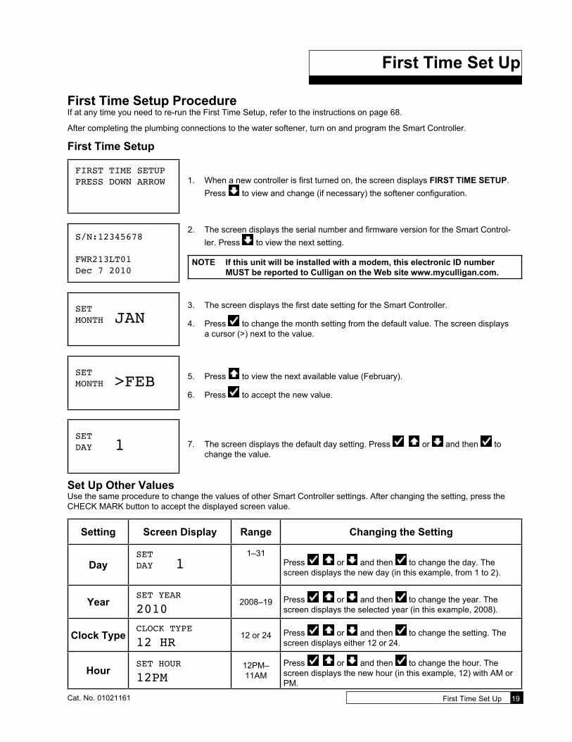
First Time Setup
FIRST TIME SETUPPRESS DOWN ARROW 1. When a new controller is first turned on, the screen displays FIRST TIME SETUP.
Press to view and change (if necessary) the softener configuration.
S/N:12345678
FWR213LT01Dec 7 2010
2. The screen displays the serial number and firmware version for the Smart Control-ler. Press to view the next setting.
NOTE If this unit will be installed with a modem, this electronic ID number MUST be reported to Culligan on the Web site www.myculligan.com.
SETMONTH JAN
3. The screen displays the first date setting for the Smart Controller.
4. Press to change the month setting from the default value. The screen displays a cursor (>) next to the value.
SETMONTH >FEB 5. Press to view the next available value (February).
6. Press to accept the new value.
SETDAY 1 7. The screen displays the default day setting. Press or and then to
change the value.
Set Up Other ValuesUse the same procedure to change the values of other Smart Controller settings. After changing the setting, press the CHECK MARK button to accept the displayed screen value.
Setting Screen Display Range Changing the Setting
DaySETDAY 1
1–31Press or and then to change the day. The screen displays the new day (in this example, from 1 to 2).
YearSET YEAR
20102008–19 Press or and then to change the year. The
screen displays the selected year (in this example, 2008).
Clock TypeCLOCK TYPE
12 HR12 or 24 Press or and then to change the setting. The
screen displays either 12 or 24.
HourSET HOUR
12PM12PM– 11AM
Press or and then to change the hour. The screen displays the new hour (in this example, 12) with AM or PM.
20 Culligan® Smart Controller (GBE) for Softeners and Filters 20 Cat. No. 01021161
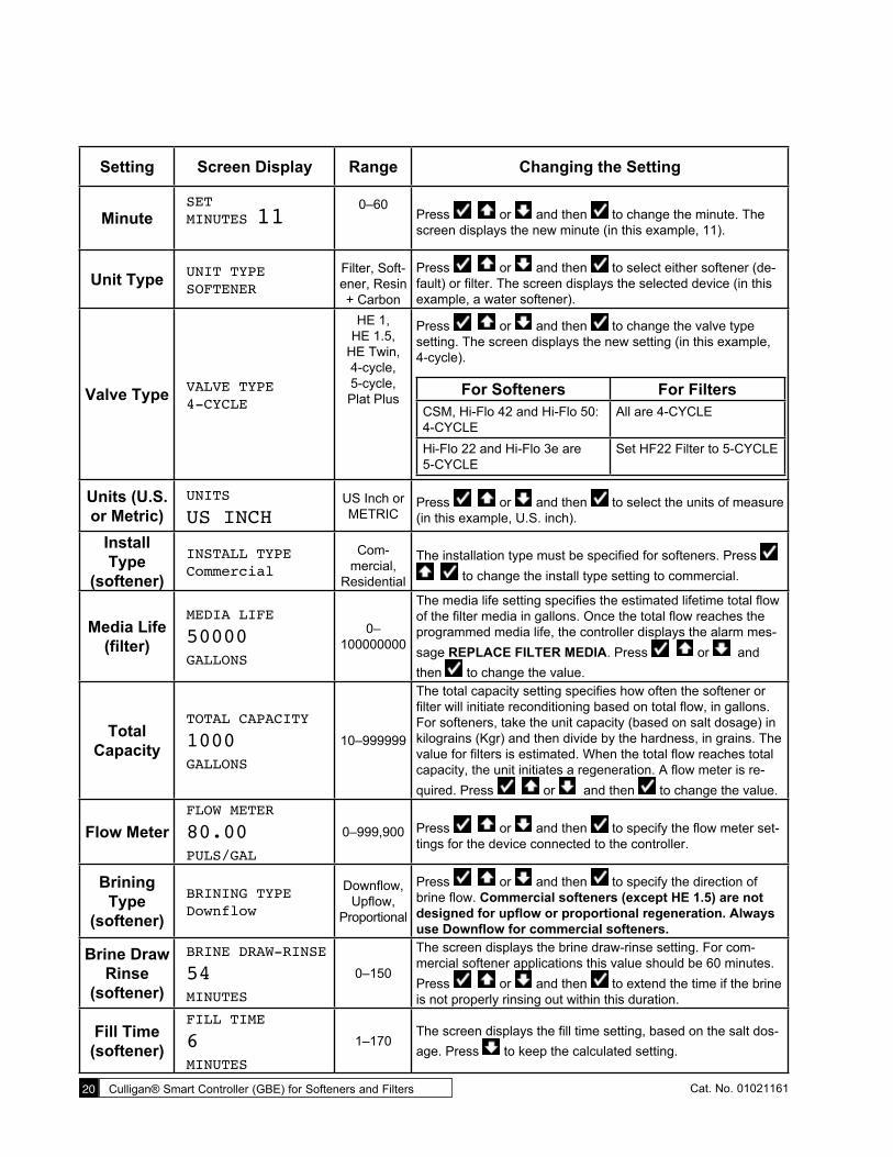
Setting Screen Display Range Changing the Setting
MinuteSETMINUTES 11
0–60Press or and then to change the minute. The screen displays the new minute (in this example, 11).
Unit Type UNIT TYPESOFTENER
Filter, Soft-ener, Resin + Carbon
Press or and then to select either softener (de-fault) or filter. The screen displays the selected device (in this example, a water softener).
Valve Type VALVE TYPE4-CYCLE
HE 1, HE 1.5,
HE Twin, 4-cycle, 5-cycle, Plat Plus
Press or and then to change the valve type setting. The screen displays the new setting (in this example, 4-cycle).
For Softeners For FiltersCSM, Hi-Flo 42 and Hi-Flo 50: 4-CYCLE
All are 4-CYCLE
Hi-Flo 22 and Hi-Flo 3e are 5-CYCLE
Set HF22 Filter to 5-CYCLE
Units (U.S. or Metric)
UNITS
US INCHUS Inch or METRIC
Press or and then to select the units of measure (in this example, U.S. inch).
Install Type
(softener)
INSTALL TYPECommercial
Com-mercial,
Residential
The installation type must be specified for softeners. Press to change the install type setting to commercial.
Media Life (filter)
MEDIA LIFE
50000GALLONS
0– 100000000
The media life setting specifies the estimated lifetime total flow of the filter media in gallons. Once the total flow reaches the programmed media life, the controller displays the alarm mes-sage REPLACE FILTER MEDIA. Press or and then to change the value.
Total Capacity
TOTAL CAPACITY
1000GALLONS
10–999999
The total capacity setting specifies how often the softener or filter will initiate reconditioning based on total flow, in gallons. For softeners, take the unit capacity (based on salt dosage) in kilograins (Kgr) and then divide by the hardness, in grains. The value for filters is estimated. When the total flow reaches total capacity, the unit initiates a regeneration. A flow meter is re-quired. Press or and then to change the value.
Flow MeterFLOW METER
80.00PULS/GAL
0–999,900 Press or and then to specify the flow meter set-tings for the device connected to the controller.
Brining Type
(softener)
BRINING TYPEDownflow
Downflow, Upflow,
Proportional
Press or and then to specify the direction of brine flow. Commercial softeners (except HE 1.5) are not designed for upflow or proportional regeneration. Always use Downflow for commercial softeners.
Brine Draw Rinse
(softener)
BRINE DRAW-RINSE
54MINUTES
0–150
The screen displays the brine draw-rinse setting. For com-mercial softener applications this value should be 60 minutes. Press or and then to extend the time if the brine is not properly rinsing out within this duration.
Fill Time (softener)
FILL TIME
6MINUTES
1–170The screen displays the fill time setting, based on the salt dos-age. Press to keep the calculated setting.

First Time Set Up 21Cat. No. 01021161
Completed First-Time Setup
InitializingJAN-01-10 12:01P
8. When the setup is complete, the circuit board microprocessor automatically calcu-lates softener capacity. The screen displays the initializing status and the current date and time, and then transitions to the home screen.
SOFTENINGJAN-01-10 12:01P
9. The screen displays the current state (alternate display is the next programmed re-generation) and the date/time set for the unit. This is the default home screen.
NOTE For CSM and Hi-Flo 50 softener applications, you must adjust the Aux 2 cycle time for brine refill. Refer to the Brine System charts in the product installation manual for cycle settings.

22 Culligan® Smart Controller (GBE) for Softeners and Filters 22 Cat. No. 01021161
Customizing Set Up
The Smart Controller is designed to simplify the setup and installation process by making some default recommendations during the Initial Setup. The default settings are designed to be appropriate for most common installations.
Default Settings• Downflow Brining2
• Time of Regen = 2:00 AM2
• Regen Time = Delayed2
• Predict Mode OFF3
• 30% Reserve Capacity2
• Time Clock Backup = OFF3
• Day-of-week Regen = OFF3
• Pre-Rinse Mode = OFF1
1These items are changed on the Main Menu / Advanced / System Setup Menu.2These items are changed on the Main Menu / Advanced / Regen Setup Menu.3These items are changed on the Main Menu / Advanced / Regen Trigger Menu.
Depending on the configuration of the system and/or user preferences, you may have to override the default regenera-tion selections. See Advanced Setup Menu, Regeneration Setup Menu or Regeneration Trigger Menu for information on changing default selections.
Advanced SetupSystem SetupDefault values are shown for each selection.
SOFTENINGJAN-01-10 12:01P
1. From the HOME screen, press to view the main menu.
2)MANUAL MODE 3)SET DATE/TIME 4)ACCESSORIES>5)ADV. SETUP
2. The screen displays the main menu. Press to select 5)ADV. SETUP.
>1)SYSTEM SETUP 2)REGEN SETUP 3)CYCLE TIMES 4)REGENTRIGGER
3. The screen displays the advanced setup menu. The menu includes SYSTEM SET-UP, REGEN SETUP, CYCLE TIMES, and REGENTRIGGER.
4. Press to select 1)SYSTEM SETUP.
VALVE TYPE 4-CYCLE 5. The screen displays the valve type setting specified during the first-time setup.
This setting cannot be changed. Press to view the next setting.

Customizing Set Up 23Cat. No. 01021161
Other System Setup ValuesUse the same procedure to change the values of other Smart Controller settings. Press the DOWN ARROW button to scroll through the settings, unless otherwise instructed. After changing the setting, press the CHECK MARK button to ac-cept the displayed screen value. The Smart Controller will display the next system setting from the menu.
NOTE All system setup settings are displayed when setting up a water softener. Settings marked with an asterisk (*) below are also displayed when setting up a filter.
Setting Screen Display Range Changing the Setting
Units (U.S. or Metric)
UNITS
US INCHUS Inch or METRIC
Press or and then to select the units of measure (in this example, U.S. inch).
Multitank System
MULTITANK SYSTEMSINGLE
Single, Progress
Flow, Alternating, Unbal Prog
FLow
Multitank systems include two or more tanks in the system (up to six). They can each be the same size, or one tank can be smaller (Unbal Prog Flow). Please refer to page 42 for multi-tank system setup. Press or and then to specify the tank configuration.
Tank IDPROGRESS FLOWMASTER
Master, Slave1–5
For softeners and filters. This is a multi-tank system setting. Press or and then to identify the unit. Refer to page <?> for info.
Prog Flow Trip
PROG FLOW TRIP
10GPM
0–999
For softeners and filters. When a multi-tank (PROGRESS FLOW) system is selected, press or and then to specify this value. Refer to “Setting up a Multi-Tank System” on page <?>. Set this value on the Master Control only.
Small Tank Trip
SMALL TANK TRIP
5GPM
0–999When Unbal Prog Flow is selected, the smaller tank will have a lower trip point. Set this value to the trip point of the smaller tank.
Prerinse Mode
PRERINSEMODE OFF Off, On
The screen displays the prerinse mode setting, which specifies the unit drain intervals and durations. Press or and then to change the value from OFF to ON.
Rinse if No Flow
RINSE IF NO FLOW
FOR 24HOURS
1–240The screen displays the rinse interval. If prerinse mode is ON, the unit will drain if no flow is detected for the duration of this interval. Press or and then to change the value.
Rinse ForRINSE FOR
5MINUTES
1–60
The screen displays the rinse duration. If prerinse mode is ON, specify the number of minutes the unit should rinse to drain when the RINSE IF NO FLOW duration has passed. Press
or and then to change the setting.
2)MANUAL MODE 3)SET DATE/TIME 4)ACCESSORIES>5)ADV. SETUP
6. The customized setup is complete. The screen displays the advanced setup menu. Press to display the home screen.

24 Culligan® Smart Controller (GBE) for Softeners and Filters 24 Cat. No. 01021161
Regeneration Setup
SOFTENINGJAN-01-10 12:01P
1. From the HOME scrren, press to view the main menu.
2)MANUAL MODE 3)SET DATE/TIME 4)ACCESSORIES>5)ADV. SETUP
2. The screen displays the main menu. Press to select 5)ADV. SETUP.
1)SYSTEM SETUP>2)REGEN SETUP 3)CYCLE TIMES 4)REGENTRIGGER
3. The screen displays the advanced setup menu. The menu includes SYSTEM SET-UP, REGEN SETUP, CYCLE TIMES, and REGENTRIGGER.
4. Press to select 2)REGEN SETUP.
Other Regeneration Setup ValuesUse the same procedure to change the values of other regeneration setup settings. Press to scroll through the set-tings, unless otherwise instructed. After changing the setting, press to accept the displayed screen value. The Smart Controller will display the next system setting from the menu.
NOTE All system setup settings are displayed when setting up a water softener. Settings marked with an as-terisk (*) below are also displayed when setting up a filter. Settings marked with two asterisks (**) are displayed only when setting up a filter.
Setting Screen Display Range Changing the Setting
Total Capacity*
TOTAL CAPACITY
1000GALLONS
10–999999
The screen displays the total capacity setting, which specifies how often the softener or filter will initiate reconditioning based on total flow, in gallons. For softeners, take the unit capac-ity (based on salt dosage) in kilograins (Kgr) and divide by the hardness in grains. The value for filters is estimated. When the total flow reaches total capacity, the filter initiates recondition-ing at the preset time. Press or and then to change the value.
Reserve Capacity
RESERVE CAPACITY
30%(300 GAL)
0–99This setting is generally used for a single-delay system. For a multi-tank system, reserve capacity is not necessary and should be set to a much lower number. Values between 0 and 5 percent are typical. If you do not change this value in a multi-tank system, your unit will regenerate when 30 percent of the capacity remains.
Brining Type
BRINING TYPEDownflow
Downflow, Upflow,
Proportional
Press or and then to specify the direction of brine flow. Commercial softeners (except HE 1.5) are not designed for upflow or proportional regeneration. Always use Downflow for commercial softeners.
Time of Regen
TIME OF REGEN
2:00AM12:00AM–11:59PM
Press or and then to specify the time of day that the unit will regenerate when needed.
Regen Mode*
REGEN MODEDELAYED
Delayed or
Immediate
For softeners and filters. For multi-tank systems, this is nor-mally set to IMMEDIATE. If immediate is selected, be sure to change the Reserve Capacity setting.

Customizing Set Up 25Cat. No. 01021161
Setting Screen Display Range Changing the Setting
Power Up Regen
POWER UP REGEN 3 PLUS HOURS
3 Plus Hours
or No
By default if a power loss is for more than three hours, the unit will regenerate when it regains power. Setting this value to No disables this function, preventing a regeneration after a power outage of any length.
Media Life**
MEDIA LIFE
1000GALLONS
100–1,000,000
For filters only. This setting is used to trigger the media end of life message/condition. Requires a flow meter.
Regen Lockout
REGEN LOCKOUT
FOR 0HOURS
0–12
This setting prevents back-to-back regenerations on multi-tank systems, if necessary. When one unit is done regenerating, the next regeneration cannot begin until the set amount of time has passed. Press or then to specify the duration.
2)MANUAL MODE 3)SET DATE/TIME 4)ACCESSORIES>5)ADV. SETUP
5. The regen setup is complete. The screen displays the advanced setup menu. Press to display the home screen.
Cycle Times Setup
SOFTENINGJAN-01-10 12:01P
1. From the HOME screen, press to view the main menu.
2)MANUAL MODE 3)SET DATE/TIME 4)ACCESSORIES>5)ADV. SETUP
2. The screen displays the main menu. Press to select 5)ADV. SETUP.
1)SYSTEM SETUP 2)REGEN SETUP>3)CYCLE TIMES 4)REGENTRIGGER
3. The screen displays the advanced setup menu. The menu includes SYSTEM SET-UP, REGEN SETUP, CYCLE TIMES, and REGENTRIGGER.
4. Press to select 3)CYCLE TIMES.
Cycle Times SettingsUse the same procedure to change the values of other cycle times settings. Press to scroll through the settings, un-less otherwise instructed. After changing the setting, press to accept the displayed screen value. The Smart Controller will display the next system setting from the menu.
Setting Screen Display Range Changing the Setting
Cycle Times
CYCLE TIMESUSE DEFAULTS
Defaults or Custom
When USE DEFAULTS is selected, the program calculates the cycle times based on hardness and resin volume. When CUS-TOM is selected, you can set custom cycle times. For commer-cial applications, Press or and then to select CUSTOM and verify the settings.

26 Culligan® Smart Controller (GBE) for Softeners and Filters 26 Cat. No. 01021161
Setting Screen Display Range Changing the Setting
Backwash Time
BACKWASH TIME
10MINUTES
0–150 Use this setting to adjust the number of minutes for backwash. The default setting is 10 minutes. You generally will not need to change this setting. Press to view the next setting.
Brine Draw-Rinse
BRINE DRAW-RINSE
60MINUTES
0–150
The screen displays the brine draw-rinse setting. For com-mercial softener applications this value should be 60 minutes. Press or and then to extend the time if the brine is not properly rinsing out within this duration.
Fast Rinse-Time
FAST RINSE-TIME
10MINUTES
0–150
This value is displayed as Fast Rinse-Time for five-cycle valves and Fill Time for four-cycle valves. The value is calculat-ed for household units based on input parameters.
For commercial units, press to keep the default setting of 10 minutes.
Fill Time FILL TIME
377SECONDS
0–9000 The screen displays the fill time setting if a 5-cycle valve is selected, based on the salt dosage. Find this value in the unit’s installation manual. For example, if you have a Hi-Flo 22 WS-90 water softener (3 ft³) and you want to set a capacity of 60,000 grains, the chart in Appendix A of the Hi-Flo 22 manual shows a time setting of 12 minutes. For a 4-cycle valve, the refill is controlled by AUX OUTPUT 2; set the refill time there. See page 48.
For filters, Press to keep the default setting, one (1) minute.
NOTE This time is displayed in seconds. For exam-ple, If you entered 12 minutes during FTS, then this will display 720 seconds.
2)MANUAL MODE 3)SET DATE/TIME 4)ACCESSORIES>5)ADV. SETUP
5. The cycle times setup is complete. The screen displays the advanced setup menu. Press to display the home screen.
Regeneration Triggers SetupDefault values are shown for each selection.
SOFTENINGJAN-01-10 12:01P
1. From the HOME scrren, press to view the main menu.
2)MANUAL MODE 3)SET DATE/TIME 4)ACCESSORIES>5)ADV. SETUP
2. The screen displays the main menu. Press to select 5)ADV. SETUP.
1)SYSTEM SETUP 2)REGEN SETUP>3)CYCLE TIMES 4)REGENTRIGGER
3. The screen displays the advanced setup menu. The menu includes SYSTEM SET-UP, REGEN SETUP, CYCLE TIMES, and REGENTRIGGER.
4. Press to select 4)REGENTRIGGER.

Customizing Set Up 27Cat. No. 01021161
Regeneration Triggers SettingsUse the same procedure to change the values of other regeneration trigger settings. Press to scroll through the set-tings, unless otherwise instructed. After changing the setting, press to accept the displayed screen value. The Smart Controller will display the next system setting from the menu.
NOTE All system setup settings are displayed when setting up a water softener. Settings marked with an asterisk (*) below are also displayed when setting up a filter.
Setting Screen Display Range Changing the Setting
Flow Meter*
FLOW METERCAN TRIGGER
Can or Cannot
This setting requires an optional flow meter (except Hi-Flo 22). Use this setting to tell the controller whether the optional flow meter is used to trigger a regeneration. If set to CAN TRIG-GER, the flow meter is used to count the gallons of soft water until the batch value is reached, at which time a regeneration is triggered. You can install water meter and use it just to moni-tor flow rate and total usage, and not use it to trigger the regen-eration. You can have both the water meter and Aqua-Sensor®/differential pressure installed and able to trigger regeneration. Either one can trigger the regeneration and everything is reset when regeneration is complete.
Aqua Sensor
AQUASENSORCAN TRIGGER
Can or Cannot
This setting requires an optional Aqua-Sensor®. Use this set-ting to tell the controller whether the Aqua-Sensor® is used to trigger a regeneration. If set to CAN TRIGGER, the Aqua-Sen-sor® is used to monitor the hardness front across the resin bed. The probe will sense when the front has reched its sensors, at which time a regeneration is triggered. You can have both the water meter and Aqua-Sensor® installed and able to trigger re-generation. Either one can trigger the regeneration and every-thing is reset when regeneration is complete.
Regen Interval*
REGEN INTERVALNUMBER OF DAYS:0
0–99
Use this setting if using time clock regeneration only or if you would like to have a time clock backup for the installed trig-ger device. It is common to set this at three days, although not necessary.
Predict Mode
PREDICT MODEOFF
Off or On The Predict Mode is used in the flow meter mode to determine the optimum regeneration point. Before the regeneration starts, the control will compare the remaining capacity value with the average daily water use. Although the Smart Controller can use Predict Mode with Immediate regeneration, it works better on single delayed systems. When using predict mode, reduce the reserve capacity of the system to about 2 percent.
If the system reaches zero percent remaining capacity and the Smart Controller is set to IMMEDIATE, the system will regener-ate immediately. If the Smart Controller is NOT set to IMMEDI-ATE, then each night at time of regeneration (TOR), if the re-maining capacity is less than the average daily usage, then the Smart Controller initiates regeneration; if the remaming capac-ity is greater than the average daily usage the Smart Controller will NOT initate regeneration.

28 Culligan® Smart Controller (GBE) for Softeners and Filters 28 Cat. No. 01021161
Setting Screen Display Range Changing the Setting
Regenera-tion On*
REGENERATION ONMONDAYOFF
Sunday–Saturday
On or Off
Use this setting to select the days of the week to regenerate. This is most useful when running the system as time clock only. For commercial multi-tank systems, leave all days to OFF.
The program will go through the rest of the days of the week to set regeneration on or off.
This can also be used to create a Time-Clock backup for the water meter or Aqua-Sensor. When set as a backup, the clock will trigger a regeneration at that day and time even if the unit is in Stand-by and/or has been the whole time.
2)MANUAL MODE 3)SET DATE/TIME 4)ACCESSORIES>5)ADV. SETUP
5. The regeneration trigger setup is complete. The screen displays the advanced setup menu. Press to display the home screen.

Softener and Filter Program Log 29Cat. No. 01021161
Softener and Filter Program Log
Use this log to record the program settings for any Smart Controller (GBE) controlled softener or filter. Circle or enter the observed value. Make additional copies to keep on file near the installation and with your local Culligan dealer.
Program Date: ___________ Installer: _____________________________ Site Location: ____________________
Smart Controller ESN: _____ Firmware Version: _____________________ oSoftener oFilter
Regeneration Initiation (check all that apply): oTime Clock oMeter oAqua-Sensor oOtherAccessories
Aqua-Sensor Installed/Not Installed S Only
Debug ON/OFF S Only
Beeper Mode Always On Always Off
12 Hr. Warnings 24 Hr. Warnings
Aux Input Normal/Alarm
Aux2 Output Type Normally On Normally Off Repeat Cycle
Aux2 Valv Pos
Aux2 Out Delay
Aux2 Out Active
Aux2 Out Off Repeat Cycle
Aux3 Output Type Normally On Normally Off Repeat Cycle
Aux3 Valv Pos
Aux3 Out Delay
Aux3 Out Active
Aux3 Out Off Repeat Cycle
SBT Sensor Installed/Not Installed S Only
Tank Diameter S Only
Salt Geometry Pellet/Rock/ Brick/Special
S Only
Remote Display Installed/Not Installed
Channel #
Radio Frequency 915
Modem Installed/Not Installed
Modem Location Main Control/ In Remote
Call Frequency
Time Zone GMT
Dealer ID
Date Phone #
Chlorinator Installed/Not Installed
Power Level
On Time
Meter Installed/Not Installed
Puls/Gal
Low Flow Limit
High Flow Limit
Service Phone #
Ext Filter Installed/Not Installed S Only
Filter Capacity S Only
Reset Capacity Yes/No S Only
First Time SetupMonth
Day
Year
Clock Type 12 Hr/24 Hr
Hour
Minutes
Unit Type Softener/Filter/R+C
Valve Type HE 1, HE 1.5, HE 1 Twin,
4-Cycle, 5-Cycle, Plat Plus
Units US Inch/Metric
Install Type Residential, Commercial
S Only
Brining Type Downflow, Upflow, Proportional
S Only
Tank Diameter S Only
Hardness S Only
Media Life F Only
Total Capacity F Only
Advanced SetupValve Type HE 1, HE 1.5,
HE 1 Twin, 4-Cycle, 5-Cycle,
Plat Plus
Units US Inch/Metric
Multitank System Single Twin
Progress Flow Alternating
Unbal Prog Flow
Prog Flow Trip
Progress Flow Master/Slave (_____)
Small Tank Trip
Prerinse Mode OFF/ON
Rinse If No Flow
Rinse For
Regeneration SetupTotal Capacity
Reserve Capacity S Only
Brining Type S Only
Time of Regen
Regen Mode Delayed/Immediate
Power Up Regen
Regen Lockout S Only
Media Life F Only
Cycle TimesBackwash
Brine Draw-Rinse
Fast Rinse Time
Fill Time
Regeneration TriggersFlow Meter Can/Cannot
Aqua-Sensor Can/Cannot S Only
Regen Interval
Predict Mode OFF/ON S Only
Regen On
On Remote DisplayRemote Display Installed/Not Installed
Channel #
Radio Frequency 915
Warning! If incorrectly installed, operated or maintained, this product can cause severe injury. Those who install, operate, or maintain this product should be trained in its proper use and warned of its dangers before attempting to install, operate or maintain this product.
30 Culligan® Smart Controller (GBE) for Softeners and Filters 30 Cat. No. 01021161
Installing Accessories
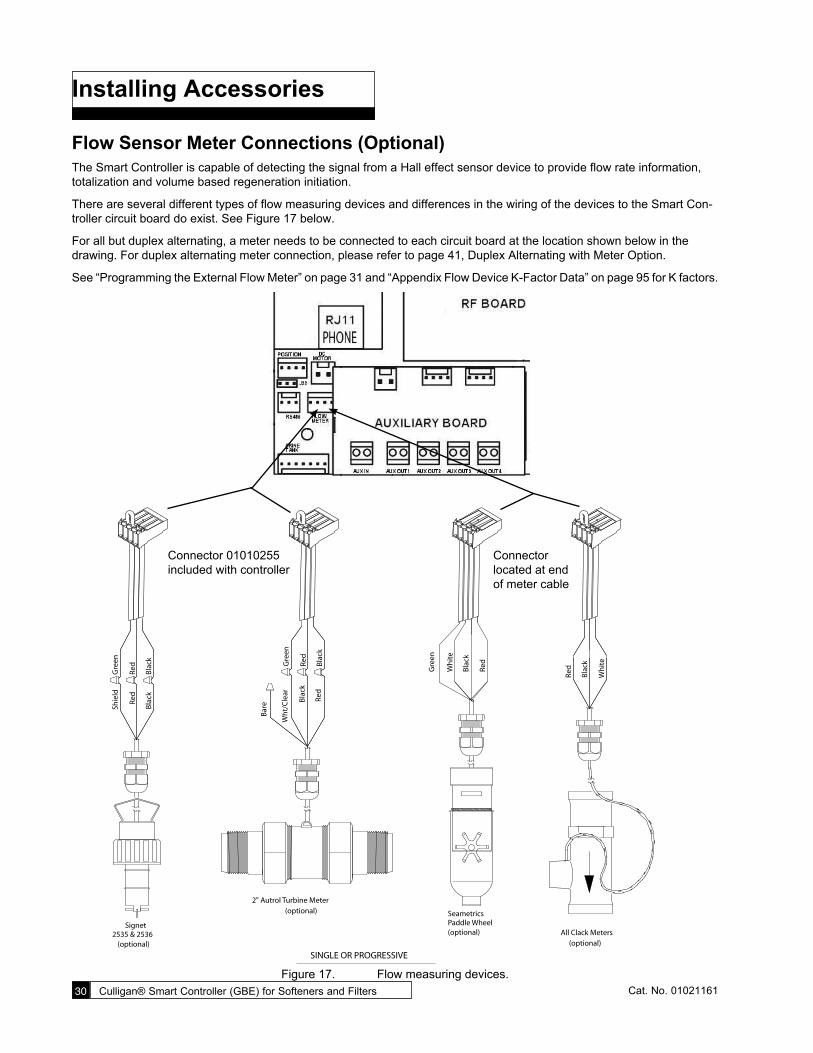
Flow Sensor Meter Connections (Optional)The Smart Controller is capable of detecting the signal from a Hall effect sensor device to provide flow rate information, totalization and volume based regeneration initiation.
There are several different types of flow measuring devices and differences in the wiring of the devices to the Smart Con-troller circuit board do exist. See Figure 17 below.
For all but duplex alternating, a meter needs to be connected to each circuit board at the location shown below in the drawing. For duplex alternating meter connection, please refer to page 41, Duplex Alternating with Meter Option.
See “Programming the External Flow Meter” on page 31 and “Appendix Flow Device K-Factor Data” on page 95 for K factors.
(optional)2535 & 2536
Signet
Bla
ck
Shie
ld
Red
Bla
ck
Gre
en
Red
Paddle Wheel(optional)
Seametrics
Gre
en
Red
Bla
ck
Wh
ite
SINGLE OR PROGRESSIVE
Bar
e
Red
Gre
en
Bla
ckR
ed
Bla
ck
Wh
t/C
lear
2" Autrol Turbine Meter(optional)
Bla
ck
Wh
ite
Red
All Clack Meters(optional)
Connector located at end of meter cable
Connector 01010255 included with controller
Figure 17. Flow measuring devices.
Installing Accessories 31Cat. No. 01021161
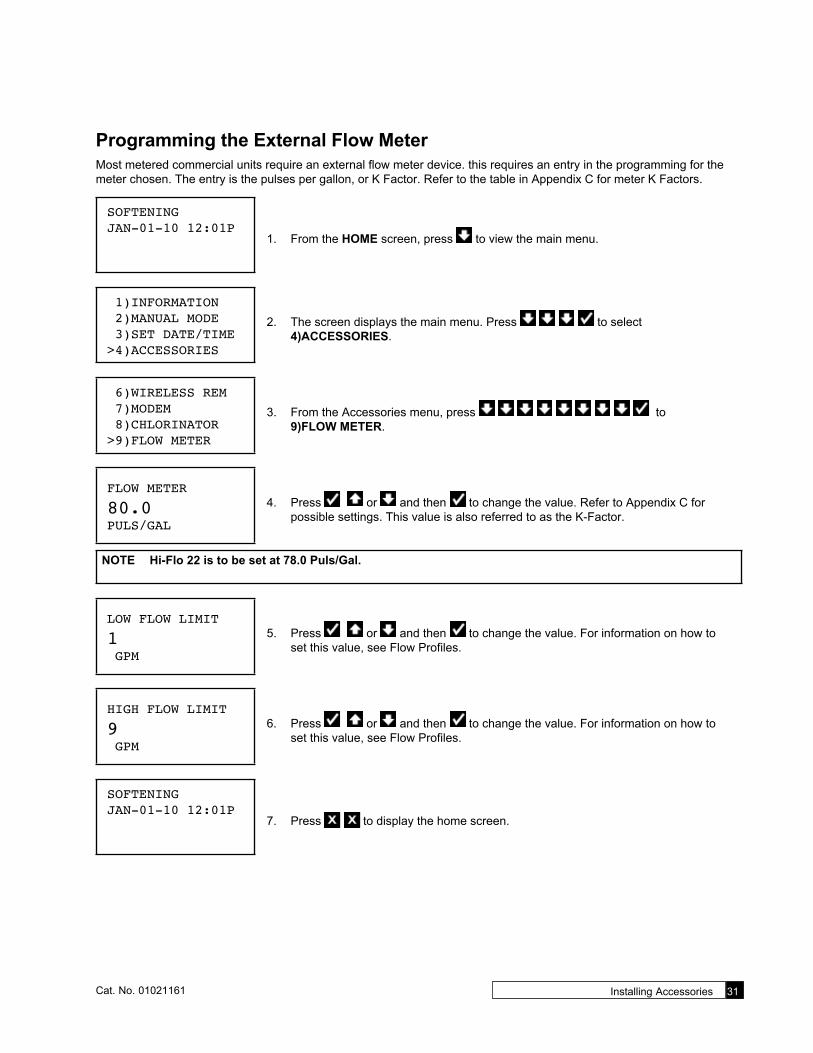
Programming the External Flow MeterMost metered commercial units require an external flow meter device. this requires an entry in the programming for the meter chosen. The entry is the pulses per gallon, or K Factor. Refer to the table in Appendix C for meter K Factors.
SOFTENINGJAN-01-10 12:01P
1. From the HOME screen, press to view the main menu.
1)INFORMATION 2)MANUAL MODE 3)SET DATE/TIME>4)ACCESSORIES
2. The screen displays the main menu. Press to select 4)ACCESSORIES.
6)WIRELESS REM 7)MODEM 8)CHLORINATOR>9)FLOW METER
3. From the Accessories menu, press to 9)FLOW METER.
FLOW METER
80.0PULS/GAL
4. Press or and then to change the value. Refer to Appendix C for possible settings. This value is also referred to as the K-Factor.
NOTE Hi-Flo 22 is to be set at 78.0 Puls/Gal.
LOW FLOW LIMIT
1 GPM
5. Press or and then to change the value. For information on how to set this value, see Flow Profiles.
HIGH FLOW LIMIT
9 GPM
6. Press or and then to change the value. For information on how to set this value, see Flow Profiles.
SOFTENINGJAN-01-10 12:01P
7. Press to display the home screen.

32 Culligan® Smart Controller (GBE) for Softeners and Filters 32 Cat. No. 01021161
Flow ProfilesThis feature allows you to monitor the amount of time that softener or filter spends within different flow ranges. Select flow ranges by setting the Low Flow Limit and High Flow Limit when programming the controller. To best explain this, refer to the following example.
Programming Flow Profiles for a Hi-Flo 22 WS-90The low flow limit can be set to any low value. Consider setting it at the minimum flow rate shown in the manual. This is usually calculated using 2 gpm per square foot of bed area. The WS-90 has a 16” diameter tank, so its cross section is 1.4 square feet (area = PI * r²). 1.4 sf * 2 gpm is 2.8, rounded up to 3. Next you can set the high flow limit at the unit’s rated peak flow, in this case 38 gpm. Here is what the controller is going to do.
First it will take the high flow limit and subtract the low flow limit: 38 – 3 = 35. It then divides this into four equal divisions: 35 ÷ 4 = 8.75, and then tracks six separate values or flow profiles. The flow profile values are displayed in minutes.
• Profile 1 is any flow below the low flow limit.
• Profile 2 is any flow from 3 to 11.75 gpm
• Profile 3 is any flow from 11.76 to 20.51 gpm
• Profile 4 is any flow from 20.52 to 29.26 gpm
• Profile 5 is any flow from 29.27 to 38 gpm (the high flow limit)
• Profile 6 is any flow above the high flow limit.
View flow profiles through the Diagnostics menu. Go to ADVANCED STATS then FLOW STATS and scroll down to FLOW PROFILE R1 through R6. The values displayed are the number of minutes the flow rate has been in that range.
Aqua-Sensor® Schematic (Optional)The Aqua-Sensor® device requires a 2.5 VAC power source. This source is provided via two of the posts on the 24 VAC/2.5 VAC transformer (see figure 19). The two leads from the transformer are run through the same cable grip as the 24 VAC and then must be pushed into the white power connector for connection to the 2.5 V power pins on the GBE circuit board.
The wire connector from the Aqua-Sensor® probe is then routed through the included cable grip and plugged into the Aqua-Sensor terminal on the Smart Controller circuit board. See below.
For information and detailed instructions for installing the Aqua-Sensor in the tank, refer to the specific product manual.
Aqua-Sensor®
If you are going to install an Aqua-Sensor®, you can set up the 2.5 VAC power now.1. Locate the power cord packed with the Aqua-Sensor®. It has two spade terminals on one end of the cable and
two metal “slip in” tabs on the other.
2. Locate the cord grip.
3. The cable can be run through the cable grip and wall from either end of the cable. Make sure the end with the metal tabs goes INSIDE the controller. The spade terminals should be coming out the top end of the grip.
4. Locate the connector at the end of the power cord. You may have already plugged it into the board.
5. Press the two metal tabs on the end of the power cord into the open slots on the connector. They will connect to the pins labeled 2.5 V on the Base Board.The other end of the power cord with the spade terminals should be connected to the two 2.5 VAC terminals on the transformer (see Figure 18).
CAUTION! Verify wiring from terminals to circuit board are correct before applying power to con-trol. 24 VAC power must not be applied to the 2.5 VAC terminals of the circuit board or the circuit board will be damaged.

Installing Accessories 33Cat. No. 01021161
2.5V
METAL TABSConnect to white connector on main power cord
24VACon TRANSFORMER
Power to circuit board 2.5VAC only required
for Aqua-Sensor installations
Power to circuit board 24V
POWER SUPPLYONE transformer is required for each Control
Red
Bla
ck
Blu
e
Wh
ite
Figure 18. 2.5 VAC Aqua-Sensor® power connection (CSM and Hi-Flo 50).
Figure 19. 2.5 VAC Aqua-Sensor® power connection (Hi-Flo 22).

34 Culligan® Smart Controller (GBE) for Softeners and Filters 34 Cat. No. 01021161
Programming the Aqua-Sensor® ProbeAfter installing the Aqua-Sensor® kit 01008779–CSM, Hi-Flo 50, or 01018959–Hi-Flo 22, you must configure the settings.
The Aqua-Sensor® probe should be installed prior to loading the resin in the tank. 1. Run the probe lead through the opening in the top of the tank. Systems with
fiberglass tanks will have a tank plug on the cord. Systems with steel tanks require a 3/4” x 1/2” reducing bushing (included in kit) for the cord grip.
2. Run the probe through the bushing prior to inserting into tank.
3. Use a supplied strain relief to run the connector into the controller.
4. Plug the connector into the circuit board at the position labeled Aqua-Sensor®. See Figure 20.
Configuring the Aqua Sensor® Probe Settings
SOFTENINGJAN-01-10 12:01P
1. From the HOME screen, press to view the main menu.
1)INFORMATION 2)MANUAL MODE 3)SET DATE/TIME>4)ACCESSORIES
2. The screen displays the main menu. Press to select 4)ACCESSORIES.
>1)AQUASENSOR 2)BEEPER 3)AUX IN 4)AUX OUTPUTS
3. The cursor is already pointing at the 1)AQUASENSOR so press to display the Aqua-Sensor® settings.
AQUASENSORNOT INSTALLED 4. Press or and then to change the setting from NOT INSTALLED to
INSTALLED. Press the CHECK MARK button to accept the setting.
AQUASENSOR DEBUGOFF
5. If the Aqua-Sensor setting state is INSTALLED, this screen displays the Aqua-Sensor® debugging mode. Press to toggle between on and off.
6. Press when the correct Aqua-Sensor® debugging mode is displayed.
SOFTENINGJAN-01-10 12:01P
7. Press to display the home screen.
Figure 20.

Installing Accessories 35Cat. No. 01021161
Installing the Smart Brine Tank (SBT Probe) in to the Brine Tank
CAUTION! Do not use the SBT probe if you are using Brine Reclaim.
NOTE For a multi-tank system using one brine tank, connect the probe to the Master controller.
NOTE IMPORTANT! In order for proper probe functioning, you must physically install the probe into the brine tank and fill the brine tank with a minimum of 16” depth of salt prior to selecting INSTALLED on the SBT Sensor settings. Failure to take these steps will result in an error message. If these steps were not followed, go to the SBT settings, select NOT INSTALLED, and then press the X/CANCEL button. When the probe is installed correctly and salt is added to the brine tank, change the SBT setting to INSTALLED.
1. Place the smart brine probe on top of the brine plate as shown in Figure 21.
2. Loop the two zip ties thru the holes in the probe housing and loop the zip ties around the outside of the brine well as shown in Figure 22.
NOTE IMPORTANT! Tighten zip ties securely to prevent movement.3. Use zip tie to snug the top of the brine tank probe against the top of the brine well.
4. Route the smart brine tank probe cable to an appropriate opening in the valve control housing. Use the strain-relief plug provided with the SBT probe for installation.
5. Plug the SBT probe connector into the circuit board at the position labeled Brine Tank. See Figure 23.
Configuring the Smart Brine Tank (SBT) Probe Settings
After the Smart Brine Tank Probe is installed, it is necessary to configure some settings.
SOFTENINGJAN-01-10 12:01P
1. From the HOME screen, press to view the main menu.
1)INFORMATION 2)MANUAL MODE 3)SET DATE/TIME>4)ACCESSORIES
2. The screen displays the main menu. Press to select 4)ACCESSORIES.
Figure 21. Figure 22. Figure 23.
36 Culligan® Smart Controller (GBE) for Softeners and Filters 36 Cat. No. 01021161
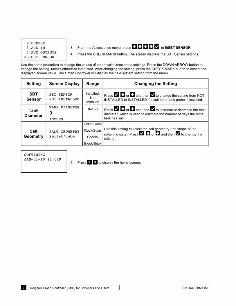
2)BEEPER 3)AUX IN 4)AUX OUTPUTS>5)SBT SENSOR
3. From the Accessories menu, press to 5)SBT SENSOR.
4. Press the CHECK MARK button. The screen displays the SBT Sensor settings.
Use the same procedure to change the values of other cycle times setup settings. Press the DOWN ARROW button to change the setting, unless otherwise instructed. After changing the setting, press the CHECK MARK button to accept the displayed screen value. The Smart Controller will display the next system setting from the menu.
Setting Screen Display Range Changing the Setting
SBT Sensor
SBT SENSORNOT INSTALLED
Installed, Not
Installed
Press or and then to change the setting from NOT INSTALLED to INSTALLED if a salt brine tank probe is installed.
Tank Diameter
TANK DIAMETER
9INCHES
0–150 Press or and then to increase or decrease the tank diameter, which is used to estimate the number of days the brine tank has salt.
Salt Geometry
SALT GEOMETRYPellet/cube
Pellet/Cube
Rock/Solar
Special
Block/Brick
Use this setting to select the salt geometry (the shape of the softening salts). Press or and then to change the setting.
SOFTENINGJAN-01-10 12:01P
5. Press to display the home screen.

Installing Accessories 37Cat. No. 01021161
Brine ReclaimFor brine reclaim, AUX OUT 2 and AUX OUT 3 must be set to open and close the valves to direct the brine. There are four things to set for each aux output. See page 48 for a complete description of auxiliary output settings. Refer to the Brine Reclaim Installation Manual (01018946) for information required to determine appropriate auxiliary settings.
SOFTENINGJAN-01-10 12:01P
1. From the HOME screen, press to view the main menu.
1)INFORMATION 2)MANUAL MODE 3)SET DATE/TIME>4)ACCESSORIES
2. The screen displays the main menu. Press to select 4)ACCESSORIES.
1)AQUASENSOR 2)BEEPER 3)AUX IN>4)AUX OUTPUTS
3. From the Accessories menu, press to select 4)AUX OUTPUTS.
>1)AUX OUT 2 2)AUX OUT 3 4. Press to select 1) AUX OUT 2. The screen displays the settings for the se-
lected auxiliary output.
Setting Screen Display Range Changing the Setting
Aux2 Output Type
AUX2 OUTPUT TYPENormally Off
Normally Off,
Normally On, Repeat
Cycle
5. Press to leave the AUX 2 OUTPUT TYPE setting to NORMALLY OFF. The screen displays the AUX 2 VALV POS setting.
Aux 2 Valve
Position
AUX 2 VALV POSBrine/SRinse
Service, Backwash,
Brine/SRinse
6. Press to change the AUX 2 VALV POS setting to Brine/SRinse. The screen displays the AUX OUT 2 setting.
Aux2 Out Delay
AUX2 OUT DELAY
0Mins
0–25 7. Press to leave the AUX 2 OUT DELAY setting at zero.
Aux2 Out Active
AUX2 OUT ACTIVE
0Secs
0–99998. Press or and then to specify the number of
seconds needed for the selected auxiliary output to be ac-tivated. Refer to the brine reclaim manual, 01018946, for recommended settings.

38 Culligan® Smart Controller (GBE) for Softeners and Filters 38 Cat. No. 01021161
1)AUX OUT 2>2)AUX OUT 3 9. Press the DOWN ARROW button to select 2) AUX OUT 3. Press the CHECK
MARK button. The screen displays the settings for the selected auxiliary output.
Setting Screen Display Range Changing the Setting
Aux3 Output Type
AUX3 OUTPUT TYPENormally Off
Normally Off,
Normally On, Repeat
Cycle
10. Press to leave the AUX 3 OUTPUT TYPE setting at NORMALLY OFF.
Aux 3 Valve
Position
AUX 2 VALV POSBrine/SRinse
Service, Backwash,
Brine/SRinse
11. Press to change the AUX 2 VALV POS setting to Brine/SRinse. The screen displays the AUX OUT 2 setting.
Aux3 Out Delay
AUX3 OUT DELAY
0Mins
0–2512. Press to leave the AUX 3 OUT DELAY setting at zero.
This sets up AUX3 to turn on immediately after AUX2 turns off.
Aux3 Out Active
AUX3 OUT ACTIVE
0Secs
0–9999
13. This is the number of minutes needed for AUX3 to be ac-tivated. Press or and then to change the setting. Refer to the brine reclaim manual, 01018946, for recommended settings.
SOFTENINGJAN-01-10 12:01P
14. Press to save the settings and return to the home screen.
NOTE For testing purposes, use the Aux2 and Aux3 control options available on the Diagnostics and Aux Out Test settings.

Installing Accessories 39Cat. No. 01021161
Multi-Tank SystemsCommunication Cable—Multiple UnitsMultiple units require a communication cable between each unit. Refer to the table below for the cable type, part number and quantity required. Cables are attached to the RS485 terminal of the circuit board.
Table 1. Communication cable requirements
System Configuration Cable Part Number
Qty of Cables Required
Kit Part Number
Qty of blocking solenoids used
Duplex Alternating 01016342 1 01016369 2Duplex Parallel 01016327 1 N/A 0Triplex Parallel 01016327 2 N/A 0Duplex Progressive 01016327 1 01016333 2Triplex Progressive 01016327 2 01016334 3
Multiple units can be set up as progressive flow, alternating or parallel operation. Refer to the instructions and schematics below and on the following pages for connection to the circuit board.
Most multiple tank configurations will also require blocking valves (with the exception of the Hi-Flo 3e softener). These are used to hold tanks offline until needed. Based on the chart above, you can determine how many blocking solenoids are used. These solenoids are included in the alternating and progressive flow kits.
Blocking Solenoid Connection (used on Alternating and Progressive Flow Systems)The solenoid valve wiring attaches to the Aux Out 4 output connection on the auxiliary circuit board. See Figure 24.
SOL
Figure 24. Auxiliary circuit board.

40 Culligan® Smart Controller (GBE) for Softeners and Filters 40 Cat. No. 01021161
Progressive Flow or Parallel FlowIMPORTANT—Setting the Jumpers for Progressive FlowFor progressive flow to operate properly, the first and last units must have the jumpers set to pins 1 and 2 on terminal J22 (see Figure 25 at right). All middle units should have the jumpers on pins 2 and 3 (see Figure 25). The diagram below (Figure 26) shows duplex connections. Repeat the connections on any additional systems.
To Additional Units (if necessary)
Communication Cable 01016327
Jumper Location
Flow Meter Flow MeterUnit 1 Unit 2
Figure 26. Duplex connections.
To RS 485 Comm Porton GBE Circuit Board, #1
CABLE 01016327
To RS 485 Comm Porton GBE Circuit Board, #2
PARALLEL
Additional communication cable connections are used when there are three or more controls. Connect end of second-(01016327) cableto this connector and other end of cable to RS 485 Comm Port on third GBE Circuit Board.
Figure 27. Parallel cable for Smart Controller.
Jumper location for first and last units (end units).
Jumper location for middle units.
1 2 3
Figure 25.
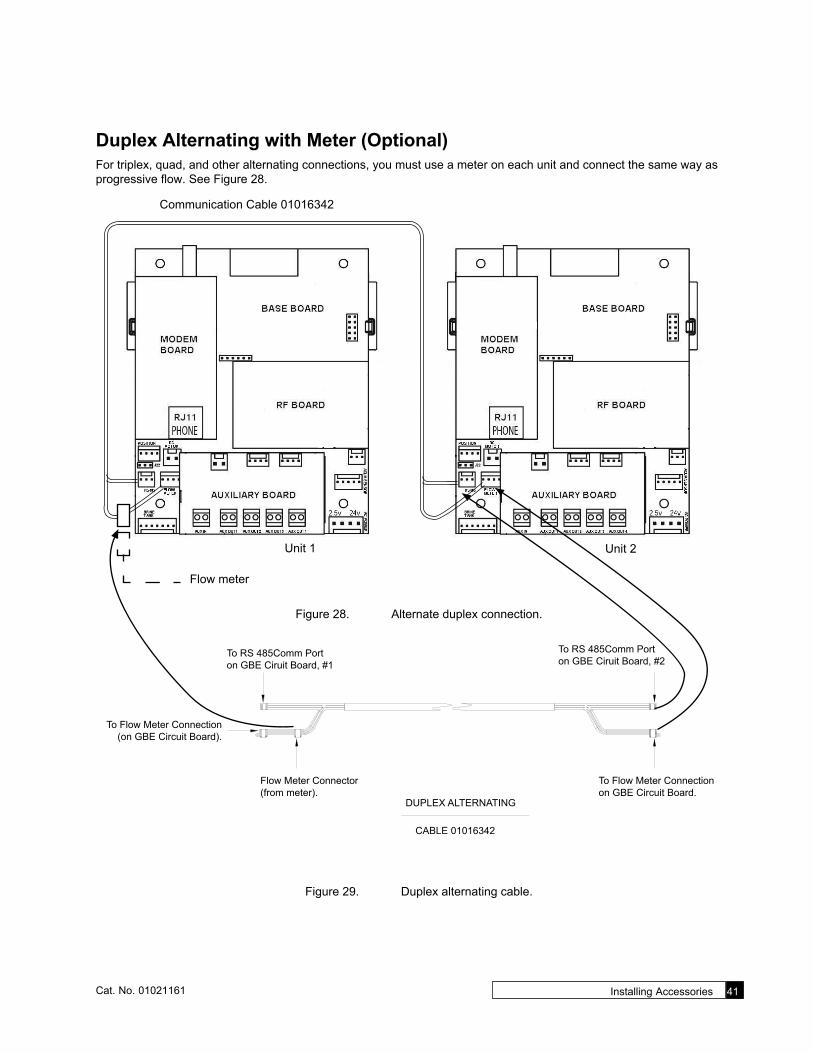
Installing Accessories 41Cat. No. 01021161
Duplex Alternating with Meter (Optional)For triplex, quad, and other alternating connections, you must use a meter on each unit and connect the same way as progressive flow. See Figure 28.
Communication Cable 01016342
Unit 1 Unit 2
Flow meter
Figure 28. Alternate duplex connection.
To RS 485Comm Porton GBE Ciruit Board, #1
To Flow Meter Connectionon GBE Circuit Board.
CABLE 01016342
Flow Meter Connector(from meter).
To Flow Meter Connection(on GBE Circuit Board).
To RS 485Comm Porton GBE Ciruit Board, #2
DUPLEX ALTERNATING
Figure 29. Duplex alternating cable.

42 Culligan® Smart Controller (GBE) for Softeners and Filters 42 Cat. No. 01021161
Setting up a Multi-Tank SystemA Multi-tank system requires additional programming.
SOFTENINGJAN-01-10 12:01P
1. From the HOME scrren, press to view the main menu.
2)MANUAL MODE 3)SET DATE/TIME 4)ACCESSORIES>5)ADV. SETUP
2. The screen displays the main menu. Press to select 5)ADV. SETUP.
>1)SYSTEM SETUP 2)REGEN SETUP 3)CYCLE TIMES 4)REGENTRIGGER
3. The screen displays the advanced setup menu. The menu includes SYSTEM SET-UP, REGEN SETUP, CYCLE TIMES, and REGENTRIGGER.
4. Press to select 1)SYSTEM SETUP.
Multi-Tank System Settings
Setting Screen Display Range Changing the Setting
Units (U.S. or Metric)
UNITS
US INCHUS Inch or METRIC
Press or and then to select the units of measure (in this example, U.S. inch).
Multitank System
MULTITANK SYSTEMSINGLE
Single, Progress
Flow, Alternating, Unbal Prog
FLow
Press or and then to specify the tank configuration.
SINGLE: used only with single tank system.
TWIN: used only with High Efficiency (HE) systems.
PROGRESS FLOW: Used for progressive flow and parallel op-eration. See Prog Flow Trip below.
ALTERNATING: In an alternating system, one tank is always held back, either in regeneration or standby, no matter how many tanks are in the system.
UNBAL PROG FLOW: Used when the tanks in the system are different sizes. See Small Tank Trip below.
Tank IDPROGRESS FLOWMASTER
Master, Slave1–5
In a multi-tank system, one unit must be specified as master. All other units are slaves. For example, in a triplex system, se-lect one unit to be the master and set this setting to MASTER. Set the second unit to SLAVE 1. Set the third unit to SLAVE 2. A multi-tank system may have up to five slaves connected to a master.

Installing Accessories 43Cat. No. 01021161
Setting Screen Display Range Changing the Setting
Prog Flow Trip
PROG FLOW TRIP
10GPM
0–999This setting establishes a flow rate which, when attained, will cause another unit to come online until the total flow rate is less than the established trip point for 30 seconds. Should the flow demand exceed the trip point by a rate equal to or greater than two times the trip point, another unit shall be brought on-line (when Progress Flow or Unbal Prog Flow is selected). Each subsequent equivalent increase in flow demand shall continue to bring additional units on line (up to six total units if the flow demand is six times the TRIP amount). Units shall be returned to a stand-by mode in the reverse order as the system flow decreases by a rate equal to or greater than the trip point. Generally, the trip point is the rated continuous flow rate of one unit. These values can be found in the unit’s instruction manual.
Prog Flow Trip is set only on the master.
NOTE PARALLEL OPERATION: To set up the Smart Controller for parallel operation (all online), set the trip point to zero (0). As long as the flow is above zero, all units will stay online. The trip point is set only on the master unit. You must also set the jumpers as explained on page 40 for progressive flow.
Small Tank Trip
SMALL TANK TRIP
5GPM
0–999
When UNBAL PROG FLOW is selected, you need to set the trip point for the smaller tank. This specifies the flow rate for the smaller tank. This is generally set to the continuous flow rating of the smaller tank. The small tank MUST be set up as the MASTER.
Prerinse Mode
PRERINSEMODE OFF Off, On Press to keep this setting at its current value.
Rinse if No Flow
RINSE IF NO FLOW
FOR 24HOURS
1–240 Press to keep this setting at its current value.
Rinse ForRINSE FOR
5MINUTES
1–60 Press to keep this setting at its current value.
SOFTENINGJAN-01-10 12:01P
5. Press to save the settings and return to the home screen.
Flow meters are required for progressive flow—one for each unit. See “Programming the External Flow Meter” on page 31 to set up the meters.

44 Culligan® Smart Controller (GBE) for Softeners and Filters 44 Cat. No. 01021161
Progressive Flow UpdateWith Firmware version 2.0.9 and later, the Smart Controller can now update all units in the system. After the master is programmed, Follow these instructions:
1. Run the First Time Setup on all remaining units. You can skip through until you get to multi-tank. Select PROGRESS FLOW and set the SLAVE ID. Skip through the rest of FTS.
SOFTENINGJAN-01-10 12:01P
1. From the HOME scrren, press to view the main menu.
1)INFORMATION>2)MANUAL MODE 3)SET DATE/TIME 4)ACCESSORIES
2. The screen displays the main menu. Press to select 2)MANUAL MODE.
MANUAL MODE>PFLOW UPDATE 3. Press to select PFLOW UPDATE. This will transfer the program-
ming to all other systems.
The additional settings needed on the slave units will be for accessories such as Aqua-Sensor and Smart Brine Tank Probe. Service phone number, wireless remote, and modem settings are not transferred because in a multi-tank system they are installed on the Master only.

Installing Accessories 45Cat. No. 01021161
Blocking Solenoid Valve For Multi-tank Alternating Operation NOTE Proceed to page 47 if your system is a single tank configuration. The solenoid valve is only required for
multiple unit alternating or progressive flow systems.
The purpose of the solenoid valve is to assist the controller in providing automatic alternation of multiple tank systems. Each Brunermatic multiport valve in the system will require its own solenoid valve. These solenoids are tubed as follows:
• From solenoid valve port number 1 to Brunermatic multiport valve port number 4.
• From solenoid valve port number 2, tee into the tubing that attaches to the “IN” port on the pilot valve body.
• From solenoid valve port number 3 to port number 2 on the pilot valve body. The detailed tubing schematic is shown below (Figure 30).
2
5DR
3/4
6P
1
Brunermatic
Valve
Figure 30. Alternating/progressive flow parallel system with plugged bypass. Figure 31. Solenoid Valve.

46 Culligan® Smart Controller (GBE) for Softeners and Filters 46 Cat. No. 01021161
Sequence of OperationWhen a softener is in standby or a regeneration cycle, the Smart Controller sends a signal to the P7 Sol-Vlv terminal of the primary circuit board, activating the solenoid valve. The orange LED will be on at this time. When the solenoid valve is electrically activated, ports #1 and #2 of the solenoid (Figure 32) become common. This will direct pressure from a con-stant IN pressure supply to the blocking diaphragm valve, which prohibits the flow of water to service.
Once the Smart Controller signals the unit to return to a Service status, the signal from P7 Sol-Vlv is removed and the solenoid valve is deactivated. When the solenoid valve is electrically deactivated, ports #1 and #3 of the solenoid become common. The orange LED will not be on at this time. This will vent pressure, from the diaphragm valve to drain. The dia-phragm valve opens to allow softened water to flow to service.
3
2 1
To Drain
BlockingDiaphragm
Solenoid Valve EnergizedWhen Tank
in Regen or Standby
N/C N/O
N/O
2
3
1
To Drain
FromPressurized
Source
From BlockingDiaphragm Valve
Solenoid Valve Not EnergizedWhen Tank "Online"
Solenoid Valve
N/C N/O
N/O
Solenoid Valve
FromPressurized
Source
Figure 32.
SOL
Figure 33. Smart Controller board with solenoid connection.
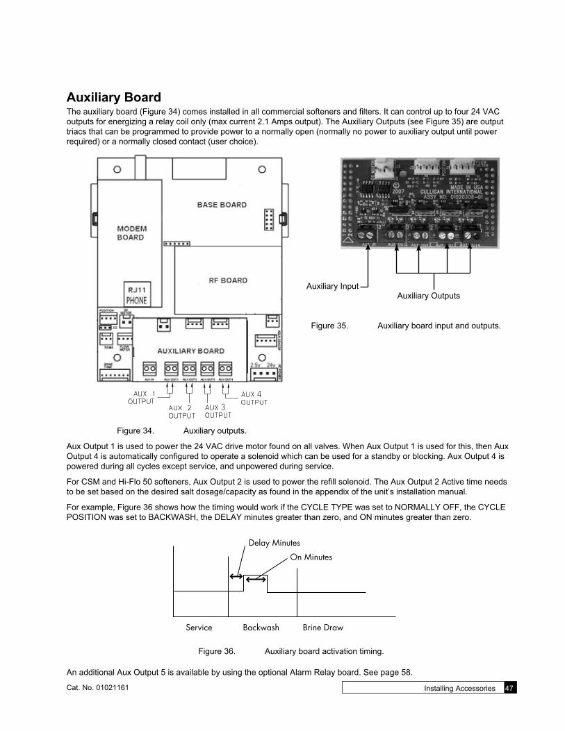
Installing Accessories 47Cat. No. 01021161
Auxiliary BoardThe auxiliary board (Figure 34) comes installed in all commercial softeners and filters. It can control up to four 24 VAC outputs for energizing a relay coil only (max current 2.1 Amps output). The Auxiliary Outputs (see Figure 35) are output triacs that can be programmed to provide power to a normally open (normally no power to auxiliary output until power required) or a normally closed contact (user choice).
3
4
Figure 34. Auxiliary outputs.
Auxiliary Outputs
Auxiliary Input
Figure 35. Auxiliary board input and outputs.
Aux Output 1 is used to power the 24 VAC drive motor found on all valves. When Aux Output 1 is used for this, then Aux Output 4 is automatically configured to operate a solenoid which can be used for a standby or blocking. Aux Output 4 is powered during all cycles except service, and unpowered during service.
For CSM and Hi-Flo 50 softeners, Aux Output 2 is used to power the refill solenoid. The Aux Output 2 Active time needs to be set based on the desired salt dosage/capacity as found in the appendix of the unit’s installation manual.
For example, Figure 36 shows how the timing would work if the CYCLE TYPE was set to NORMALLY OFF, the CYCLE POSITION was set to BACKWASH, the DELAY minutes greater than zero, and ON minutes greater than zero.
Delay Minutes
On Minutes
Service Backwash Brine Draw
Service Backwash Brine Draw
ON SECONDS
@ 1500 gallons, on seconds is activated by GALLONS
@ 3000 gallons, on seconds is activated by GALLONS
@ 4500 gallons, on seconds is activated by OFF MINUTES
OFF MINUTES
EXAMPLEGALLONS: 1500ON SECONDS: 10OFF MINUTES: 15
Figure 36. Auxiliary board activation timing.
An additional Aux Output 5 is available by using the optional Alarm Relay board. See page 58.

48 Culligan® Smart Controller (GBE) for Softeners and Filters 48 Cat. No. 01021161
AUX OUTPUTS SettingsThe output settings for AUX2 and AUX3 are the same.
SOFTENINGJAN-01-10 12:01P
1. From the HOME screen, press to view the main menu.
1)INFORMATION 2)MANUAL MODE 3)SET DATE/TIME>4)ACCESSORIES
2. The screen displays the main menu. Press to select 4)ACCESSORIES.
1)AQUASENSOR 2)BEEPER 3)AUX IN>4)AUX OUTPUTS
3. From the Accessories menu, press to select 4)AUX OUTPUTS.
>1)AUX OUT 2 2)AUX OUT 3 4. Press to select 1) AUX OUT 2. The screen displays the settings for the se-
lected auxiliary output.
Setting Screen Display Range Changing the Setting
Aux2 Output Type
AUX2 OUTPUT TYPERepeat Cycle
Normally Off,
Normally On, Repeat
Cycle
Press to change the AUX 2 OUTPUT TYPE setting. The screen displays the AUX 2 VALV POS setting. Normally On—For this option, select a cycle, a delay time and a duration time. In this mode, the relay is energized through all cycles EXCEPT the cycle you designate. Further, it will delay de-energizing the relay for the duration designated. It will de-energize during that cycle for the amount of time you set after the delay. Normally Off—For this option, select a cycle, a delay time and the duration time. In this mode, the relay is NOT energized through all cycles EXCEPT the cycle you designate. Further, it will delay energizing the relay for the duration designated. It will be energized during the selected cycle for the amount of time you set after the delay. Repeat Cycle—For this option, select a cycle, a delay time, an “on” time, and an “off” time. Once the relay energizes in the selected cycle, it will repeat the “on” time and “off” time settings until the cycle ends.
Aux 2 Valve
Position
AUX 2 VALV POSBrine/SRinse
Service, Backwash,
Brine/SRinse
Press to change the AUX 2 VALV POS setting to Brine/SRinse. The screen displays the AUX OUT 2 setting.
For repeat cycle auxiliary output type, keep the setting at SERVICE.
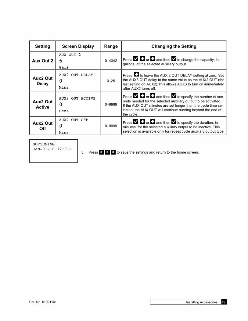
Installing Accessories 49Cat. No. 01021161
Setting Screen Display Range Changing the Setting
Aux Out 2AUX OUT 2
6Gals
0–4342 Press or and then to change the capacity, in gallons, of the selected auxiliary output.
Aux2 Out Delay
AUX2 OUT DELAY
0Mins
0–25Press to leave the AUX 2 OUT DELAY setting at zero. Set the AUX3 OUT delay to the same value as the AUX2 OUT (the last setting on AUX2).This allows AUX3 to turn on immediately after AUX2 turns off.
Aux2 Out Active
AUX2 OUT ACTIVE
0Secs
0–9999
Press or and then to specify the number of sec-onds needed for the selected auxiliary output to be activated. If the AUX OUT minutes are set longer than the cycle time se-lected, the AUX OUT will continue running beyond the end of the cycle.
Aux2 Out Off
AUX2 OUT OFF
0Mins
0–9999Press or and then to specify the duration, in minutes, for the selected auxiliary output to be inactive. This selection is available only for repeat cycle auxiliary output type.
SOFTENINGJAN-01-10 12:01P
5. Press to save the settings and return to the home screen.

50 Culligan® Smart Controller (GBE) for Softeners and Filters 50 Cat. No. 01021161
Auxiliary Output 2 ExampleFor CSM and Hi-Flo 50 softeners, this output is used for the refill solenoid. As an example, let’s say we have a CSM-300-2 and we need to set this up for refill minutes. We are looking for a capacity around 250,000 grains (10 lbs/ft³).
According to the chart on page 92 of the CSM installation manual (01016370), we are looking at a salt dosage of 10.2 lbs/ft³ and need to set the ON minutes of AUX2 to 17.
SOFTENINGJAN-01-10 12:01P
1. From the HOME screen, press to view the main menu.
1)INFORMATION 2)MANUAL MODE 3)SET DATE/TIME>4)ACCESSORIES
2. The screen displays the main menu. Press to select 4)ACCESSORIES.
1)AQUASENSOR 2)BEEPER 3)AUX IN>4)AUX OUTPUTS
3. From the Accessories menu, press to select 4)AUX OUTPUTS.
>1)AUX OUT 2 2)AUX OUT 3 4. Press to select 1) AUX OUT 2. The screen displays the settings for the se-
lected auxiliary output.
AUX2 OUTPUT TYPENormally Off
5. Press to leave the AUX 2 OUTPUT TYPE setting to NORMALLY OFF. The output should energize (turn on) the refill solenoid. The screen displays the AUX 2 VALV POS setting.
AUX 2 VALV POSService 6. Press to leave the setting at SERVICE and view the next setting.
AUX2 OUT DELAY
0Mins
7. This is the activation delay. No delay is necessary; leave this set to zero (0). Press to accept this setting and view the next setting.
AUX2 OUT ACTIVE
0Secs
8. This is the number of minutes needed for AUX2 to be activated. Press to set this to 17 minutes. Press to accept this setting. The screen displays the Auxil-iary Output menu.
SOFTENINGJAN-01-10 12:01P
9. Press to save the settings and return to the home screen.
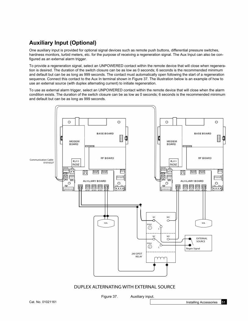
Installing Accessories 51Cat. No. 01021161
Auxiliary Input (Optional)One auxiliary input is provided for optional signal devices such as remote push buttons, differential pressure switches, hardness monitors, turbid meters, etc. for the purpose of receiving a regeneration signal. The Aux Input can also be con-figured as an external alarm trigger.
To provide a regeneration signal, select an UNPOWERED contact within the remote device that will close when regenera-tion is desired. The duration of the switch closure can be as low as 0 seconds; 6 seconds is the recommended minimum and default but can be as long as 999 seconds. The contact must automatically open following the start of a regeneration sequence. Connect this contact to the Aux In terminal shown in Figure 37. The illustration below is an example of how to use an external source (with duplex alternating current) to initiate regeneration.
To use as external alarm trigger, select an UNPOWERED contact within the remote device that will close when the alarm condition exists. The duration of the switch closure can be as low as 0 seconds; 6 seconds is the recommended minimum and default but can be as long as 999 seconds.
NC NO
1
POLE
NC NO
2
POLE
C
C
SOL
Regen Signal
EXTERNALSOURCE
24V DPDTRELAY
DUPLEX ALTERNATING WITH EXTERNAL SOURCE
SOL
Communication Cable 01016327
Figure 37. Auxiliary input.
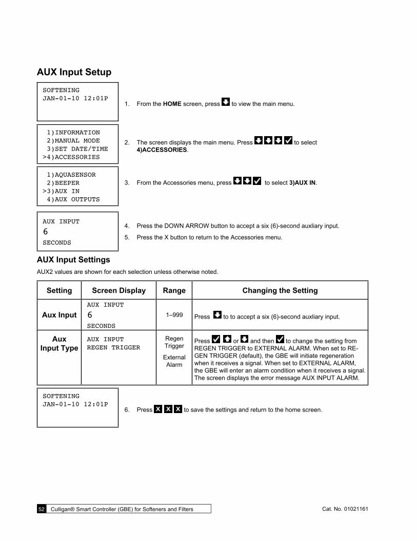
52 Culligan® Smart Controller (GBE) for Softeners and Filters 52 Cat. No. 01021161
AUX Input Setup
SOFTENINGJAN-01-10 12:01P
1. From the HOME screen, press to view the main menu.
1)INFORMATION 2)MANUAL MODE 3)SET DATE/TIME>4)ACCESSORIES
2. The screen displays the main menu. Press to select 4)ACCESSORIES.
1)AQUASENSOR 2)BEEPER>3)AUX IN 4)AUX OUTPUTS
3. From the Accessories menu, press to select 3)AUX IN.
AUX INPUT
6SECONDS
4. Press the DOWN ARROW button to accept a six (6)-second auxliary input.
5. Press the X button to return to the Accessories menu.
AUX Input SettingsAUX2 values are shown for each selection unless otherwise noted.
Setting Screen Display Range Changing the Setting
Aux InputAUX INPUT
6SECONDS
1–999 Press to to accept a six (6)-second auxliary input.
Aux Input Type
AUX INPUTREGEN TRIGGER
Regen Trigger
External Alarm
Press or and then to change the setting from REGEN TRIGGER to EXTERNAL ALARM. When set to RE-GEN TRIGGER (default), the GBE will initiate regeneration when it receives a signal. When set to EXTERNAL ALARM, the GBE will enter an alarm condition when it receives a signal. The screen displays the error message AUX INPUT ALARM.
SOFTENINGJAN-01-10 12:01P
6. Press to save the settings and return to the home screen.
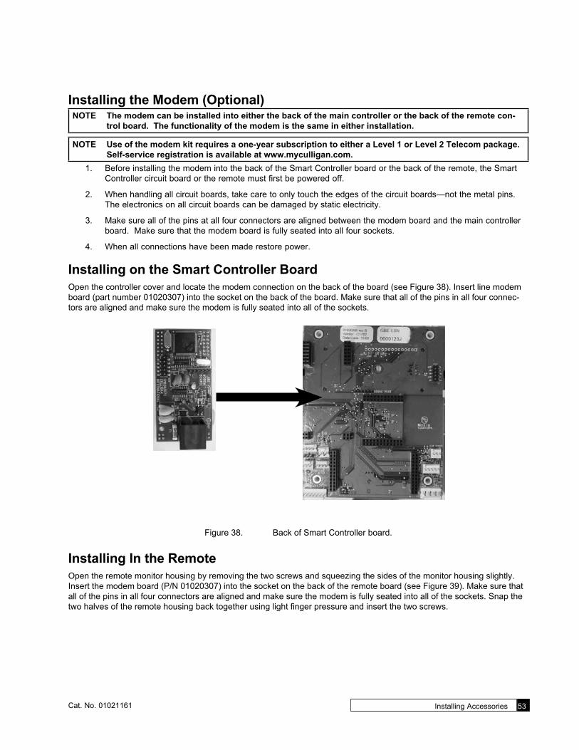
Installing Accessories 53Cat. No. 01021161
Installing the Modem (Optional)NOTE The modem can be installed into either the back of the main controller or the back of the remote con-
trol board. The functionality of the modem is the same in either installation.
NOTE Use of the modem kit requires a one-year subscription to either a Level 1 or Level 2 Telecom package. Self-service registration is available at www.myculligan.com.
1. Before installing the modem into the back of the Smart Controller board or the back of the remote, the Smart Controller circuit board or the remote must first be powered off.
2. When handling all circuit boards, take care to only touch the edges of the circuit boards—not the metal pins. The electronics on all circuit boards can be damaged by static electricity.
3. Make sure all of the pins at all four connectors are aligned between the modem board and the main controller board. Make sure that the modem board is fully seated into all four sockets.
4. When all connections have been made restore power.
Installing on the Smart Controller BoardOpen the controller cover and locate the modem connection on the back of the board (see Figure 38). Insert line modem board (part number 01020307) into the socket on the back of the board. Make sure that all of the pins in all four connec-tors are aligned and make sure the modem is fully seated into all of the sockets.
Figure 38. Back of Smart Controller board.
Installing In the RemoteOpen the remote monitor housing by removing the two screws and squeezing the sides of the monitor housing slightly. Insert the modem board (P/N 01020307) into the socket on the back of the remote board (see Figure 39). Make sure that all of the pins in all four connectors are aligned and make sure the modem is fully seated into all of the sockets. Snap the two halves of the remote housing back together using light finger pressure and insert the two screws.

54 Culligan® Smart Controller (GBE) for Softeners and Filters 54 Cat. No. 01021161
Modem Board
Figure 39. Back of remote board.
GBE Modem Setup
SOFTENINGJAN-01-10 12:01P
1. From the HOME screen, press to view the main menu.
1)INFORMATION 2)MANUAL MODE 3)SET DATE/TIME>4)ACCESSORIES
2. The screen displays the main menu. Press to select 4)ACCESSORIES.
4)AUX OUTPUTS 5)SBT SENSOR 6)WIRELESS REM>7)MODEM
3. From the Accessories menu, press to select 7)MODEM.
GBE Modem Settings
Setting Screen Display Range Changing the Setting
Telephone Modem
TELEPHONE MODEMINSTALLED
Installed, Not
Installed
Press or and then to select INSTALLED if a telephone modem is installed inside the Smart Controller.
Modem Location
MODEM LOCATION IN MAIN CONTROL
In Main Control or In Remote
Press or and then to change the Modem Loca-tion setting. Change this setting only if a modem is installed.

Installing Accessories 55Cat. No. 01021161
Setting Screen Display Range Changing the Setting
Call Frequency
CALL FREQUENCY EVERY 10 REGENS
0–25 Press or and then to specify Call frequency.
The default value of Every 10 regens can be changed from 1 to 25 successful regenerations. If set to 1, the unit will call in the following morning after each regeneration. The interval can also be set to 0, meaning the unit would NEVER call in unless there was a problem detected. It is recommended for a typical installation the default value of EVERY 10 REGENS is used.
Time Zone GMT
TIME zONE GMT
+00:000 to +12 or
-12Press or and then to specify the time zone of the Smart Controller location with respect to Greenwich Mean Time (GMT).
When using a modem, the controller will occasionally access the internet to synchronize the date and time. In order to do this correctly, the control must be told which time zone it is in-stalled in. The time zone is specified as so many hours ahead or behind GMT time. The GMT offset for some common cities is listed below:
GMT OffsetNew York -5:00 (and anywhere in EST)Chicago -6:00 (CST)Denver -7:00 (MST)Los Angeles -8:00 (PST)London 0:00Paris 0:00Rome +1:00
Dealer ID DEALER ID
000000008 digits Press to change the Dealer ID setting. Press or
and then to increase or decrease each digit of the Dealer ID and select the next digit. Press when the correct Dealer ID is displayed. The Dealer ID is your dealership’s account number.
Data Phone #
DATA PHONE #>18884137028
15 digits Press to change the Data Phone Number setting. Press or and then to increase or decrease each digit of
the Data phone number and move to the next digit. Press when the correct Data phone # is displayed. It is necessary to provide a telephone number to be called by the unit. Typically, it is desired that the unit call a local access number. These lo-cal access numbers, for nearly every area code around the globe, can be found from the My Culligan website at http://www.myculligan.com/technical/tech_ref-gbe-boards.asp. The unit can also be programmed with the default toll-free access number. Use a local number whenever possible.
SOFTENINGJAN-01-10 12:01P
4. Press to save the settings and return to the home screen.

56 Culligan® Smart Controller (GBE) for Softeners and Filters 56 Cat. No. 01021161
Test ModemThis menu attempts to send a test message. The screen indicates whether or not this process is successful. Sending a test message will also update the time and date on the Smart Controller to the correct time. If the modem is installed on the main controller (as opposed to installed in the remote control) then this testing process will also check to see if there is an updated version of firmware available on the Culligan servers.
After conducting a phone line test, it is important to verify that the new time and date settings on the controller are correct. If the new time setting has the incorrect value for the hours it is likely that the time zone setting on the control is incorrect. The time zone setting found under the Main Menu / Accessories / Modem screen is displayed in the format of GMT +/- X hours. See “Installing the Modem” on page 50.
SOFTENINGJAN-01-10 12:01P
1. From the HOME screen, press to view the main menu.
3)SET DATE/TIME 4)ACCESSORIES 5)ADV. SETUP>6)DIAGNOSTICS
2. The screen displays the main menu. Press to select 6)DIAGNOSTICS.
6) AUX OUT STAT 7) AUX OUT TEST 8) USE DATA PORT>9) TEST PHONELIN
3. The screen displays the main menu. Press to se-lect 9)TEST PHONELIN. The screen displays the modem phone line test screen.
MODEM TESTEmailing now Please Wait ...
4. Press the CHECK MARK button to begin testing the modem telephone line. The screen displays the status of the test before displaying the results. Do not press any buttons before the test is complete or the controller will return to the Diagnos-tics menu.
Possible Results
MODEM TEST ERRORNO TONE!!
MODEM TEST NOT POSSIBLE NOW TRY LATER!
MODEM EMAIL SUCCESS
MODEM TEST TIMESET SUCCESS
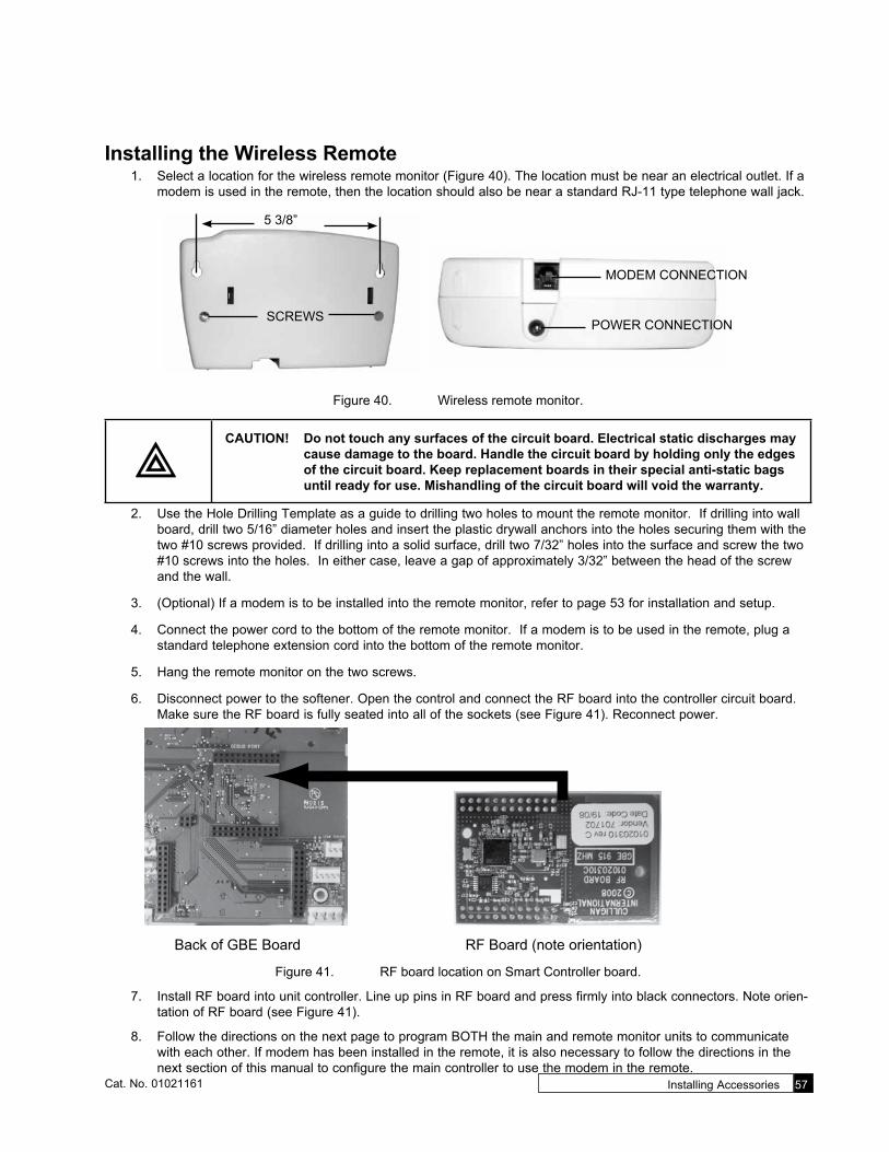
Installing Accessories 57Cat. No. 01021161
Installing the Wireless Remote1. Select a location for the wireless remote monitor (Figure 40). The location must be near an electrical outlet. If a
modem is used in the remote, then the location should also be near a standard RJ-11 type telephone wall jack.
MODEM CONNECTION
POWER CONNECTIONSCREWS
5 3/8”
Figure 40. Wireless remote monitor.
CAUTION! Do not touch any surfaces of the circuit board. Electrical static discharges may cause damage to the board. Handle the circuit board by holding only the edges of the circuit board. Keep replacement boards in their special anti-static bags until ready for use. Mishandling of the circuit board will void the warranty.
2. Use the Hole Drilling Template as a guide to drilling two holes to mount the remote monitor. If drilling into wall board, drill two 5/16” diameter holes and insert the plastic drywall anchors into the holes securing them with the two #10 screws provided. If drilling into a solid surface, drill two 7/32” holes into the surface and screw the two #10 screws into the holes. In either case, leave a gap of approximately 3/32” between the head of the screw and the wall.
3. (Optional) If a modem is to be installed into the remote monitor, refer to page 53 for installation and setup.
4. Connect the power cord to the bottom of the remote monitor. If a modem is to be used in the remote, plug a standard telephone extension cord into the bottom of the remote monitor.
5. Hang the remote monitor on the two screws.
6. Disconnect power to the softener. Open the control and connect the RF board into the controller circuit board. Make sure the RF board is fully seated into all of the sockets (see Figure 41). Reconnect power.
Back of GBE Board RF Board (note orientation)
Figure 41. RF board location on Smart Controller board.
7. Install RF board into unit controller. Line up pins in RF board and press firmly into black connectors. Note orien-tation of RF board (see Figure 41).
8. Follow the directions on the next page to program BOTH the main and remote monitor units to communicate with each other. If modem has been installed in the remote, it is also necessary to follow the directions in the next section of this manual to configure the main controller to use the modem in the remote.

58 Culligan® Smart Controller (GBE) for Softeners and Filters 58 Cat. No. 01021161
Control Valve SetupThe control valve setup prompts the Smart Controller to communicate with a wireless remote.
SOFTENINGJAN-01-10 12:01P
1. From the HOME screen, press to view the main menu.
1)INFORMATION 2)MANUAL MODE 3)SET DATE/TIME>4)ACCESSORIES
2. The screen displays the main menu. Press to select 4)ACCESSORIES.
4)AUX OUTPUTS 5)SBT SENSOR>6)WIRELESS REM 7)MODEM
3. From the Accessories menu, press to select 6)WIRELESS REM. The screen displays the wireless remote settings. Use these to set up the communication between the control valve and the wireless remote.
Control Valve Settings
Setting Screen Display Range Changing the Setting
Remote Display
REMOTE DISPLAY INSTALLED
Installed, Not
Installed
Press or and then to select INSTALLED if the Smart Controller can communicate with a remote display.
Channel # CHANNEL #
>11–254 Press or and then to select the channel num-
ber of the control valve. The CHANNEL # for the control valve must be the same as the CHANNEL # for the Remote Display.
RF Frequency
RF FREQUENCY 915 Mhz
433, 869, or 915
Use this setting to select the correct radio frequency. Do not change the RF frequency for North America installations.
SOFTENINGJAN-01-10 12:01P
4. Press to save the settings and return to the home screen.

Installing Accessories 59Cat. No. 01021161
Wireless Remote SetupThis setup is completed using the wireless remote device.
SOFTENINGJAN-01-10 12:01P
1. From the HOME screen, press to view the main menu.
1)INFORMATION 2)MANUAL MODE 3)SET DATE/TIME>4)ACCESSORIES
2. The screen displays the main menu. Press to select 4)ACCESSORIES.
3)AUX IN 4)AUX OUTPUTS 5)SBT SENSOR>6)WIRELESS REM
3. From the Accessories menu, press to select 6)WIRELESS REM. The screen displays the wireless remote settings. Use these to set up the communication between the control valve and the wireless remote.
Wireless Remote Settings
Setting Screen Display Range Changing the Setting
Remote Display
REMOTE DISPLAY INSTALLED
Installed, Not
Installed
Press or and then to select INSTALLED if the Smart Controller can communicate with a remote display.
Channel # CHANNEL #
>11–254 Press or and then to select the channel num-
ber of the control valve. The CHANNEL # for the control valve must be the same as the CHANNEL # for the Remote Display.
RF Frequency
RF FREQUENCY 915 Mhz
433, 869, or 915
Use this setting to select the correct radio frequency. Do not change the RF frequency for North America installations.
SOFTENINGJAN-01-10 12:01P
4. Press to save the settings and return to the home screen.

60 Culligan® Smart Controller (GBE) for Softeners and Filters 60 Cat. No. 01021161
Check Signal StrengthCheck the signal strength once the control valve and wireless remote are setup. On the Softener Controller, go to the Main Menu/Advanced setup/Diagnostics/Test Wireless to check signal strength. The signal strength indicator (SSI) will show a value of between 0 and 8. If the SSI is at least 4, then the installation is complete. It the SSI drops below 4, then it may be necessary to select an alternate location for the wireless remote.
SOFTENINGJAN-01-10 12:01P
1. From the HOME screen, press to view the main menu.
3)SET DATE/TIME 4)ACCESSORIES 5)ADV. SETUP>6)DIAGNOSTICS
2. The screen displays the main menu. Press to select 6)DIAGNOSTICS.
1)ADVANCED STAT 2)CHECK SENSORS>3)TEST WIRELESS 4)TEST PROGFLOW
3. The screen displays the main menu. Press to select 3)TEST WIRELESS. The screen displays the wireless test screen.
WIRELESS TEST 0/188RSSI=5
4. Press to test the signal strength. The screen displays the test number and total number of attempts and the received signal strength indicator (RSSI). The system will test the signal strength again and repeat until you press again.
SOFTENINGJAN-01-10 12:01P
5. Press to save the settings and return to the home screen.

Installing Accessories 61Cat. No. 01021161
Chlorinator/Relay Board/Aux5 SetupThe GBE board offers support for the Culligan Chlorinator/Relay board (PN 01021961). See Figure 43.
To use the chlorinator/relay board, install it onto the back of the GBE board. See Figure 42.
PLUG INHERE
ALARMBOARD
BACK OFGBE BOARD
Figure 42. Alarm Relay Board—>Smart Controller. Figure 43. Alarm Relay board.
Install the Chlorinator under the Main Menu /Accessories menu. From the Chlorinator Accessory menu select Chlorinator for standard chlorinator behavior.
SOFTENINGJAN-01-10 12:01P
1. From the HOME screen, press to view the main menu.
1)INFORMATION 2)MANUAL MODE 3)SET DATE/TIME>4)ACCESSORIES
2. The screen displays the main menu. Press to select 4)ACCESSORIES.
5)SBT SENSOR 6)WIRELESS REM 7)MODEM>8)CHLORINATOR
3. From the Accessories menu, press to select 8)CHLORINATOR. The screen displays the Chlorinator settings. Use these to set up the Chlorinator board.

62 Culligan® Smart Controller (GBE) for Softeners and Filters 62 Cat. No. 01021161
Alarm Relay Board/Chlorinator Settings
Setting Screen Display Range Changing the Setting
Chlorina-tor
CHLORINATORCHLORINATOR
ChlorinatorError
StatusNetworkNormally
OnNormally
OffRepeat Cycle
Chlorinator—Used to control a chlorinator. Not used in commercial/in-dustrial applications.
Error Status—This mode of operation occurs when the relay board is plugged into the GBE board chlorinator socket. When Error Status is selected, this relay is in the Normally Open position when the GBE board has power AND there are no errors present (“Problem Found” is not showing on the Home screen). The relay is in the Normally Closed Position when the GBE is either powered OFF or when there is an er-ror present on the GBE board.
Network – currently not used.
Normally On—Sets up relay to be Aux5. For this option, select cycle, delay time and duration. In this mode, the relay is energized through all cycles EXCEPT the cycle you designate. Further, it will delay de-energizing the relay for the duration designated. It will de-energize during that cycle for the amount of time you set after the delay.
Normally Off— Sets up relay to be Aux5. For this option, select cycle, delay time, and duration. In this mode, the relay is NOT energized through all cycles EXCEPT the cycle you designate. Further, it will delay energizing the relay for the duration designated. It will be en-ergized during the selected cycle for the amount of time you set after the delay.
Repeat Cycle— Sets up relay to be Aux5. For this option, select cycle, delay time, “on” time, and “off” time. Once the relay energizes in the selected cycle, it will repeat the “on” time and “off” time settings until the cycle ends.
Chlorina-tor
CHLORINATOR INSTALLED
Installed, Not
InstalledPress or and then to select INSTALLED if a Chlorina-tor board is installed inside the Smart Controller.
Power Level
POWER LEVEL
HIGH
Low Medium
HighPress or and then to change the Chlorinator power level setting. Change this setting only if a Chlorinator is installed.
On TimeON TIME
5 MINUTES
1–20Press or and then to specify the number of minutes the chlorinator will operate during the brine draw phase.
NORMAL OPERATION:Terminals 1 and 2 are connected, leaving the lamp circuit open (lamp off)
ERROR CONDITION:Terminals 1 and 3 are connected, completing the lamp circuit (lamp on)
1-C
OM
2-H
C3-
HD
Figure 44. Example of customer wiring to the GBE Alarm Signal Output

Installing Accessories 63Cat. No. 01021161
Smart Controller Alarm Signal OutputThe Smart Controller Alarm Signal Output is provided thru three screw terminals located on the Plug-in Circuit board. These terminals provide a pair of dry contacts rated at 10 A at 240 VAC. One dry contact is open and one is closed at all times as defined in the table below.
When Smart Controller is…
Contact A (screw terminals 1 & 2) Contact B (screw terminals 1 & 3)
Operating Normally Continuity Open circuitIn “Error Condition”, or when the Smart Control-ler is not powered on
Open circuit Continuity
A simple error alarm can be constructed by routing a customer supplied power source thru the Alarm Signal Output contact terminals 1 & 3 as shown in figure 44. The indicating light will be ON any time that the Smart Controller is either not powered on, or if it is in an “error condition.” Alternatively, the Alarm Signal Output contact terminals can be wired to a customer supplied PLC or SCADA system to provide an indication to the customer of the status of the Smart Controller equipment.
Error Add Sensors MeaningMotor Pos Err No Control valve drive motor or motor position sensors have failedMotor Home Err No Control valve drive motor or motor position sensors have failedGBE is unpowered (or board has failed)
No
Ext Filter Alarm No Smart Controller has a programmable count-down gallonage alarm. This error indicates that the countdown has reached zero. Typically this alarm is used as a reminder to replace filter media in an external canister filter
Aqua Salt Error Aqua-Sensor The most recent regeneration was unsuccessful because the strength of the brine was too low.
Low Salt Level SBT Probe This alarm is a prediction that the solid salt remaining in the brine tank will need to be replenished within the next 14 or fewer days. (The predicted days-salt-remaining an be viewed on the Smart Controller display screen.)
Brine Overfill SBT Probe There is too much water in the brine tank.Brine Blocked SBT Probe The rate of brine draw during the most recent eduction was too slow.
The eduction system is either partially clogged or a vacuum leak has formed in the eduction system.
-or-
There was not enough water in the brine tank at the end of fill (which could also be due to a blocked brine line)
Salt Bridging SBT Probe There appears to be a salt bridge in the brine tankNo RF Remote Signal RF wireless remote The controller has lost RF communication with the Smart Controller
wireless remote.
Table 2. Error Conditions on the Smart Controller which will trigger the Alarm Signal Output.
On a multiple-tank softener system, such as a twin-alternating, or progressive flow network, the Alarm Signal Output Re-lay board must be installed on each Smart Controller that the user wants monitored for errors.
When the Smart Controller senses any of the error conditions listed in the table above, the alarm output signal will be triggered. In order to determine the actual individual error(s) which triggered the alarm output signal to be triggered, you would either need to refer to the Smart Controller display screen itself, or to use the PLC communication process de-scribed in this installation manual.

64 Culligan® Smart Controller (GBE) for Softeners and Filters 64 Cat. No. 01021161
Setting the Beeper Mode
SOFTENINGJAN-01-10 12:01P
1. From the HOME screen, press to view the main menu.
1)INFORMATION 2)MANUAL MODE 3)SET DATE/TIME>4)ACCESSORIES
2. The screen displays the main menu. Press to select 4)ACCESSORIES.
1)AQUASENSOR>2)BEEPER 3)AUX IN 4)AUX OUTPUTS
3. From the Accessories menu, press to select 2)BEEPER. The screen dis-plays the beeper settings.
BEEPER MODE ALWAYS OFF 4. Press or and then to change the beeper mode setting: ALWAYS
OFF, ALWAYS ON, 12 HR WARNINGS, or 24 HR WARNINGS.
Beeper Mode Settings
Beeper Mode Display Beeps When Key is Pressed Alarm BeepsAlways on Always AlwaysAlways off Never Never12 hour warnings Never Between 8 AM–8 PM24 hour warnings Never Always
SOFTENINGJAN-01-10 12:01P
5. Press to save the settings and return to the home screen.

Installing Accessories 65Cat. No. 01021161
Service Phone Number If the Modem is not installed it is possible, in addition to displaying the error message, to display a message that reads “Call Culligan at: XXXXXXXXXX” where the telephone number XXXXXXXXXX can be programmed by the dealership (typically programmed to be the telephone number of the dealership).
SOFTENINGJAN-01-10 12:01P
1. From the HOME screen, press to view the main menu.
1)INFORMATION 2)MANUAL MODE 3)SET DATE/TIME>4)ACCESSORIES
2. The screen displays the main menu. Press to select 4)ACCESSORIES.
7)MODEM 8)CHLORINATOR 9)FLOW METER>10)SERVICE PHON
3. From the Accessories menu, press to select 10)SERVICE PHON.
SERVICE PHONE # >
4. Press to change the Service Phone Number setting. Press or and then to increase or decrease each digit of the service phone number and move to the next digit. Press when the correct 14-digit Service phone # is displayed.
SOFTENINGJAN-01-10 12:01P
5. Press to save the settings and return to the home screen.
External Filter The unit can provide alarm feedback for a sediment or carbon filter installed upstream of the unit. The Auxiliary flow alarm can be used to monitor the flow through this filter.
To use this feature it is necessary to specify either the total lifetime totalized flow of the auxiliary filter in either gallons or liters or the total life in days at Main Menu/Accessories/Ext. Filter. Once set, it will begin to track the total gallons through the system flow meter or days in operation. Once the total flow reaches the specified lifetime totalized flow or the set num-ber of days, the system will display the error message “Change Auxiliary Filter” on the main display as well as the remote display and via the telephone modem if these secondary devices are used.
SOFTENINGJAN-01-10 12:01P
1. From the HOME screen, press to view the main menu.
1)INFORMATION 2)MANUAL MODE 3)SET DATE/TIME>4)ACCESSORIES
2. The screen displays the main menu. Press to select 4)ACCESSORIES.

66 Culligan® Smart Controller (GBE) for Softeners and Filters 66 Cat. No. 01021161
8)CHLORINATOR 9)FLOW METER10)SERVICE PHON>11)EXT. FILTER
3. From the Accessories menu, press to se-lect 11)EXT. FILTER.
External Filter Settings
Setting Screen Display Range Changing the Setting
External Filter Alarm
EXT FILTER ALRMNOT INSTALLED
Installed, Not
InstalledPress or and then to change the setting from INSTALLED to NOT INSTALLED.
Filter Capacity
FILTER CAPACITYTIME BASED
Time Based
Flow Based
This alarm setting may be set based on how many gallons have flowed through the unit (requires meter) or may be set based on time.
Filter Capacity
FILTER CAPACITY100000
GALLONS
0–100000Press or and then to change the filter capacity setting.
Filter Capacity
FILTER CAPACITY365DAYS
1–999Press or and then to increase or decrease filter capacity.
Reset Capacity
RESET CAPACITYNO
Yes or NoThe screen displays a confirmation query. Press or and then to change the setting from NO to YES.
The screen displays the Accessories menu.
Change Auxiliary
Filter
CHANGEAUXILIARY FILTER
Yes or No When the screen displays “Change Auxiliary Filter,” press . The screen displays the main menu.
NOTE Once the auxiliary filter has been replaced, the auxiliary filter alarm must be reset by returning to the same menu: Main Menu / Accessories.
SOFTENINGJAN-01-10 12:01P
4. Press to save the settings and return to the home screen.

Installing Accessories 67Cat. No. 01021161
Set Date/TimeIf the unit loses time for some reason, you can use this setting to reset the correct date and time. Please note that if you have a modem installed and connected to the phone line, the unit will check for the correct time each time it calls in.
SOFTENINGJAN-01-10 12:01P
1. From the HOME screen, press to view the main menu.
1)INFORMATION 2)MANUAL MODE>3)SET DATE/TIME 4)ACCESSORIES
2. The screen displays the main menu. Press to select 3)SET DATE/TIME.
Date/Time Settings
Setting Screen Display Range Changing the Setting
MonthSETMONTH JAN
January –December Press and then to change the month.
DaySETDAY 1
1–31Press or and then to change the day. The screen displays the new day (in this example, from 1 to 2).
YearSET YEAR
20102008–19 Press or and then to change the year. The
screen displays the selected year (in this example, 2008).
Clock TypeCLOCK TYPE
12 HR12 or 24 Press or and then to change the setting. The
screen displays either 12 or 24.
HourSET HOUR
12PM12PM– 11AM
Press or and then to select either 24-hour clock (00:00 to 23:59) or 12-hour clock (AM/PM).. The screen dis-plays the new hour (in this example, 12) with AM or PM.
MinuteSETMINUTES 11
0–60Press or and then to change the minute. The screen displays the new minute (in this example, 11).
Daylight Saving
DAYLIGHT SAVING
YESYes or No Press or and then to select either YES or NO. If
you observe daylight savings time in your area, select YES.
SOFTENINGJAN-01-10 12:01P
3. Press to save the settings and return to the home screen.

68 Culligan® Smart Controller (GBE) for Softeners and Filters 68 Cat. No. 01021161
Menu LockoutIt is possible to lock the keypad of the Smart Controller so that users will only have access to the INFORMATION, MANU-AL MODE, and SET DATE/TIME menu screens.
SOFTENINGLOCKED 0 4:58P The system can be locked from the home screen. Press and simultaneously
and holding them down for 10 seconds until you see the word LOCKED.
SOFTENINGUNLOCKED 0 4:58P Repeating this process will unlock the keypad.
NOTE Menu lockout may only be completed from the home screen.
Menu Default—Rerun First Time SetupBelow is the procedure to default the board to factory settings and begin the first time setup.
1. Power down the control.
2. Power up the control while pressing and for at least ten (10) seconds.
3. Release and . The display should be blank—if not go back to step 1.
4. After a brief 10-20 second delay, the screen lights up for two seconds and then displays FIRST TIME SETUP.
5. Follow the first time setup process.

Service and Maintenance 69Cat. No. 01021161
Service and Maintenance
Control Valve InformationThe following information can be displayed at the control valve or remote display.
SOFTENINGJAN-01-10 12:01P
1. From the HOME screen, press to view the main menu.
>1)INFORMATION 2)MANUAL MODE 3)SET DATE/TIME 4)ACCESSORIES
2. The screen displays the main menu. Press to select 1)INFORMATION.
Control Valve Information SettingsThese settings are read-only. Press or to scroll through the settings. Press to view the previous setting.
NOTE All system setup settings are displayed when setting up a water softener. Settings marked with an as-terisk (*) below are also displayed when setting up a filter. Settings marked with two asterisks (**) are displayed only when setting up a filter.
Setting Screen Display Range Setting Description
Media Life Left**
MEDIA LIFE LEFT
1000GALLONS
0–max. media life
If the Media Life setting is specified during first time setup, this screen displays the remaining media life based on usage in gallons.
Media Life Left**
MEDIA LIFE LEFT
3 DAYS
0–max. media life
If the Media Life setting is specified during first time setup, this screen displays the remaining media life based on usage per day.
Salt Tank Level
SALT TANK LEVELOK
OK Low
If a Smart Brine Tank sensor is installed, the screen displays the status of the salt. If the salt tank level is below a specificed lower limit, the screen displays Low.
Remain Capacity
REMAIN CAPACITY
80%0–99%
The softening capacity remaining, displayed as a percentage of the total capacity.
During manually initiated regeneration, assume zero (0) per-cent remaining capacity.
Remain Capacity*
REMAIN CAPACITY
16692GALLONS
0–no limitThe softening or filtering capacity remaining, measured in gal-lons (liters).
Current Flowrate*
CURRENT FLOWRATE
10.8GPM
0–no limitThe current flow rate, measured in gallons (liters) per minute.
Today’s Usage*
TODAY'S USAGE
107GALLONS
0–no limitToday’s water usage, measured in gallons (liters).

70 Culligan® Smart Controller (GBE) for Softeners and Filters 70 Cat. No. 01021161
Setting Screen Display Range Setting Description
Average Daily*
AVERAGE DAILY
6750GALLONS
0–no limitAverage water usage for this configuration.
Total System
Flowrate*
TOTAL SYSTEM
52.2 GPMFLOWRATE
0.0–no limitShown only on Master unit when Progressive Flow system is selected. This is the flow rate through the total system.
Next Regen On*
NEXT REGEN ON
JAN-07JAN-01
–DEC-31Displays the date of the next regeneration, based on average daily water usage.
Total Water Used*
TOTAL WATER USED
107GALLONS
0.0–no limitDisplays the total water used for this configuration. Whole numbers are displayed above 100 gallons.
External Filter
Capacity Remain-
ing*
EXT FILT CAP REM
98896GALLONS
0–external filter
capacity
Displays the remaining capacity of the external filter. When the remaining capacity reaches zero, the system triggers the External Filter Alarm. This information is displayed only if the External Filter Alarm is installed.
SOFTENINGJAN-01-10 12:01P
3. Press to save the settings and return to the home screen.

Manual Regeneration 71Cat. No. 01021161
Manual Regeneration
Follow either procedure to bypass the softener or to initiate a manual regeneration at the control valve or the remote display.
NOTE In multi-tank systems, the regeneration request is sent to the master control. It will allow the unit to regenerate at the next available time.
NOTE Once regeneration is initiated the status can be changed only after the process is complete or by re-setting the motor control in the Diagnostics menu.
Quick Manual RegenerationSOFTENINGJAN-01-10 12:01P 1. From the HOME screen, press and hold to view the home screen plus a regen-
eration status line.
SOFTENINGJAN-09-08 4:58PREGEN TONITE
2. Press and hold for three (3) seconds. Regeneration will be delayed until a specified later time. The screen displays REGEN TONITE on the home screen for about one second.
3. To cancel a delayed regeneration, press and hold the for three (3) seconds. The screen displays REGEN OFF on the home screen.
4. Continue to hold down for six (6) seconds. The screen displays REGEN NOW and the softener will initiate an immediate regeneration.
REGENERATING >JAN-09-08 4:58P 5. If REGEN NOW or REGEN TONITE is selected, the home screen displays
Regenerating.
Standard Manual RegenerationSOFTENINGJAN-01-10 12:01P
1. From the home screen, press to display the main menu.
1)INFORMATION >2)MANUAL MODE 3)SET DATE/TIME 4)ACCESSORIES
2. From the main menu screen, press to view 2) MANUAL MODE.
3. Press . The screen displays the Manual Mode settings.
Standard Regeneration Manual Mode SettingsSetting Screen Display Range Changing the Setting
Manual Mode
MANUAL MODEREGEN NOW
Regen Off
Regen Now
Regen Tonite
REGEN NOW is the default. Press to select this option to begin regeneration immediately.
REGEN OFF will cancel a pending regeneration by canceling the re-generation trigger.
REGEN TONITE specifies that the softener will regenerate that night at 2:00 a.m. (or at the preset regeneration time). The screen displays two status messages: Softening >> and Regen Tonite >>.
SOFTENINGJAN-01-10 12:01P
4. Press to return to the home screen.
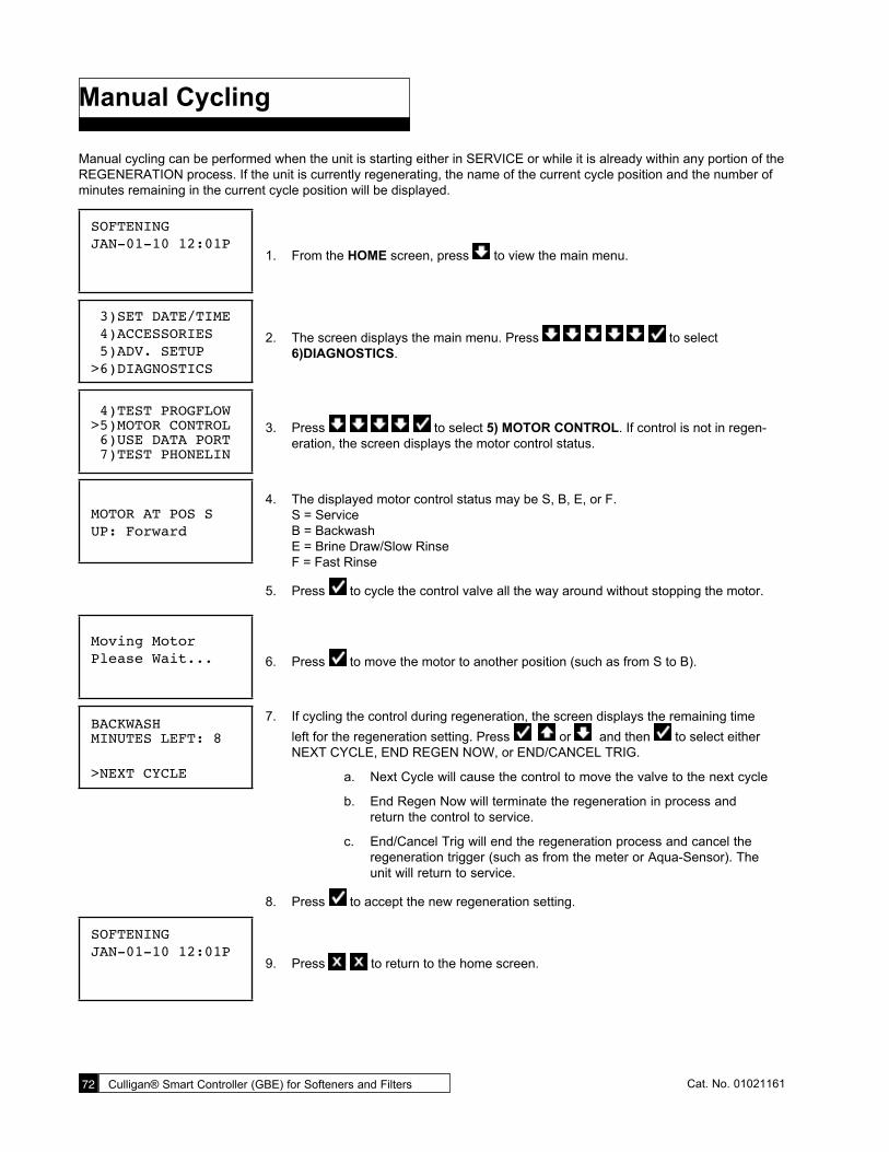
72 Culligan® Smart Controller (GBE) for Softeners and Filters 72 Cat. No. 01021161
Manual Cycling
Manual cycling can be performed when the unit is starting either in SERVICE or while it is already within any portion of the REGENERATION process. If the unit is currently regenerating, the name of the current cycle position and the number of minutes remaining in the current cycle position will be displayed.
SOFTENINGJAN-01-10 12:01P
1. From the HOME screen, press to view the main menu.
3)SET DATE/TIME 4)ACCESSORIES 5)ADV. SETUP>6)DIAGNOSTICS
2. The screen displays the main menu. Press to select 6)DIAGNOSTICS.
4)TEST PROGFLOW >5)MOTOR CONTROL 6)USE DATA PORT 7)TEST PHONELIN
3. Press to select 5) MOTOR CONTROL. If control is not in regen-eration, the screen displays the motor control status.
MOTOR AT POS SUP: Forward
4. The displayed motor control status may be S, B, E, or F. S = Service B = Backwash E = Brine Draw/Slow Rinse F = Fast Rinse
5. Press to cycle the control valve all the way around without stopping the motor.
Moving MotorPlease Wait... 6. Press to move the motor to another position (such as from S to B).
BACKWASH MINUTES LEFT: 8
>NEXT CYCLE
7. If cycling the control during regeneration, the screen displays the remaining time left for the regeneration setting. Press or and then to select either NEXT CYCLE, END REGEN NOW, or END/CANCEL TRIG.
a. Next Cycle will cause the control to move the valve to the next cycle
b. End Regen Now will terminate the regeneration in process and return the control to service.
c. End/Cancel Trig will end the regeneration process and cancel the regeneration trigger (such as from the meter or Aqua-Sensor). The unit will return to service.
8. Press to accept the new regeneration setting.
SOFTENINGJAN-01-10 12:01P
9. Press to return to the home screen.

Error and Alert Codes 73Cat. No. 01021161
Error and Alert Codes
When the Smart Controller identifies that an error has occurred, it is programmed to take steps to attempt to correct the error on its own. If it is unable to correct the problem, the controller will display the message “PROBLEM FOUND.” When an error message is displayed (on either the GBE Controller or the remote display), pressing the CHECK MARK button on the keypad will display the detected error condition(s). Some of these messages will also provide additional information to help correct the error.
The following error messages may display on both the Smart Controller display as well as the Remote Display (if one is connected).
If the main screen displays “PROBLEM FOUND” it indicates that there are one or more errors detected. Push the CHECK MARK button to display the first error present. Press the DOWN ARROW button to show any additional errors present. At the bottom of this list the user can press the CHECK MARK button to clear the error or press the X button to exit. Press-ing the CHECK MARK button on the “CLEAR THE ERROR” message causes the controller to re-check to see if the error condition still exists, if it still exists, the error will remain displayed on the main screen. If the error no longer exists the main menu will display SYSTEM OK.
Error Reason for Error Comment/ Clearing Error MessagePosition Sensor Error
The motor is turning, but the position sensor appears to be incorrect.
Check the motor using manual motor control and the position sensors using Main Menu / Advanced / Diag-nostics Sensors.
Motor Position Error Motor did not move when it should. No feedback from switches.
Use manual motor control to see if motor is actually working and not jammed. Use Diagnostics/ Sensor menu to verify that the optical or mechanical position switches are working.
Brine blocked The flow rate of brine or water to or from the brine tank is fully or partially blocked.
Check brine line for blockages or air leaks. Check eductor and eductor screen for blockages.
Replace Ext Filt Total gallons thru the unit has exceeded the specified capacity of the media.
Replace the media. Reset the media filter life at Main Menu/ Advanced Setup/Regen Settings/ Media Life.
Replace Aux Filter Media
Total gallons thru the secondary filter (i.e. “Big Blue” filter) has exceeded the specified capacity of the big blue.
Replace optional filter cartridge. Reset the aux. Fil-ter media life at Main Menu/ Accessories/ Aux Filter menu.
Call Culligan at xxx-xxx-xxxx
This message is displayed if an error has been detected that requires ser-vicing and no modem installed in the system.
Call the number shown. If possible, place this call using a phone that will allow you to see and enter changes to the main controller if required by the ser-vice technician during the call.
Salt Bridging Brine tank has low concentration of brine.
Use a tool to break up any salt bridge inside the brine tank.
xx days salt remaining
This is a prediction of the number of days until it will be necessary to add salt to the brine tank.
Salt can be added to the brine tank at any time. It is recommended that the brine tank be filled to approxi-mately 2/3 full.
Aqua-Sensor® Salt Error
Aqua-Sensor did not detect brine during the regeneration cycle.
Check brine tank. Add salt if necessary. Check Z ratio of the Aqua-Sensor® at Main Menu/ Advanced / Diag-nostics/ Sensors.
No Remote RF Signal
Main board is not receiving a signal from the remote.
Remote is off, out of range or on a different channel from the main board. If interference is suspected, try moving the remote closer or switching to a different channel on both the main and remote units.
Low Salt level Salt level is low; less than 15 days of salt remaining.
Contact Culligan dealer for salt deviery or fill brine tank with salt.
Low battery Battery needs replacement. Replace with Panasonic Model# CR 2032 3V battery.

74 Culligan® Smart Controller (GBE) for Softeners and Filters 74 Cat. No. 01021161
Error Reason for Error Comment/ Clearing Error MessageBrine overfill Too much water in brine tank.
Plugged drain line flow control (Unit will not draw brine).
Slow leak to brine line.
Faulty eductor piston.
Power outage while control was in refill position.
Check eductor; check for brine draw.
Clean drain line flow control.
Clean eductor screen and nozzle.
Replace eductor piston.
No Refill Failure to refill brine tank. Refill restric-tor plugged.
Air in brine line causes float to slam shut.
Clean or replace refill restrictor. Verify all tubing con-nections are properly assembled.
Motor Home Error Incorrect valve type selected. Change the valve type using the Advanced Setup/Valve Type menu then return to the home screen. The screen will blank while the unit reinitializes.
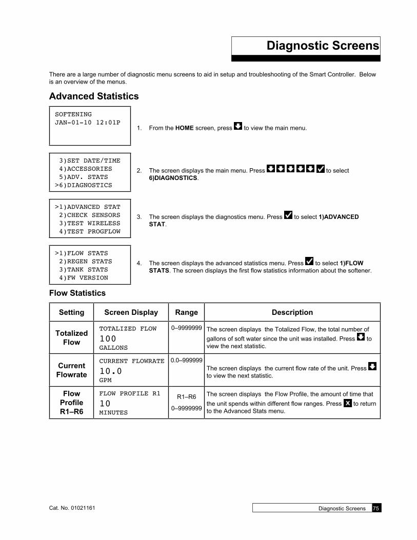
Diagnostic Screens 75Cat. No. 01021161
Diagnostic Screens
There are a large number of diagnostic menu screens to aid in setup and troubleshooting of the Smart Controller. Below is an overview of the menus.
Advanced Statistics
SOFTENINGJAN-01-10 12:01P
1. From the HOME screen, press to view the main menu.
3)SET DATE/TIME 4)ACCESSORIES 5)ADV. STATS>6)DIAGNOSTICS
2. The screen displays the main menu. Press to select 6)DIAGNOSTICS.
>1)ADVANCED STAT 2)CHECK SENSORS 3)TEST WIRELESS 4)TEST PROGFLOW
3. The screen displays the diagnostics menu. Press to select 1)ADVANCED STAT.
>1)FLOW STATS 2)REGEN STATS 3)TANK STATS 4)FW VERSION
4. The screen displays the advanced statistics menu. Press to select 1)FLOW STATS. The screen displays the first flow statistics information about the softener.
Flow Statistics
Setting Screen Display Range Description
Totalized Flow
TOTALIzED FLOW
100GALLONS
0–9999999 The screen displays the Totalized Flow, the total number of gallons of soft water since the unit was installed. Press to view the next statistic.
Current Flowrate
CURRENT FLOWRATE
10.0GPM
0.0–999999The screen displays the current flow rate of the unit. Press to view the next statistic.
Flow Profile R1–R6
FLOW PROFILE R1
10MINUTES
R1–R6
0–9999999
The screen displays the Flow Profile, the amount of time that the unit spends within different flow ranges. Press to return to the Advanced Stats menu.

76 Culligan® Smart Controller (GBE) for Softeners and Filters 76 Cat. No. 01021161
Regeneration Statistics
1)FLOW STATS>2)REGEN STATS 3)TANK STATS 4)FW VERSION
5. The screen displays the advanced statistics. Press to select 2)REGEN STATS. The screen displays the first regeneration statistics information about the softener.
Setting Screen Display Range Description
Total Regens
TOTAL REGENS
150–9999999 The screen displays the total number of regenerations since
the unit was installed. Press to view the next statistic.
Regens in Last 14
Days
REGENS IN LAST 14 DAYS: 0
0–999999The screen displays the number of regenerations in the past 14 days. Press to view the next statistic.
Days Since Last
RegenDAYS SINCE LAST REGEN:1
R1–R6
0–9999999
The screen displays the number of days since the last regen-eration. Press to view the next statistic.
Last Regen On
LAST REGEN ON
JAN-01Jan–Dec,
01–31The screen displays the the date of the last regeneration of the unit (in this example, January 1, 2010). Press to view the next statistic.
Last Regen Trig
LAST REGEN TRIGManual
Manual, Meter, Aqua-
Sensor, (Day), Aux Input, Pow-er Outage
The screen displays the device that triggered the last regen-eration. Press to view the next statistic.
Last BD/SR Time
LAST BD/SR TIME
10MINUTES
0–999999 The screen displays the number of minutes recorded for the last brine draw/slow rinse cycle. When using Aqua-Sensor, this value should be shorter than the programmed value as the Aqua-Sensor will detect when the rinse is complete. Press to view the next statistic.
Last Fill Time
LAST FILL TIME
10SECONDS
0–9999999
The screen displays the number of minutes recorded for the last brine tank refill. You can use this value to check if the proper amount of water is being used to fill the tank. Press to return to the Advanced Stats menu.

Diagnostic Screens 77Cat. No. 01021161
Tank Statistics
1)FLOW STATS 2)REGEN STATS>3)TANK STATS 4)FW VERSION
6. The screen displays the advanced statistics. Press to select 3)TANK STATS. The screen displays the tank statistics information for the softener.
Setting Screen Display Range Description
Remain Capacity
REMAIN CAPACITY
700GALLONS
0–9999999 The screen displays the the remaining capacity of the unit, in gallons. This value can be displayed as a negative number if the unit exceeds the system capacity. The controller will con-tinue to count the number of gallons through the softener when the capacity reaches zero. Press to view the next statistic.
Total Capacity
TOTAL CAPACITY
1000GALLONS
0–9999999The screen displays the total capacity of the unit, in gallons. Press to view the next statistic.
Flow Profile R1–R6
TOTAL WATER USED
50GALLONS
0–9999999The screen displays the total amount of water that has flowed through the unit. Press to return to the Advanced Stats menu.
Firmware VersionFWR213LT01Dec 7 2010 7. From the Advanced Statistics menu, press to select 4) FIRMWARE
VERSION. The screen displays the latest version number and date of the firmware on the unit controller circuit board.
Serial Number
S/N:123456788. From the Advanced Statistics menu, press to select 5) SERIAL
NUMBER. The screen displays the serial number of the circuit board.
Last Power UpLAST POWER UPJAN-01-10 12:01P
9. From the Advanced Statistics menu, press to select 6) LAST POWER UP. The screen displays the date and time when the unit was last powered on. This can be helpful if there was a power outage to see how long the unit has been powered on.
SOFTENINGJAN-01-10 12:01P
10. Press to save the settings and return to the home screen.

78 Culligan® Smart Controller (GBE) for Softeners and Filters 78 Cat. No. 01021161
Check SensorsThe Smart Controller Check Sensors screen displays statistics for the Main Board, Flow Meter, Aqua-Sensor®, and SBT Sensor.
SOFTENINGJAN-01-10 12:01P
1. From the HOME screen, press to view the main menu.
3)SET DATE/TIME 4)ACCESSORIES 5)ADV. STATS>6)DIAGNOSTICS
2. The screen displays the main menu. Press to select 6)DIAGNOSTICS.
1)ADVANCED STAT>2)CHECK SENSORS 3)TEST WIRELESS 4)TEST PROGFLOW
3. The screen displays the diagnostics menu. Press to select 2)CHECK SEN-SORS. The screen displays information about the sensors connected to the main board, flow meter, and Aqua-Sensor®.
Check Sensors Settings
Setting Screen Display Range Description
Main Board
MAIN BOARDPOSITION SENSORHOME:OFF POS:OFF
On or OffThe main board position of Home and Program switches.
Cycle Home Switch
Program Switch
Service Off OffBackwash On On
Brine Draw/Slow Rinse On OffFast Rinse/Refill On On
Flow MeterFLOW METER
10PULS/SEC
N/A This is what the flow meter is recording in pulses per second. This number divided by the K-Factor (pulses per gallon) then multiplied by 60 (60 seconds in a minute) gives you the flow rate in gpm.
Aqua- Sensor Supply Voltage
AQUASENSORSUPPLY VOLTAGE2.5VAC: PASSSIM TEST: FAIL
Pass or Fail
The supply voltage for the Aqua-Sensor®. Refer to page 31 to verify the correct reading.
If the Aqua-Sensor® is not installed, the screen displays NOT INSTALLED instead of the supply voltage.
Aqua- Sensor Stats
AQUASENSORzratio 429496zminimum 0.00000.0% Increase
N/AZRATIO, Impedance ratio: Number calculated by microproces-sor on measured Voltage values that are converted to a digital representation. This is the value that the controller monitors in order to determine need for regeneration and salt rinse-out.
ZMINIMUM, Minimum impedance ratio: reference point that the Z-ratio is compared to, in order to initiate a regeneration. This number is reset after every successful regeneration.
INCREASE: During service, this number represents the per-cent increase of z-ratio over z-minimum. Regeneration is initi-ated when it reaches 7.5% or more for at least six minutes.
This screen is displayed only if the Aqua-Sensor® is installed.

Diagnostic Screens 79Cat. No. 01021161
Setting Screen Display Range Description
SBT Sensor
SBT SENSORSalometer=OPSalt Level=OPFR1=OP FR2=OP
BL
OPExpected Readings on the Sensor/Diagnostic screen when the SBT probe is installed inside the brine tank. See below for settings.
Displays BL (= Blocked) Displays OP (= Open)Salometer Brine at least 1" above the salt plate. Salt Level Normal Operation. Salt level greater than
8" above the salt plate Salt level less than 8" above the salt plate
Flow Rate #1 Water level in brine tank is below salt plate
Water level is brine tank is more than 1" above salt plate
Flow Rate #2 Water level is brine tank is more than 1" above salt plate
Water level in brine tank is below salt plate
Expected Readings from the SBT probe when the probe is not installed in the brine tank.
Normally Probe Inverted Salometer OP BLSalt Level OP OPFlow Rate #1 BL OPFlow Rate #2 OP BL
SBT Average
T3
SBT AVG T3
10SECONDS
The screen displays the Smart Brine Tank T3 measurement. In addition to these four sensors, the SBT probe takes a measurement during each regeneration cycle called T3. This measurement varies from system to system, but is typically between 10 and 60 seconds for a system. When the SBT is turned from UNINSTALLED to INSTALLED on the Accesso-ries menu, the average value of T3 is erased and the system will use the next three regeneration cycles to compute a new T3 average number. During each subsequent regeneration, the new T3 is compared to the average T3 number. If the new T3 exceeds the average T3 by more than 50 percent then the system will display a “Brine Line Blockage—Check Brine Line” error message. The average T3 value is displayed on the diag-nostic screen after the SBT sensor screen.
SBT Last T3
SBT Last T3
10SECONDS
The screen displays the last Smart Brine Tank T3 valve record-ed by the probe.
Test Wireless, Progressive Flow, and Motor Control 1)ADVANCED STAT 2)CHECK SENSORS>3)CHECK WIRELESS 4)TEST PROGFLOW
4. From the diagnostics menu, press to select 3)TEST WIRELESS. The screen displays the wireless test diagnostic.

80 Culligan® Smart Controller (GBE) for Softeners and Filters 80 Cat. No. 01021161
WIRELESS TEST537/541RSSI=5
5. Press to test the signal strength. The screen displays the number of connection attempts and the radio signal strength index. If the screen displays RSSI = 0, there is no wireless signal.
6. Press any button to return to the Diagnostics menu.
Test Progressive Flow 1)ADVANCED STAT 2)CHECK SENSORS 3)CHECK WIRELESS>4)TEST PROGFLOW
1. From the diagnostics menu, press to select 4)TEST PROGFLOW. The screen displays the progressive flow test diagnostic.
PROGRESSIVE TEST1:0000, 2:00003:0000, 4:00005:0000, Tx:1252
2. The progressive test screen will show the data packet transmissions from the mas-ter (Tx) and which slaves are receiving (1, 2, 3, 4, and/or 5). For example, in a tri-plex system, if the transmission from the master (Tx) is 0085, then you should see 1:0085 and 2:0085. 3, 4, and 5 will remain all zeros because no other slaves are connected.
3. Press any key to return to the Diagnostics menu.
Motor Control Diagnostic 2)CHECK SENSORS 3)CHECK WIRELESS 4)TEST PROGFLOW>5)MOTOR CONTROL
1. From the diagnostics menu, press to select 5)MOTOR CON-TROL. The screen displays the motor control diagnostic.
MOTOR AT POS SUP:Forward 2. The screen displays the position of the motor. Press to change the motor posi-
tion and then return to the Diagnostics menu. See “Manual Cycling” on page 72 for more information.
Aux Out Status 3)CHECK WIRELESS 4)TEST PROGFLOW 5)MOTOR CONTROL>6)AUX OUT STAT
1. From the Diagnostics menu, press to select 6)AUX OUT STAT. The screen displays the AUX OUT STATUS settings.
AUX OUT STATUS1:ON 2:OFF3:OFF 4:OFF5:OFF
2. The screen displays the status of each of the controller’s AUX Outputs. Press any key to return to the Diagnostics menu.
Aux Out Test 4)TEST PROGFLOW 5)MOTOR CONTROL 6)AUX OUT STAT>7)AUX OUT TEST
1. From the Diagnostics menu, press to select 7)AUX OUT TEST.

Diagnostic Screens 81Cat. No. 01021161
AUX OUT TESTAUX 3 ON
Press Enter...
2. The AUX OUT TEST allows you to turn the Aux Out switches on or off for testing purposes. For example, the screen displays AUX 1 ON then PRESS ENTER. This indicates that AUX 1 is currently off and if you press enter ( ) the state changes to AUX 1 ON. Press to turn cycle through all available outputs.
AUX OUT TESTCOMPLETE
Press Enter...
3. After the last output, the screen displays COMPLETE. Press to return the out-puts to their previous status; the screen displays the Diagnostics menu.
Use Data Port 5)MOTOR CONTROL 6)AUX OUT STAT 7)AUX OUT TEST>8)USE DATA PORT
1. From the diagnostics menu, press to select 8)USE DATA PORT. The controller will attempt to send a mini-report to the data port.
Mini Report:Sending... 2. The controller is preparing and sending the mini-report.
Mini Report:Sent... 3. The screen indicates when the report has been sent to the data port.
4. Press to return to the diagnostics menu.
Mini Report:Busy! 5. If nothing is attached to the data port, the screen displays a busy message. See
page 89 for data port output information.
Test Phone Line 6)AUX OUT STAT 7)AUX OUT TEST 8)USE DATA PORT>9)TEST PHONELIN
1. From the diagnostics menu, press to select 9)TEST PHONELIN. The screen displays the modem test.
MODEM TESTEmailing nowPlease Wait...
2. The unit sends a test message through the telemetry system and reports a reason code, displayed as “REASON CODE: 1.” See Appendix B, Data Port Output on page 90 for phone line test information.

82 Culligan® Smart Controller (GBE) for Softeners and Filters 82 Cat. No. 01021161
Menu Overview

Menu Overview 83Cat. No. 01021161

84 Culligan® Smart Controller (GBE) for Softeners and Filters 84 Cat. No. 01021161

Menu Overview 85Cat. No. 01021161

86 Culligan® Smart Controller (GBE) for Softeners and Filters 86 Cat. No. 01021161
Smart Controller (GBE) Parts and Accessories
Part Number ItemComplete Controls
01020677 Smart Controller Complete for CSM01020676 Smart Controller Complete for Hi-Flo 42, Hi-Flo 5001021766 Smart Controller Complete for Hi-Flo 3e, 3"01021596 Hi-Flo 22 Softener Control Valve with Smart Controller01021597 Hi-Flo 22 Filter Control Valve with Smart Controller01021123 Hi-Flo 3e Softener Valve with Smart Controller, HWB, 2" (16–24" tank)01021124 Hi-Flo 3e Softener Valve with Smart Controller, HWB, 2” (30” tank)01021125 Hi-Flo 3e Softener Valve with Smart Controller, NHWB, 2” (16–24” tank)01021126 Hi-Flo 3e Softener Valve with Smart Controller, NHWB, 2” (30” tank)01021765 Hi-Flo 3e Softener Valve with Smart Controller HWB, 3”01021764 Hi-Flo 3e Softener Valve with Smart Controller NHWB, 3”
Accessories and Replacement Parts
01020745 Replacement Smart Controller Board01020498 Replacement Key pad01020493 Face Plate, Smart Controller01020748 Auxiliary Board01020747 Modem Board01020750 RF Board01022238 Chlorinator/Alarm Relay Board01020553 Remote Display—Complete for Softener/Filter ONLY01014897 Transformer01020447 Smart Brine Tank Accessory01008779 Aqua-Sensor—Steel Tank01018959 Aqua-Sensor—Fiberglass TankCR 2032 Battery (available at local electronics and retail stores)
Cables and Kits
01016327 Communication Cable01016342 Communication Cable – Duplex Alternating01016333 Duplex Progressive Kit01016334 Triplex Progressive Kit01016369 Duplex Alternating Kit01021402 SBT Extension Cable, 20ft01021507 PLC-USB Communication Cable01021509 PLC-RS485 Communication Cable01021508 PLC-RS232 Communication Cable01023103 PLC-Modbus Communication Cable01023227 Cable, Disc Meter
Conversion Kits01022166 Hi-Flo 22 MVP to Hi-Flo 22 Smart Controller01022162 Hi-Flo 3/2900/MVP to Hi-Flo 3e/Smart Controller01022164 3900 3" to Smart Controller01022165 Universal Conversion, works on Hi-Flo 2/2e, 2850, 315001018209 Fleck 2" Meter Conversion Kit, Mechanical to Electronic, 8 ft. Cable01023062 Fleck 3" Meter Conversion Kit, Mechanical to Electronic

Appendix A Programming Examples 87Cat. No. 01021161
Appendix A Programming Examples
Quick Programming—First Time Setup with Delayed RegenerationHi-Flo 22 Softener (WS-090, 5-Cycle) with Single Meter: salt dosage=30, hardness=15 gpg

88 Culligan® Smart Controller (GBE) for Softeners and Filters 88 Cat. No. 01021161
Quick Programming—Duplex Progressive Flow with Aqua-Sensor®
CSM 450-2: salt dosage=90 lbs, hardness=24 gpgNOTE Perform first-time setup and programming for Unit 2 and then for Unit 1.

Appendix A Programming Examples 89Cat. No. 01021161
Quick Programming Chart—Duplex Alternating FlowCSM 300-2: salt dosage=150 lbs, hardness=18 gpgNOTE Perform first-time setup and programming for Unit 2 and then for Unit 1.

90 Culligan® Smart Controller (GBE) for Softeners and Filters 90 Cat. No. 01021161
Quick Programming Chart—Triplex with Parallel Flow/Brine ReclaimCSM 750-3: salt dosage=375 lbs, hardness=40 gpgNOTE Perform first-time setup and programming for Unit 3, then Unit 2, and then for Unit 1.

Appendix A Programming Examples 91Cat. No. 01021161
Quick Programming Chart—CSM Filter (Single Time Clock Regeneration)NOTE Set up Total Capacity only if the system configuration uses a meter to trigger regeneration.
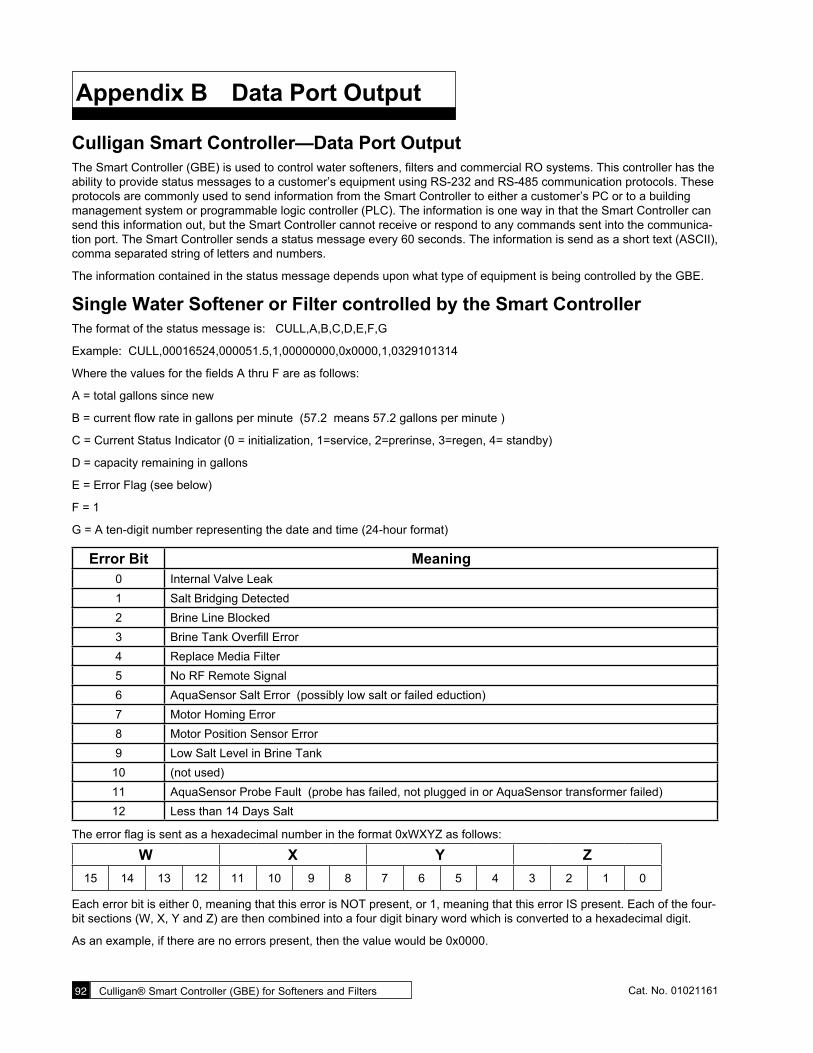
92 Culligan® Smart Controller (GBE) for Softeners and Filters 92 Cat. No. 01021161
Appendix B Data Port Output
Culligan Smart Controller—Data Port Output The Smart Controller (GBE) is used to control water softeners, filters and commercial RO systems. This controller has the ability to provide status messages to a customer’s equipment using RS-232 and RS-485 communication protocols. These protocols are commonly used to send information from the Smart Controller to either a customer’s PC or to a building management system or programmable logic controller (PLC). The information is one way in that the Smart Controller can send this information out, but the Smart Controller cannot receive or respond to any commands sent into the communica-tion port. The Smart Controller sends a status message every 60 seconds. The information is send as a short text (ASCII), comma separated string of letters and numbers.
The information contained in the status message depends upon what type of equipment is being controlled by the GBE.
Single Water Softener or Filter controlled by the Smart ControllerThe format of the status message is: CULL,A,B,C,D,E,F,G
Example: CULL,00016524,000051.5,1,00000000,0x0000,1,0329101314
Where the values for the fields A thru F are as follows:
A = total gallons since new
B = current flow rate in gallons per minute (57.2 means 57.2 gallons per minute )
C = Current Status Indicator (0 = initialization, 1=service, 2=prerinse, 3=regen, 4= standby)
D = capacity remaining in gallons
E = Error Flag (see below)
F = 1
G = A ten-digit number representing the date and time (24-hour format)
Error Bit Meaning0 Internal Valve Leak1 Salt Bridging Detected2 Brine Line Blocked3 Brine Tank Overfill Error4 Replace Media Filter5 No RF Remote Signal6 AquaSensor Salt Error (possibly low salt or failed eduction)7 Motor Homing Error8 Motor Position Sensor Error9 Low Salt Level in Brine Tank10 (not used)11 AquaSensor Probe Fault (probe has failed, not plugged in or AquaSensor transformer failed)12 Less than 14 Days Salt
The error flag is sent as a hexadecimal number in the format 0xWXYZ as follows:
W X Y Z15 14 13 12 11 10 9 8 7 6 5 4 3 2 1 0
Each error bit is either 0, meaning that this error is NOT present, or 1, meaning that this error IS present. Each of the four-bit sections (W, X, Y and Z) are then combined into a four digit binary word which is converted to a hexadecimal digit.
As an example, if there are no errors present, then the value would be 0x0000.

Appendix B Data Port Output 93Cat. No. 01021161
If there were a ‘Replace Media Filter’, ‘Aquasensor Salt Err’ and ‘Motor Position Sensor Error’ present then bits 4, 6 and 8 would be set to 1 and all other bits would be 0, respectively.
W X Y ZError Bits 15 14 13 12 11 10 9 8 7 6 5 4 3 2 1 0
Binary 0 0 0 0 0 0 0 1 0 1 0 1 0 0 0 0
hexadecimal 0 1 5** 0
Error Flag 0x0150
*Note that the first two characters of the error flag are always “0x” to signify that this is a hexadecimal number
** In hexadecimal, the number 4 bit equals 1, the number 5 bit equals 2, the number 6 bit equals 4, and the number 7 bit equals 8. Therefore, when you add the #4 bit value to the #1 bit value, you get 5.
So the value of the error flag would be 0x0150 if these three errors were present.
NOTE If the GBE is controlling a filter (instead of a water softener) then the above message definitions are identical, but that error flags 1,2,3,6,9 and 11 will always be zero for a filter.
Progressive Flow System of Smart Controller-Controlled Water SoftenersThe format of the status message for a progressive flow network consists of a series of individual lines of information, one line for each of the Smart Controller-controlled softeners. For example, in a triplex progressive flow network, every 60 seconds, the data port on the master unit will send out the following three lines of information:
CULL,A1,B1,C1,D1,E1,1,G1
CULL,A2,B2,C2,D2,E2,2,G2
CULL,A3,B3,C3,D3,E3,3,G3
example:
CULL,00052754,000003.7,1,00009110,0x0000,1,0329101314
CULL,00042674,000003.5,1,00004321,0x0000,2,0329101314
CULL,00010204,000000.0,4,00005444,0x0000,3,0329101314
The 1 at the end of the first line indicates that this line is the status for the Master unit in the progressive flow network. The 2 and 3 on the subsequent lines indicate that this data is for slave unit #1 and slave unit #2, respectively. The infor-mation contained on each line is of the same format as described in the Single softener section above.
Electrical ConnectionsThe Culligan Data Cable Connector is terminated with a D-sub9 style female termination. The customer must provide the following pin connections:
Pin Function3 (Input) TD (data coming FROM the GBE board2 (Output) RD (this line is required even though no data is sent TO the GBE board)7 (Input) RTS8 (Output) CTS5 (Signal gnd) GND
The data coming from the Smart Controller board is at the following conditions:
Bits Per Second: 9600 Data Bits: 8 Parity: None Stop Bits: 1 Flow Control: None
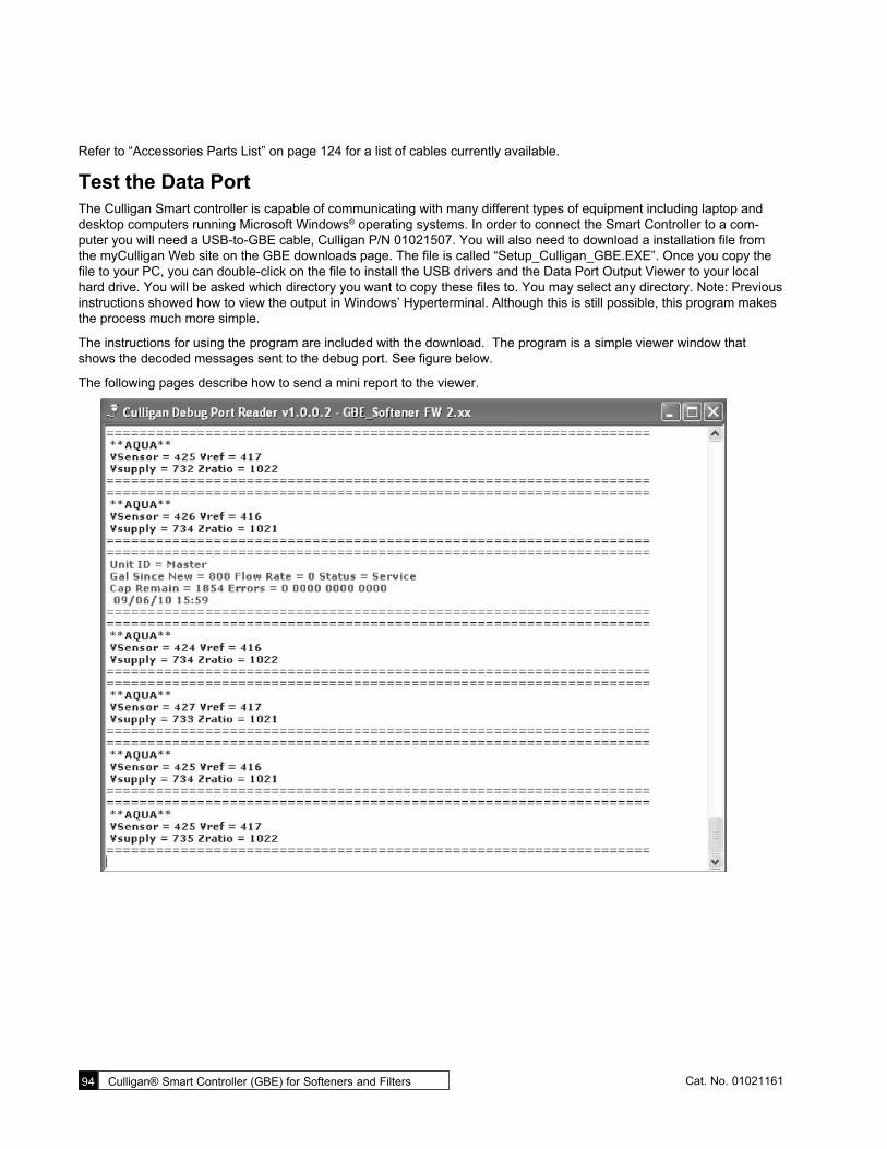
94 Culligan® Smart Controller (GBE) for Softeners and Filters 94 Cat. No. 01021161
Refer to “Accessories Parts List” on page 124 for a list of cables currently available.
Test the Data PortThe Culligan Smart controller is capable of communicating with many different types of equipment including laptop and desktop computers running Microsoft Windows® operating systems. In order to connect the Smart Controller to a com-puter you will need a USB-to-GBE cable, Culligan P/N 01021507. You will also need to download a installation file from the myCulligan Web site on the GBE downloads page. The file is called “Setup_Culligan_GBE.EXE”. Once you copy the file to your PC, you can double-click on the file to install the USB drivers and the Data Port Output Viewer to your local hard drive. You will be asked which directory you want to copy these files to. You may select any directory. Note: Previous instructions showed how to view the output in Windows’ Hyperterminal. Although this is still possible, this program makes the process much more simple.
The instructions for using the program are included with the download. The program is a simple viewer window that shows the decoded messages sent to the debug port. See figure below.
The following pages describe how to send a mini report to the viewer.

Appendix B Data Port Output 95Cat. No. 01021161
Send a Test Message from the Smart Controller
SOFTENINGJAN-01-10 12:01P
1. From the HOME screen, press to view the main menu.
3)SET DATE/TIME 4)ACCESSORIES 5)ADV. STATS>6)DIAGNOSTICS
2. The screen displays the main menu. Press to select 6)DIAGNOSTICS.
5)MOTOR CONTROL 6)AUX OUT STAT 7)AUX OUT TEST>8)USE DATA PORT
1. From the diagnostics menu, press to select 8)USE DATA PORT. The controller will attempt to send a mini-report to the data port.
Mini Report:Sending... 2. The Smart Controller sends a test message to the hyperterminal screen that gen-
erates a Mini Report. See Figure 44.
Mini Report:Sent... 3. The screen indicates when the report has been sent to the data port.
4. Press to return to the diagnostics menu.

96 Culligan® Smart Controller (GBE) for Softeners and Filters 96 Cat. No. 01021161
*** MINI REPORT ***
SN = 00000041
FW Version = FWR210LT01
Valve Type = 4-CYCLE
Date = 4/30/10
Time = 11:00
Total = 0 GAL
regen 14d = 0
trigger = Manual
type = softener
hardness units = US
Hardness = 26 grains
Resin = 1.00 cu/ft
avg mon = 300 GAL
avg tue = 300 GAL
avg wed = 300 GAL
avg thr = 198 GAL
avg fri = 300 GAL
avg sat = 300 GAL
avg sun gal = 300 GAL
bw time = 1 min
BD rinse = 1 min
F rinse = 10 min
Fill = 60 sec
Dosage = 9.0 LBS
DAS = SOFTEST
Iron = 0 PPM
Pressure = HIGH
Salt type = NaCl
Resin type = std
BF Flow control = 0.45 GPM
Eductor Flow control = 32.0
Reserve capacity = 10 %
flow meter trig = yes
aquasensor trig = no
regen interval = 0
predict mode = no
day of week mode = none
brine type = Downflow
pre-rinse mode = no
prerinse after 24 hours
prerinse for 5 mins
units = US
A/S = not installed*
SBT = not installed*
Flow Profile R1 = 0
Flow Profile R2 = 0
Flow Profile R3 = 0
Flow Profile R4 = 0
Flow Profile R5 = 0
Flow Profile R6 = 0
* Softener only.
Figure 45. Mini Report from data port.

C Flow Device K-Factor Data 97Cat. No. 01021161
C Flow Device K-Factor Data
Meter Type Installation Fitting Type/Material
Pipe Size NPT
Flow Range (GPM)
K-Factor Gallons
K-Factor Liters
Culligan Part No.
Shaded = Obsolete
Culligan Turbine, PVC, NPT 0.5" 80 21.1 01021033
Tubine, PVC, NPT 0.75" 80 21.1 01021259
Turbine, Noryl, NPT 1.5" 1-60 72 on valve 67 away from
19 on valve, 17.7 off valve
01009910
Turbine, Noryl, Union Ends, NPT 2.0" 3-200 10.5 2.8 010150646
Clack Tee, Stainless Steel, NPT 1.5" 0.75-75 37 9.8 01020408
Tee, Stainless Steel, NPT 2.0" 1.5-150 20 5.3 01020409
Tee, Stainless Steel, NPT 3.0" 3.5-350 8 2.1 01021978
GE/ Autotrol
Turbine, Noryl, Union, NPT Turbine, Noryl, Union, PVC Soc
1.0" 0.25-40 62 16.4 01018887 01018888
Turbine, Noryl, Union, SS, NPT 1.5" 5-250 15 4 01018954
Turbine, Noryl/SS, Union, NPT Turbine, Noryl/PVC, Union, Soc
2.0" 5-250 15 4 01018891 01018892
Fleck Hi-Flo 22 integral plastic 1.5" 0.5-60 78 20.6 01019670
Tee, Brass, NPT 1.5" 1.5-75 4 1.1 -
Tee, Brass, NPT 2.0" 3-150 2 0.5 -
Tee, Brass, NPT 3.0" 7-300 0.67 0.2 -
SeaMetrics Tee, Brass, NPT 2.0" 3.1-195.8 18 4.8 01008782
Saddle Clamp, Brass Tee, Brass, NPT Sweat, Copper
3.0" 6.6-440.6 11 2.9 01009751 01009752 01009753
Saddle Clamp, Brass Tee, Brass, NPT Sweat, Copper
4.0" 11.74-783.2 6.5 1.7 01009754 01009755 01009756
GF/Signet Paddle-wheel
Blue Nut
Tee, Sch. 80, PVC, NPT 1.0" 0.6-42 352.4 93.1 OBS
1.25" 1.2-77 177.2 46.8 D1018838
1.5" 1.6-106 117.9 31.1 D1018839
2.0" 2.7-179 66.7 17.6 D1018840
2.5" 3.8-256 43 11.4 D1018841
3.0" 6.0-401 26.7 7.1 D1018842
4.0" 10.5-701 15 4 D1018843
Saddle, Sch. 80, PVC 2.5" 3.9-256 43 11.4 D1018834
3.0" 6.0-401 36.7 9.7 D1018835
4.0" 10.5-701 15 4 D1018836
6.0" 16.7-1595 8.3 2.2 D1018837
Tee, Copper Sweat 1.0" 0.7-48 256.4 67.7 D1018822
1.25" 1.1-75 176.4 46.6 D1018823
1.5" 1.6-107 115.7 30.6 D1018824
2.0" 2.8-187 63.4 16.8 D1018825
Tee, Galvanized Steel, Sch. 40, NPT
1.0" 0.7-44 213 56.3 D1018826
1.25" 1.2-80 127.7 33.7 D1018827
1.5" 1.7-110 94.4 24.9 D1018828
2.0" 2.8-184 58.4 15.4 D1018829
Saddle, Sch. 40, Iron 2.5" 4.5-298 37.6 9.9 D1018830
3.0" 6.9-460 23.2 6.1 D1018831
4.0" 11.9-793 13.3 3.5 D1018832
6.0" 27-1800 7.2 1.9 D1018833
Brazolet, Brass 2.5" 4.0-264 37.6 9.9 D1018814
3.0" 6.2-411 24.3 6.4 D1018815
4.0" 10.8-716 13.9 3.7 D1018816
6.0" 25-1624 7.52 2 D1018817
Weldolet, Carbon Steel 2.5" 4.0-264 37.6 9.9 D1018818
3.0" 6.2-411 24.3 6.4 D1018819
4.0" 10.8-716 13.9 3.7 D1018820
6.0" 25-1624 7.52 2 D1018821

Culligan® Softener and FilterProgram LogUse this log to record the program settings for any Smart Controller (GBE) controlled softener or filter. Circle or enter the observed value. Make additional copies to keep on file near the installation and with your local Culligan dealer.
Program Date: ___________ Installer: _____________________________ Site Location: ____________________
Smart Controller ESN: _____ Firmware Version: _____________________ oSoftener oFilter
Regeneration Initiation (check all that apply): oTime Clock oMeter oAqua-Sensor oOther
AccessoriesAqua-Sensor Installed/Not Installed S Only
Debug ON/OFF S Only
Beeper Mode Always On Always Off
12 Hr. Warnings 24 Hr. Warnings
Aux Input Normal/Alarm
Aux2 Output Type Normally On Normally Off Repeat Cycle
Aux2 Valv Pos
Aux2 Out Delay
Aux2 Out Active
Aux2 Out Off Repeat Cycle
Aux3 Output Type Normally On Normally Off Repeat Cycle
Aux3 Valv Pos
Aux3 Out Delay
Aux3 Out Active
Aux3 Out Off Repeat Cycle
SBT Sensor Installed/Not Installed S Only
Tank Diameter S Only
Salt Geometry Pellet/Rock/ Brick/Special
S Only
Remote Display Installed/Not Installed
Channel #
Radio Frequency 915
Modem Installed/Not Installed
Modem Location Main Control/ In Remote
Call Frequency
Time Zone GMT
Dealer ID
Date Phone #
Chlorinator Installed/Not Installed
Power Level
On Time
Meter Installed/Not Installed
Puls/Gal
Low Flow Limit
High Flow Limit
Service Phone #
Ext Filter Installed/Not Installed S Only
Filter Capacity S Only
Reset Capacity Yes/No S Only
First Time SetupMonth
Day
Year
Clock Type 12 Hr/24 Hr
Hour
Minutes
Unit Type Softener/Filter/R+C
Valve Type HE 1, HE 1.5, HE 1 Twin,
4-Cycle, 5-Cycle, Plat Plus
Units US Inch/Metric
Install Type Residential, Commercial
S Only
Brining Type Downflow, Upflow, Proportional
S Only
Tank Diameter S Only
Hardness S Only
Media Life F Only
Total Capacity F Only
Advanced SetupValve Type HE 1, HE 1.5,
HE 1 Twin, 4-Cycle, 5-Cycle,
Plat Plus
Units US Inch/Metric
Multitank System Single Twin
Progress Flow Alternating
Unbal Prog Flow
Prog Flow Trip
Progress Flow Master/Slave (_____)
Small Tank Trip
Prerinse Mode OFF/ON
Rinse If No Flow
Rinse For
Regeneration SetupTotal Capacity
Reserve Capacity S Only
Brining Type S Only
Time of Regen
Regen Mode Delayed/Immediate
Power Up Regen
Regen Lockout S Only
Media Life F Only
Cycle TimesBackwash
Brine Draw-Rinse
Fast Rinse Time
Fill Time
Regeneration TriggersFlow Meter Can/Cannot
Aqua-Sensor Can/Cannot S Only
Regen Interval
Predict Mode OFF/ON S Only
Regen On
On Remote DisplayRemote Display Installed/Not Installed
Channel #
Radio Frequency 915
Cat. No. 01022883Rev. B 01/10/10DCO # 000000
©2010 Culligan International Co. 9399 W. Higgins Rd., Rosemont Illinois 60018 USA www.culligan.com
Warning! If incorrectly installed, operated or maintained, this product can cause severe injury. Those who install, operate, or maintain this product should be trained in its proper use and warned of its dangers before attempting to install, operate or maintain this product.

Index 99Cat. No. 01021161
4-cycle valve 265-cycle valve 2624VAC/2.5VAC transformer 3224V Transformer 12
AAccessories 17Advanced Setup 17Advanced Statistics 75Alternating 39, 41alternating current 51Aqua-Sensor® 5, 27, 34, 78Aqua-Sensor® Input 3Aqua-Sensor® Probe 34Aqua-Sensor® Schematic 32Auxiliary circuit board 39Auxiliary Input 2, 51Auxiliary Output 2auxiliary outputs 11Aux Output 3 52Aux Out Status 80Aux Out Test 80
BBatch Set Point 14Beeper 2, 14Beeper Mode 64blocking solenoids 39Blocking valve 11blocking valves 39Brine Refill Valve Wiring 13Brine Tank 35
CCable Routing 8Call Culligan 65Capacity 20, 24Capacity Remaining 70Capacity Settings 14CHECK MARK button 15Check Signal Strength 60Chlorinator 61Commercial Setup 18Communication Cable 39Connecting an External Flow
Meter 56Connector 13Controller interface 11Control Valve Setup 58Cord Grip 13CSM 47CSM Softeners 13
Cycle Times 17, 25
Ddata packet transmissions 80Data Phone Number setting 55Dealer ID setting 55Default Settings 22default the board to factory set-
tings 68diagnostic menu screens 75Diagnostics 17Differential Pressure 5DOWN ARROW button 15Duplex Alternating with Meter 41
EElectrical Installation 6, 10, 19,
22, 29, 30, 69Error Bit 92error flag 92External Filter 70External Flow Meter 31
FFilter 92Firmware Version 77First Time Setup 19, 87Flow Meter 41, 78Flow Meter/Sensor 5Flow Meter/Sensor Input 3Flow Rate 79Flow Statistics 75
GGBE Circuit Board Layout 10GBE Controller Parts 86GBE Controller Programming 14,
73, 75GMT offset 55
HHi-Flo 22 31, 34Hi-Flo 50 34, 47Hi-Flo 50 softeners 47Hole Drilling Template 57
IInformation 17Input 93Installing the GBE Board 53
JJumpers 40
KKeypad 2Keypad connector 10K Factor 31
LLast Power Up 77lock the keypad 68
MMain Board 78main menu 15Manual Mode 17Manual Regeneration 71Media Life 20Menu Default 68Menu Lockout 82Metric 20, 23Modem 53, 65Motor control 11Motor Control Diagnostic 80multifunction keypad 2Multiple Tank Systems 14Multiple Unit 3multi-tank system 24Multi-Tank System 42
OOLED Display 2, 10Operation 5Output 93
PParallel 39Parallel Flow 40parallel operation 43pin connections 93Possible Results 56Program Input Acceptance 14Programming 14, 73, 75Programming Mode Timeout 14Progressive 39Progressive Flow 5, 40, 79Progressive Flow System 93Progressive Flow Trip Point 3Progressive Flow Update 44
Index

100 Culligan® Smart Controller (GBE) for Softeners and Filters 100 Cat. No. 01021161
QQuick Manual Regeneration 71Quick Programming Chart—Du-
plex Alternating Flow 89Quick Programming Chart—Du-
plex Progressive Flow with Aqua-Sensor® 88
Quick Programming Chart—First Time Setup with Delayed Rinse 87
Quick Programming Chart—Tri-plex with Parallel Flow 90, 91
Quick Reference 87
Rrefill brine tank 74regeneration 51Regeneration Interval 2Regeneration Setup 21, 22Regeneration Start Delay 2Regeneration Statistics 75Regeneration Trigger 17Regeneration Triggers 26Remote 53remote monitor 53, 57re-run First Time Setup 19Rerun First Time Setup 68RF board 57RoHS Compliant 3
SSanitize the System 82SBT Probe 35Send a Test Message from the
GBE Controller 94Sequence of Operation 8Serial Number 77Service and Maintenance 69Set Time and Date 17Setup 54Set Up Serial Number 19Set Up Time and Date 19Signal Strength 60Single Tank Systems 14Single Water Softener 92Slew Rates 14Smart Brine Tank 35Smart Brine Tank Probe 3Smart Brine Tank T3 measure-
ment 79Softener 5
Solenoid Coil 13Solenoid Connection 39solenoid valve 39Standard Manual Regeneration
71status message 92System Setup 17
TTank Statistics 76Telephone Modem 3Test Message 95Test Modem 56, 71Test Phone Line 81Test Progressive Flow 80Test the Data Port 94Time Clock 5top level menus 17Total 20, 24transformer 12
Uunits of measure 20, 23unlock the keypad 68UP ARROW button 15Use Data Port 81
VValve 13
WWireless Remote 57Wireless Remote Display 3Wiring Procedures 7Wiring the GBE Power Cord 11