culligan aqua-cleer - pace's culligan – cedar city, st...
TRANSCRIPT

Cat. No. 01020219Rev. E 7/30/10DCO # 011897
Installation, Operation & Service Instructions with Parts List
Culligan® Aqua-Cleer®
Advanced Drinking Water Systems
Models from 2010
© 2010 Culligan International Company

Safe PracticesThroughout this manual there are paragraphs set off by special headings.
Note: Note is used to emphasize installation, operation or maintenance information which is important, but does not present any hazard. Example:
Caution!: Caution is used when failure to follow directions could result in damage to equipment or property. Example:
Warning!: Warning is used to indicate a hazard which could cause injury or death if ignored. Example:
Serial NumbersThe serial number is located on the rear of the R.O. manifold housing.
Culligan International Company9399 West Higgins Road, Suite 1100
Rosemont, Illinois 60018847.430.2800
www.culligan.comThis publication is based on information available when approved for printing. Continuing design refinement could cause changes that may not be included in this publication.
Attention Culligan Customer:Your local independently operated Culligan dealer employs trained service and maintenance personnel who are experienced in the installation, function and repair of Culligan equipment. This publication is written specifically for the purpose of training and guiding these individuals and is intended for their use.We encourage Culligan users to learn about Culligan products, but we believe that product knowledge is best obtained by consulting with your Culligan dealer. Untrained individuals who use this manual assume the risk of any resulting property damage or personal injury.These systems are intended for use on potable water supplies or disinfected water containing cysts. Do not use where water is microbiologically unsafe or with water of unknown quality. If bacterial contamination is present, a recognized method of water disinfection is required.Check with your public works department for applicable local plumbing and sanitation codes. Follow your local codes if they differ from the standards used in this manual.For installations in Massachusetts: Massachusetts Plumbing Code 248 CMR shall be adhered to. Consult your licensed plumber for installation of this system. The use of saddle valves is not permitted in Massachusetts.The Aqua-Cleer® system contains a replaceable reverse osmosis membrane filter which is critical for the effective reduction of Total Dissolved Solids. The filtered water should be tested periodically to verify that the system is performing properly.
ii Culligan® Aqua-Cleer® Drinking Water Systems
Note: The nipple must extend no more than 1 inch above the cover plate.
Caution! Disassembly while under water pressure can result in flooding.
Warning! Electrical shock hazard! Unplug the unit before removing the timer mechanism or cover plates!
Note: Do not remove or destroy the serial number. It must be referenced on requests for warranty repair or replacement.
Warning! If incorrectly installed, operated or maintained, this product can cause severe injury. Those who install, operate, or maintain this product should be trained in its proper use, warned of its dangers, and should read the entire manual before attempting to install, operate or maintain this product.

Table of Contents PageSpecifications . . . . . . . . . . . . . . . . . . . . . . . . . . . . . . . . . . . . . . . . 2Suggested Installation Equipment . . . . . . . . . . . . . . . . . . . . . . . . 3Product Information . . . . . . . . . . . . . . . . . . . . . . . . . . . . . . . . . . . 4Component Description . . . . . . . . . . . . . . . . . . . . . . . . . . . . . . . . 5Part Numbers . . . . . . . . . . . . . . . . . . . . . . . . . . . . . . . . . . . . . . . . 7In-Plant Preparation . . . . . . . . . . . . . . . . . . . . . . . . . . . . . . . . . . . 8Installation . . . . . . . . . . . . . . . . . . . . . . . . . . . . . . . . . . . . . . . . . .12Performance and Technical Information . . . . . . . . . . . . . . . . . . .21Service and Maintenance. . . . . . . . . . . . . . . . . . . . . . . . . . . . . . .29Troubleshooting . . . . . . . . . . . . . . . . . . . . . . . . . . . . . . . . . . . . . .32Parts List . . . . . . . . . . . . . . . . . . . . . . . . . . . . . . . . . . . . . . . . . . .34Aqua-Cleer System Performance Worksheet . . . . . . . . . . . . . . .37Mounting Bracket Template . . . . . . . . . . . . . . . . . . . . . . . . . . . . .39
Table of Contents 1
Installation, Operation & Service Instructions with Parts List
Culligan® Aqua-Cleer®
Advanced Drinking Water Systems
Models from 2010

Specifications
2 Culligan® Aqua-Cleer® Drinking Water Systems
Typical System Flow Sequence . Particle Filter, Activated Carbon Filter, Reverse Osmosis Membrane, Specialty Filter, Storage Tank, Polishing Filter, Dispensing Faucet
Particle Filter. . . . . . . . . . . . . . . . . 1, 2 or 3Activated Carbon Filter . . . . . . . . Activated Carbon, Activated Carbon Block, Activated Carbon - LargeReverse Osmosis Membrane . . . Culligan® Aqua-Cleer® Thin Film CompositeProduction Rate1 . . . . . . . . . . . . . Aqua-Cleer 30 Models 36 gpd (119 L/day) . . . . . . . . . . . . . . . . . . . . . . . . . . . . Aqua-Cleer 50 Models* 50 gpd (189 L/day)Ratio of Product to Flush Flow2
. . . . . . . . . . . . . . . . . . . . . . . . . . . . Standard Applications 1:3 - 1:5 (Aqua-Cleer-30 models only) . . . . . . . . . . . . . . . . . . . . . . . . . . . . Soft Water Applications 1:1 Polishing Filter . . . . . . . .. . . . . . . Activated Carbon or Carbon BlockSpecialty Cartridges3
. . . . . . . . . . . . . . . . . . . . . . . . . . . . Arsenic Cartridge 1000 gallons . . . . . . . . . . . . . . . . . . . . . . . . . . . . Total Defense (MTBE, VOC Reduction) 1000 gallons . . . . . . . . . . . . . . . . . . . . . . . . . . . . Perchlorate Cartridge* 1000 gallons
Dispensing Faucet . . . . . . . . . . . . Culligan Aqua-Cleer Faucet: Rotary Operation, Stainless Steel and Resin Flow Passages, with Built-in Siphon Break
. . . . . . . . . . . . . . . . . . . . . . . . . . . . Colors: Brushed Nickel, Polished Chrome or WhiteStorage Capacity . . . . . . . . . . . . . . . . . . . . . . . . . . . . Standard Tank 2 gallons (7.5 L) . . . . . . . . . . . . . . . . . . . . . . . . . . . . Medium Tank 3 gallons (10.5 L) . . . . . . . . . . . . . . . . . . . . . . . . . . . . Large Tank 9 gallons (34 L)Dimensions . . . . . . . . . . . . . . . . . . . . . . . . . . . . Filter Assembly 13.8” W x 4.2” D x 15.5” H (35 cm W x 10.7 cm D x 39.4 cm H) . . . . . . . . . . . . . . . . . . . . . . . . . . . . Storage Tank • Std. 9” Diameter x 15”H (23 cm Diameter x 38 cm H) • Med. 11” Diameter x 15”H (28 cm Diameter x 38 cm H) • Lrg. 15.5” Diameter x 22”H (40 cm Diameter x 56 cm H)
1 Rating at 50 psi, 77°F, 500 mg/L TDS influent, without storage tank.2 May vary with pressure. See “Replace Flow Control”, page 10, for all hard water applications and applications where TDS
exceeds 1000 mg/L (ppm).3 Arsenic and Perchlorate cartridge must be installed after the RO membrane and system must have a Performance
Indicator Device (PID) installed to track gallon usage.
* Cartridge not for sale in California.
Notes1. See the “Performance & Technical Information” section for all
applications where TDS exceeds 1000 ppm. A booster is strongly recommended to improve the reduction of TDS. Higher pressures will help maintain the membrane’s maximum rejection performance.
2. The reverse osmosis membrane used in these systems may be damaged by chlorine. These systems include activated carbon filters which protect the membranes by reducing chlorine. Influent chlorine should not exceed 3 mg/L.
3. A softener is strongly recommended for water over 10 gpg hard. Installing a system without a softener on water with hardness higher than 10 gpg will reduce the life of the membrane.
4. Additional information on factors that affect RO performance can be found in the “Performance & Technical Information” section.
Table 1
Influent Water CharacteristicPressure 40 - 120 psiTemperature 33 - 100 ºFTotal Dissolved Solids (TDS)1 0 - 2500 ppm (0 - 2500 mg/L)pH 5 - 10Chlorine2 0 - 3 ppm (0 - 3 mg/L)Chloramine 0 - 3 ppm (0 - 3 mg/L)Turbidity 0 - 10 NTUHardness3 0 - 10 gpgIron 0 - 1 ppm (0 - 1 mg/L)Bacterial Quality Potable

Suggested Installation Equipment
Suggested Installation Equipment 3
Sink Cutting Tools Porcelain Cutter Kit, 1-1/4 inch diameter, PN 00591625 Greenlee Hole Punch, 1-1/4 inch diameter Plumbers Putty Heavy Duty Drill with speed control to 400 rpm
Tools Screwdriver, blade and Phillips (#1) 1/8 inch diameter pilot drill for #10 screws Center Punch Razor Blade Knife
Accessories/Hardware Tubing, Plastic, 1/4-inch, PN 00402184 Blue Tubing, Plastic, 3/8-inch, PN 01000287 Blue Piercing Valve, PN 01000889 Drain Saddle Kit, PN P1020515 (10pk - plastic) or 01000329 (brass) Silicone Lubricant, PN 00471507 Thread Sealing Tape TDS Meter, PN D0470504 Graduated Measuring Cylinder Thermometer, PN 00470501 Stopwatch, or wristwatch with second hand Chlorine Bleach (Clorox* unscented household, 5-1/4% strength) or sanitizer packet Eye dropper (available at drug store) Pressure Gauge (0-120 psi) with section of 1/4” OD tubing connector #10 Screws, type determined by mounting surface and material Tee, PN P1004728, if system will be connected to icemaker
Miscellaneous Extension Work Light Air Pressure Gauge Air Pump (bicycle tire pump) Furniture pad for Back Protection Small Portable Blower for Ventilation
*Clorox is a registered trademark of the Clorox Company.

This manual covers the technical aspects of Culligan® Aqua-Cleer® drinking water systems. It is important to read this manual thoroughly so that you can properly apply, install, and service these systems.The substances reduced by this system are not necessarily in the customer’s untreated water. See Performance Data Sheet (located in the Owners Guide) for exact percentages of contaminant removal.
System ConfigurationThe 4-Port manifold system is designed with the flexibility to allow for multiple filter and membrane configurations.
PackagingThe Aqua-Cleer system is shipped from the factory in cartons:
WarrantyA limited warranty is extended to the original end user from Culligan. This warranty is printed on the back cover of the Owner’s Guide.
Application GuidelinesThe Aqua-Cleer system is designed for use on potable water supplies meeting the guidelines outlined in Table 1. The system should be installed on a home’s cold water line. The flushing stream should discharge through an approved siphon break. Installation of this system must comply with state and local laws and regulations.
High Efficiency OperationThe Aqua-Cleer system has an option high-efficiency operation. Soft water use is strongly recommended. For maximum RO membrane life on all hard-water installations, substitute the flow control as described in the “In-Plant Preparation” section of this manual.
* Cartridges not for sale in California.
Note: The filter elements are shipped in their own sealed packaging. This will help to simplify in-plant preparation of the system and to maximize the shelf life of the RO membrane element.If the Aqua-Cleer system will not be installed immediately, refrigerate the RO membrane element at 35°/40°F (2°/5°C). DO NOT ALLOW TO FREEZE.
Carton 1• Manifold Assembly• Parts Package, including:
Tank Valve• Product Literature
Carton 2-6• Particle Filter or• Pre-Carbon Filter (Carbon Block,
Granular Activated Carbon, Granular Activated Carbon-Large)
• Reverse Osmosis Element (36 gpd, 50 gpd* or Nanofilter*)
• Total Defense (MTBE, VOC Reduction)
• Arsenic Cartridge• Perchlorate Cartridge*• Post Carbon Filter
Carton 7- • Storage Tank
Carton 8- • Faucet
Carton 9- • Aqua-Cleer Sentry® Monitor
Product Information
4 Culligan® Aqua-Cleer® Drinking Water Systems

11
10
6
9
8
5
2
4
3
7
3/8” Outlet
1/4” Inlet
1
Figure 2
Component Description 5
Component Description
Item Description1 Manifold Assembly
2 SED 1 Sediment Filter
SED 2 Sediment Filter
SED 3 Sediment Filter
3 Carbon Block Filter
Granular Activated Carbon Filter
Granular Activated Carbon Filter - Large
4 30 GPD Reverse Osmosis Membrane
50 GPD Reverse Osmosis Membrane**
Nanofiltration Reverse Osmosis Membrane=
5 Arsenic Filter
Perchlorate Filter**
Carbon Block Filter (MTBE, VOC)
6 Post Carbon Filter
7 Flow Control
8 Automatic Shut-off Valve
9 Faucet
10 2 Gallon Storage Tank
3 Gallon Storage Tank
9 Gallon Storage Tank
11 Ball Valve
*Monitor (Not Shown)
**Cartridge not for sale in California.
= Cartridge not for sale in California or Iowa.

6 Culligan® Aqua-Cleer® Technical Manual
Manifold/Main Filter Assembly (Refer to Figure 2 for component description.)
• Manifold Assembly (#1)The manifold assembly serves as the functional hub of the Aqua-Cleer system by directing the flow through each of the system’s main components.
• Particle Filter (#2)The particle filter (2) is melt blown and is closed at one end. The particle filter screens out particulate material, such as dirt, sand, or rust, which may clog the other filters in the system. The filter is available in either SED 1, SED 2, SED 3.
• Activated Carbon Filter (prior to Reverse Osmosis Membrane - #3) The activated carbon filter (3) is offered in two styles, granular or block. Carbon block and (GAC-L) are rated to treat 5,000 and 3,000 gallons respectively. Granular Activated Carbon is rated to treat 2,000 gallons of water containing 2.0 ppm of chlorine. The active material is acid washed activated carbon. The activated carbon filter reduces chlorine which may damage the RO membrane filter. It must be regularly checked and or replaced to prevent premature membrane failure.
• Reverse Osmosis Membrane (#4)The RO membrane (4) reduces dissolved substances and other microscopic impurities such as arsenic, lead, sodium, and others. It consists of a membrane envelope wound around a perforated tube. Product water diffuses through the membrane to the inside of the envelope where it flows to and is collected by the tube. Impurities are flushed away in the concentrate stream.
The RO membrane featured in the Aqua-Cleer system offers exceptional contaminant rejection, application versatility, and long life. The membrane material is sensitive to an attack by chlorine. The activated carbon filter must be maintained properly to prevent premature failure of the RO membrane.
• Flow Control Assembly (#7)The flow control assembly or concentrate flow control (7) regulates the flow rate of the flushing (concentrate) stream and to maintain pressure in the RO membrane filter. It is located at the bottom of the reverse osmosis element. The assembly can be adjusted to change the rate of the concentrate stream. The substitution procedure is on page 10.
• Automatic Shutoff (#8)The automatic shutoff (8) automatically stops the flow of water through the Aqua-Cleer system when the storage tank is full.
• Storage Tank The storage tank (10) collects and stores the water produced by the RO system. A compressed air diaphragm drives the water to the polishing filter and faucet. The ball valve (11) provides a convenient way to lock water in the tank during transport and filter changes.
• Polishing Filter The polishing filter (6) adsorbs any residual tastes and odors just before the water is delivered through the faucet.
Note: This preservative must be flushed from membrane before use. If ingested it may cause irritation of the gastrointestinal tract, colic, diarrhea, or other similar symptoms. The manufacturer recommends discarding all the product water for at least one hour of operation before drinking or use in food preparations. Culligan highly recommends discarding the product water for a full 24 hours to flush the preservative and to properly hydrate the membrane for maximum performance. The flushing procedure is on page 10.
Note: Changing the flow control voids the NSF listing. Remove the NSF data label from the system if you adjust the flow control. Changing the flow control voids the California Department of Public Health Certifications.

• Aqua-Cleer Sentry™ MonitorThis optional monitor (figure 1) accessory checks the TDS level of the drinking water each time the dispenser faucet is used. A green LED indicator mounted in the faucet signals if the TDS level is below the setpoint, an red signal appears if it is above.
• Dispenser Faucet (#9)The Aqua-Cleer faucet (9) allows the product water to be drawn from the system with a simple rotation of the handle. It features a built-in siphon break for concentrate discharge as required by most plumbing codes.
To help assure quick and trouble-free installation of the Aqua-Cleer® system, the preparation steps should be performed in the dealer facility. Cleanliness is essential in the In-Plant Preparation procedure. Be sure to wash your hands thoroughly before handling filters. The use of surgical gloves is strongly recommended.
Figure 1
Component Description 7

Tubing ConnectorsThe Aqua-Cleer® system features reliable and convenient push-to-connect (figure 3) tubing connectors. Tubing is easily connected and disconnected from these fittings as follows.
Connect: Cut the tubing squarely with a sharp knife. Be careful not to crush the tubing. To avoid leaks, make sure the tubing end is smooth and free of burrs and abrasions. Lubricate the end of the tube with water or a light coat of silicone and push the tube end firmly into the fitting. You should feel it push past the O-ring. Avoid bending the tubing sharply away from the fitting.
Disconnect: Hold the collar against the fitting body and pull the tube from the fitting.
In the unlikely event that the connection leaks, remove and recut the tubing. Check the inside of the fitting for debris or O-ring damage. Reconnect.Push-to-connect tubing connectors grip the outside diameter of the tube. To help assure a reliable connection, it is important to use high quality tubing with a consistent outside diameter. Culligan recommends that the tubing listed in the “Suggested Installation Equipment” section of this manual (page 3) be used with the Aqua-Cleer system.
Filter Assembly Preparation
Activated Carbon FilterThe activated carbon filter must be thoroughly flushed to remove carbon dust which can plug the manifold or RO membrane. To perform this procedure, it is necessary to use a clean single head cartridge assembly.
1. Install 1/4” tubing to the inlet and outlet of the single head cartridge assembly (figure 4).
2. Install the activated carbon cartridge into the single head cartridge assembly (figure 5).
Quick-Connect Fit ting Insertion & Removal of Plastic or Copper Tubing1. Simply
push in tube to attach.
2. Tube is secured in position. 3. Push in collet from both sides to release tubing.
Figure 3
In-Plant Preparation
8 Culligan® Aqua-Cleer® Drinking Water Systems
Figure 4
Insert
Inlet Outlet
a
ba
b
Figure 5

In-Plant Preparation 9
3. Connect the inlet of the single head cartridge assembly to a source of clean, filtered water.
4. Connect the outlet of the service housing to a suitable drain.5. Slowly turn on the water and flush the filter for 5 minutes at a rate of 1-2
gpm (4-7 L/min). Turn the water on and off several times during flushing to help loosen carbon particles from the filter.
6. Once flushed, the filter should be placed in service within 24 hours.7. Remove the activated carbon filter cartridge from the service housing and
set it aside in a clean location for installation into the Aqua-Cleer system.8. Reattach protective cap.
Sanitize Manifold AssemblyThe Aqua-Cleer system may be sanitized with either sanitizer packet, 5-1/4% liquid chlorine unscented bleach or sanitizer.
Note: The storage tank should also be sanitized at this time.
1. Pour two tablespoons liquid chlorine bleach into the sanitizer cartridge (figure 6A).
2. Assemble the cartridge to the 1st position in the manifold.3. Using 1/4” OD plastic tubing, connect the inlet of the system (figure 7) to a
source of clean filtered water (RO or DI water, if available).4. Connect 3/8” OD plastic tubing from the product water outlet to a 3/8” Tee.
Connect the other ends of the Tee to the storage tank and 3/8” shut-off.5. Install bypass plugs in the remaining cartridge positions (figure 6B).6. Turn on the supply valve, open the tank valve and 3/8” shut-off valve and
allow the system to fill with water. 7. Once water begins to flow from the shut-off valve, turn off the supply valve
and close the shut-off valve.8. Allow the system to sit for ten minutes.9. Turn on the supply valve and flush the sanitizing solution from the system.10. The water coming from the storage tank should have a chlorine odor. If not,
repeat steps 1-9 until it does.11. Fill and empty the tank (steps 3,6,9) until only a faint chlorine odor remains.
The polishing filter will remove any residual chlorine taste once the system is installed.
Figure 6A
1/4” - Raw / Inlet
3/8” - Product Water
Figure 7Figure 6B

Replacing the Flow ControlThe concentrate water flow control is shipped with the reverse osmosis cartridge (it is taped to the cartridge). Follow the procedure below to install the flow control:1. Insert the flow control into the inlet of the ¼” concentrate tubing.2. Insert the tubing into the elbow located at the bottom of the reverse osmosis
cartridge (figure 8).
The Aqua-Cleer system is designed for a 35% recovery. For maximum efficiency on most softwater installations the standard flow control assembly can be replaced with a 50% recovery flow control assembly. Use the 25% recovery flow control assembly on high hardness and/or high TDS. Follow the above procedure to replace the flow control.
Unit Recovery Flow Control ColorAqua-Cleer-30 25% OrangeAqua-Cleer-30 35% (shipped w/ cartridge) RedAqua-Cleer-30 50% GreenAqua-Cleer-50* 25% WhiteAqua-Cleer-50* 35% (shipped w/ cartridge) BlackAqua-Cleer-50* 50% Yellow
Nanofilter┼ 35% (shipped w/ cartridge) WhiteNote: The same white flow control is used for the Aqua-Cleer 50 at 25% recovery and Nanofilter.
Note: Changing the flow control, shipped within the unit, voids the NSF listing. Remove the NSF data label from the system if you adjust the flow control. Changing the flow control voids the California Department of Public Health Certifications.
Flush RO MembraneThe RO membrane must be flushed prior to use.
1. Turn on the supply valve to the system.2. Allow the product water and flushing water to flow to a suitable drain for 24 hours.3. Reattach protective cap.
Check PerformanceCheck the performance of the system according to the procedure beginning on page 21 of this manual.
Storage Tank Preparation
Note: Changing the air pressure will alter the amount of water stored in the tank. Increasing the pressure will decrease capacity while decreasing pressure will increase capacity.
* Cartridge not for sale in California.┼ Cartridge not for sale in California or Iowa.
10 Culligan® Aqua-Cleer® Drinking Water Systems
Figure 8

In-Plant Preparation 11
Check Air PressureUsing a tire gauge with 1 psi increments, check the air pressure in the empty storage tank. The air pressure should be between 5 and 15 psi, for the 2, 3 and 9 gallon storage tanks. Depending on the influent water pressure the air pressure may need to be adjusted. Refer to page 25 to determine the optimal air pressure setting. To modify the air pressure use a bicycle-type hand pump to increase the air pressure or depress the stem of the air valve to decrease the pressure.
Install Tank Shut-off ValveUse a high quality, food-grade thread sealant or PTFE tape to assemble the valve onto the tank.To avoid future leaks, do not over tighten the plastic valve onto the tank.
Sanitize the Storage TankThe storage tank must be flushed and sanitized prior to installation. See page 9 for sanitization procedure.
Fill the Storage Tank (optional)So that your customers can begin using their new Aqua-Cleer system immediately upon installation, you may wish to fill the storage tank with RO product water. Once the in-plant preparation of the Filter Assembly (prior section) is complete, proceed as follows:
Warning! Do not use the tank ball valve to lift or carry the tank.
1. Connect a length of 3/8” OD plastic tubing between the tank ball valve and the product water fitting (figure 9) on the manifold.
2. Using 1/4” OD plastic tubing, connect the system inlet to a water source meeting the characteristics listed in Table 1.3. Using 1/4” OD plastic tubing, connect the concentrate outlet to a suitable drain.4. Turn on the water supply, open the tank ball valve, and allow the tank to fill (3-4 hours).5. Once the tank is full, close the tank ball valve and disconnect the system so that it can be transported to the
installation site.
Polishing Filter PreparationThe polishing filter must be flushed prior to use to remove any carbon dust generated during shipment.
1. Using 3/8” OD plastic tubing, connect the inlet of the filter to a source of clean filtered water (RO or DI water, if available). Observe the direction of flow arrow on the filter.
2. Turn on the water supply and flush the filter for 5 minutes. Cycle the water on and off approximately 10 times during the 5 minute flush.
3. Turn off the water supply, disconnect the filter, and set aside for final installation.4. Once flushed, the filter should be put into service within 24 hours.

The exact placement of the components will vary by installation. Although shown beneath a sink, it may be installed in a basement, crawl space, or in an adjacent cabinet. Regardless of where the system is installed, the flow sequence described by (figure 9) must be observed.
The Aqua-Cleer drinking water system is designed to be mounted near a sink for easy access to cold water and drain lines. Lengths of 1/4-inch and 3/8-inch OD plastic tubing will be required to make this installation.
Evaluate the installation site to determine the easiest path for the plumbing to follow. Take care to make the installation as neat as possible.
Note: Install the drain line so that it runs downward with no loops or low spots. Otherwise the unit will overflow at the air gap siphon break built into the faucet, or make irritating gurgling sounds. The concentrate line that leads to the faucet should be installed in a straight vertical path to avoid making a gurgling noise.
Installation
12 Culligan® Aqua-Cleer® Drinking Water Systems
To Bottom Of RO Cartridge
Aqua-Cleer Faucet
Monitor Sensor
Monitor
Ball Valve
Tank
Drain
Drain Line from Air Gap to Drain (3/8” Tubing)
Cold Water Supply
Post Filter
3/8” Tubing to Faucet Product Port
1/4” Drain Lineto Air Gap in Faucet
Feedline 1/4” Tubing
Aqua-Cleer Manifold
Drain Connection
Figure 9

Installation 13
The following steps will enable you to install the system quickly and orderly. Some variation may be necessary depending on the installation. See page 3 for a check list of tools and materials.The flat-bottom design of the filter housings allows the option of standing the filter system assembly on the cabinet floor rather than mounting it to the wall.
Typical installations follow this sequence:1 Select Component Installation Locations.2 Clear and Prepare Area.3 Install Faucet.4 Provide Inlet Water Supply.5 Provide Drain Connection6 Install Reservoir Tank.7 Install Filter System Assembly.8 Connect All System Components.9 Start-Up10 Performance Check11 Clean up Work Area.12 Review Operation with Customer.
Select Component Installation Locations
• Dispenser Faucet - The Culligan® faucet is designed to be mounted on the rear lip of the sink. It may be installed in an existing sprayer attachment hole or in a hole drilled at the time of installation. It may also be mounted to an adjacent counter top. It should be positioned so that water is dispensed over the sink. A minimum 1-1/4” diameter hole is required.
When installing the Aqua-Cleer® water quality monitor, refer to the installation instructions packaged with the monitor. Make certain the TDS level and/or gallons setting corresponds to the customer’s water supply.
• Important considerations:• Access to the bottom (undersink) of the faucet is required for attachment of product water line.• The faucet can be installed for left- or right-handed operation.• There should be no undersink obstructions which would prevent smooth tubing runs to the drain connection, carbon
post-filter, or RO module assembly.
• Filter System Assembly - The filter system assembly is designed to be mounted on any rigid vertical surface such as a cabinet sidewall, sheetrock in exposed stud. It should be positioned such that there is access to an inlet water source and drain. The installation should also allow convenient access for servicing.
• Inlet Water Supply Connection - Once a location is chosen for installation of the filter system assembly, select a nearby cold water line to provide the water source for the system. For undersink installations, the cold water faucet line can usually be tapped.
Note: Follow all local plumbing codes when connecting to service water.

14 Culligan® Aqua-Cleer® Drinking Water Systems
• The Reservoir Tank - Position the reservoir tank near the faucet for optimum customer convenience. The standard and medium reservoir tank will weigh about 28 pounds (13 kg) when full of water, so it must be positioned on a stand or held securely by the optional mounting bracket, PN 01016259 (figure 10).
The reservoir operates best in the vertical position, but it will operate on its side.
• Drain Connection - The most convenient entry to the drain is directly above the P-trap of the kitchen sink. However, the concentrate water from the system can be connected to adjacent sinks or a floor drain. Extra care should be taken when entering drains near dishwashers or food waste disposals as back flow may occur through the air gap and cause flooding.
Clear and Prepare AreaSince this product is more likely to be installed within the customer’s daily living space than other water conditioning products, the installation area should be kept neat and clean. If possible, consult with the customer as to how the installation site is used.
Faucet InstallationThe Aqua-Cleer drinking water faucet was designed by Culligan to compliment the RO drinking water system. Properly installed, it will help to maximize your customer’s product satisfaction. To simplify its access and installation, we suggest you install the faucet on the rear lip of the sink. It should be evenly positioned with the sink faucet and spray attachment. Should the spray faucet hole not be available for the installation, the sink must be drilled.
Sink Drilling Instructions
Stainless Steel Sink• Select the proper faucet location.• Center punch hole to provide a starting point for your drill.• Drill a 1/2-inch hole to accept the shank of a 1-1/4-inch Greenlee Hole Punch.• Insert the punch. Cut the hole by tightening the drive screw.• Remove any roughness with a file and clean up metal chips.
Porcelain Enamel SinkFollow these basic guidelines when drilling a porcelain sink:• Penetrate the porcelain to the base material.• Protect the surrounding porcelain material• Use the appropriate tool to drill the base material.
Figure 10Note: Follow all local plumbing codes when connecting to service water.
Note: It is recommended retaining the services of a professional counter top craft person when a hole is needed in granite or other specialty counter top materials.

One proven tool is the Relton porcelain cutter kit, PN 00-5916-25, when used with a slow speed drill (300-400 rpm).• Drill a pilot hole through the porcelain and base material with the carbide tip drill.• Build a putty dam around the drill area. Add enough water to lubricate cutters and reduce cutting noise.• Insert the porcelain cutter into the drill.• Place the drill tip in the pilot hole. Check for free movement.• Apply light pressure to the cutter tool and start the drill motor at low speed (300-400 rpm). When the initial cut has been
made in the porcelain, speed may be increased. After a complete ring has been cut through the porcelain, change over to the metal cutter.
• Avoid contacting the outer rim of cut porcelain when drilling.
• Use a slow speed and light pressure to cut away the porcelain.• Stop when you reach the metal under the porcelain. Remove the cutter and clean the porcelain chips from the surface.
Continue cutting through the metal.
Installation 15
Spout
Spout Tip
InnerBody
Spring
Washer
Cartridge
NutHandle
Screw
Handle Cap
Butterfly Nut
Base
Washer
QuickConnect
HousingO-ringAir Gap
Air Gap O-ring2 Pcs.
Nut
Clip Spout O-ring2 Pcs
Housing
ScrewMonitor
Monitor Flow Sensor
Figure 11
Note: Ceramic tile counters should be treated like porcelain when penetrating the surface, then treated as metal to complete the hole with carbide drills. Formica countertops can be drilled with a high-speed wood drill.
Caution! Avoid high drill speed during penetration of porcelain. A single speed drill can be used at a slow speed by switching it on and off quickly.

AssemblyBase Installation1. The faucet will separate from the base with a 1/4 clockwise turn. This will allow for you to do all of the mechanical
installation of the faucet from the top of the sink (see figure 11).2. Center the gasket over the 1-1/4” sink hole. Place the faucet base on top of the gasket and push the toggle bolts through
the sink hole.3. Center the base over the hole with the Culligan logo facing forward and tighten the screws in a clockwise rotation.4. You may need to use your finger to guide the toggles as you tighten the screws. Once the screws are tightened and
seated the base installation is now complete.
Tubing Connections1. At the bottom of the faucet assembly you will find three tubing connections; 2 are barbed and one is a push in type fitting.2. For the Air gap you will use the 2 barb fittings, the smaller fitting is for the 1/4” tubing and will be connected to the RO
system. The larger barb fitting will use the 3/8” tubing and will be connected to the drain. Run some warm water over the end of each tube and push them onto the selected barb fittings.
3. Take another length of 3/8” tubing and make sure it is has a fresh cut and is free of foreign materials and any scratches on the outside surface. Install the tubing into the push in type fitting at the base of the faucet. Make certain that it is inserted all the way in; once inserted give it a slight pull to make sure it is locked into the fitting. You have now completed the tubing connections.
4. Feed the monitor cable, if used, down through the faucet base. Be sure that all twists are eliminated from the cable.
Final Installation1. You will find two handle selections with the faucet. Choose one and install it by removing the screw and slipping the handle
into place (see figure 11).2. You are now ready to install the faucet into the base assembly that is mounted on the sink. First guide the tubing into the
center of the base assembly and feed them through until the faucet reaches the base.3. Decide if you want the handle to be on the left or right side. Hold the base securely with your free hand and insert the
faucet into the base and turn it clockwise 1/4 turn. Insert the locking pin.4. Once the faucet is securely attached to the base the installation of the faucet is complete. 5. Next step is to attach the tubing to the RO system and the drain connection according to the normal installation instructions
for the RO system.
Note: To disconnect tubing from the product water fitting, hold the collet firmly against fitting body and pull the tube from the fitting. Repeated assembly and disassembly will cause wear to the inner body. Visually inspect for excessive wear and replace the inner body as needed to protect against any leaks.
Caution! Plastic Parts will break if screws are over tightened!
Note: Cut the tubing to be longer than what you will need because you will be able to trim it after you install the faucet assembly. Prepare the tubing with a fresh cut and make sure that it is free of dirt and any foreign materials.
16 Culligan® Aqua-Cleer® Drinking Water Systems

Changing Handle Orientation1. The handle can be rotated 180°. Listed below is the procedure to change the handle orientation (refer to figure 11):2. Remove the handle cap and unscrew the handle screw.3. Remove the handle.4. Unscrew the handle cartridge nut.5. Remove the handle cartridge and rotate it 180° making sure the notches on the cartridge line-up with the notches on the
faucet housing.6. Reverse the procedure for reassembly.
Cleaning the FaucetWipe the faucet with a soft cloth, avoid abrasive cleansers.
Provide Inlet Water SupplyA wide variety of plumbing circumstances and choices exist to provide the feed water supply. The first connection in the system is at the prefilter where a 1/4-inch connection is supplied. The supply water plumbing should therefore terminate in a 1/4-inch tube fitting. Copper tubing or galvanized iron pipe is the typical plumbing used in most homes.
Piercing (Saddle) ValveA special piercing valve (Figure 12), is available which makes its own hole as it is tightened down.
Installation 17
Note: Check with local plumbing codes to verify that piercing valve is allowed. For installations in Massachusetts: Massachusetts Plumbing Code 248 CMR shall be adhered to. Consult your licensed plumber for installation of this system. The use of saddle valves is not permitted in Massachusetts. Figure 12

Connecting Aqua-Cleer® System DrainsPlumbing codes require that the drain from reverse osmosis drinking water systems be discharged through an air gap siphon break. The Aqua-Cleer faucet incorporates an air gap into its body. The discharge from the air gap must be connected to the plumbing system for proper drainage. This connection can usually be made beneath the sink. Incorrect installation may result in overflow of the air gap or excessive noise. If the concentrate water is discharged to an open drain, the air gap may not be necessary.The air gap feature of the Culligan® faucet requires standard 3/8” tubing.Connections to undersink plumbing can be made with a saddle clamp designed to accept the drain tubing from the faucet. Culligan offers a saddle kit, PN 01-0003-29, designed for 1-1/2” undersink drain plumbing (Figure 13). Be sure to check and follow local plumbing codes prior to installation.
Note: For installation in Massachusetts, Plumbing Code 248 CMR shall be adhered to. Consult your licensed plumber for installation of this system. The use of saddle valves is not permitted in Massachusetts.
Many homes are equipped with disposals and dishwashers. Special care must be taken when these appliances are present to prevent improper air gap performance. Home drain plumbing must be free of any blockage since this may cause a backup of dishwasher and disposal waste into the air gap outlet tube and result in improper air gap performance.To perform a simple drain check, fill the sink basin with several inches of water, pull the plug, and observe the drainage. If water backs up into the second sink (if present), or if drainage is slow or there is excessive gurgling, drain blockage may be present.Undersink drain plumbing usually resembles one of the following descriptions. In all cases, the drain tubing from the air gap (RO outlet) should run downward, free of dips and loops. The air gap outlet must not be connected to the effluent side of the trap. This can vent sewer gas, which will produce foul odors.
Single basin sink without disposal• Connect the RO outlet to the tailpiece directly beneath the sink.• If a dishwasher drain connection is present, the RO outlet must be connected above it.
Single basin sink with disposal• Connect the RO outlet to the dishwasher drain port on the disposal if available.• If the dishwasher drain port is not available, other arrangements must be made such as running the RO outlet to a
basement sump.• Do not connect the RO outlet to the plumbing below the disposal.
Double basin sink with disposal, single trap• The fitting which joins the drains from the disposal and second sink should be directional. If not, then Culligan
recommends that it be replaced.• Connect the RO outlet to the tailpiece just below the second sink.• If a dishwasher drain is present and cannot be relocated, the RO outlet must be connected above it.• Do not connect the RO outlet to the horizontal plumbing between the two sink drains.
Double basin sink with disposal, double trap• Connect the RO outlet to the tailpiece just below the second sink.• If a dishwasher drain is present and cannot be relocated, the RO outlet must be connected above it.
Reservoir Tank PlacementPlace the reservoir tank in the location previously selected.
Figure 13
18 Culligan® Aqua-Cleer® Drinking Water Systems

Install Filter System AssemblyThe mounting bracket contains three mounting slots. The holes are sized to accept #10 round head wood screws (not supplied). Some types of surfaces such as particle board or drywall, may require the use of plastic screw anchors or toggle bolts to provide adequate support for the unit.• Using the mounting bracket as a template, mark the two mounting screw locations (figure 14).• Drill a 1/8-inch hole at each mounting screw location.• Thread a wood screw into each of the holes, leave a 1/2-inch space between the screw head and the mounting surface.• Hang the bracket on the mounting screws and tighten.
Note: A tab is located a the bottom of the bracket that can be used to mount to a single wall stud.
Install Filter Cartridges1. Lightly lubricate the cartridge o-ring with silicone lube and insert the particle
filter cartridge into the manifold (figure 15).2. Twist the cartridge to lock it into the manifold.3. Repeat steps 1-3 and install the flushed activated carbon filter cartridge into
housing and the RO membrane element. Be sure the drain adapter is in place with flow control.
Connect System
Refer to page 12, figure 9 when connecting the system. When cutting plastic tubing, use a sharp razor blade. Cut the tubing squarely. See page 8 for cutting and connecting tubing.1. Connect 1/4-inch OD plastic tubing from the feed water supply source
to the system inlet on the manifold. 2. Connect 3/8-inch OD plastic tubing from the product water outlet on
the manifold to the 3/8-inch Tee. Connect the other ends of the tee to the storage tank and post carbon filter (note the direction of flow to the flow arrow on the post carbon filter).
3. Connect the 3/8” OD product water tube from the faucet to the outlet of the polishing filter.
Installation 19
Figure 14
Locked Position
Unlocked Position
Figure 15
Note: 1) The RO cartridge must be inserted into the 2nd, 3rd, or 4th position on the RO manifold. 2) If only three cartridges are to be inserted into the manifold, the bypass plug cartridge must be inserted in the 4th position (figure 16).
Figure 16

20 Culligan® Aqua-Cleer® Drinking Water Systems
4. Connect the 1/4” OD tubing from the air gap inlet of the faucet to the concentrate outlet on the RO cartridge (flow control assembly).
5. If an icemaker is to be installed, an additional tee must be installed between the manifold and the tank.
Using an RO to service other water using appliancesYou may be requested to attach a refrigerator, icemaker, or even a coffee maker to your RO system. The Aqua-Cleer can provide these appliances with crystal clear RO water, but there are a few important guidelines that must be followed in order to install a proper distribution system. Please refer to page 27 for technical information that will assist these applications.
Start-UpThe following procedure should be performed during the plant pre-delivery check out and again after installation:• Turn on the inlet feed water valve and open the tank valve.• Check system thoroughly for leaks.• Run product water from faucet to flush carbon dust out of the carbon post-filter.• Verify proper module performance.
Overall System Check• Turn on the inlet feed water valve and open the tank valve. A complete systems check can be performed when the
reservoir tank has been precharged with water.• Move the faucet lever to the full open position. A steady stream of product water should be observed if the tank was
filled earlier.• Make a complete system check and adjust as needed to correct any leaks.• Run product water through the faucet to flush out any remaining carbon dust from the post filter.• Perform a final module check to verify proper product performance.• Thoroughly clean up the equipment and the installation site.
Review Operation With CustomerReview the operation of the Culligan drinking water system with the customer. Explain that the unit will require routine maintenance of the prefilters, reverse osmosis membrane filter, and the polishing filter. Advise the customer how often these items will need to be serviced based on your past experience. Discuss the product and module warranties.

Performance & Technical Information
Performance & Technical Information 21
The performance of the Aqua-Cleer® system can be characterized and judged by the quality and quantity of the water produced by the system. By measuring the contaminant removal performance and flow rates of the system, its operating status can be easily evaluated.
Factors Which Affect PerformancePerformance of the reverse osmosis membrane is affected by several factors which must be considered when judging the condition of the system. The main factors which affect system performance are pressure, temperature, total dissolved solids level, recovery and pH.
PressureWater pressure affects both the quantity and quality of the water produced by the RO membrane. Generally, the more water pressure, the better the performance of the system. Be careful not to go below 40 psi or exceed 120 psi, the minimum and maximum operating pressure of the Aqua-Cleer system.
TemperatureThe reverse osmosis process slows with decreasing temperature. To compensate, a temperature correction factor is used to adjust the actual performance of the RO membrane filter to the standard temperature of 77°F (25°C). This allows the performance of the unit to be accurately gauged against Culligan’s published standards. Temperature does not affect the concentrate flow rate.
Total Dissolved SolidsThe minimum driving force which is necessary to stop or reverse the natural osmosis process is termed osmotic pressure. As the total dissolved solids level of the feed water increases, the amount of osmotic pressure increases and acts as back pressure against the reverse osmosis process. Osmotic pressure becomes significant at TDS levels above 500 mg/L (ppm).
HardnessHardness is the most common membrane foulant. If ignored, this relatively harmless component of feed water will scale a membrane over time. Use of a softener will reduce the fouling effect on a membrane. One way to detect too much hardness in the feed water is the weight of a membrane installed for a period of time. A fouled membrane (dried) will weigh significantly more than a new membrane. The increase in weight is a result of precipitated hardness inside the membrane.
IronIron is another common membrane foulant. There are a variety of types of iron, some of which cannot be removed by an iron filter. Clear water iron can be removed more effectively by a softener. Particulate iron can be removed more effectively by a 1 micron filter. Organic-bound iron can be removed only by activated carbon or macroporous anion resin. If there is enough iron to exceed the EPA secondary drinking water standard and softening the water is not an option and the iron is soluble, then an iron filter is appropriate. If none of these are an option then regular replacement of membranes will have to be accepted.
Note: Increased weight of the RO cartridge may be a foulant other than hardness.
Product Water RecoveryProduct water recovery plays an important role in determining membrane and system performance. Recovery refers to the amount of water produced in relation to the amount of water sent to drain. The standard calculation is:
% Recovery = Product Water ÷ (Product Water + Waste Water) x 100

22 Culligan® Aqua-Cleer® Drinking Water Systems
The Aqua-Cleer 30 uses a flow control assembly to restrict the flow of waste water to the drain. This restriction helps maintain pressure against the membrane. The sizing of the flow control assembly determines the recovery rating of the system. The Aqua-Cleer -30 is manufactured with a recovery rating designed to be around 25%. Depending on temperature, pressure and tolerances the actual recovery value may be slightly different for each system.For maximum efficiency on most soft water installations the standard flow control assembly can be replaced with a 40% flow control assembly.Adjusting the recovery rating requires replacing the flow control assembly. Refer to the page 10 for a detailed description of steps involved in this modification.
Performance Measurements
Note: Changing the flow control voids the NSF listing. Remove the NSF data label from the system if you adjust the flow control. Changing the flow control voids the California Department of Public Health Certifications.
When collecting water samples from the manifold, insert a short 2”-3” length of tubing into the fitting on the manifold to catch the water sample.
Measuring TDS LevelsThis procedure requires the use of a Total Dissolved Solids (TDS) meter (figure 17) (P/N D0-4705-04). On a triple-range meter, always set the instrument on its highest scale and work down until the proper scale is reached. The meter can be damaged if the needle is allowed to run off the scale.To accurately check RO membrane performance, water samples should be taken directly from the product water outlet on the manifold assembly. Avoid taking samples from the faucet.Measure and record the TDS level of the feed water and product water as follows:• Rinse the cell cup twice with water to be tested, then fill to the top.• Press the button on the front of the meter and read the dial for the dissolved
solids content of the product water in parts per million (ppm).
Figure 17

Performance & Technical Information 23
Measuring Flow RatesTo measure flow rates, it is necessary to use a graduated cylinder (100 ml suggested), and a watch or stopwatch with a second hand. Measure and record the product and concentrate flow rates as follows:• Collect the water sample directly from the manifold for exactly one minute or exactly two minutes.• Convert the measured flow rate to gallons per day (gpd) as follows:
one minute sample: ml collected x 0.40 conversion = gpdtwo minute sample: ml collected x 0.20 conversion = gpd
Measuring TemperatureUse a thermometer to measure the temperature of the product water. It is most convenient to take this reading when the product water flow rate is checked.
Checking System PerformanceProcedureThe following procedure is summarized on the Performance Worksheet printed on the last page of this manual. It details the measurement and evaluation of the key aspects of Aqua-Cleer system performance:• Quality of water produced• Quantity of water produced and stored• Efficiency of operationThis procedure should be used to evaluate and record the performance of a new system and to check the performance of an operational system. The results of the new system performance evaluation should be retained as a benchmark of system performance in the years to come.
Checking QualityMeasure and record the TDS level of both the product water and the feed water. Calculate the percent removal of TDS as follows:
Removal = (Feed Water TDS - Product Water TDS) x 100%(Feed Water TDS)
As an example, consider a system which is producing 50 mg/L product water from a 1000 mg/L source:[(1000 - 50) ÷ 1000] x 100% = 95% Removal
24 Culligan® Aqua-Cleer® Drinking Water Systems
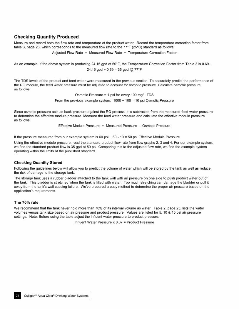
Checking Quantity ProducedMeasure and record both the flow rate and temperature of the product water. Record the temperature correction factor from table 3, page 26, which corresponds to the measured flow rate to the 77°F (25°C) standard as follows:
Adjusted Flow Rate = Measured Flow Rate ÷ Temperature Correction Factor
As an example, if the above system is producing 24.15 gpd at 60°F, the Temperature Correction Factor from Table 3 is 0.69.24.15 gpd ÷ 0.69 = 35 gpd @ 77°F
The TDS levels of the product and feed water were measured in the previous section. To accurately predict the performance of the RO module, the feed water pressure must be adjusted to account for osmotic pressure. Calculate osmotic pressure as follows:
Osmotic Pressure = 1 psi for every 100 mg/L TDSFrom the previous example system: 1000 ÷ 100 = 10 psi Osmotic Pressure
Since osmotic pressure acts as back pressure against the RO process, it is subtracted from the measured feed water pressure to determine the effective module pressure. Measure the feed water pressure and calculate the effective module pressure as follows:
Effective Module Pressure = Measured Pressure - Osmotic Pressure
If the pressure measured from our example system is 60 psi: 60 - 10 = 50 psi Effective Module PressureUsing the effective module pressure, read the standard product flow rate from flow graphs 2, 3 and 4. For our example system, we find the standard product flow is 35 gpd at 50 psi. Comparing this to the adjusted flow rate, we find the example system operating within the limits of the published standard.
Checking Quantity StoredFollowing the guidelines below will allow you to predict the volume of water which will be stored by the tank as well as reduce the risk of damage to the storage tank.The storage tank uses a rubber bladder attached to the tank wall with air pressure on one side to push product water out of the tank. This bladder is stretched when the tank is filled with water. Too much stretching can damage the bladder or pull it away from the tank’s wall causing failure. We’ve prepared a easy method to determine the proper air pressure based on the application’s requirements.
The 70% ruleWe recommend that the tank never hold more than 70% of its internal volume as water. Table 2, page 25, lists the water volumes versus tank size based on air pressure and product pressure. Values are listed for 5, 10 & 15 psi air pressure settings. Note: Before using the table adjust the influent water pressure to product pressure.
Influent Water Pressure x 0.67 = Product Pressure
Performance & Technical Information 25
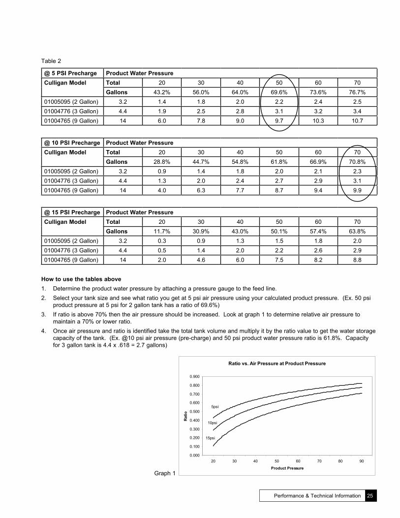
Table 2
@ 5 PSI Precharge Product Water PressureCulligan Model Total 20 30 40 50 60 70
Gallons 43.2% 56.0% 64.0% 69.6% 73.6% 76.7%01005095 (2 Gallon) 3.2 1.4 1.8 2.0 2.2 2.4 2.501004776 (3 Gallon) 4.4 1.9 2.5 2.8 3.1 3.2 3.401004765 (9 Gallon) 14 6.0 7.8 9.0 9.7 10.3 10.7
@ 10 PSI Precharge Product Water PressureCulligan Model Total 20 30 40 50 60 70
Gallons 28.8% 44.7% 54.8% 61.8% 66.9% 70.8%01005095 (2 Gallon) 3.2 0.9 1.4 1.8 2.0 2.1 2.301004776 (3 Gallon) 4.4 1.3 2.0 2.4 2.7 2.9 3.101004765 (9 Gallon) 14 4.0 6.3 7.7 8.7 9.4 9.9
@ 15 PSI Precharge Product Water PressureCulligan Model Total 20 30 40 50 60 70
Gallons 11.7% 30.9% 43.0% 50.1% 57.4% 63.8%01005095 (2 Gallon) 3.2 0.3 0.9 1.3 1.5 1.8 2.001004776 (3 Gallon) 4.4 0.5 1.4 2.0 2.2 2.6 2.901004765 (9 Gallon) 14 2.0 4.6 6.0 7.5 8.2 8.8
How to use the tables above1. Determine the product water pressure by attaching a pressure gauge to the feed line.2. Select your tank size and see what ratio you get at 5 psi air pressure using your calculated product pressure. (Ex. 50 psi
product pressure at 5 psi for 2 gallon tank has a ratio of 69.6%)3. If ratio is above 70% then the air pressure should be increased. Look at graph 1 to determine relative air pressure to
maintain a 70% or lower ratio.4. Once air pressure and ratio is identified take the total tank volume and multiply it by the ratio value to get the water storage
capacity of the tank. (Ex. @10 psi air pressure (pre-charge) and 50 psi product water pressure ratio is 61.8%. Capacity for 3 gallon tank is 4.4 x .618 = 2.7 gallons)
Ratio vs. Air Pressure at Product Pressure
5psi
10psi
15psi
0.000
0.100
0.200
0.300
0.400
0.500
0.600
0.700
0.800
0.900
20 30 40 50 60 70 80 90
Product Pressure
Ratio
Graph 1

26 Culligan® Aqua-Cleer® Drinking Water Systems
Checking EfficiencyMeasure and record the product water flow and the concentrate water flow. Calculate the percent recovery as follows:
Product Water Flow % Recovery = (Product Water Flow + Conc. Water Flow) x 100%
If the concentrate flow rate for the example system is measured at 66 gpd:22 gpd ÷ (22 gpd + 66 gpd) x 100% = 25% Recovery
Table 3 - Temperature Correction Factors (77° F [25° C] rating multiplied by correction factor equals capacity)
Feed Water Temperature Correction Factor
Feed Water Temperature Correction Factor
Feed Water Temperature Correction Factor°F °C °F °C °F °C
36 2 0.33 52 11 0.56 68 20 0.8338 3 0.34 54 12 0.59 70 21 0.8740 4 0.37 56 13 0.63 72 22 0.9042 6 0.40 58 14 0.65 74 23 0.9444 7 0.43 60 16 0.69 76 24 0.9646 8 0.46 62 17 0.72 77 25 1.0048 9 0.50 64 18 0.76 78 26 1.0350 10.0 0.52 66 19 0.79 80 27 1.06
Graph 3Graph 2

Installing an RO to Service Other Water Using Appliances
Pressure, Pressure, PressureIf you are installing a service line from an RO storage tank to an appliance with a minimum pressure requirement then you may need to consider the following options so as not to operate below the operating limits of that appliance. This is important when the appliance has a shutoff that triggers at low or high pressures. The shutoff low value can range from 20 psi all the way up to 35 psi. In an RO storage tank the water pressure will drop when it’s being drained. This reduction in pressure can trigger that shutoff, especially in households where house pressure measures around 40 psi. Graphs 5, 6 and 7 illustrate this drop in pressure when a certain volume of water is drained from a storage tank. To prevent this potential issue we recommend three options. (Figures 18, 19, and 20)
Option 1 - Installation of a demand delivery pump (Figure 18) This type of pump installs after the storage tank, but before the appliance. The pump regulates the line pressure using variable speed technology. A setting inside the electronics package of the pump keeps the line pressure at a set value - usually 60 psi. This pump is more expensive than a standard booster pump, but it offers adaptability to varying water pressure conditions. This adaptability makes it ideal for these types of applications.
Option 2 - Installation of a booster pump (01-0093-34) (Figure 19)Placing this pump before the RO will increases overall pressure to the system. If you boost the water pressure from 40 to 80, then the full pressure in the storage tank will be around 53 psi. Refer to graphs for the draw-down pressures for the 2, 3 and 9 gallon storage tanks. These graphs will guide your sizing decision when installing for this type of application. Increasing the overall pressure in the system will allow more volume to be drawn from the tank before the pressure dips below a shutoff value.
Installation of permeate pump (Figure 20)You can also use the Culligan Permeate Pump (01-0161-83) to increase the pressure inside the storage tank. Installing this non-electric pump in the RO system will increase the pressure inside the tank up to 90% of the incoming water pressure. For example at 80 psi house pressure a standard system would pressurize the tank to 53 psi (80 x 0.67), with a permeate pump that pressure would be closer to 72 psi. This is a low cost alternative that has the potential to meet the application requirements.
To Bottom Of RO Cartridge
Aqua-Cleer Faucet
Ball Valve
Tank
Post Filter
3/8” Tubing to Faucet Product Port
1/4” Tubing to Faucet Airgap
Feedline 1/4” Tubing
Aqua-Cleer Manifold
BoosterPump
DeliveryPump
To Bottom Of RO Cartridge
Aqua-Cleer Faucet
Ball Valve
Tank
Drain
Post Filter
3/8” Tubing to Faucet Product Port
1/4” Tubing to Faucet Airgap
Feedline 1/4” Tubing
Aqua-Cleer Manifold
To Bottom Of RO Cartridge
Aqua-Cleer Faucet
Permeate Pump
Ball Valve
Tank
Post Filter
3/8” Tubing to Faucet Product Port
1/4” Tubing to Faucet Airgap
Feedline 1/4” Tubing
Aqua-Cleer Manifold
Tubing from Faucet Airgap - 3/8” Tubing
Cold Water Supply
Drain
Tubing from Faucet Airgap - 3/8” Tubing
Cold Water Supply
Drain
Tubing from Faucet Airgap - 3/8” Tubing
Cold Water Supply
Performance & Technical Information 27
Figure 18
Figure 19
Figure 20

28 Culligan® Aqua-Cleer® Drinking Water Systems
9 Gallon Tank Pressure vs. DrawdownBoth @ 10psi Pre-Charge
50 psi Tank Pressure
65 psi Tank Pressure
0
10
20
30
40
50
60
70
0 0.53 1.06 1.59 2.11 2.64 3.17 3.70 4.23 4.76 5.28 5.81 6.34
Gallons
PSI
Graph 6
3 Gallon Tank Pressure vs. Drawdown@50psi and 65psi Starting Product Pressure
5psi 10psi5psi 10psi
0
10
20
30
40
50
60
70
0 0.13 0.26 0.53 0.79 1.06 1.32 1.45 1.59 1.72 1.98 2.25
Gallons
PSI
Graph 5
2 Gallon Tank Pressure vs. Drawdown@ 50psi and 65psi Starting Product Pressure
5psi 10psi 5psi 10psi
0
10
20
30
40
50
60
70
0.00 0.06 0.19 0.32 0.44 0.57 0.70 0.82 0.95 1.08 1.20 1.33 1.52
Gallons
PSI
Graph 4

Service & Maintenance
Service & Maintenance 29
Service ScheduleTo keep the Aqua-Cleer® system operating properly, it is necessary to change the filters and sanitize the system periodically. Typically, this should be done on an annual basis. Service frequency may vary depending on local water conditions. High sediment, chlorine, turbidity, or hardness levels may require more frequent service. Use the following as a guide.
As neededClean the faucet with a soft cloth, avoid abrasive cleaners
At least once per yearReplace:
• Particle Filter• Activated Carbon Filter• Polishing Filter
Check:• RO Membrane• Flow control assembly• TDS Reduction Performance• Flow Rates (including air gap)• Drain tubing for back-up
Sanitize the System
Cartridge ConditioningThe activated carbon, reverse osmosis, and polishing filter cartridges must be conditioned as follows prior to installation into the Aqua-Cleer system. Follow the procedures detailed in the “In-Plant Preparation” section of this manual.• Activated Carbon Cartridge - 5 minute flush to remove carbon dust• RO Membrane - Minimum 24 hour flush to remove preservative solution• Polishing Filter - 5 minute flush to remove carbon dust
Materials Needed for Sanitization Procedure• Myron L TDS Monitor (D0470504) • 1/4” X 3/8” coupling - JG• 1/4” pressure gauge (01004228) with needed fittings • 3/8” X 3/8” coupling - JG• Graduated cylinder (00470503) and/or teaspoon measure • 1/4” X 1/4” coupling -JG• Pocket Thermometer (00470501) • Roll of paper towels pan or tray that will hold water• 30 oz (1 liter) container with spout for bleach solution • Syringe and eye dropper for injecting bleach • Clorox Ultra bleach with a safe way of dispensing • Spare parts - tubing o-rings and fittings, faucet stems, etc.• Bypass plugs • Single head cartridge assembly• Sanitizer packet • Sanitizer cartridge
30 Culligan® Aqua-Cleer® Drinking Water Systems
Perform the following steps in the order shown.
Preliminary Steps1. Check for any leaks that may exist from tubing connections or the faucet.2. Check for flow to the drain. If flowing, close tank shut-off so you can check auto shut-off operation3. Test and record product TDS from faucet. Also observe if faucet is in good working order. 4. Test and record feed TDS, then calculate rejection percentage.5. If rejection is acceptable - Shut off storage tank, remove product supply tubing to collect and record product flow, and water
temperature. Collect sample for 1 minute in a graduated cylinder.6. Record feed pressure if needed by attaching a pressure gauge to feed line. Use the recorded feed pressure and water
temperature to check product flow rate against the supplied chart (page 26) and determine if the membrane performace is acceptable. Reconnect the product line. Low production could be the result of partially plugged prefilters. If so retest after filters are changed.
7. With feed supply off begin draining storage tank. When the tank is empty, check the air pre-charge and adjust as required. Air pressure should be 6-8 PSI unless the feed pressure is above 60 PSI or you’re use a booster pump then increase the pressure to be 10 PSI.
Disassembly and Sanitizing Steps1. Remove all filter housings including the membrane and remove the post carbon filter replacing it with a 3/8” coupling. Note:
Water will drain from the fitting on the bottom of the membrane.2. Place 2 tablespoon of bleach into the sanitizer cartridge. Place the sanitizer cartridge in the 1st port in the manifold, then
place bypass plugs in the remaining ports 2,3, and 4 (see Fig. 6b). 3. Turn on the feed line and close the faucet as soon as you get some air spitting from the spout, allowing the sanitizer to fill
into the storage tank. 4. Solution can be flushed through the faucet after 10 minutes. The faucet should be shut off when the flow stops.5. Install new filters, including the post carbon, and membrane if it is needed, or reuse existing membrane. Some filters require
flushing before use to remove dust or fines. If an in-plant flush wasn’t performed use the single head assembly to perform this using the feed line and drain lines available. Don’t flush using the manifold.
Flush and Finish Steps1. Cut the drain tubing just below the flow control and reconnect the tubing to the drain on the membrane housing. 2. Turn on the feed supply and fast flush the system for several minutes. This is beneficial to the membrane and helps to
remove trapped air. 3. Reinstall the flow control from the old piece of tubing or use a new flow control once the system has been flushed. 4. Check air gap operation and the drain tubing for restriction or leaks. 5. If a new membrane was installed, take new product flow measurements and allow more time for rinsing. 6. Replace the battery in the quality monitor if applicable. 7. Clean up your work area.8. Instruct the customer (or leave instructions) to discard the first large glass of water removed from the faucet (or drain the
tank once if membrane was replaced) before using the water. A waiting time isn’t necessary.9. Thoroughly check for leaks - again.

Service & Maintenance 31
Aqua-Cleer® Estimated Flow Rates - Table 4
Temperature °F 35 40 45 50 55 60 65 70 75 80 85
Feed PSI NDP
TCF 2.23 2.03 1.84 1.68 1.52 1.38 1.26 1.14 1.04 0.94 0.86
PCF Product Flow Rate in milliliters per minute25 20.0 2.5 14.1 15.6 17.1 18.8 20.7 22.8 25.1 27.6 30.4 33.4 36.8
30 25.0 2.0 17.7 19.4 21.4 23.5 25.9 28.5 31.3 34.5 37.9 41.8 45.9
35 30.0 1.7 21.2 23.3 25.7 28.2 31.1 34.2 37.6 41.4 45.5 50.1 55.1
40 35.0 1.4 24.7 27.2 29.9 32.9 36.3 39.9 43.9 48.3 53.1 58.5 64.3
45 40.0 1.3 28.3 31.1 34.2 37.7 41.4 45.6 50.2 55.2 60.7 66.8 73.5
50 45.0 1.1 31.8 35.0 38.5 42.4 46.6 51.3 56.4 62.1 68.3 75.2 82.7
55 50.0 1.0 35.3 38.9 42.8 47.1 51.8 57.0 62.7 69.0 75.9 83.5 91.9
60 55.0 0.9 38.9 42.8 47.1 51.8 57.0 62.7 69.0 75.9 83.5 91.9 101.1
65 60.0 0.8 42.4 46.7 51.3 56.5 62.1 68.4 75.2 82.8 91.1 100.2 110.3
70 65.0 0.8 45.9 50.5 55.6 61.2 67.3 74.1 81.5 89.7 98.7 108.6 119.4
75 70.0 0.7 49.5 54.4 59.9 65.9 72.5 79.8 87.8 96.6 106.3 116.9 128.6
80 75.0 0.7 53.0 58.3 64.2 70.6 77.7 85.5 94.0 103.5 113.8 125.3 137.8
85 80.0 0.6 56.5 62.2 68.4 75.3 82.9 91.2 100.3 110.4 121.4 133.6 147.0
90 85.0 0.6 60.1 66.1 72.7 80.0 88.0 96.9 106.6 117.3 129.0 142.0 156.2
95 90.0 0.6 63.6 70.0 77.0 84.7 93.2 102.6 112.8 124.2 136.6 150.3 165.4
100 95.0 0.5 67.1 73.9 81.3 89.4 98.4 108.3 119.1 131.1 144.2 158.7 174.6
Your measured results are acceptable if within 20% of the figures above.Estimated flow to the drain should average about the same as the 75 column and should be almost double that flow rate if fed with hard water above 10 gpg.

Troubleshooting Guide
32 Culligan® Aqua-Cleer® Drinking Water Systems
If a problem cannot be corrected through use of this Troubleshooting Guide and assistance from the factory is required, please have the following information available:
1. Product water flow rate (directly from module).2. Concentrate flow rate (from concentrate water outlet of module housing). Pressure relief valve must be closed when
measuring concentrate flow rate.3. Feed water line pressure.*4. Product water quality (directly from module).*5. Reservoir water quality.*6. Feed water quality.7. Feed water temperature.8. Reservoir precharge pressure.* Check with TDS meter PN D0-4705-04.
Problem Possible Cause Remedy1. Insufficient quantity
of product water available to service.
a. Service greater than unit’s specified output. a. Use optional large tank for more storage capacity.
b. Insufficient feed water flow. b. 1. Clogged shut-off valve or feed tubing; clean out or replace. 2. Clogged prefilter; replace. 3. Clogged manifold; clean or replace.
c. Insufficient feed water pressure c. 1. Same as (b) above. 2. Change in line pressure; install booster pump.
d. Increase in feed water TDS. d. 1. Same as (a) above. 2. Install booster pump.
e. Reduced feed water temperature. e. Same as above.
f. Plugged prefilter. f. Replace filter element.
g. Plugged polishing filter. g. Replace polishing filter.
h. RO membrane fouled with sediment. h. Replace RO membrane and prefilter elements.
i. Shutoff malfunction. i. Clean or replace shutoff.
2. Poor product water quality.
a. All of (1) above except (a) and (e). a. All of (1) above except (a), (e), and (g).
b. RO membrane filter worn out. b. Replace RO membrane.
d. Shutoff malfunction. d. Replace shutoff.
3. Bad tasting product water.
a. Decrease in product quality; see (2) above. a. Same as (2) above.
b. Foreign matter in storage tank. b. Clean, sanitize, and flush storage tank.
c. Polishing filter exhausted. c. Replace polishing filter
d. Plugged capillary tube. d. Replace capillary tube; replace prefilter, if necessary.
e. Storage tank bladder is ruptured. e. Replace storage tank and check precharge pressure.

Troubleshooting Guide 33
Problem Possible Cause Remedy4. External leakage. a. Tubing not fully seated in fitting a. Check all fittings for tightness.
b. Tubing abraded in seal area. b. Recut tubing and redo connection.
5. Overflow at faucet air gap (gurgling sounds).
a. Concentrate tubing plugged. a. Clean concentrate tubing of debris.
b. Air gap plugged. b. Clean with vinegar and/or soap.
c. Concentrate tubing not in continuous downward slope.
c. Eliminate loops or low spots in tubing.
d. Obstructed home drain pipe. d. Free obstruction.
6. Foaming at faucet tip.
a. Storage tank is positioned on side (Dissolved air cannot escape.)
a. Place tank in vertical position.
7. Foaming at air-gap a. Concentrate tubing connected to same drain line as dishwasher, etc.
a. Find different drain for system.
b. When sink is full of soapy water and plug is pulled, can back up at air-gap.
b. Obstructed home drain, free obstruction.
c. Obstructed home drain. c. Free obstruction.
8. Bad smell from product water.
a. Polishing filter exhausted. a. Replace polishing filter.
b. Prefilter element. b. Replace filter element.
c. Unit needs disinfection. c. Sanitize unit.
9. Fast flow to drain. a. Defective flow control assembly. a. Replace flow control assembly.
10. Black specks in product water.
a. Carbon fines. a. Flush polishing filter.
11. Low faucet pressure.
a. Inadequate pre-charge pressure in storage tank.
a. Determine the minimum pressure using the 70% guideline.
b. Polishing filter plugged. b. Replace polishing filter.
12. Flow control plugging.
a. Excessive turbidity. a. Install another 5 micron filter in series with existing one or substitute carbon block filter for granular activated carbon filter.
b. Iron fouled. b. Pretreat for iron removal.
c. Iron-bacteria fouled. c. Sanitize plumbing.

Parts List
34 Culligan® Aqua-Cleer® Drinking Water Systems
Aqua-Cleer Drinking Water System
31
32
30
29
8
5
2
4
3
7
3/8” Outlet
1/4” Inlet
1
15 and 6
18
2 and 3
17
8
7
4
4
9
1213
1516
20
17
21
26
23, 24, and 25
22

Parts List 35
Item Part No. Description Qty. 1 P1-0202-57 Manifold Assm., 6 PK 1
2 P1-00094-13 O-Ring 1/4”, 25 PK 1
3 P1-0044-33 Collar, 1/4”, 25 PK 1
4 P1-0047-13 Push-in Elbow 1/4”, 10 PK 1
5 P1-0094-14 O-Ring 3/8”, 25 PK 1
6 P1-0043-26 Collar, 3/8”, 25 PK 1
7 P1-0047-14 Push-in Elbow 3/8”, 10 PK 1
8 P1-0205-19 O-Ring, 50 PK 4ea/Cartridge
9 P1-0205-21 Flow Control Assembly, 30 GPD, 10 PK (Red) 1
P1-0205-22 Flow Control Assembly, 50 GPD, 10 PK (Black) 1
P1-0205-23 Flow Control Assembly (50% Recovery), 30 GPD, 10 PK (Green)
1
P1-0205-24 Flow Control Assembly (50% Recovery), 30 GPD, 10 PK (Yellow)
1
P1-0207-72Flow Control Assembly (25% Recovery), 30 GPD, 10 PK (Orange)
1
P1-0207-73Flow Control Assembly (25% Recovery), NanoFilter and 50 GPD, 10 PK (White)
1
12 P1-0202-58 Particle Filter Element, SED 1 12 PK 1
P1-0202-60 Particle Filter Element, SED 2, 12 PK
P1-0202-62 Particle Filter Element, SED 3, 12 PK
13 P1-0202-64 Granular Carbon Prefilter, 12 PK 1
P1-0202-66 Carbon Block Prefilter, 12 PK
P1-0223-30 Granular Carbon Large Prefilter, 12 PK
15 P1-0202-68 RO Module, 30 GPD, 12 PK 1
P1-0202-70 RO Module, 50 GPD, 12 PK*
P1-0202-71 RO Module, Nanofilter, 12 PK┼
16 P1-0202-74 Total Defense Cartridge (VOC Reduction), 12 PK 1
P1-0202-72 Arsenic Cartridge, 6 PK 1
P1-0202-73 Perchlorate Cartridge, 6 PK* 1
Item Part No. Description Qty. 17 P1-0205-25 Check Valve Assembly, 10 PK 1
18 P1-0205-26 Front Clip, 10 PK 1
20 P1-0205-28 Rear Clip, 10 PK 1
21 P0-4021-96 Screw #10.9 X 1.00” Phil. Pan Head, 50 PK 3
23 P1-0043-22 O-Ring Large ASV, 10 PK 1
24 P1-0043-21 O-Ring Medium ASV, 10 PK 1
25 P1-0043-20 O-Ring Small ASV, 10 PK 1
27 01-0205-30 Shutoff Cap Assm. (Includes Items 22, 23, 24, 25, 26), 10 PK 1
29 01-0184-01 Faucet, Chrome, Non-Electric 1
01-0084-02 Faucet, White, Non-Electric
01-0186-07 Faucet, Brushed Nickel, Non-Electric
01-0184-68 Faucet, Chrome, Electric
01-0084-69 Faucet, White, Electric
01-0186-04 Faucet, Brushed Nickel, Electric
30 P1-0042-91 GAC Carbon Post Filter 10 Pk 1
01-0047-68 GAC Carbon Post Filter 50 Pk
01-0146-12 Carbon Block Post Filter 10 Pk
01-0146-13 Carbon Block Post Filter 50Pk
* 01-0107-48 Mounting Clip, Polishing Filter
31 01-0045-50 Plastic Ball Valve, .25 NPTFe-male X .375 J. G. 1
32 01-0050-95 Storage Tank (2 Gallon) 1
01-0047-76 Storage Tank (3 Gallon)
01-0047-65 Storage Tank (9 Gallon)
01-0100-64 Storage Tank Stand, Plastic
* 00-4021-84 Tubing, - 1/4” O.D.
01-0002-87 Tubing -3/8” O.D.
* 01-0196-19 Aqua-Cleer Sentry™ Monitor
* P1-0047-15 Tee 3/8 x 3/8 x 3/8 1
* P1-0060-26 Storage Tank Bracket, Steel Gallon Tank, 3 PK
* P1-0040-61 Storage Tank Bracket, Steel Gallon Tank, 3 PK
* P1-0047-28 Icemaker Tee, 3/8”x3/8”x1/4”
* P1-0202-77 Sanitation Cartridge, 6 PK 1
* P1-0203-92 Single Head Assembly, 6 PK 1
* P1-0202-79 Bypass Cartridge, 12 PK 1* Cartridge not for sale in California.┼ Cartridge not for sale in California or Iowa.

36 Culligan® Aqua-Cleer® Drinking Water Systems
Faucet AssemblyItem Part No. Description Qty.
1 - Faucet Housing 1
*2 - Housing O-Ring - 10/PKG 1
*3 - Handle Cartridge 1
*4 - Nut 1
5 - Handle - Single Knob 1
- Handle - Wing 1
6 - Screw 1
7 - Handle Cap 1
8 - Spout 1
*9 - Spout O-Ring (2 req’d) 2
*10 - Spout Clip 1
11 - Spout Nut 1
**12 - Air Gap O-Ring (2 req’d) 2
**13 - Air Gap w/screw 1
14 - Base 1
*15 - Gasket 1
16 - Butterfly Nut 1
*17 - Washer 1
*18 - Spring 1
1901020739
or 01019619
Quality Monitor 1
20 01023022 TDS Flow Switch Kit - 5PK 1
* 01018619 Service Replacement Kit 1
** 01022932 Service Replacement Kit 1
* Included in service replacement kit** Included in service replacement kit
19
16
1
18
5A
6
17
7
4
5B
83910
15
14
13
2
12
11
12
10
20

Worksheet
Worksheet 37
Aqua-Cleer® System Performance Worksheet
Quality Feed Water TDS: TDSFEED __________
Product Water TDS: TDSPROD __________
[(TDSFEED - TDSPROD) ÷ TDSFEED] x 100 = __________% Removal
Quantity Produced Product Water Flow: FPROD ___________
Product Water Temperature: T__________
Temperature Correction Factor: TCF________
FPROD ÷ TCF = __________FCORR (Corrected Product Flow)
Feed Water TDS: TDSFEED __________
(TDSFEED - 500) x 0.014 = __________ POS (Osmotic Pressure)
Feed Water Pressure: PFEED __________
PFEED - POS = __________ PEFF (Effective Pressure)
Read theoretical product flow from graph 2 or 3 at effective pressure, compare to corrected product flow.
Theoretical Product Flow: FTHEOR __________
Quantity Stored Feed Water Pressure: PFEED __________
PFEED x 0.60 = __________PT (Tank Pressure at Shutoff)
Tank Air Pressure: PA __________
Using PT and PA, read the volume of water stored when the shutoff actuates from graph 4, 5, or 6.
Volume Stored: VS __________
Efficiency Product Water Flow: FPROD __________
Concentrate Water Flow: FCONC __________
FP ÷ (FPROD + FCONC) x 100 = __________ % Recovery

38 Culligan® Aqua-Cleer® Technical Manual
Page left intentionally blank.

Chapter 39
text
.31in
.20in
TYP.
5mm
R
2.60mm
R.10in
TYP.
8mm
.31in
80mm
3.15in
43mm
1.69in
5.61in
142.50mm
8mm
65mm
2.56in
80mm
3.15in
.31in
65mm
2.56in
43mm
8mm
1.69in
.31in
.10in
2.60mm
TYP.
5.61in
142.50mm
8mm
R
R5mm
TYP.
.20in
Opening Template - Full Scale
