ctnet file 212
TRANSCRIPT

www.controltechniques.com
EF
User Guide
CTNet
Part Number: 0460-0025-07Issue Number: 7
General InformationThe manufacturer accepts no liability for any consequences resulting from inappropriate, negligent or incorrect installation or adjustment of the optional operating parameters of the equipment or from mismatching the variable speed drive (Drive) with the motor.The contents of this guide are believed to be correct at the time of printing. In the interests of a commitment to a policy of continuous development and improvement, the manufacturer reserves the right to change the specification of the product or its performance, or the contents of this guide, without notice.All rights reserved. No parts of this guide may be reproduced or transmitted in any form or by any means, electrical or mechanical including photocopying, recording or by an information storage or retrieval system, without permission in writing from the publisher.
Drive software versionThis product is supplied with the latest version of user-interface and machine control software. If this product is to be used in a new or existing system with other Drives, there may be some differences between their software and the software in this product. These differences may cause this product to function differently. This may also apply to Drives returned from a Control Techniques Service Centre.If there is any doubt, contact a Control Techniques Drive Centre.
Copyright © 24 March 2005 Control Techniques Drives Ltd.Issue Code: 7Hardware: Rev C and Rev D
Contents1 Electrical Installation 51.1 CTNet network overview 51.2 CTNet hardware revision 61.3 CTNet segment design 71.4 CTNet wiring practices 141.5 CTNet device connections 151.6 CTNet cable 301.7 CTNet segment termination 301.8 CTNet shield connections 311.9 Joining CTNet cables together 331.10 Other wiring tips 35
2 Getting Started 362.1 Unidrive 362.2 Unidrive SP 372.3 Mentor II 372.4 CTNet I/O coupler 382.5 CTNet HMI (CTIU200) 392.6 CTNet Hub 392.7 CTNet PC cards 392.8 Installing PCI and PCMCIA card drivers 402.9 Installing the PC ISA card 41
3 Cyclic Data 423.1 What is cyclic data? 423.2 Cyclic data rate 433.3 Configuring cyclic data links 433.4 “Easy mode” cyclic data 443.5 Mapping conflicts 46
4 Non-Cyclic Data 484.1 Non-cyclic message handling 484.2 Non-cyclic message delays 494.3 Reading parameters over CTNet 494.4 Writing parameters over CTNet 494.5 Check if node exists 49
5 Diagnostics 505.1 CTNet status indication 505.2 CTNet configuration errors 525.3 CTNet advanced diagnostics 535.4 Solving network reconfiguration problems 595.5 Viewing CTNet signals using an oscilloscope 615.6 Overloading a node 63
CTNet User GuideIssue Number: 7 www.controltechniques.com

6 Advanced Features 656.1 Automatic sync node assignment 656.2 Editing cyclic data links 656.3 Enabling and disabling cyclic data links 656.4 EVENT task trigger on UD70 666.5 EVENT task trigger on SM-Applications 676.6 CTNet priority level on SM-Applications 67
7 Legacy CTNet Hardware 687.1 Basic segment limitations 687.2 CTNet wiring practices 697.3 Mixing CTNet hardware 697.4 CTNet drivers for Windows 95 70
CTNet User Guidewww.controltechniques.com Issue Number: 7

1 Electrical Installation1.1 CTNet network overview
A CTNet network comprises of one or more segments that are linked together by a hub. A typical layout of a CTNet network is shown in Figure 1-1. Each segment has a termination resistor fitted at each end, and each segment meets the limits specified in section 1.3 CTNet segment design on page 7.
Figure 1-1 Example CTNet network layout
Table 1.1 CTNet network terminology
Term Definition
network One or more segments joined together using hubs to extend the total cable length and/or increase the total number of nodes on the network.
segmentTwo or more nodes connected to a length of CTNet cable, with an 82Ω 1% 0.25W termination resistor fitted at each end. The cable must run from node to node as drop lengths are not permitted on CTNet.
trunk cableThe length of cable that connects nodes together to create a segment. The trunk cable must run from node-to-node-to-node; drop lengths of cable are not allowed on a CTNet segment.
termination resistor
82Ω 1% 0.25W resistors that must be connected between the data lines (“A” and “B”) at the end of each segment to prevent pulse reflections. A termination resistor should be fitted if there is only one CTNet cable going to a node.
Segment 1
Segment 3
Segment 2
indicates position of termination resistors
CTNet User Guide 5Issue Number: 7 www.controltechniques.com

1.2 CTNet hardware revisionAll new CTNet devices are marked with a hardware revision level. Rev D is the up-to-date hardware revision, but some devices have the intermediate Rev C hardware fitted. All Rev C devices will eventually be updated to incorporate the Rev D hardware.
1.2.1 Revision D hardwareCTNet Rev D hardware has been introduced to improve the overall performance of CTNet, and all Rev D devices are marked with the new CTNet conformance logo. Rev D hardware uses an improved output
driver stage to give higher voltage pulses, and a higher impedance input stage to reduce the load applied to the network by each node. The overall effect is to increase the number of nodes and/or total length of cable that be used for a single network segment. The maximum permitted cable length can also be increased by reducing the number of nodes on a segment, and vice versa.
active node
Active nodes produce an electrical load on the segment, and require a node address to be assigned, as they take part in the token ring bus arbitration system. The maximum number of active nodes that can be connected on a CTNet network is 255.
passive node
Passive nodes produce an electrical load on the segment, but do not require a node address to be assigned as they do not take part in the token ring bus arbitration system. They must be included when considering the number of nodes connected to a segment.
drop lengthA branch or spur of cable (terminated or unterminated) off the main trunk run, not allowed on a CTNet network. A drop length is present if there are 3 or more CTNet cables connected to a single node.
Table 1.1 CTNet network terminology
Term Definition
Table 1.2 CTNet Rev C and Rev D hardware devices
Device Reference code RevisionUnidrive CTNet,Unidrive,UD75,Rev D 80700000005701
Unidrive SP SM-Applications (All modules have Rev D CTNet hardware) All
Mentor II CTNet,Mentor,MD29AN,Rev D 80100000006201CTNet I/O Coupler CTNet,BK7200 I/O Coupler,Rev C 4500-0089
CTIU200 CTNet,CTIU,SmartStack Rev C 4500-0088Hub CTNet, 3 Port Hub,Rev D 4500-0082
PCI card CTNet,PCI Card,Rev D 4500-0085
PCI/PCIX card CTNet,PCI/PCIX Card, Rev D, replaces 4500-0085 4500-0085-1
PCMCIA card CTNet,PCMCIA Card+MAU,Rev D 4500-0086PC ISA card CTNet,ISA Card,Rev D 4500-0084Hybrid Hub CTNet,3 Port Hybrid Hub,Rev D 4500-0083
Fibre Optic Repeater CTNet,Fib Optic Repeater,Rev D 4500-0081CTNet MAU only CTNet,PCMCIA MAU only,Rev D 4500-0090
If a device and revision level is not listed in Table 1.2, refer to section 7 Legacy CTNet Hardware on page 68.
NOTE
N
6 CTNet User Guidewww.controltechniques.com Issue Number: 7

Rev D hardware allows a mathematical model to be applied to a segment design to determine if the combination of nodes and cable length is within the CTNet specifications for the required data rate. The model covers data rates of 5.0 Mbit/s, 2.5 Mbit/s and 1.25 Mbit/s. The table below gives some example specifications that can be met with a segment consisting entirely of CTNet Rev D hardware devices.
1.2.2 Revision C hardwareCTNet Rev C hardware uses identical output driver and input receiver stages as Rev D hardware, but it uses the old CTNet pulse transformer. The lower inductance of the old-style pulse transformer means that
fewer Rev C nodes can be connected to a CTNet segment than Rev D devices. Rev C and Rev D devices can be mixed on a network segment without problem, but the higher loading factor of Rev C hardware must be taken in to account when checking the overall design of the CTNet segment. (See section 1.3.1 for full details.)
1.3 CTNet segment designIn an ideal world, the CTNet transmitter stage would have zero output impedance, CTNet cable would have zero resistance, capacitance and inductance, and CTNet receiver stages would have infinite input impedance. This would allow any number of nodes to be connected to a segment of any length. Unfortunately, as with all real-world communication systems, this is not the case.A CTNet segment has limitations on the number of nodes and total length of cable that can be connected. In general, more nodes means less cable and vice versa, so the arrangement of segment and placement of hubs needs to be carefully considered when designing the network.The configuration of a CTNet network can be checked by calculating the Segment Load Factor (KSL) and Insertion Loss Factor (KIL) for each segment. If both KSL and KIL are within specifications for ALL segments, the CTNet network will run without problem.
All devices connected to a segment MUST be Rev C or Rev D hardware to use the Segment Loss Factor (KSL) and Insertion Loss Factor (KIL) equations and graphs. All CTNet Rev C and Rev D devices are listed in Table 1.2.
Table 1.3 Example segment specifications
Data rate (Mbit/s)Total cable length (m)
5 nodes 10 nodes 15 nodes 20 nodes5.0 140 100 75 442.5 250 200 150 100
1.25 340 275 200 135
N
It is possible that a network configuration that is outside the specified limits may work without any apparent problem. However, Control Techniques will not guarantee reliable operation of a CTNet network if it does not comply to all specifications listed in this manual. Such a network is also likely to be sensitive to electrical interference.
NOTE
CTNet User Guide 7Issue Number: 7 www.controltechniques.com

1.3.1 Segment Load FactorThe Segment Load Factor determines the maximum number of nodes that can be connected on a single segment of network, irrespective of network length.
where:KSL =Segment Load Factor.
NRevD =total number of Rev D devices on the network segment.
KRevD =load factor for a single Rev D device for a given data rate.
NRevC =total number of Rev C devices on the network segment.
KRevC =load factor for a single Rev C device for a given data rate.
The maximum permitted values of KSL are given in Figure 1.4.
To check that the Segment Load Factor (KSL) is suitable for a given CTNet segment arrangement:1. Specify the network data rate.2. Determine the total number of Rev C (NRevC) and Rev D devices. (NRevD)3. Plot the point on the Segment Load Factor Graph (Figure 1-2) where NRevD and
NRevC intersect.4. If the point of intersection is above the plotted line for the specified data rate, the
Segment Load Factor is too high, and CTNet operation cannot be guaranteed. Split the segment (using a hub) and repeat steps 1 to 3 for each segment.
5. If the point of intersection is on or below the plotted line for the specified data rate, the Segment Load Factor is within the specified limits. Check the Insertion Loss Factor to see if segment arrangement is valid. (See section 1.3.2.)
When calculating the Segment Load Factor and Insertion Loss Factors, each connected hub and repeater port must be counted as a node for that segment.
Table 1.4 Segment Load Factors
Data Rate (Mbit/s)
Maximum Segment Load
Factor (KSL)
Rev D Device Load Factor
(KRevD)
Rev C Device Load Factor
(KRevC)
1.25 100 5.00 9.092.5 100 3.29 6.095.0 100 0.53 0.97
NOTE
KSL NRevD KRevD×( ) NRevC KRevC×( )+=
8 CTNet User Guidewww.controltechniques.com Issue Number: 7

Figure 1-2 Segment Load Factor graph
At 5.0 Mbit/s, the calculation shows that 188 Rev D or 100 Rev C nodes could be connected to a single segment, but this will be limited by the Insertion Loss Factor. (See section 1.3.2.) As the Segment Load Factor is not a limiting factor at 5.0 Mbit/s, this line is not plotted in Figure 1-2, allowing a clearer scale to be used for the 2.5 Mbit/s and 1.25 Mbit/s data rates.
Segment Load Factor (KSL)
0
2
4
6
8
10
12
14
16
18
20
22
24
26
28
30
0 2 4 6 8 10 12 14 16
Total Number of Rev C Nodes (NRevC)
Tota
l Num
ber o
f Rev
D N
odes
(NR
evD)
2.5 Mbit/s
1.25 Mbit/s
NOTE
CTNet User Guide 9Issue Number: 7 www.controltechniques.com
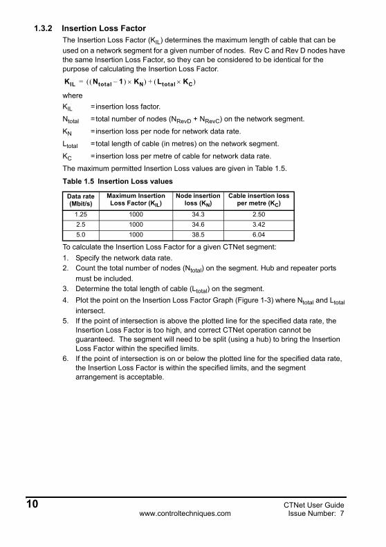
1.3.2 Insertion Loss FactorThe Insertion Loss Factor (KIL) determines the maximum length of cable that can be used on a network segment for a given number of nodes. Rev C and Rev D nodes have the same Insertion Loss Factor, so they can be considered to be identical for the purpose of calculating the Insertion Loss Factor.
whereKIL = insertion loss factor.
Ntotal = total number of nodes (NRevD + NRevC) on the network segment.
KN =insertion loss per node for network data rate.
Ltotal = total length of cable (in metres) on the network segment.
KC =insertion loss per metre of cable for network data rate.
The maximum permitted Insertion Loss values are given in Table 1.5.
To calculate the Insertion Loss Factor for a given CTNet segment:1. Specify the network data rate.2. Count the total number of nodes (Ntotal) on the segment. Hub and repeater ports
must be included.3. Determine the total length of cable (Ltotal) on the segment.4. Plot the point on the Insertion Loss Factor Graph (Figure 1-3) where Ntotal and Ltotal
intersect.5. If the point of intersection is above the plotted line for the specified data rate, the
Insertion Loss Factor is too high, and correct CTNet operation cannot be guaranteed. The segment will need to be split (using a hub) to bring the Insertion Loss Factor within the specified limits.
6. If the point of intersection is on or below the plotted line for the specified data rate, the Insertion Loss Factor is within the specified limits, and the segment arrangement is acceptable.
Table 1.5 Insertion Loss values
Data rate (Mbit/s)
Maximum Insertion Loss Factor (KIL)
Node insertion loss (KN)
Cable insertion loss per metre (KC)
1.25 1000 34.3 2.502.5 1000 34.6 3.425.0 1000 38.5 6.04
KIL Ntotal 1–( ) KN×( ) Ltotal KC×( )+=
10 CTNet User Guidewww.controltechniques.com Issue Number: 7

Figure 1-3 Insertion Loss Factor graph
Insertion Loss Factor (KIL)
0
50
100
150
200
250
300
350
400
2 4 6 8 10 12 14 16 18 20 22 24 26 28 30
Total Number of Nodes (Ntotal)
Max
imum
Seg
men
t Len
gth
(Lto
tal)
in m
etre
s5.0 Mbit/s
2.5 Mbit/s
1.25 Mbit/s
CTNet User Guide 11Issue Number: 7 www.controltechniques.com

1.3.3 Propagation Delay FactorElectrical pulses and light pulses in a glass fibre optic cable take approximately 5ns to travel along 1m of cable, and can take up to 320ns to travel through a hub or repeater. When Node A transmits a token, it will wait for a defined period of time (called “Response Time”) to see some transmission activity on the network, indicating that Node B has received the token and taken control of the network.The critical path is the longest possible path (in terms of cable length and number of hubs/repeaters in the path) between any 2 nodes on the network. If a fibre optic link is used on the CTNet network, the length of the fibre optic link must also be taken into account. The maximum propagation delay experienced on this critical path must be less than the Response Time, or there is a possibility that the Node A will start transmitting again, BEFORE the signals from the Node B have propagated back through the cable and hubs. In this case, there will be a collision, i.e. 2 nodes transmitting at the same time, and network errors will be seen.In general, the Propagation Delay Factor only becomes a limiting factor when fibre optic links are used to extend the network to lengths that cannot be achieved using copper cable. However, all networks should be checked to ensure that the maximum Propagation Delay Factor is not exceeded.
whereKPD =maximum propagation delay factor.
NRep =total number of hubs/repeaters in the network.
LNet =total length of copper and fibre optic cable (in metres) in the critical path.
The maximum permitted propgation delay factors are given in Table 1.6.
To calculate the Propagation Delay Factor (KPD) for a given CTNet network:
1. Specify the network data rate.2. Count the total number of hubs and repeaters (NRep) on the network.3. Determine the total length of copper and fibre optic cable (LNet) in the critical path.4. Plot the point on the Propagation Delay Factor graph (Figure 1-4) where NRep and
LNet intersect.5. If the point of intersection is above the plotted line for the specified data rate, the
Propagation Delay Factor is too high, and the CTNet network design is not possible at that data rate.
6. If the point of intersection is on or below the plotted line for the specified data rate, the Propagation Delay Factor is within the specified limits, and the network arrangement will be OK.
Table 1.6 Maximum Propagation Delay Factor
Data rate (Mbit/s)
Maximum Propagation Delay Factor (KPD)
1.25 120002.5 60005.0 3000
KPD 64 NRep×( ) LNet+=
12 CTNet User Guidewww.controltechniques.com Issue Number: 7

Figure 1-4 Propagation Delay Factor graph
Propagation Delay Factor (KPD)
0
1,000
2,000
3,000
4,000
5,000
6,000
7,000
8,000
9,000
10,000
11,000
12,000
0 2 4 6 8 10 12 14 16 18 20
Total Number of Hubs and Repeaters (NRep)
Max
imiu
m N
etw
ork
Leng
th (L
tota
l) in
met
res
5.0 Mbit/s
2.5 Mbit/s
1.25 Mbit/s
CTNet User Guide 13Issue Number: 7 www.controltechniques.com
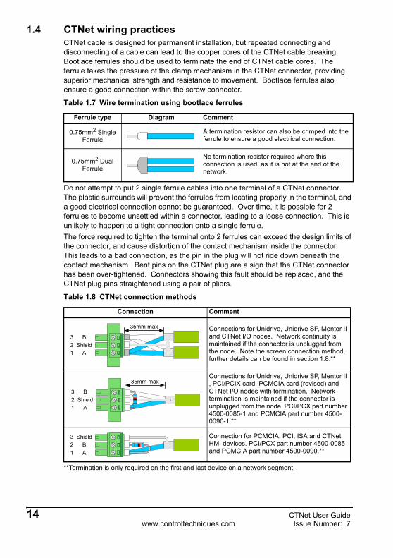
1.4 CTNet wiring practicesCTNet cable is designed for permanent installation, but repeated connecting and disconnecting of a cable can lead to the copper cores of the CTNet cable breaking. Bootlace ferrules should be used to terminate the end of CTNet cable cores. The ferrule takes the pressure of the clamp mechanism in the CTNet connector, providing superior mechanical strength and resistance to movement. Bootlace ferrules also ensure a good connection within the screw connector.
Do not attempt to put 2 single ferrule cables into one terminal of a CTNet connector. The plastic surrounds will prevent the ferrules from locating properly in the terminal, and a good electrical connection cannot be guaranteed. Over time, it is possible for 2 ferrules to become unsettled within a connector, leading to a loose connection. This is unlikely to happen to a tight connection onto a single ferrule.The force required to tighten the terminal onto 2 ferrules can exceed the design limits of the connector, and cause distortion of the contact mechanism inside the connector. This leads to a bad connection, as the pin in the plug will not ride down beneath the contact mechanism. Bent pins on the CTNet plug are a sign that the CTNet connector has been over-tightened. Connectors showing this fault should be replaced, and the CTNet plug pins straightened using a pair of pliers.
**Termination is only required on the first and last device on a network segment.
Table 1.7 Wire termination using bootlace ferrules
Ferrule type Diagram Comment
0.75mm2 Single Ferrule
A termination resistor can also be crimped into the ferrule to ensure a good electrical connection.
0.75mm2 Dual Ferrule
No termination resistor required where this connection is used, as it is not at the end of the network.
Table 1.8 CTNet connection methods
Connection Comment
Connections for Unidrive, Unidrive SP, Mentor II and CTNet I/O nodes. Network continuity is maintained if the connector is unplugged from the node. Note the screen connection method, further details can be found in section 1.8.**
Connections for Unidrive, Unidrive SP, Mentor II , PCI/PCIX card, PCMCIA card (revised) and CTNet I/O nodes with termination. Network termination is maintained if the connector is unplugged from the node. PCI/PCX part number 4500-0085-1 and PCMCIA part number 4500-0090-1.**
Connection for PCMCIA, PCI, ISA and CTNet HMI devices. PCI/PCX part number 4500-0085 and PCMCIA part number 4500-0090.**
ShieldB
A
35mm max
23
1
35mm max
ShieldB
A23
1
BShield
A23
1
14 CTNet User Guidewww.controltechniques.com Issue Number: 7

Although CTNet data lines are marked “A and “B”, it does not matter which way round the wires are connected, provided one wire from each cable goes to “A” and the other data wire goes to “B”. This simplifies matters when wiring up a CTNet network.
1.5 CTNet device connections1.5.1 Unidrive (UD75-CTNet)
The UD75-CTNet module fits into the large option module slot under the Unidrive keypad. The D-type connectors are the UD70 RS232 programming port (Port C) and the UD70 general purpose RS485 communications port and high speed digital I/O. (Port D) CTNet connections are made using the 3-pin connector at Port A.
Figure 1-5 UD75-CTNet module
The cable screen should be connected to the CTNet Shield pin, but should also be clamped to earth before it gets to the Unidrive. (See section 1.8.)The UD75-CTNet module does not have an internal CTNet termination resistor fitted.
Table 1.9 UD75-CTNet module connections
Pin Function Pin FunctionA1 CTNet A D1 RS485 0V isolated
A2 CTNet shield D2 RS485 /Tx (TxA)
A3 CTNet B D3 RS485 /Rx (RxA)C2 RS232 Rx D4 Digital input 0C3 RS232 Tx D5 Digital input 1C5 Digital 0V D6 RS485 Tx (TxB)
D7 RS485 Rx (RxB)D8 Digital output 0D9 Digital 0V
A
DC
B
CTNet User Guide 15Issue Number: 7 www.controltechniques.com

1.5.2 Unidrive SP (SM-Applications)The CTNet module for the Unidrive SP is the SM-Applications. It can be fitted into any of the 3 expansion slots available on the Unidrive SP.
Figure 1-6 SM-Applications
The additional terminals are the general purpose RS485 communications port (pins 1 to 5) and the high speed digital I/O terminals. (Pins 9 to 13)The cable screen should be connected to the CTNet shield pin, but should also be clamped to earth before it gets to the Unidrive SP. The grounding backet on the Unidrive SP is provided for this purpose. (See section 1.8.) The SM-Applications does not have an internal termination resistor fitted.
Table 1.10 SM-Applications connections
Pin Function Pin Function1 RS485 isolated 0V 9 Digital 0V2 RS485 /Rx (RxA) 10 Digital input 03 RS485 Rx (RxB) 11 Digital input 14 RS485 /Tx (TxA) 12 Digital output 05 RS485 Tx (TxA) 13 Digital output 16 CTNet A
7 CTNet shield
8 CTNet B
RS485 port
1 5 139
High speeddigital I/OCTNet port
6 8
16 CTNet User Guidewww.controltechniques.com Issue Number: 7

1.5.3 Mentor II (MD29AN)The Mentor II CTNet card (MD29AN) fits onto the 40 pin header (PL1) on the MDA2B terminal board of the Mentor II. The D-type connectors are the MD29 RS232 programming port (SK2) and the MD29 general purpose RS485 communications port and high speed digital I/O. (PL1) CTNet connections are made using the 3-pin connector (PL2). The MD29AN does not have an internal CTNet termination resistor fitted.
Figure 1-7 MD29AN
The cable screen should be connected to the CTNet shield pin, but should also be clamped to earth before it gets to the Mentor II. (See section 1.8.)
Table 1.11 MD29AN connections
Pin Function Pin FunctionPL2.1 CTNet A PL1.1 RS485 0V isolated
PL2.2 CTNet shield PL1.2 RS485 /Tx (TxA)
PL2.3 CTNet B PL1.3 RS485 /Rx (RxA)SK2.2 RS232 Tx PL1.4 Digital input 0SK2.3 RS232 Rx PL1.5 Digital input 1SK2.5 Digital 0V PL1.6 RS485 Tx (TxB)
PL1.7 RS485 Rx (RxB)PL1.8 Digital output 0PL1.9 Digital 0V
MD29AN ISS.03.00
RS485 CTNet RS232
CTNet User Guide 17Issue Number: 7 www.controltechniques.com
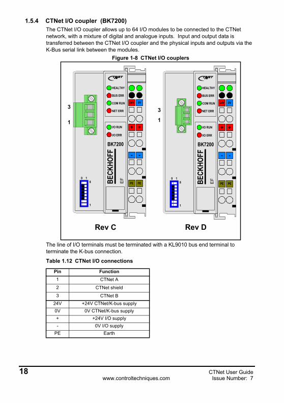
1.5.4 CTNet I/O coupler (BK7200)The CTNet I/O coupler allows up to 64 I/O modules to be connected to the CTNet network, with a mixture of digital and analogue inputs. Input and output data is transferred between the CTNet I/O coupler and the physical inputs and outputs via the K-Bus serial link between the modules.
Figure 1-8 CTNet I/O couplers
The line of I/O terminals must be terminated with a KL9010 bus end terminal to terminate the K-bus connection.
Table 1.12 CTNet I/O connections
Pin Function1 CTNet A
2 CTNet shield
3 CTNet B24V +24V CTNet/K-bus supply0V 0V CTNet/K-bus supply+ +24V I/O supply- 0V I/O supply
PE Earth
24V
+
-
PE
0V
+
-
PEBECK
HOFF
N
HEALTHY
BUS ERR
I/O ERR
NET ERR
I/O RUN
COM RUN
BK7200
EF0 1
1
8
3
1
Rev DRev C
24V
+
-
PE
0V
+
-
PEBECK
HOFF
N
HEALTHY
BUS ERR
I/O ERR
NET ERR
I/O RUN
COM RUN
BK7200
EF0 1
1
8
3
1
18 CTNet User Guidewww.controltechniques.com Issue Number: 7

The cable screen should be connected to the CTNet shield pin, but should also be clamped to earth before it gets to the CTNet I/O coupler. (See section 1.8.) The CTNet I/O coupler does not have an internal termination resistor fitted.
Each I/O module will have a specified current consumption from the K-Bus. If the total continuous current of the CTNet I/O coupler and K-bus exceeds 500mA, a K-bus power supply unit terminal (KL9400) can be used to supply rest of the K-bus.Analogue and digital input and output modules are connected to the right hand side of the CTNet I/O boupler. Up to 64 I/O modules can be connected in any combination, subject to the limitations listed in Table 1.14.
* - firmware V1.03.00 must be fitted to support 512 digital inputs or outputs.
Table 1.13 Operating specifications
Input voltage 24V DC +/-20%Continuous current 70mA + (total K-Bus current)/4
Max continuous current 500mAStarting current 2.5 * continuous current
Operating temperature 0°C to +50°C
Table 1.14 CTNet I/O coupler input and output limitations
Terminal group Max modules I/ODigital Input 64 512*
Digital Output 64 512*Analogue Input 50 100
Analogue Output 50 100
CTNet User Guide 19Issue Number: 7 www.controltechniques.com

1.5.5 CTNet HMI (CTIU200)The CTNet HMI provides an operator interface to allow data display, editing and control facilities for a machine via CTNet. All CTNet settings are configured using the CTIU Configurator package. The CTIU200 must be fitted with the CTNet SmartStack module to allow it to communicate over CTNet.
Figure 1-9 CTNet HMI
Figure 1-10 SmartStack module
F9 F10 F11 F12 F13
F18F17F16F15F14
F5
F6
F7
F8
F1
F2
F3
F4
1QZ_
2ABC
3DEF
6MNO
4GHI
5JKL
7PRS
8TUV
9WXY
+/-Space
100
Del
NEXTALARMACCEPT
WJ
1 2 31 - A2 - B3 - ShieldN
13 18
J1 AutomationEquipment Port CTNet Port
PowerSupply J3
PC PortJ2
SmartStackModuleJ6
13
13
N 1 2 31 - CTNet A2 - CTNet B3 - ShieldRev C
20 CTNet User Guidewww.controltechniques.com Issue Number: 7

The cable screen should be connected to the CTNet shield pin, but should also be clamped to earth before it gets to the CTNet HMI. (See section 1.8.) The pin connections for each connector are given in Table 1.15. There is no internal termination resistor fitted.
Table 1.15 CTNet HMI connections
Pin Function Pin FunctionJ1-1 Earth J3-1 RS485 Tx+J1-2 0V Supply J3-2 RS485 Tx-J1-3 +24V Supply J3-3 RS485 Rx+J2-2 Tx J3-4 RS485 Rx-J2-3 Rx J3-5 RS232 TxDJ2-5 0V J3-6 RS232 GNDJ6-1 CTNet A J3-7 RS232 RxD
J6-2 CTNet B J3-8 EarthJ6-3 CTNet Shield
CTNet User Guide 21Issue Number: 7 www.controltechniques.com
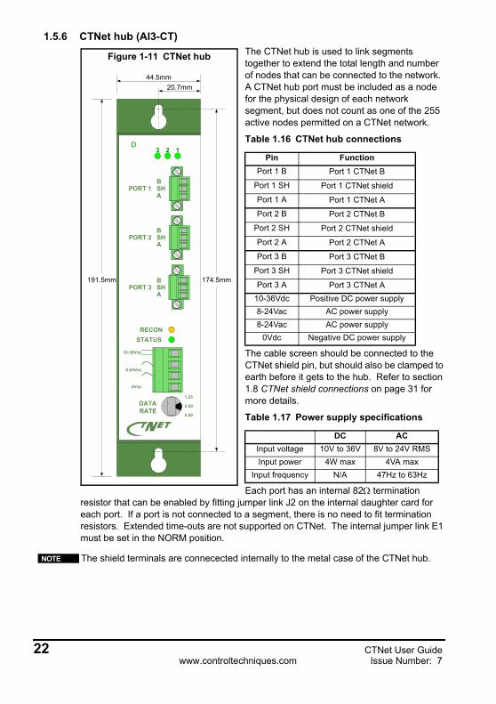
1.5.6 CTNet hub (AI3-CT)The CTNet hub is used to link segments together to extend the total length and number of nodes that can be connected to the network. A CTNet hub port must be included as a node for the physical design of each network segment, but does not count as one of the 255 active nodes permitted on a CTNet network.
The cable screen should be connected to the CTNet shield pin, but should also be clamped to earth before it gets to the hub. Refer to section 1.8 CTNet shield connections on page 31 for more details.
Each port has an internal 82Ω termination resistor that can be enabled by fitting jumper link J2 on the internal daughter card for each port. If a port is not connected to a segment, there is no need to fit termination resistors. Extended time-outs are not supported on CTNet. The internal jumper link E1 must be set in the NORM position.
Table 1.16 CTNet hub connections
Pin FunctionPort 1 B Port 1 CTNet B
Port 1 SH Port 1 CTNet shield
Port 1 A Port 1 CTNet A
Port 2 B Port 2 CTNet B
Port 2 SH Port 2 CTNet shield
Port 2 A Port 2 CTNet A
Port 3 B Port 3 CTNet B
Port 3 SH Port 3 CTNet shield
Port 3 A Port 3 CTNet A10-36Vdc Positive DC power supply8-24Vac AC power supply8-24Vac AC power supply
0Vdc Negative DC power supply
Table 1.17 Power supply specifications
DC ACInput voltage 10V to 36V 8V to 24V RMSInput power 4W max 4VA max
Input frequency N/A 47Hz to 63Hz
The shield terminals are connecected internally to the metal case of the CTNet hub.
D
RECON
DATARATE
N
3 2 1
PORT 2 SHB
A
PORT 1 SHB
A
PORT 3 SHB
A
STATUS
10-36Vdc
8-24Vac
0Vdc
20.7mm44.5mm
174.5mm191.5mm
2.50
1.25
5.00
Figure 1-11 CTNet hub
NOTE
22 CTNet User Guidewww.controltechniques.com Issue Number: 7

The CTNet hub, hybrid hub (see section 1.5.10 CTNet hybrid hub (AI3-485X-CT) on page 28) and fibre optic repeater (see section 1.5.11 CTNet fibre optic repeater (AI2-CT/FOG-ST) on page 29) can be powered from an AC or a DC supply, or a combination of both to ensure continued operation in the event of power supply failure.
Table 1.18 CTNet Hub general specification
Characteristic SpecificationOperating temperature 0°C to +60°CStorage temperature -40°C to +85°CCompliance ANSI/ATA 878.1Delay time 320 ns maximumUnlatch delay time 5.9 µs @ 2.5 Mbit/sRegulatory compliance CE Mark FCC Part 15 Class A
Table 1.19 CTNet Hub power supply connections
Power supply Connections Description
DC power supply The power supply input connections are reverse voltage protected.
Redundant DC power supply
Each power supply must be capable of supplying the AI3-CT by itself. Input currents will not necessarily be balanced from the two supplies.
AC power supply The secondary winding of the transformer must not be earthed.
AC power supply with earthed secondary
For use when the secondary winding of the transformer is earthed.
AC power supply with battery backup
The AC RMS voltage must be higher than the battery voltage to ensure that power is drawn from the AC supply in normal operation. External provision must be made to charge the batteries when AC power is present.
+
+ +
+
CTNet User Guide 23Issue Number: 7 www.controltechniques.com

1.5.7 CTNet PCI cards 4500-0085 and 4500-0085-1There are two different versions of the PCI card the 4500-0085 is the PCI only card and the 4500-0085-1 is the card that supports PCI and the newer PCIX standard. The 4500-0085 has now been superceded and is replace with the 4500-0085-1 card which can be easilly identified as the CTNet connector has screw-locks fitted.
Figure 1-12 CTNet PCI card (4500-0085)
The cable screen should be connected to the CTNet shield pin, but should also be clamped to earth before it gets to the CTNet PCI Card. (See section 1.8 CTNet shield connections on page 31.) A good earth connection cannot be guaranteed if the screen is simply connected to the PCI20-CT card, as the earth connection relies on contact between metallic surfaces within the PC. If any of these surfaces are painted, there may be no earth connection at all.The card has an internal 82Ω termination resistor that can be enabled by fitting jumper link J2 on the internal daughter card. The internal termination resistor should only be used if the card is connected at the end of a network segment. The two cards have different connector layouts, the newer card has been altered to match the drive connections in order to simplify inter-connection..
Table 1.20 CTNet PCI card connections
Pin 4500-0085 4500-0085-11 CTNet A CTNet A2 CTNet B Shield3 Shield CTNet B
1
PCI20
J2
N
3
24 CTNet User Guidewww.controltechniques.com Issue Number: 7

Table 1.21 CTNet PCI card general specifications
Characteristic SpecificationOperating temperature 0°C to +60°CStorage temperature -40°C to +85°CDimensions 107mm x 140mmCompatibility Compliant with ANSI/ATA 878.1 and PCI bus computers
CTNet User Guide 25Issue Number: 7 www.controltechniques.com

1.5.8 CTNet PCMCIA card (PCM20H-CT)The PCM20H-CT kit consists of a PCM20H PCMCIA card and a MAU20H-CT Media Access Unit (MAU) with the CTNet hardware. The PCM20H card can be fitted to any PC with a spare PCMCIA slot, allowing an application running on the PC to access data from the nodes connected to the CTNet network. SYPT, CTSoft and the OPRC Server can all communicate with CTNet via the PCM20H-CT card.
Figure 1-13 CTNet PCMCIA card and MAU types
Figure 1-13 shows the two different MAU types. The 4500-0090 is shown on the left and has no retaining screws on the connector. The 4500-0090-1 is shown on right and has retaining screws on the connector for securing the network cabling.The internal 82Ω termination resistor is disabled by default, and should not be used as there is a risk of damaging the MAU when it is dismantled. The PCM20H-CT card is also generally used for temporary network connections, e.g. using SYPT for system commissioning, and may leave a segment unterminated when disconnected.
Table 1.22 CTNet PCMCIA card connections
PinPart Number
4500-0090Connections
Part Number 4500-0090-01Connection
1 CTNet A CTNet A2 CTNet B Shield3 Shield CTNet B
A PCM20H card with Contemporary Controls labelling is functionally identical to a PCM20H card with Control Techniques labelling. The CTNet MAU (MAU20H-CT) actually contains the CTNet hardware, and is different to the Contemporary Controls MAU. The CTNet MAU can be used with a Control Techniques or a Contemporary Controls PCM20H card, and is available as a separate item from Control Techniques to update a PCMCIA kit to Rev D. The part number 4500-0090 and 4500-0090-01 have different electrical connections that are detailled above.
EFPCM20H
PCMCIA CardAdapterN
DMAU20H-CT
Media Access UnitN
3
1
4500-0090
EFPCM20H
PCMCIA CardAdapterN
DMAU20H-CT
Media Access UnitN
3
1
4500-0090-1
NOTE
26 CTNet User Guidewww.controltechniques.com Issue Number: 7

The PCM20H conforms to release 2.1 of the PC card standard Type II (5.0 mm thick) cards.
1.5.9 CTNet PC ISA card (PCX20-CT)The PCX20-CT card can be fitted to any PC with a spare ISA slot. This allows a PC application program to access data from the nodes connected to the CTNet network. SYPT, CTSoft and CTSoft can all communicate with CTNet via the PCX20-CT card.
Figure 1-14 CTNet PC ISA card
The cable shield must be clamped directly to earth before it reaches the PCX20-CT card. A good earth connection cannot be guaranteed if the screen is simply connected to the PCX20-CT card, as the earth connection relies on contact between metallic surfaces. If any of these surfaces are painted, there may be no earth connection at all.The PCX20-CT card has an internal 82Ω termination resistor that can be enabled by fitting jumper link J2 on the internal daughter card. This resistor should only be used if the PCX20-CT card is connected at the end of a network segment.
Table 1.23 CTNet PCMCIA card general specification
Characteristic SpecificationOperating temperature 0°C to +55°CStorage temperature -20°C to +65°CDimensions (PCMCIA card) 85mm x 54mm x 5mmDimensions (MAU) 81mm x 46mm x 26mmDimensions (cable length) 283mmCompatibility Compliant with ANSI/ATA 878.1 and PC Card
Table 1.24 CTNet PC ISA card connections
Pin Connection1 CTNet A2 CTNet B3 Shield
CCSI PCX20
J2
N
IRQ E1
2/9 3 4 5 6 7
E2 AD
DR
A4
A5
A6
A7
A8
A9
3
1
CTNet User Guide 27Issue Number: 7 www.controltechniques.com
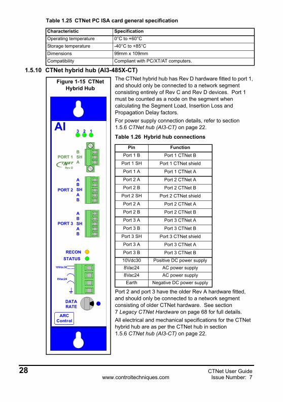
1.5.10 CTNet hybrid hub (AI3-485X-CT)The CTNet hybrid hub has Rev D hardware fitted to port 1, and should only be connected to a network segment consisting entirely of Rev C and Rev D devices. Port 1 must be counted as a node on the segment when calculating the Segment Load, Insertion Loss and Propagation Delay factors.For power supply connection details, refer to section 1.5.6 CTNet hub (AI3-CT) on page 22.
Port 2 and port 3 have the older Rev A hardware fitted, and should only be connected to a network segment consisting of older CTNet hardware. See section 7 Legacy CTNet Hardware on page 68 for full details.All electrical and mechanical specifications for the CTNet hybrid hub are as per the CTNet hub in section 1.5.6 CTNet hub (AI3-CT) on page 22.
Table 1.25 CTNet PC ISA card general specification
Characteristic SpecificationOperating temperature 0°C to +60°CStorage temperature -40°C to +85°CDimensions 99mm x 109mmCompatibility Compliant with PC/XT/AT computers.
Table 1.26 Hybrid hub connections
Pin FunctionPort 1 B Port 1 CTNet B
Port 1 SH Port 1 CTNet shield
Port 1 A Port 1 CTNet A
Port 2 A Port 2 CTNet A
Port 2 B Port 2 CTNet B
Port 2 SH Port 2 CTNet shield
Port 2 A Port 2 CTNet A
Port 2 B Port 2 CTNet B
Port 3 A Port 3 CTNet A
Port 3 B Port 3 CTNet B
Port 3 SH Port 3 CTNet shield
Port 3 A Port 3 CTNet A
Port 3 B Port 3 CTNet B10Vdc30 Positive DC power supply8Vac24 AC power supply8Vac24 AC power supplyEarth Negative DC power supply
RECON
DATARATE
3 2 1
PORT 2
PORT 3 SHB
A
STATUS
10Vdc30
8Vac24
A
B
SHB
A
A
B
AI
ARCControl
SHB
AN
PORT 1
Rev D
Figure 1-15 CTNet Hybrid Hub
28 CTNet User Guidewww.controltechniques.com Issue Number: 7

The cable screen should be connected to the CTNet shield pin, but should also be clamped to earth before it gets to the hub. (See section 1.8 CTNet shield connections on page 31.)
1.5.11 CTNet fibre optic repeater (AI2-CT/FOG-ST)The CTNet fibre optic repeater has Rev D hardware fitted to Port 1, and should only be connected to a network segment consisting entirely of Rev C and Rev D devices. Port 1 must be counted as a node on the segment when calculating the Segment Load, Insertion Loss and Propagation Delay factors.The fibre optic link uses 2 glass optical fibre cables in a duplex arrangement, and paired fiber optic cable is available for this purpose. The TX output from a fibre optic repeater should be connected to the RX input at the other end of the fibre. The fibre optic link is invisible to the higher level protocol operation of the CTNet network. A fibre optic link is particularly useful to prevent earth potential equalisation currents from flowing in the screen of the CTNet cable, e.g. between separate buildings, as it provides full electrical isolation between the electrical segments in each building.
All other electrical and mechanical specifications and connections for the CTNet fibre optic repeater are as per the CTNet Hub in section 1.5.6 CTNet hub (AI3-CT) on page 22. The cable screen should be connected to the CTNet Shield pin, but should also be clamped to earth before it gets to the fibre optic repeater. (See section 1.8 CTNet shield connections on page 31.)
Table 1.27 Fibre optic connections
Pin FunctionPort 1 B Port 1 CTNet B
Port 1 SH Port 1 CTNet shield
Port 1 A Port 1 CTNet APort 2 TX Port 2 Optical Output (850nm wavelength)Port 2 RX Port 2 Optical Input (850nm wavelength only)10Vdc30 Positive DC power supply8Vac24 AC power supply8Vac24 AC power supplyEarth Negative DC power supply
RECON
DATARATE
2 1
STATUS
10Vdc30
8Vac24
TX
RX
PORT 2
AI
ARCControl
SHB
AN
PORT 1
Rev D
Figure 1-16 CTNet fibre optic repeater
CTNet User Guide 29Issue Number: 7 www.controltechniques.com

Paired multimode glass fibre optic cable must be used, and must be terminated with bayonet style ST connectors. Suitable fibre sizes are 50/125, 62.5/125, and 100/140. The optical power budget is shown in Table 1.28.
1.6 CTNet cableCustomised CTNet cable is available from Control Techniques. Cable is an integral part of any transmission line system, and CTNet has been designed and optimised to use this cable. Control Techniques cannot guarantee reliable CTNet operation if any other type of cable is used.
1.7 CTNet segment terminationEvery CTNet network segment must be terminated at each end of the cable with 82Ω resistors. The cable arrangement must be “point-to-point”. “Drop lengths” of unterminated cable are not permitted on a CTNet network. In applications where a
Table 1.28 Optical power budget at 25°C
Fibre size (µm) Max link loss (dB) Max fibre loss (dB/km) Max fibre length (m)50/125 6.6 4.3 915
62.5/125 10.4 4.3 1825100/140 15.9 4.0 2740
Table 1.29 CTNet cable physical characteristics
Characteristic SpecificationNominal weight 5.8 kg per 100m
Nominal diameter 6.2mmMinimum bend radius 65mm
Temperature rating -20°C to +60°CFlame resistance UL 1581 vertical tray
30 CTNet User Guidewww.controltechniques.com Issue Number: 7
piece of portable equipment contains CTNet nodes, all “active” lengths of cable must be correctly terminated. This may mean that “terminator” plugs need to be used in connectors when the equipment is disconnected and moved elsewhere.
Some CTNet devices have internal 82Ω resistors that can be enabled to terminate a segment. However, external resistors are recommended as they provide an easy way to visually determine that each segment is correctly terminated.
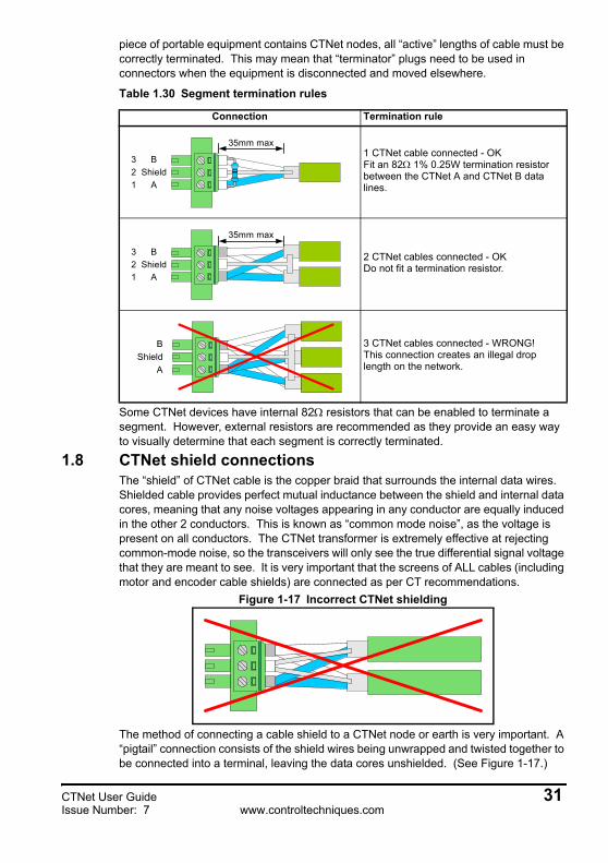
1.8 CTNet shield connectionsThe “shield” of CTNet cable is the copper braid that surrounds the internal data wires. Shielded cable provides perfect mutual inductance between the shield and internal data cores, meaning that any noise voltages appearing in any conductor are equally induced in the other 2 conductors. This is known as “common mode noise”, as the voltage is present on all conductors. The CTNet transformer is extremely effective at rejecting common-mode noise, so the transceivers will only see the true differential signal voltage that they are meant to see. It is very important that the screens of ALL cables (including motor and encoder cable shields) are connected as per CT recommendations.
Figure 1-17 Incorrect CTNet shielding
The method of connecting a cable shield to a CTNet node or earth is very important. A “pigtail” connection consists of the shield wires being unwrapped and twisted together to be connected into a terminal, leaving the data cores unshielded. (See Figure 1-17.)
Table 1.30 Segment termination rules
Connection Termination rule
1 CTNet cable connected - OKFit an 82Ω 1% 0.25W termination resistor between the CTNet A and CTNet B data lines.
2 CTNet cables connected - OKDo not fit a termination resistor.
3 CTNet cables connected - WRONG!This connection creates an illegal drop length on the network.
35mm max
ShieldB
A23
1
ShieldB
A
35mm max
23
1
ShieldB
A
CTNet User Guide 31Issue Number: 7 www.controltechniques.com
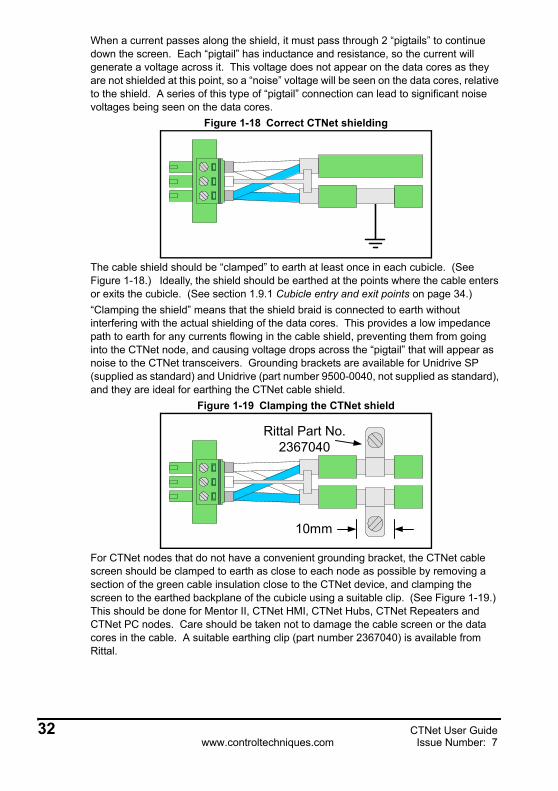
When a current passes along the shield, it must pass through 2 “pigtails” to continue down the screen. Each “pigtail” has inductance and resistance, so the current will generate a voltage across it. This voltage does not appear on the data cores as they are not shielded at this point, so a “noise” voltage will be seen on the data cores, relative to the shield. A series of this type of “pigtail” connection can lead to significant noise voltages being seen on the data cores.
Figure 1-18 Correct CTNet shielding
The cable shield should be “clamped” to earth at least once in each cubicle. (See Figure 1-18.) Ideally, the shield should be earthed at the points where the cable enters or exits the cubicle. (See section 1.9.1 Cubicle entry and exit points on page 34.)“Clamping the shield” means that the shield braid is connected to earth without interfering with the actual shielding of the data cores. This provides a low impedance path to earth for any currents flowing in the cable shield, preventing them from going into the CTNet node, and causing voltage drops across the “pigtail” that will appear as noise to the CTNet transceivers. Grounding brackets are available for Unidrive SP (supplied as standard) and Unidrive (part number 9500-0040, not supplied as standard), and they are ideal for earthing the CTNet cable shield.
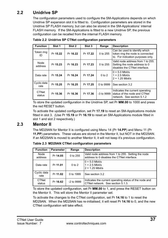
Figure 1-19 Clamping the CTNet shield
For CTNet nodes that do not have a convenient grounding bracket, the CTNet cable screen should be clamped to earth as close to each node as possible by removing a section of the green cable insulation close to the CTNet device, and clamping the screen to the earthed backplane of the cubicle using a suitable clip. (See Figure 1-19.) This should be done for Mentor II, CTNet HMI, CTNet Hubs, CTNet Repeaters and CTNet PC nodes. Care should be taken not to damage the cable screen or the data cores in the cable. A suitable earthing clip (part number 2367040) is available from Rittal.
Rittal Part No.2367040
10mm
32 CTNet User Guidewww.controltechniques.com Issue Number: 7

1.8.1 Breaking earth loopsIf a segment of CTNet network covers a large distance, e.g. more than 100m, and the earth points at each end of the segment are at different potentials, a ground loop may be created when the CTNet cable shield is earthed at each end of the segment. This will allow earth potential equalisation currents to flow in the screen of the CTNet cable.Ground loops can be broken by connecting the cable shield to earth via a Y2 250Vac 1nF capacitor. The capacitor will allow high frequency noise currents to pass straight through, but it will block any low frequency (50 or 60 Hz) currents.
Figure 1-20 Shield connections to break earth loops
1.9 Joining CTNet cables togetherIn many systems, it is necessary to break into a length of CTNet cable for convenient design, installation and use of the overall system. Typical examples are:• CTNet panel entry and exit points. (See section 1.9.1 Cubicle entry and exit
points on page 34.)• Using 2 pieces of CTNet cable to extend a segment length. (See section
1.9.2 Joining 2 pieces of CTNet cable on page 35.)• Connection points for portable pieces of equipment containing CTNet devices.
(See section 1.9.3 Connection points for portable equipment on page 35.)When the screen around data cables is disturbed, the cable begins to lose its inherent noise immunity, and the data wires can start to pick up some noise. Attention to detail and correct screen connections around cable break-in points can keep this noise pick-up to a minimum, and well below any noise levels that may start to cause problems.
The CTNet cable shield must be connected directly to earth at a minimum of one location on each segment.
NOTE
CTNet User Guide 33Issue Number: 7 www.controltechniques.com

1.9.1 Cubicle entry and exit pointsThe screen of each CTNet cable should be earthed to the backplane of the panel at the point where the data cores emerge from the cable. Figure 1-21 shows a standard terminal block arrangement with a suitable earth screen clamping clip (see Figure 1-19) to clamp the screen to the cubicle backplane. (Rittal Part No. 2367060)
Figure 1-21 Cubicle entry/exit connections
Alternatively, screw clamps (Phoenix Contact Part No. 3025163) can be used to clamp the cable to a copper busbar, earthed via the support brackets (Phoenix Contact Part No. 3025341) and the DIN rail. The data cores are linked using standard connection terminals, but the total length of unscreened data path should not exceed 70mm.It is preferable to provide convenient connections for the CTNet cable at the cubicle entry and exit points. This allows the system installer (who may not have any previous experience with wiring a CTNet network) to link up with the CTNet network without disturbing the CTNet layout within the cubicle. Earth screen clips or cable clamps should be supplied with the cubicle, and the person installing the CTNet cable should be made aware of the importance of following the wiring instructions in this User Guide.
CTNet links toother cubicles
Copper busbar,earthed via busbarsupport bracket andDIN rail to the back-plane
Screwclamps
The DIN rail MUSTbe in direct contactwith the unpaintedpanel back-plane toensure a goodelectrical connectionto the back-plane
70mmmax
Unpainted panelbackplane
CTNet link toother devices in
the cubicle
Earthclips
Busbar supportbracket availablefrom Phoenix Contact(Part No. 3025341)
34 CTNet User Guidewww.controltechniques.com Issue Number: 7

1.9.2 Joining 2 pieces of CTNet cableMulti pole connectors are available that offer electro-magnetic interference shielding when locked. These types of connectors are ideal for use in breaking a CTNet cable to pass it thorough a panel wall, or for linking 2 pieces of CTNet cable together at a point where it is necessary to be able to connect and disconnect the network.2 pins are required for the CTNet A and CTNet B connections, with the shell of the connector being used to link the screens of the cables. The shell is usually clamped to the screen of the CTNet cable, thus ensuring that the data cores remain fully screened when the connector is locked.
1.9.3 Connection points for portable equipmentSome applications may have a piece of portable equipment that needs to be moved to different points on the production line for different products. If this piece of machinery contains CTNet devices, it has to be connected to the CTNet network. CTNet is particularly suited to this type of system, but the physical wiring layout of the network must be considered for every possible network arrangement.The best method is to design and install the segments required for the fixed devices, and consider the requirements for the portable equipment as a separate segment, and link it to the rest of the network using a CTNet Hub.The segment must be terminated correctly in all machine configurations, and the segment must meet the specifications described in section 1.3 CTNet segment design on page 7. Lengths of cable that are not actually connected to the segment in a particular machine configuration do not need to be terminated.
1.10 Other wiring tips• Where possible, do not route CTNet cable close to motor cables. Motor cables
carry high frequency currents and an extended close parallel run with CTNet cable will result in some of this his high frequency current being induced in the CTNet cable screen.
• Try to keep the area enclosed by the CTNet cables to a minimum. A large loop coming back to the same starting point will act as an aerial, and the larger the area enclosed by the cable, more noise pick-up will be seen. The enclosed area can be kept to a minimum by running the out and return cables right next to each other. This may not always be possible, particularly if a segment length is getting close to its maximum, but it will keep any electrical pick-up to a minimum.
The network segment will be incorrectly terminated while the cables are disconnected.NOTE
CTNet User Guide 35Issue Number: 7 www.controltechniques.com

2 Getting StartedIf 2 nodes with the same node address are connected to a CTNet network, they will try to transmit at the same time, and will interfere with each other. Similarly, if a node is configured with a different data rate to the rest of the network, it will not recognise valid messages.For these reasons, when configuring a CTNet node, follow the steps listed below BEFORE connecting the node to the CTNet network:1. Configure the node address. Every node on a CTNet network must have a unique
node address.2. Set the node data rate. Every node on a CTNet network must be configured to
operate at the same data rate.3. Store and activate the new configuration.4. Connect the node to the network.
2.1 UnidriveThe UD75-CTNet module for Unidrive is configured using menu 20 (Pr 20.PP) parameters. These values are stored in the FLASH memory of the UD70, so the UD75-CTNet will keep any previous configuration if it is fitted to another Unidrive.
To store and activate the updated configuration, set Pr 17.19 to 1. This will store the Pr 20.PP values to the UD70 FLASH memory, and fully reset the UD70 and CTNet interface.
Table 2.1 UD75-CTNet configuration parameters
Function Parameter Range DescriptionNode
address Pr 20.01 0 to 255 Valid node address from 1 to 255. Setting the node address to 0 disables the CTNet interface.
Data rate Pr 20.02 0 to 20 = 5.0 Mbit/s1 = 2.5 Mbit/s2 = 1.25 Mbit/s
Cyclic data rate Pr 20.03 0 to 25099 See section 3.2
CTNet status Pr 20.50 -2 to 9999 Indicates the current operating status of the node
and CTNet network. See section 5.1.1.
36 CTNet User Guidewww.controltechniques.com Issue Number: 7
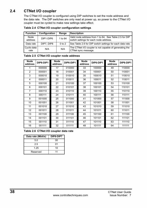
2.2 Unidrive SPThe configuration parameters used to configure the SM-Applications depends on which Unidrive SP expansion slot it is fitted to. Configuration parameters are stored in the Unidrive SP FLASH memory, but can also be stored in the SM-Applications’ internal FLASH memory. If the SM-Applications is fitted to a new Unidrive SP, the previous configuration can be recalled from the internal FLASH memory.
To store the updated configuration in the Unidrive SP, set Pr MM.00 to 1000 and press the red RESET button.To activate the updated configuration, set Pr 17.19 to reset an SM-Applications module fitted in slot 3. (Use Pr 15.19 or Pr 16.19 to reset an SM-Applications module fitted in slot 1 and slot 2 respectively.)
2.3 Mentor IIThe MD29AN for Mentor II is configured using Menu 14 (Pr 14.PP) and Menu 11 (Pr 11.PP) parameters. These values are stored in the Mentor II, but NOT in the MD29AN. If an MD29AN is moved to another Mentor II, it will not keep it’s previous configuration.
To store the updated configuration, set Pr MM.00 to 1, and press the RESET button on the Mentor II. This will store the Mentor II parameter set.To activate the changes to the CTNet configuration, set Pr 14.16 to 1 to reset the MD29AN. When the MD29AN has re-initialised, it will reset Pr 14.16 to 0, and the new CTNet configuration will take effect.
Table 2.2 Unidrive SP CTNet configuration parameters
Function Slot 1 Slot 2 Slot 3 Range Description
Token ring ID Pr 15.22 Pr 16.22 Pr 17.22 0 to 255
Can be used to identify which token ring the node is connected to. For indication purposes only.
Node address Pr 15.23 Pr 16.23 Pr 17.23 0 to 255
Valid node address from 1 to 255. Setting the node address to 0 disables the CTNet interface.
Data rate Pr 15.24 Pr 16.24 Pr 17.24 0 to 20 = 5.0 Mbit/s1 = 2.5 Mbit/s2 = 1.25 Mbit/s
Cyclic data rate Pr 15.25 Pr 16.25 Pr 17.25 0 to 9999 See section 3.2
CTNet status Pr 15.36 Pr 16.36 Pr 17.36 -3 to 9999
Indicates the current operating status of the node and CTNet network. See section 5.1.2
Table 2.3 MD29AN CTNet configuration parameters
Function Parameter Range DescriptionNode
address Pr 14.05 0 to 255 Valid node address from 1 to 255. Setting the node address to 0 disables the CTNet interface.
Data rate Pr 11.01 0 to 20 = 5.0 Mbit/s1 = 2.5 Mbit/s2 = 1.25 Mbit/s
Cyclic data rate Pr 11.02 0 to 1999 See section 3.2
CTNet status Pr 16.62 -2 to 9999 Indicates the current operating status of the node and
CTNet network. See section 5.1.3.
CTNet User Guide 37Issue Number: 7 www.controltechniques.com
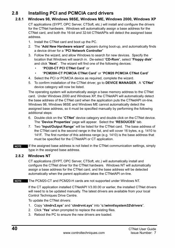
2.4 CTNet I/O couplerThe CTNet I/O coupler is configured using DIP switches to set the node address and the data rate. The DIP switches are only read at power up, so power to the CTNet I/O coupler must be cycled to make new settings take effect.
Table 2.4 CTNet I/O coupler configuration settings
Function Configuration Range DescriptionNode
address DIP1-DIP6 1 to 64 Valid node address from 1 to 64. See Table 2.5 for DIP switch settings for each node address.
Data rate DIP7, DIP8 0 to 2 See Table 2.6 for DIP switch settings for each data rate.Cyclic data
rate N/A N/A The CTNet I/O coupler is not capable of generating the CTNet sync message.
Table 2.5 CTNet I/O coupler node address
Node address DIP6-DIP1 Node
address DIP6-DIP1 Node address DIP6-DIP1 Node
address DIP6-DIP1
1 000000 17 010000 33 100000 49 1100002 000001 18 010001 34 100001 50 1100013 000010 19 010010 35 100010 51 1100104 000011 20 010011 36 100011 52 1100115 000100 21 010100 37 100100 53 1101006 000101 22 010101 38 100101 54 1101017 000110 23 010110 39 100110 55 1101108 000111 24 010111 40 100111 56 1101119 001000 25 011000 41 101000 57 111000
10 001001 26 011001 42 101001 58 11100111 001010 27 011010 43 101010 59 11101012 001011 28 011011 44 101011 60 11101113 001100 29 011100 45 101100 61 11110014 001101 30 011101 46 101101 62 11110115 001110 31 011110 47 101110 63 11111016 001111 32 011111 48 101111 64 111111
Table 2.6 CTNet I/O coupler data rate
Data rate (Mbit/s) DIP8-DIP75.0 002.5 011.25 10
Reserved 11
38 CTNet User Guidewww.controltechniques.com Issue Number: 7

2.5 CTNet HMI (CTIU200)The CTNet HMI is configured using the CTIU configuration package. To configure the CTNet settings:1. Select “Configure”, “Select Terminal Type” and choose “CTIU200”.2. Select “Configure” and “Communication Settings”.3. Set “Remote Equipment Manufacturer” to “Control Techniques”.4. Set “Remote Equipment Model” to “Second proc using CTNet”.5. Select “Network Mode Enable”.6. Specify the CTNet node address (1 to 255) in “HMI Network Node”.The CTNet settings will take effect when the project is downloaded to the CTNet HMI. If “Network Mode Enable” is not selected, the CTNet HMI will only attempt to communicate with the CTNet node address specified in “Global Remote Node ID”.
2.6 CTNet HubThe CTNet Hub does not require a node address, but the correct data rate must be configured using the selector switch. The selector switch is only read at power up, so power to the CTNet Hub must be cycled to make the new setting take effect.
2.7 CTNet PC cardsThe node address and data rate for the CTNet PC cards are both configured by the CTNetAPI when it goes on-line, and can be specified when the CTNetAPI is installed. These settings can be changed from within all Control Techniques applications that support CTNet, e.g. SYPT, CTSoft and OPC Server. Ensure that the correct hardware type is selected when the data rate is specified.
Table 2.7 CTNet Hub data rate configuration
Function Configuration Range Description
Data rate DATA RATE switch 5 to 7
0-4 = reserved5 = 1.25 Mbit/s6 = 2.5 Mbit/s7 = 5.0 Mbit/s
There is a known problem with V1.0.0.0 CTNet driver. If the PC goes into “hibernation” or “sleep” mode, the CTNet card is not powered up when the PC returns to normal operating mode, and a connection error will result when the CTNetAPI attempts to access the card. This problem can be overcome by disabling “Hibernation” and “Sleep” modes, or by going to Device Manager and disabling and re-enabling the CTNet card. With a PCMCIA card, temporarily removing the PCMCIA card will have the same effect.
NOTE
CTNet User Guide 39Issue Number: 7 www.controltechniques.com
2.8 Installing PCI and PCMCIA card drivers2.8.1 Windows 98, Windows 98SE, Windows ME, Windows 2000, Windows XP
CT applications (SYPT, OPC Server, CTSoft, etc.) will install and configure the drivers for the CTNet hardware. Windows will automatically assign a base address for the CTNet card, and both the 16-bit and 32-bit CTNetAPIs will detect the assigned base address.1. Install the CTNet card and boot up the PC.2. The “Add New Hardware wizard” appears during boot-up, and automatically finds
a device driver for a “PCI Network Controller”3. Follow the wizard, and allow Windows to search for new devices. Specify the
location that Windows will search in. De-select “CD-Rom”, select “Floppy disk” and click “Next”. The wizard will find one of the following devices:• “PCI20-CT PCI CTNet Card” or• “PCM20H-CT PCMCIA CTNet Card” or “PCM20 PCMCIA CTNet Card”
4. Select the PCI or PCMCIA device as required, complete the wizard.5. To confirm installation of the CTNet driver, go to DEVICE MANAGER. A “CTNet”
device category will now be listed.The operating system will automatically assign a base memory address to the CTNet card. Under Windows 2000 and Windows XP, the CTNetAPI will automatically detect the base address of the CTNet card when the application puts the CTNetAPI on-line. Windows 98, Windows 98SE and Windows ME cannot automatically detect the assigned base address, so it must be specified manually by performing the following additional steps:6. Double click on the “CTNet” device category and double click on the CTNet device.
The “Device Properties” page will appear. Select the “RESOUCES” tab.7. Two “Input/Output Range” will be listed for the CTNet card. The base address of
the CTNet card is the second range in the list, and will cover 16 bytes, e.g. 1410 to 141F. The first number of this address range (e.g. 1410) is the base address that must be specified for the CTNetAPI or CT application.
2.8.2 Windows NTCT applications (SYPT, OPC Server, CTSoft, etc.) will automatically install and configure the CTNet driver for the CTNet hardware. Windows NT will automatically assign a base address for the CTNet card, and the base address will be detected automatically when the parent application takes the CTNetAPI on-line.
If the CT application installed CTNetAPI V3.00.00 or earlier, the installed CTNet drivers will need to is be updated manually. The latest drivers are available from your local Control Techniques Drive Centre.To update the CTNet drivers:1. Copy “ctndrv2.sys” and “ctndrvnt.sys” into “c:\winnt\system32\drivers”.2. Click “Yes” when prompted to replace the existing files.3. Reboot the PC to ensure the new drivers are loaded.
If the assigned base address is not listed in the CTNet communication settings, simply type in the assigned base address.
NOTE
The PCM20-CT and PCM20-H cards are not supported under Windows NT.NOTE
40 CTNet User Guidewww.controltechniques.com Issue Number: 7

2.8.3 Windows 95Please refer to section 7.4 CTNet drivers for Windows 95 on page 70 for information on using CTNet under Windows 95.
2.9 Installing the PC ISA cardAs the ISA bus is not plug-and-play, Windows cannot automatically assign a base address to the PCX20-CT card. The base address must be configured manually using the jumper links (E1) on the PCX20-CT card, and entered manually when the CTNetAPI or CT application is loaded and configured. Table 2.8 shows the jumper link settings for the required base address.
CTNet does not use an interrupt line, so all interrupts should be disabled on the PCX20-CT card. Ensure that none of the E1 links are fitted.
Table 2.8 PCX20-CT base address configuration
Base address A9 A8 A7 A6 A5 A4 Base
address A9 A8 A7 A6 A5 A4
100 280110 290120 2A0130 2B0140 2C0150 2D0160 2E0170 2F0180 300190 3101A0 3201B0 3301C0 3401D0 3501E0 3601F0 370200 380210 390220 3A0230 3B0240 3C0250 3D0260 3E0270 3F0
- indicates that the jumper link should be fitted
CTNet User Guide 41Issue Number: 7 www.controltechniques.com

3 Cyclic DataWhen a de-centralised control system is used to control a machine or production process, the real-time data about the machine is spread around the nodes on the system. To implement effective control, some of this data must be regularly transferred to other devices to allow the control system to react to changing conditions.CTNet provides the digital communications link to transfer data between distributed intelligent nodes (Unidrive, Unidrive SP and Mentor II) running DPL programs.
3.1 What is cyclic data?“Cyclic data” is the method of automatic real-time data transfer used on CTNet. During system commissioning, a series of “cyclic data links” are configured to move data between nodes as required, allowing other devices to respond accordingly.One node on a CTNet network must be designated as the “sync node”. When this node transmits the “sync message”, this is the signal to all other nodes that it is time to re-transmit the configured cyclic data links, thus ensuring that fast changing data is regularly updated in the other nodes on the network.
Table 3.1 Glossary of terms
Term Definition
cyclic data Method of automatic data transfer between nodes on a CTNet network. Configured during system commissioning.
cyclic data rateThe time period between transmission of the cyclic “sync message”. Defined as SSSFF, where FF = fast cyclic data time (in ms) and SSS = ratio of slow data to fast cyclic data.
sync node The node on the network that coordinates cyclic data transfer by transmitting the “sync message” at regular intervals.
sync message The CTNet sync message is used to instruct all other nodes to starting transmitting their “cyclic data links”.
cyclic linkDefines the data registers to be transmitted from a node, the total number of registers to be transmitted, and the registers in the target node where the data is to be written.
fast link A cyclic link that is transmitted after every sync message
slow link A cyclic link that is transited after every SSSth sync message, as defined by the synchronisation rate
broadcast link A cyclic link that is received by all nodes on the network
Table 3.2 Supported cyclic data features
Node Cyclic data “Easy mode” Sync message capable DPL capable
Unidrive Yes Yes Yes YesUnidrive SP Yes Yes Yes Yes
Mentor II Yes Yes Yes YesCTNet I/O Yes No No NoCTIU200 No No No NoPC cards No No No No
42 CTNet User Guidewww.controltechniques.com Issue Number: 7

3.2 Cyclic data rateCyclic data is coordinated on the CTNet network by the sync node. The “sync rate” is specified as SSSFF, where FF is the time period (in ms) between cyclic data transfers, and SSS is the ratio of slow cyclic transfers to fast cyclic transfers. For example, a setting of 1005 in a Unidrive SP would result in fast cyclic data being transferred every 5ms, and slow cyclic data being transferred every 10 * 5ms, i.e. 50ms.
When Unidrive or Mentor II are configured to generate the sync message, the internal timebase used to generate the sync message is not 1ms. The actual fast data rate generated will be the next highest multiple of the timebase ABOVE the specified fast cyclic time. For example, the fast cyclic rate setting of 1005 at 6kHz switching frequency on a Unidrive will actually produce fast cyclic data every 6.9ms, with slow cyclic data every 69ms.
3.3 Configuring cyclic data linksCyclic data is configured using the Cyclic Data Editor in the SYPT Workbench application, and is incorporated into the DPL program when this is downloaded to the node. Cyclic data links are configured in the source (transmitting) node only, and the following details are specified:1. Source register2. Number of consecutive registers3. Priority (fast or slow)4. Target node5. Destination register in target nodeWhen the sync message is received, data is read from the source register(s) and transmitted to the target register(s) in the target node. If multiple registers are transmitted, data is read from and written to consecutive registers following on from the source and target registers. Up to 20 registers can be transmitted on a single cyclic data link.The total number of data links that can be configured for a source node is 10 links. This includes both fast and slow cyclic data links, although the cyclic links can be in any combination. There is no limit on the number of cyclic links that can be sent to a single
Table 3.3 Cyclic sync message timebase
Node Sync rate Timebase Comment
Unidrive Pr 20.031.38ms Switching frequency is 3, 6 or 12 kHz (Pr 5.17 = 0, 2 or
4)1.84ms Switching frequency is 4.5 or 9 kHz (Pr 5.17 = 1 or 3)
Unidrive SPPr 15.25
1msSM-Applications module fitted in slot 1
Pr 16.25 SM-Applications module fitted in slot 2Pr 17.25 SM-Applications module fitted in slot 3
Mentor II Pr 11.02 2.56ms
If the sync node is powered down or disconnected from the CTNet network for any reason, cyclic data transfer will stop. The AutoSync function block can be used in the DPL program of all sync-capable nodes to ensure that another node will take over responsibility for the sync message, and cyclic data will continue to be transferred. Refer to section 6.1 Automatic sync node assignment on page 65 for more details.
NOTE
CTNet User Guide 43Issue Number: 7 www.controltechniques.com

target node; however, the finite processing power of the target node will limit the number of messages that it can handle. (See section 5.6 Overloading a node on page 63 for more details.)The range of registers that can be used as source and target registers for cyclic data links depends on the source and target node. Table 3.4 shows the range of registers or parameters that can be used as source and target registers for cyclic data links.
Cyclic data links can be edited by the DPL program in a Unidrive, Mentor II or Unidrive SP node. Refer to section 6.2 Editing cyclic data links on page 65 for further details.
3.4 “Easy mode” cyclic dataA non-DPL method of setting up cyclic data transfer using CTNet is to use the “easy mode” set-up. “Easy mode” uses drive parameters to configure data transfer and parameter mapping at each node, and can be configured either from the drive keypad, or via the RS485 port using CTSoft, UniSoft or MentorSoft. Data transfer capabilities are limited, but no DPL code is required.With “easy mode”, each node has IN and OUT data slots, similar in concept to analogue inputs and outputs. IN data is defined as data coming IN to a node, i.e. analogue input, while OUT data is transmitted OUT from the node, i.e. analogue output. Unidrive and Unidrive SP have 3 IN and 3 OUT channels, while the Mentor II has 2 IN and 2 OUT channels.
The OUT data channels are configured by specifying the source parameter within the source node, the target node address, and the IN data channels where the data should be written to in the target node. The IN data channels receive data from other nodes on the network, and they only require mapping information to specify the target parameter for the incoming data. The mapping cannot be changed dynamically, as a full reset must be performed to make any changes take effect. (See section 2 Getting Started on page 36.)
Table 3.4 Cyclic data source and destination registers
Drive Device Source registers
Destination register Comment
Unidrive UD75 _R00% to _R79%
_S00% to _79%
_R80% to _R99% and _S80% to _S99% are reserved on the Unidrive CTNet module.
Unidrive SP SM-Applications
_R00% to _R99%
_S00% to _S99%
Mentor II MD29AN _R00% to _R79%
_S00% to _S79%
_R80% to _R99% and _S80% to _S99% are reserved on Unidrive CTNet module.
CTNet I/O BK7200
Pr 1.00 to Pr 1.15
Pr 2.00 to Pr 2.15 Digital inputs and outputs
Pr 3.00 to Pr 3.99
Pr 4.00 to Pr 4.99 Analogue inputs and outputs
The CTNet I/O Coupler does NOT support “easy mode” cyclic data transfer.NOTE
44 CTNet User Guidewww.controltechniques.com Issue Number: 7

3.4.1 Unidrive“Easy mode” cyclic data is configured using menu 20 parameters on Unidrive. The mapping control parameters are shown in Table 3.5.
The source and destination parameters are entered in the form MMPP, where MM is the menu number and PP is the parameter number. The destination node and channel is entered in the form NNNCC, where NNN is the destination node address, and CC is the IN channel to write to.If any mapping parameter is set to an invalid value (target parameter is read-only or does not exist), the mapping will revert to 0 when a reset occurs. If a slot is not being used, it can be disabled by setting the mapping to 0.
3.4.2 Unidrive SP“Easy mode” cyclic data is configured using channel configuration parameters in the Unidrive SP. The mapping control parameters are shown in Table 3.6.
The source and destination parameters are entered in the form MMPP, where MM is the menu number and PP is the parameter number. The destination node and channel is entered in the form NNNCC, where NNN is the destination node address, and CC is the IN channel to write to.If any mapping parameter is set to an invalid value (target parameter is read-only or does not exist), the mapping will revert to 0 when a reset occurs. If a channel is not being used, it can be disabled by setting the mapping to 0.
Table 3.5 Unidrive “easy mode” configuration
Channel Source/destination parameter
Destination node and channel
IN channel 1 Pr 20.10 (MMPP)IN channel 2 Pr 20.11 (MMPP)IN channel 3 Pr 20.12 (MMPP)
OUT channel 1 Pr 20.05 (MMPP) Pr 20.04 (NNNCC)OUT channel 2 Pr 20.07 (MMPP) Pr 20.06 (NNNCC)OUT channel 3 Pr 20.09 (MMPP) Pr 20.08 (NNNCC)
Table 3.6 Unidrive SP “easy mode” configuration
ChannelSource/destination parameter Destination node and channelSlot 1 Slot 2 Slot 3 Slot 1 Slot 2 Slot 3
IN channel 1 Pr 15.32 Pr 16.32 Pr 17.32IN channel 2 Pr 15.33 Pr 16.33 Pr 17.33IN channel 3 Pr 15.34 Pr 16.34 Pr 17.34
OUT channel 1 Pr 15.27 Pr 16.27 Pr 17.27 Pr 15.26 Pr 16.26 Pr 17.26OUT channel 2 Pr 15.29 Pr 16.29 Pr 17.29 Pr 15.28 Pr 16.28 Pr 17.28OUT channel 3 Pr 15.31 Pr 16.31 Pr 17.31 Pr 15.30 Pr 16.30 Pr 17.30
CTNet User Guide 45Issue Number: 7 www.controltechniques.com
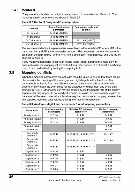
3.4.3 Mentor II“Easy mode” cyclic data is configured using menu 11 parameters on Mentor II. The mapping control parameters are shown in Table 3.7.
The source and destination parameters are entered in the form MMPP, where MM is the menu number and PP is the parameter number. The destination node and channel is entered in the form NNNC, where NNN is the destination node address, and C is the IN channel to write to.If any mapping parameter is set to an invalid value (target parameter is read-only or does not exist), the mapping will revert to 0 the a reset occurs. If a channel is not being used, it can be disabled by setting the mapping to 0.
3.5 Mapping conflictsWhen the mapping parameters are set, care must be taken to ensure that there are no clashes with the mapping of the analogue and digital inputs within the drive. If a parameter is written to from two different sources, the value of this parameter will depend entirely upon the scan times for the analogue or digital input and cyclic data timing of CTNet. Further confusion may be caused due to the update rate of the display. A parameter may appear to be steady at a particular value, but occasionally, a glitch in the value will be seen. Internally, this value may be continuously changing between the two supplied incoming data values, leading to erratic drive behaviour.
Table 3.7 Mentor II “easy mode” configuration
Channel Source/destination parameter
Destination node and channel
IN channel 1 Pr 11.07 (MMPP)IN channel 2 Pr 11.08 (MMPP)
OUT channel 1 Pr 11.04 (MMPP) Pr 11.03 (NNNC)OUT channel 2 Pr 11.06 (MMPP) Pr 11.05 (NNNC)
Table 3.8 Analogue, digital and “easy mode” input mapping parameters
Drive input Unidrive mapping parameters
Unidrive SP mapping parameters
Mentor II mapping parameters
Analogue input 1 Pr 7.10 Pr 7.10 Pr 7.11Analogue input 2 Pr 7.14 Pr 7.14 Pr 7.12Analogue input 3 Pr 7.18 Pr 7.18 Pr 7.13Analogue input 4 Pr 7.14
Speed input Pr 7.15Easy mode channel 1 Pr 20.10 Pr 15.32, Pr 16.32, Pr 17.32 Pr 11.07
Easy mode channel 2 Pr 20.11 Pr 15.33, Pr 16.33, Pr 17.33 Pr 11.08
Easy mode channel 3 Pr 20.12 Pr 15.34, Pr 16.34, Pr 17.34
Digital input 1 Pr 8.10 Pr 8.21Digital input 2 Pr 8.13 Pr 8.22 Pr 8.12Digital input 3 Pr 8.16 Pr 8.23 Pr 8.13Digital input 4 Pr 8.19 Pr 8.24 Pr 8.14Digital input 5 Pr 8.21 Pr 8.25 Pr 8.15Digital input 6 Pr 8.23 Pr 8.26 Pr 8.16
46 CTNet User Guidewww.controltechniques.com Issue Number: 7

Digital input 7 Pr 8.17Digital input 8 Pr 8.18Digital input 9 Pr 8.19
Digital input 10 Pr 8.20Logic output 1 Pr 9.10 Pr 9.10Logic output 2 Pr 9.20 Pr 9.20Motorised pot
outputPr 9.25 Pr 9.25
Comparator 1 output
Pr 12.07 Pr 12.07 Pr 12.07
Comparator 2 output
Pr 12.17 Pr 12.27 Pr 12.17
Variable select 1 output
Pr 12.11
Variable select 2 output
Pr 12.31
PID output Pr 14.16 Pr 14.16
Table 3.8 Analogue, digital and “easy mode” input mapping parameters
Drive input Unidrive mapping parameters
Unidrive SP mapping parameters
Mentor II mapping parameters
CTNet User Guide 47Issue Number: 7 www.controltechniques.com

4 Non-Cyclic DataThe non-cyclic data channel allows a node to access any parameter or virtual parameter in any other network node. This function is particularly useful for transmitting infrequent events around the network.One non-cyclic transaction is serviced by the network controller every 8ms. This limits the number of non-cyclic messages that be handled by a node to 125 per second. The token-ring architecture of CTNet provides the capability for any node to communicate directly with another node on the network. Nodes that are capable of both sending and receiving non-cyclic messages can communicate with each other at any time.DPL-capable nodes are able to issue non-cyclic messages to other nodes and respond to non-cyclic messages issued by another node. Source-only nodes, such as CTIU200 and PC cards, can issue non-cyclic messages, but they will not respond to non-cyclic messages received from other nodes on the network.Target-only nodes, such as CTNet I/O, will respond to non-cyclic messages issued from other nodes, but they cannot issue non-cyclic messages as they cannot run DPL programs.
4.1 Non-cyclic message handlingNon-cyclic messages (requests and responses) are transferred into a FIFO non-cyclic buffer as they are received. The buffer can hold 5 messages, and any subsequent messages received whilst the buffer is full will be lost. The host processor checks the non-cyclic buffer every 8ms, and will process one message if there are messages in the buffer.A “non-cyclic request” is a message initiated by a node to read data from or write data to a location within another node. The SYPT watch window uses non-cyclic messages to read data from or write data to parameters and program variables. DPL programs are also downloaded to a node using non-cyclic data.A “non-cyclic response” is a message generated in response to a “non-cyclic request” message received from another node. This can be a response with the data requested, or simply an acknowledgement that a received instruction was executed successfully.When a non-cyclic request message is issued by the DPL program, it is transferred to the output buffer immediately, and put in the queue for transmission. When the token is next received, provided that there are no cyclic data messages waiting to be transmitted, the message will be sent over the CTNet network.
Table 4.1 Non-cyclic capabilities
Node Initiate non-cyclic messages
Respond to non-cyclic messages
Unidrive Yes YesUnidrive SP Yes Yes
Mentor II Yes YesCTNet I/O coupler No Yes
CTNet HMI Yes NoPC cards Yes No
48 CTNet User Guidewww.controltechniques.com Issue Number: 7

4.2 Non-cyclic message delaysDue to the low priority of non-cyclic messages, the time delay between requesting a parameter from a remote node and receiving a response will depend on the loading of the CTNet network. As the number of nodes increases, the token will be received less often, so the delay between request and response messages being transferred to the output buffer and actual transmission will increase. Similarly, as the network loading due to cyclic data increases, non-cyclic request and response messages may have to wait for several token rotations while higher priority cyclic messages are transmitted.
4.3 Reading parameters over CTNetThe ReadNet function block is provided in SYPT to allow the DPL program to read parameters from other nodes on the CTNet network. ReadNet can be called from any DPL task, and uses minimal resources while waiting for the remote node to respond.Full details and example DPL code are available in the SYPT help file.
4.4 Writing parameters over CTNetThe WriteNet function block is provided in SYPT to allow the DPL program to write data to parameters in other nodes on the CTNet network. WriteNet can be called from any DPL task, and uses minimal resources while waiting for the remote node to respond.Full details and example DPL code are available in the SYPT Help File.
4.5 Check if node existsThe CheckNode function block allows a DPL program to determine whether a target node address is present on the network or not.Full details and example DPL code are available in the SYPT Help File.
CTNet User Guide 49Issue Number: 7

5 Diagnostics5.1 CTNet status indication
5.1.1 UnidriveCTNet status is indicated in Pr 20.50 on Unidrive, and is updated once per second. Table 5.1 shows the CTNet network status on Unidrive.
The CTNet control software is part of the UD70 system file (UD70NET.SYS) and the system file version can be read from Pr 17.02.
5.1.2 Unidrive SPCTNet status is indicated in Pr MM.36 in Unidrive SP, where MM is the menu of parameters associated with the slot in which the SM-Applications module is installed. The status display value is updated once per second. Table 5.2 shows the CTNet network status on Unidrive.
5.1.3 Mentor IICTNet status is indicated in Pr 16.62 in Mentor II, and is updated once per second. Table 5.3 shows the CTNet network status on Mentor II.
Table 5.1 Unidrive CTNet status
Pr 20.50 Indication
-2 Initialisation failure. The UD70 was unable to configure the CTNet interface. Check that the node address and data rate are set correctly.
-1 A network reconfiguration has been detected.
0The low-level token ring has been established and is active, but the node is not receiving any CTNet data messages. Indicates that there are no problems with the physical wiring of the CTNet network.
>0 Indicates the number of CTNet messages being processed every second.
Table 5.2 Unidrive SP CTNet status
Pr MM.36 Indication
-3 Network reconfiguration issued. The SM-Applications module forced a CTNet network reconfiguration.
-2 Initialisation failure. The SM-Applications module was unable to configure the CTNet interface. Check that the node address and data rate are set correctly.
-1 A network reconfiguration has been detected.
0 The low-level token ring has been established and is active, but the node is not receiving any CTNet data messages.
>0 Indicates the number of CTNet messages being processed every second.
Table 5.3 Mentor II CTNet status
Pr 16.62 Indication
-2 Initialisation failure. The MD29AN was unable to configure the CTNet interface. Check that the node address and data rate are set correctly.
-1 A network reconfiguration has been detected during the previous second.
0 The low-level token ring has been established and is active, but the node is not receiving any CTNet data messages.
>0 Indicates the number of CTNet messages being processed every second.
50 CTNet User Guidewww.controltechniques.com Issue Number: 7
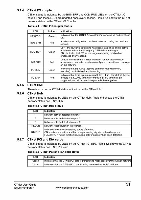
5.1.4 CTNet I/O couplerCTNet status is indicated by the BUS ERR and COM RUN LEDs on the CTNet I/O coupler, and these LEDs are updated once every second. Table 5.4 shows the CTNet network status on the CTNet I/O Coupler.
5.1.5 CTNet HMIThere is no external CTNet status indication on the CTNet HMI.
5.1.6 CTNet HubCTNet status is indicated by LEDs on the CTNet Hub. Table 5.5 shows the CTNet network status on CTNet Hub.
5.1.7 CTNet PCI and ISA cardsCTNet status is indicated by LEDs on the CTNet PCI card. Table 5.6 shows the CTNet network status on CTNet PCI card.
Table 5.4 CTNet I/O coupler status
LED Colour Indication
HEALTHY Green Indicates that the CTNet I/O coupler has powered up and initialised OK.
BUS ERR Red A network reconfiguration has been detected during the previous second.
COM RUN Green
OFF - the low-level token ring has been established and is active, but the node is not receiving any CTNet data messages.ON - indicates that CTNet messages are being received and processed every second.
INIT ERR RedUnable to initialise the CTNet interface. Check that the node address and data rate have been configured correctly and is unique on the network
I/O RUN Green Indicates that the K-bus (used to communicate with the I/O modules) has initialised and is running.
I/O ERR RedIndicates that there is a problem with the K-bus. Check that the last module is a KL9010 terminator module, all I/O terminals are supported, and all modules are properly fitted together.
Table 5.5 CTNet Hub status
LED Indication1 Network activity detected on port 12 Network activity detected on port 23 Network activity detected on port 3
RECON Network reconfiguration in progress
STATUSIndicates the current operating status of the hubON = network is active and hub is regenerating signals to the other portsFLASHING = hub is functioning, but no network activity has been detected
Table 5.6 CTNet PCI and ISA card ctatus
LED IndicationGreen Indicates that the CTNet PCI card is transmitting messages over the CTNet networkYellow Indicates that the CTNet PCI card is being accessed via its I/O address.
CTNet User Guide 51Issue Number: 7 www.controltechniques.com

5.1.8 CTNet PCMCIA cardCTNet status is indicated by LEDs on the CTNet PCI card. Table 5.7 shows the CTNet network status on CTNet PCI card.
5.2 CTNet configuration errorsConfiguration errors are detected as part of the initialisation sequence of the CTNet node. During initialisation, the node effectively monitors the CTNet network, and if any of the tests fail, the node does not go on-line. This prevents an incorrectly configured node from interfering with the operation of the existing network.CTNet configuration errors will cause a drive trip when the CTNet interface is initialised. shows the trip that will be seen on the drive, and the location of the trip code that indicates why the drive was tripped.
5.2.1 Hardware errorThe internal CTNet hardware could not be correctly initialised. Cycle the power to the device to clear the error. If the fault persists, replace the CTNet module and contact Control Techniques.
5.2.2 Invalid configurationThe node address or data rate settings are outside of the permitted range. Valid settings are 0 to 255 for the node address, and 0 to 2 for the data rate.
5.2.3 Data rate mismatchDuring initialisation, the CTNet node will monitor the CTNet network, checking for network activity, and waiting to receive the token from another node. If network activity is detected, but no token is received, the node assumes that the configured data rate is incorrect. The node will continue to attempt to join the token ring by issuing a network reconfiguration once per second. Set the correct data rate and reset the node. When the reset sequence is complete, the node will try again to join the token ring.
Table 5.7 CTNet PCMCIA card status
LED Indication
GreenON - indicates that the PCMCIA card is currently active and on-line and taking part in the token ring.OFF - PCMCIA card is off-line
Table 5.8 CTNet configuration error trip codes
Error Unidrive Mentor II Unidrive SPHardware error
(See section 5.2.1)“tr60”
Pr 10.20 = 60“A29”
Pr 10.35 = 60“SLx.Er“
Pr MM.50 = 60Invalid configuration(See section 5.2.2)
“tr61”Pr 10.20 = 61
“A29”Pr 10.35 = 61
“SLx.Er“Pr MM.50 = 61
Data rate mismatch(See section 5.2.3)
“tr62”Pr 10.20 = 62
“A29”Pr 10.35 = 62
“SLx.Er“Pr MM.50 = 62
Duplicate node address(See section 5.2.4)
“tr63”Pr 10.20 = 63
“A29”Pr 10.35 = 63
“SLx.Er“Pr MM.50 = 63
Illegal cyclic data rate(See section 5.2.5)
“tr64”Pr 10.20 = 64
“A29”Pr 10.35 = 64 Not applicable
The “x” in the Unidrive SP trip display will indicate the slot number that caused the trip. MM should be replaced by the appropriate menu for the slot, i.e. MM = 15 for slot 1, MM = 16 for slot 2, MM = 17 for slot 3.
NOTE
52 CTNet User Guidewww.controltechniques.com Issue Number: 7
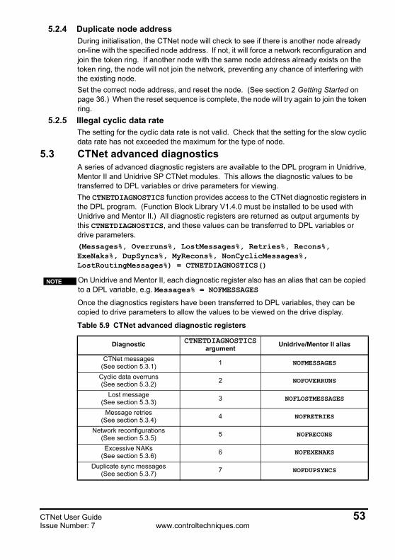
5.2.4 Duplicate node addressDuring initialisation, the CTNet node will check to see if there is another node already on-line with the specified node address. If not, it will force a network reconfiguration and join the token ring. If another node with the same node address already exists on the token ring, the node will not join the network, preventing any chance of interfering with the existing node.Set the correct node address, and reset the node. (See section 2 Getting Started on page 36.) When the reset sequence is complete, the node will try again to join the token ring.
5.2.5 Illegal cyclic data rateThe setting for the cyclic data rate is not valid. Check that the setting for the slow cyclic data rate has not exceeded the maximum for the type of node.
5.3 CTNet advanced diagnosticsA series of advanced diagnostic registers are available to the DPL program in Unidrive, Mentor II and Unidrive SP CTNet modules. This allows the diagnostic values to be transferred to DPL variables or drive parameters for viewing.The CTNETDIAGNOSTICS function provides access to the CTNet diagnostic registers in the DPL program. (Function Block Library V1.4.0 must be installed to be used with Unidrive and Mentor II.) All diagnostic registers are returned as output arguments by this CTNETDIAGNOSTICS, and these values can be transferred to DPL variables or drive parameters.(Messages%, Overruns%, LostMessages%, Retries%, Recons%, ExeNaks%, DupSyncs%, MyRecons%, NonCyclicMessages%, LostRoutingMessages%) = CTNETDIAGNOSTICS()
Once the diagnostics registers have been transferred to DPL variables, they can be copied to drive parameters to allow the values to be viewed on the drive display.
On Unidrive and Mentor II, each diagnostic register also has an alias that can be copied to a DPL variable, e.g. Messages% = NOFMESSAGES
Table 5.9 CTNet advanced diagnostic registers
Diagnostic CTNETDIAGNOSTICS argument Unidrive/Mentor II alias
CTNet messages(See section 5.3.1) 1 NOFMESSAGES
Cyclic data overruns(See section 5.3.2) 2 NOFOVERRUNS
Lost message(See section 5.3.3) 3 NOFLOSTMESSAGES
Message retries(See section 5.3.4) 4 NOFRETRIES
Network reconfigurations(See section 5.3.5) 5 NOFRECONS
Excessive NAKs(See section 5.3.6) 6 NOFEXENAKS
Duplicate sync messages(See section 5.3.7) 7 NOFDUPSYNCS
NOTE
CTNet User Guide 53Issue Number: 7 www.controltechniques.com

During network initialisation, different nodes may be powered up at different times and take longer to go on-line. As the network status is constantly changing during this period, cyclic data overruns, lost messages and/or duplicate sync messages may be registered. However, a CTNet network running under steady conditions with all nodes continuously on-line should not see any change in the number of cyclic data overruns, lost messages or duplicate sync messages.These diagnostic registers indicate the operational status of the high-level CTNet protocol. CTNet protocol errors do not actually prevent the a node from communicating on a network, and do not cause the network to fall over. However, a CTNet network may appear to be operating correctly, but there may circumstances where problems can appear that may not immediately be obvious.
5.3.1 CTNet messages
Messages% is initialised to 0 after reset, and is incremented by 1 for every CTNet message transmitted or received. Each cyclic data message, cyclic sync message, transmitted broadcast non-cyclic write message and received non-cyclic broadcast message will be counted as 1 message. All other non-cyclic messages will be counted as 2 messages, as 1 transmit message and 1 receive message will be seen.Messages% will roll-over from 2147483647 to -2147483647 if the node is not reset. This must be allowed for when using this value in a DPL program.
5.3.2 Cyclic data overruns
If a new fast cyclic sync message is received BEFORE the node has completed the transmission of its fast cyclic data links as triggered by previous fast sync message, this is known as a “cyclic data overrun”. When this occurs, the node will ignore the new cyclic sync message, and finish transmitting the defined fast links. It will then wait for another fast cyclic sync message to arrive before starting to transmit the fast cyclic data links again. The result is that fast cyclic data will only be transmitted on every other fast sync message, so the update rate in the target node is effectively halved. The same applies to slow cyclic data.
My network reconfigurations(See section 5.3.8) 8 NOFMYRECONS
CTNet non-cyclic messages(See section 5.3.9) 9 NOFNONCYCLICMESSAGES
Lost routing messages(See section 5.3.10) 10 Not available. Will always return 0
on Unidrive and Mentor II
Table 5.9 CTNet advanced diagnostic registers
Diagnostic CTNETDIAGNOSTICS argument Unidrive/Mentor II alias
Argument 1 Range 2147483647 to -2147483648Variable Messages% Reset value 0
Argument 2 Range 0 to 65535Variable Overruns% Reset value 0
54 CTNet User Guidewww.controltechniques.com Issue Number: 7

Overruns% counts the number of occasions where a cyclic data overrun occurs. This value should not be seen to increase on a correctly configured CTNet system operating under steady network conditions. If cyclic overruns are occurring:1. Increase the fast and/or slow cyclic data rate2. Convert some fast cyclic data links to slow cyclic data links.
5.3.3 Lost messages
When non-cyclic request and response messages are received from remote nodes, they are transferred to the FIFO non-cyclic message buffer. The buffer is serviced every 8ms on Unidrive, Mentor II and Unidrive SP, and all messages held in the buffer at that time will be processed. The buffer can hold 6 messages.If a new non-cyclic request or response message is received when the non-cyclic buffer is full, the message will be discarded, and LostMessages% will be incremented.Indicates that messages are being received from the CTNet network faster than the node can process them. When the internal software buffer is full, messages will be lost.
5.3.4 Message retries
If a target node does not respond to the FBE message (See excessive NAKs, section 5.3.6) or the PAC (data) message when a non-cyclic message is issued, the transmitting node will attempt to send the message 5 times before abandoning the message. Causes could be that the target node does not exist, or that the message received by the target node was corrupted and the CRC check failed, indicating problems with the network, e.g. noise of bad connections.Retries% will be incremented every time a message transmission fails, so a count of 5 would be expected for every failed non-cyclic message.
If AUTOSYNC is installed in the DPL program, one cyclic data overrun may be detected when a new node with a lower node address than the current sync node joins the network. The new node will take over as the sync node, and may transmit a new sync message before the expected sync period is complete. Nodes that are still transmitting cyclic data will ignore the new sync message, indicate that a cyclic overrun has occurred, and complete their cyclic data transmissions. When the next sync message is received, cyclic data will continue as normal.
NOTE
Argument 3 Range 0 to 65535Variable LostMessages% Reset value 0
Argument 4 Range 0 to 65535Variable Retries% Reset value 0
CTNet User Guide 55Issue Number: 7 www.controltechniques.com

5.3.5 Network reconfigurations
A “network reconfiguration” is the process by which the nodes on CTNet network generate the token ring arbitration system. (See section 5.3.8 My network reconfigurations on page 58.) No CTNet messages will be transmitted while a network reconfiguration is in progress, but data transfer will automatically restart when the process is complete.A network reconfiguration sequence consists of 3 phases:1. Reconfiguration burstWhen a network reconfiguration condition arises in a node, it will transmit the reconfiguration burst onto the network. The idea is to totally corrupt any messages that are present on the network and destroy the token ring. The reconfiguration burst consists of 8 pulses and 1 space, repeated 765 times. This is longer than the longest possible valid message frame, and guarantees that the token ring will be destroyed.2. Timeout phaseWhen the Activity Timeout time (TAC) has elapsed with no network activity detected, each node will start a pre-defined time-out sequence based on it’s node address. The node with the highest address will time out first, and will start transmitting by sending an Invitation To Transmit (ITT or “token”) message to itself.3. Reconfiguration phaseAfter sending a token to itself, the node will transmit a token to the next higher node address, and wait (TTPFAIL) for a response. (When node address 255 is reached, the node will start again at 1.) If no response is detected, the transmitting node will transmit a token to the next highest node address, and so on until a response is seen. The node that responds will now take over and transmit a token to successive higher node addresses until it in turn gets a response, and so on until the token returns to the highest node address.At this point, every node on the network will know the next highest node address to its own address, token-passing will automatically start, and CTNet messages can be transmitted. The reconfiguration time for a network can be calculated using the following equation:
where:TNR = network reconfiguration time.
TRB = reconfiguration burst transmission time.
TAC = network idle time before reconfiguration time-out sequence will begin.
TRTO = reconfiguration timeout delay.
TTPOK = time taken for a successful token pass.
TTPFAIL = time taken for an unsuccessful token pass.
NTotal = total number of nodes on the network.
NMax = highest node address.
Argument 5 Range 0 to 65535Variable Recons% Reset value 0
TNR TRB TAC TRTO 255 NMax–( )×( ) TTPOK NTotal×( ) TTPFAIL 255 NTotal–( )×( )+ + + +=
56 CTNet User Guidewww.controltechniques.com Issue Number: 7

All timings are shown in microseconds in Table 5.10.
Recons% is incremented by 1 every time a network reconfiguration is detected, and the network status parameter will indicate -1 for 1 second.Network reconfigurations are the most common symptom of a network with major wiring or configuration problems, and identifying the cause of the problem requires a careful and methodical approach, as detailed in section 5.4 Solving network reconfiguration problems on page 59. However, network reconfigurations can also be perfectly legitimate events, caused by user code in a CTNet node. See section 5.3.8 My network reconfigurations on page 58 for further details.
5.3.6 Excessive NAKs
When a node wishes to transmit a message (cyclic, non-cyclic request or non-cyclic response) to a remote node, it sends the free buffer enquiry (FBE) message to the remote node. If the remote node has an internal buffer available to receive the message, it will respond with the acknowledge (ACK) message. The transmitting node will transmit the data packet (PAC) message, and if the remote node receives the PAC message successfully, it will respond again with the ACK message. This concludes a successful message transmission, and the transmitting node will pass the token to the next node in the token ring.If the remote node responds with a negative acknowledge (NAK) message (instead of the ACK message) to an FBE message, the transmitting node will abandon attempts to transmit the message, and will pass the token to the next node address on the network. It will attempt to re-send the same message the next time it receives the token.If a NAK message is received after 4 attempts to send the message, the node will abandon attempts to send the message, and will increment the ExeNaks% register.Excessive NAK errors occur when the internal hardware buffers are both full. These buffers are serviced by an interrupt routine, so messages must be arriving faster than the processor can transfer them out of the hardware buffers. This condition will only be seen when a target node is being swamped with broadcast messages, or on a network operating at 5.0 Mbit/s where multiple nodes are transmitting to a single node. To prevent excessive NAK errors:1. Run the network at a slower data rate.2. Re-design data transfer requirements to reduce the load on the target node.If a node is being overloaded with non-cyclic messages on a network running at 2.5Mbit/s or 1.25Mbit/s, lost non-cyclic messages will be recorded as lost messages. (See section 5.3.3 Lost messages on page 55.)
Table 5.10 Network timings
Variable 5.0 Mbit/s 2.5 Mbit/s 1.25 Mbit/sTRB 1377 2754 5508
TAC 41.2 82.4 164.8
TRTO 73 146 292
TTPOK 14.1 28.2 56.4
TTPFAIL 46.6 93.2 186.4
Argument 6 Range 0 to 65535Variable LostMessages% Reset value 0
CTNet User Guide 57Issue Number: 7 www.controltechniques.com

5.3.7 Duplicate sync messages
Cyclic data on a CTNet network should be controlled by a single node on the network. If two or more nodes are configured to generate the sync message, each sync node will detect that another node is generating a sync message, and will increment the DupSyncs% register.Only 1 node should be configured to generate the sync message. If duplicate sync messages are continuously detected, ensure that another node is not configured to generate the cyclic sync message, and that a DPL program in another node is not trying to enabled the sync message using the SETCTNSYNC function block.
5.3.8 My network reconfigurations
Network reconfigurations are a crucial part of CTNet operation, and may occasionally be seen on a perfectly stable network. It is important to ensure that they are not being caused by user DPL code in Unidrive, Mentor II or Unidrive SP, or by user code in a PC application program.There are 3 conditions under which a network reconfiguration will always be seen and can be accounted for.1. New node joining the network at power up.2. PC node going on-line.3. Node re-joining the network after a reset sequence.It is also possible that a network reconfiguration will occur when a node goes off-line. If the node is in possession of the token when it goes off-line, the token ring is interrupted, and a network reconfiguration will occur to re-establish the token ring. If a node goes off-line when it does not have the token, a network reconfiguration will not occur.MyRecons% is incremented when the node forces a network reconfiguration, allowing the source of the network reconfiguration to be identified. See also section 5.3.5 Network reconfigurations on page 56 and section 5.4 Solving network reconfiguration problems on page 59.
5.3.9 CTNet non cyclic messages
NonCyclicMessages% is initialised to 0 after reset, and is incremented by 1 for every CTNet non-cyclic message processed.
Argument 7 Range 0 to 65535Variable DupSyncs% Reset value 0
If AUTOSYNC is installed in the DPL program, one duplicate sync message may be detected when a new node (node A) with a lower node address than the current sync node (node B) joins the network. Node A will take over as the sync node, and node B will detect the new sync message and register a duplicate sync message. By the time node A transmits another sync message, node B will have disabled sync message generation, no more duplicate sync messages will be registered.
NOTE
Argument 8 Range 0 to 65535Variable MyRecons% Reset value 0
Argument 9 Range 0 to 65535Variable NonCyclicMessages% Reset Value 0
58 CTNet User Guidewww.controltechniques.com Issue Number: 7

5.3.10 Lost routing messages (Unidrive SP Only)
The Unidrive SP was unable to route a CT-RTU message from the Unidrive SP RS485 port to the specified network. Either the SM-Applications is not connected to the CTNet network, or the hardware transmit buffers are full.LostRoutingMessages% will be incremented every time a message transmission fails, so a count of 5 would be expected for every failed non-cyclic message.
5.4 Solving network reconfiguration problemsThe symptom generally seen on a CTNet network with problems is that network reconfigurations are taking place, either spuriously or continuously. This is indicated by a value of -1 in the status parameters on Unidrive, Mentor II and Unidrive SP, the red BUS ERR LED on a CTNet I/O Coupler, and the amber RECON LED on a CTNet Hub. The situation can be made more confusing by the fact that correct data transfer may also be taking place, despite the presence of network reconfigurations.Status parameters on Unidrive, Unidrive SP and Mentor II, the BUS ERR LED on CTNet I/O Couplers and RECON LED on CTNet Hubs are only updated once per second. However, a network reconfiguration will take a maximum of 120ms (see section 5.3.5 Network reconfigurations on page 56) even at the slowest data rate, so data transfer may be successful for the remainder of each 1 second interval.If the network reconfigurations cannot be accounted for as “genuine” (see section 5.3.8 My network reconfigurations on page 58) network reconfigurations, check the configuration of each device:1. Ensure that all nodes on the network have a unique node address.2. Ensure that all nodes on the network (including hubs) have been configured to run
at the correct data rate.3. All nodes must be either be reset or have their power cycled to make changes in
configuration will take effect. (PC nodes must be taken off-line, and will adopt the new settings when they next go on-line.)
Any node on a CTNet network can force a network reconfiguration, and every node on the network can detect that a network reconfiguration sequence has occurred. Hence, while the presence of network reconfigurations is easy to detect, this does not actually give any direct indication as to where the problem is occurring on the network.
5.4.1 Physical network testTo identify the segment containing the node that is initiating the network reconfigurations:1. Disconnect all segments from hubs and repeaters. This makes each segment into a
separate network with its own token ring system, and allows the integrity of each segment to be checked.
2. Remove all data from the network by disabling cyclic data and all DPL programs. All PC and CTNet HMI nodes should be taken off-line. In this condition, the status parameters on Unidrive, Mentor II and Unidrive SP should all indicate 0, and the BUS ERR and COM RUN LEDs on the CTNet I/O Coupler should be off.
If network reconfigurations are still occurring on a segment, there is likely to be a problem with the physical wiring on the segment.
Argument 10 Range 0 to 65535Variable LostRoutingMessages% Reset Value 0
CTNet User Guide 59Issue Number: 7 www.controltechniques.com

3. Disconnect every node from the segment and measure the resistance between the A and B lines. The resistance should be approximately 41Ω, although this will be slightly higher for longer cable runs due to cable resistance.
4. If the resistance measured is in the region of 82Ω, this indicates that a termination resistor is missing or faulty, or there is a faulty connection on the segment that is breaking cable continuity. In effect, the node will see an unterminated portion of network, and signal reflections may interfere with and corrupt genuine data signals.
5. If the data lines are open circuit, the segment is effectively unterminated. Check that termination resistors are fitted, fitted correctly, and are the correct value. If necessary, disconnect and measure the termination resistors to ensure that they actually have the resistance value that they are supposed to have.
6. If the resistance measured is less than 40 ohms but not short circuit, this indicates that there is an additional termination resistor fitted somewhere on the segment. Check that internal termination resistors on CTNet Hubs, Repeaters and PC cards are disabled if external resistors are being used, and remove any external resistors if the internal resistors are enabled.
7. Reconnect 2 nodes and check that the segment operates OK.8. Add 1 node at a time until all nodes are re-connected. One network reconfiguration
will be seen as each new node is added to the network.9. If network reconfigurations start to occur when a node is re-connected, this is a
good indication that the newly connected node is causing the problems. Disconnect this node from the network again.
10. Continue re-connecting other nodes to the segment. If no further network reconfigurations occur, the node responsible for the network reconfigurations has been identified.
11. Re-connect all segments to repeaters. Again, if no network reconfigurations occur, the node responsible for the network reconfigurations has been identified.
For a system experiencing intermittent recons, it may be a bad connection in the system that is causing the problem. The highly scientific “waggle” test is a good way to try and find out where the problem may be. Simply move the CTNet cables next to each node in turn, and observe the status of the network. If network reconfigurations occur, check for following faults:12. Bent pins on the CTNet plug on the device itself. This is an indication that the screw
terminals on the CTNet connector have been over-tightened, and the internal contact mechanism has been damaged. Replace the CTNet connector, taking care not to over-tighten the screw terminal.
13. Broken data wires. Repeated plugging and unplugging of the CTNet cable can cause the data wires to break if they do not have adequeate strain relief. Bootlace ferrules should be fitted (see section 1.4 CTNet wiring practices on page 14) to ensure that adequeate mechanical strength is provided. In particular, check for broken wire that may not be obvious, especially in systems where there may be some vibration.
Each node must be wired as specified in section 1.4 CTNet wiring practices on page 14, otherwise disconnecting the nodes will break the cable continuity, and this test will not be valid.
It is recommended NOT to use the internal termination resistor on PCMCIA cards, as the segment will be left unterminated when the PCMCIA card is disconnected.
NOTE
NOTE
60 CTNet User Guidewww.controltechniques.com Issue Number: 7

5.5 Viewing CTNet signals using an oscilloscopeA dual-channel oscilloscope with MATH function can be used to check the signals on a CTNet segment. Connect CH1 to CTNet A and CH2 to CTNet B, with the earth clips of each probe connected to the screen of the CTNet cable. An external termination resistor provides a convenient place to get to the CTNet A and CTNet B lines without disturbing the network wiring. A typical waveform from a CTNet network running at 2.5 Mbit/s is shown in Figure 5-1.
Figure 5-1 CTNet A and CTNet B signals
Each channel will show the signal voltage on each data line, relative to the screen. “Logic 1” is indicated by the presence of a 50%-50% mark-space ratio pulse, “logic 0” is indicated by a bit period of silence. (See Figure 5-2.) Successive pulses are always of opposite polarity.
Figure 5-2 Expanded view of CTNet A and CTNet B signals
It is usual to see some noise on top of the signal pulses, and oscillations of a couple of volts are not uncommon, particularly if the drives are enabled. If the data signals are imprinted onto a 50Hz or 60Hz wave, this indicates that the screen is not properly earthed on the segment. (See section 1.8 CTNet shield connections on page 31.)
CTNet User Guide 61Issue Number: 7 www.controltechniques.com

The MATH function should be configured to display the difference signal, i.e. CH1 - CH2 or CH2 - CH1. This shows the true differential voltage of the CTNet pulses, and is the voltage seen by the CTNet receiver stage. (See Figure 5-3.)
Figure 5-3 CTNet differential signal
There should be no noise on this signal. If the signal is not “clean”, this would indicate that there is a wiring error somewhere on the network. Logic 1 is represented by a single pulse that is high for half of a bit time, with pulses alternating between positive and negative differential voltages. Logic 0 is represented by a space, i.e. no pulse for a whole bit time. (See Figure 5-4.)
Figure 5-4 Expanded view of CTNet differential signal
62 CTNet User Guidewww.controltechniques.com Issue Number: 7

5.6 Overloading a nodeCTNet cyclic data messages are handled in an interrupt routine in Unidrive and Mentor II, and have higher priority than DPL program tasks. Consequently, as more and more CTNet messages arrive, the amount of processor time available to run the DPL program tasks is reduced. Although the scheduling of time-base tasks in Unidrive and Mentor II (SPEED, ENCODER and CLOCK tasks) is not affected, the amount of code that can be executed in each task without causing task overrun errors is reduced.
5.6.1 Continuous overloadContinuous overload occurs when one node is transmitting and receiving a large number of CTNet cyclic data messages. This is particularly common is a system where a CTNet node has been assigned to act as a central point of control for the system, and all other nodes transmit cyclic data to this central node. As the number of processed messages (both transmitted and received) increases, the processor resources available for is reduced. If resources get too low, operations such as the Position Controller may have to be switched to a slower timebase, resulting is a significant drop in system response times and overall performance.Slowing down the rate of cyclic data transfer and re-structuring the cyclic data links will help to reduce the CTNet load on a node. A sensible value should be chosen for fast cyclic data, as there is little point in transmitting a data value every 2 ms if it is only being updated every 10ms in the source node.Unidrive and Mentor II nodes are capable of processing 4 messages every millisecond, without a serious effect on available processor resources.
5.6.2 Peak overloadPeak overload is usually indicated by a Task Overrun error when there is plenty of processor resource available. It occurs when a node receives a burst of message in quick succession, and the messages arrive quicker than the node can process them.When the CTNet sync message is transmitted, all nodes with cyclic data links configured will start to transmit their cyclic data when they next receive the token, resulting in the target node receiving a burst of data messages after every sync message. As the cyclic messages are processed, the DPL tasks are blocked, and if blocked for long enough, a DPL Task Overrun error can occur.Slowing down the fast cyclic data rate has little effect on peak overload problems, as it simply means that the burst of messages comes less often. This may mean that a DPL Task Overrun error occurs every 2 days instead of every day, but the fact remains that spurious trips may interrupt the operation of a machine. Resetting the node will allow the system to re-start and maybe continue for another 2 days before occurring again, and the customer is unlikely to find this situation acceptable.It is the network data rate that has the biggest effect on peak overload problems, as this affects the time taken to actually transmit a message. Peak overload is most likely to be seen in networks operating at 5.0Mbit/s, as CTNet messages can arrive faster than the node can process them. Broadcast messages also increase the possibility of peak overload problems, as they take less time to transmit than non-broadcast message.
The priority of CTNet message handling can be changed in the SM-Applications module to give higher priority to the POS0 and POS1 tasks. This will prevent task overrun errors when a node receives a large number of CTNet messages in a short time period. (See section 6.6 CTNet priority level on SM-Applications on page 67.)
NOTE
CTNet User Guide 63Issue Number: 7 www.controltechniques.com

A good example where overloading a node with messages can occur is when one node is assigned to monitor the network. All other nodes will continuously increment an internal counter, and use cyclic data to transmit the counter value to the “monitoring” node, to indicate that they are still operating on the network. On a large network, say 50 drives, this can mean that the monitoring node suddenly receives 50 messages in very quick succession, and is unable to process them quickly enough. The effect of the lost messages could indicate to the monitoring node that several drives are not functioning, when this is not actually the case, and all nodes are operating OK.The correct way to implement a network monitoring node is to use the CHECKNODE() command in the BACKGROUND task, and use the monitoring node to interrogate each node in turn, and get the operational status of each node. Alternatively, use ReadNet to read a parameter from each node.
64 CTNet User Guidewww.controltechniques.com Issue Number: 7

6 Advanced Features6.1 Automatic sync node assignment
If the sync node is configured as described in section 3.2, cyclic data will be transferred while the sync node is powered up and on-line. However, if the sync node goes off-line for any reason, cyclic data will stop.In systems where redundancy is required, the transmission of cyclic data must continue to be transmitted if any node (including the sync node) goes off line at any time, or does not join the network when the system is powered up. In either case, it is necessary for the active sync-capable nodes on the network detect that cyclic data is not being transferred, and for another sync-capable node to take over responsibility for generating the sync message.The AUTOSYNC function block is provided in the Function Block Library in SYPT for exactly this purpose. Including AUTOSYNC in the DPL programs of all sync-capable nodes will guarantee that cyclic data will start at system power-up, and will continue to be transferred provided there is at least one sync-capable node active on the CTNet network._R79%, _S79% and 1 fast cyclic data link must be reserved for use with AUTOSYNC, and the Sync Rate configuration parameter (see section 3.2 Cyclic data rate on page 43) must be set to 0. Full details about using AUTOSYNC in a DPL program and example DPL code are available in the SYPT Help Files.
6.2 Editing cyclic data linksExisting cyclic data links can be modified on-the-fly from within the DPL program using the EDITFASTLINK and EDITSLOWLINK commands. Theses commands allow each cyclic data link one at a time. This feature is particularly useful in applications where:1. Redundancy (using AUTOSYNC) is required so that the system will continue to
operate if one or more nodes are missing from the network.2. A production line where different grades or types of finished material require
different sections of the production line to communicate with each other.The command works by completely redefining the set-up for the data link within the fast or slow cyclic data structure.
Full details and example DPL code for using EDITFASTLINK and EDITSLOWLINK are available in the SYPT Manual and SYPT Help Files.
6.3 Enabling and disabling cyclic data linksWhile cyclic data links cannot be created from within the DPL program, it possible to enable and disable a cyclic link, provided that is has already been defined in the node. This is done using the EDITFASTLINK and EDITSLOWLINK commands, with the Regs% argument set to 0 to disable the cyclic link. (See section 6.2 Editing cyclic data links on page 65.) The cyclic link can be re-enabled by calling EDITFASTLINK or EDITSLOWLINK again, with the Regs% argument set from 1 to 20. (AUTOSYNC uses this feature to enable and disable the cyclic link reserved for its use.)
CTNet User Guide 65Issue Number: 7 www.controltechniques.com

Enabling and disabling cyclic data links can be particularly useful in a system where redundancy is required. Each node must have all the necessary links configured to allow it to operate in all required modes in the system, but cyclic links that are not used in a particular operating mode can be disabled to prevent them from being transmitted. This ensures more efficient utilisation of the available CTNet bandwidth.
6.4 EVENT task trigger on UD70The EVENT task is a high priority task in the UD70 that can be triggered either by the following methods:1. Roll-over of the internal timer/counter unit.2. 0-1 transition of digital input 0.3. Sync message from the CTNet network.The EVENT task will run once every time the sync message is received from the CTNet network, but it will NOT be triggered if the node is generating the sync message.
Care must be taken not to put too much code in the EVENT task. It has a higher priority than all other UD70 tasks except the INITIAL task, so an extended EVENT task could easily prevent the SPEED task from running, and cause a run-time trip on the UD70.
It is not possible to edit the cyclic data link configuration in a CTNet I/O Module from the DPL program in another node on the CTNet network.
NOTE
Table 6.1 EVENT task trigger sources
Pr 17.23 EVENT task trigger source Description
0 Timer/counter unitThe EVENT task is triggered when the counter rolls over or under, or by digital input 0 on the UD70. Refer to UD70 Uuer Guide for more information.
1 Cyclic sync message The EVENT task is triggered when the sync message is received form the CTNet network
This feature is only available with system file V2.07.06 and later.NOTE
66 CTNet User Guidewww.controltechniques.com Issue Number: 7

6.5 EVENT task trigger on SM-ApplicationsThe SM-Applications has 4 separate EVENT tasks, and each task can be triggered by one of the following methods:1. Execution of the SCHEDULEEVENT function block in the DPL program.2. Sync message from the CTNet network.The EVENT task will run once every time the sync message is received from the CTNet network. Unlike UD70, the specified EVENT task will be triggered if the node is generating the sync message.
Care must be taken not to put too much code in an EVENT task. They have higher priority all other SM-Applications tasks except the INITIAL task, so an extended EVENT task could easily prevent the POS0 task from running and cause a run-time trip, especially if the POS0 task is running on a very fast timebase.
6.6 CTNet priority level on SM-ApplicationsThe priority of CTNet message handling can be changed to have a lower priority than the POS0 and POS1 tasks. This feature guarantees that the POS0 and POS1 tasks will continue to be executed, even if a large number of CTNet messages are arriving into the SM-Applications.
This feature will prevent the DPL task overrun error (trip 54) that could occur with Unidrive and Mentor II, where CTNet messages have a higher priority than DPL tasks. If a high number of CTNet messages arrived in short period of time, the DPL task would be blocked while the CTNet message are processed, leading to a DPL task overrun error.
Table 6.2 EVENT task trigger sources
Pr MM.35 Task Description0 Disabled No task will be triggered when the sync message is received
1 EVENT The EVENT task will be triggered when the sync message is received or transmitted
2 EVENT1 The EVENT1 task will be triggered when the sync message is received or transmitted
3 EVENT2 The EVENT2 task will be triggered when the sync message is received or transmitted
4 EVENT3 The EVENT3 task will be triggered when the sync message is received or transmitted
Table 6.3 CTNet message priority
Pr MM.44 CTNet message priority Description
0 High priority CTNet messages have higher prioity than the POS0 and POS1 tasks, as per UD75-CTNet and MD29AN modules.
1 Low priority CTNet messages have lower prioity than the POS0 and POS1 tasks
CTNet User Guide 67Issue Number: 7 www.controltechniques.com

7 Legacy CTNet HardwareThe electrical characteristics can be determined by checking the revision level of the CTNet hardware. This table below indicates which hardware level is fitted. All nodes on a segment MUST be Rev C or Rev D to use the Segment Loss Factor and Insertion Loss Factor equations and graphs. If a device with older hardware is connected, refer to section 7.1 for segment limitations regarding number of nodes and length of cable.
7.1 Basic segment limitationsIf a network segment has any older CTNet hardware design connected, the Segment Load, Insertion Loss and Propagation Delay factors cannot be applied to the network segment. Refer to Table 7.1 for a list of older types of hardware, and how to identify them. The number of nodes that can be connected to a single network segment is limited by the drive capability of the weakest node on the network.
The worst case segment configuration must be considered when designing the CTNet network. For example, a network of 10 * Unidrive (Rev B) and 5 * CTNet I/O (Rev B) nodes can be configured without problem, as the total number of nodes is 15.However, if a PC card (Rev A) is subsequently connected to configure the network, the PC hardware is now the weakest node on the segment, so the segment is limited to 6 nodes. The symptom is likely to be continuous or spurious network reconfigurations, as
Table 7.1 Legacy CTNet hardware
Device Reference code Indicated revision Hardware identification
Unidrive UD75None UD75A Issue 1 fittedNone UD75A Issue 3 fitted
Mentor II MD29ANNone MD29AN Issue 1 and Issue 2 are Rev ARev B MD29AN Issue 3 with 5-way connector
CTNet I/O BK7200None
Revision level is printed on the plastic coverRev B
CTNet HMI CTIU200 None Part numbers SSP-2050-0900 or 4500-0007Repeater AI2-485X None Supplied in blue metal case with 5-way CTNet
connectorsHub AI3-485X NonePCI card PCI20/5-485X None RJ45 connectors and DIP switches fitted
PCMCIA
PCM20 with MAU20-485X None Plastic MAU with PCM20 card
PCM20H with MAU20H-485X None Metal MAU with Contemporary Controls labels
and PCM20H cardISA card PCX20-485X None RJ45 connectors and DIP switches fitted
Table 7.2 Basic segment limitations
Device hardware Maximum nodes
Maximum cable length (m)2.5 Mbit/s 5.0 Mbit/s
Rev A (PC card only) 6 100 50Rev A 11 100 50Rev B 15 150 75
The 1.25 Mbit/s or lower data rate must not be used with legacy CTNet hardware.NOTE
68 CTNet User Guidewww.controltechniques.com Issue Number: 7
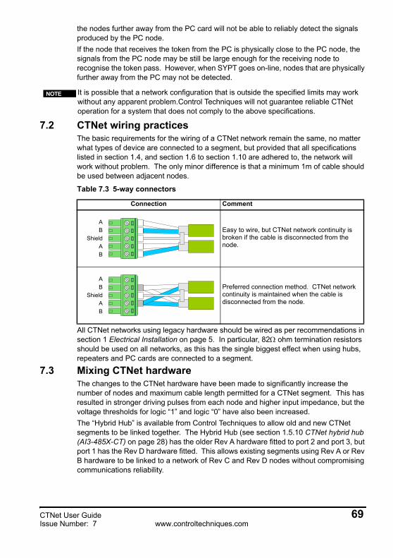
the nodes further away from the PC card will not be able to reliably detect the signals produced by the PC node.If the node that receives the token from the PC is physically close to the PC node, the signals from the PC node may be still be large enough for the receiving node to recognise the token pass. However, when SYPT goes on-line, nodes that are physically further away from the PC may not be detected.
7.2 CTNet wiring practicesThe basic requirements for the wiring of a CTNet network remain the same, no matter what types of device are connected to a segment, but provided that all specifications listed in section 1.4, and section 1.6 to section 1.10 are adhered to, the network will work without problem. The only minor difference is that a minimum 1m of cable should be used between adjacent nodes.
All CTNet networks using legacy hardware should be wired as per recommendations in section 1 Electrical Installation on page 5. In particular, 82Ω ohm termination resistors should be used on all networks, as this has the single biggest effect when using hubs, repeaters and PC cards are connected to a segment.
7.3 Mixing CTNet hardwareThe changes to the CTNet hardware have been made to significantly increase the number of nodes and maximum cable length permitted for a CTNet segment. This has resulted in stronger driving pulses from each node and higher input impedance, but the voltage thresholds for logic “1” and logic “0” have also been increased.The “Hybrid Hub” is available from Control Techniques to allow old and new CTNet segments to be linked together. The Hybrid Hub (see section 1.5.10 CTNet hybrid hub (AI3-485X-CT) on page 28) has the older Rev A hardware fitted to port 2 and port 3, but port 1 has the Rev D hardware fitted. This allows existing segments using Rev A or Rev B hardware to be linked to a network of Rev C and Rev D nodes without compromising communications reliability.
It is possible that a network configuration that is outside the specified limits may work without any apparent problem.Control Techniques will not guarantee reliable CTNet operation for a system that does not comply to the above specifications.
NOTE
Table 7.3 5-way connectors
Connection Comment
Easy to wire, but CTNet network continuity is broken if the cable is disconnected from the node.
Preferred connection method. CTNet network continuity is maintained when the cable is disconnected from the node.
AShield
B
AB
AShield
B
AB
CTNet User Guide 69Issue Number: 7 www.controltechniques.com

7.4 CTNet drivers for Windows 95The Control Techniques CTNet drivers cannot be used under Windows 95. The Contemporary Controls drivers must be used instead. CT applications do NOT automatically install the drivers for CTNet hardware. The procedure listed below should be followed to ensure that the correct drivers are installed. Please refer to your local drive centre for more information on drivers for Windows 95.1. Install the CTNet card and boot up the PC.2. If the “Add New Hardware wizard” appears during boot-up, and asks for a device
driver for a “PCI Network Controller” or “Contemporary Control Systems, Inc.-pcm20 Arcnet Adapter”, go to step 11.
3. Click START, select SETTINGS and click CONTROL PANEL.4. Double click on SYSTEM and select the DEVICE MANAGER tab.5. If a “PCI20” or “PCM20” device category is listed, the correct device driver is already
installed. Go to step 10.6. Click REFRESH. The wizard will detect a “PCI Network Controller” or
“Contemporary Control Systems, Inc.-pcm20 Arcnet Adapter”.7. Follow the wizard, and allow Windows to search for new devices. Select “Display a
list of all the drives in a specific location” and click NEXT to continue.8. Specify the location of the file “PCM20.INF” for a PCI card, and “PCM20.INF” for a
PCMCIA card. The wizard will find one of the following devices:• “Contemporary Controls PCI20/5-485X”• “PCM20”
9. Select the listed device, complete the wizard, and return to the DEVICE MANAGER. A “PCI” or “PCM” device category will now be listed, depending on the type of card installed. The CTNet driver is now installed.
10. Windows 95 will automatically assign a base memory address to the CTNet card. This base address must specified for the CTNetAPI or CT application to allow it to access CTNet via the installed CTNet card To determine the assigned base address, double click on the “PCI” or “PCM” device category and double click on the CTNet device. The DEVICE PROPERTIES page will appear. Select the “RESOURCES” tab.
11. Two “Input/Output Range” will be listed for the CTNet card. The base address of the CTNet card is the second range in the list, and will cover 16 bytes, e.g. 1410 to 141F. The first number of this address range (e.g. 1410) is the base address that must be specified for the CTNetAPI or CT application.
70 CTNet User Guidewww.controltechniques.com Issue Number: 7