beckhoff ctnet i/o - issue 2 - controltech.com.tr ctnet i_o user gu… · beckhoff ctnet i/o 7...
TRANSCRIPT

User Guide
Remote I/O for CTNet
Part Number: 0485-0019-03Issue: 3
www.controltechniques.com
Beckhoff CTNet I/O

General InformationThe manufacturer accepts no liability for any consequences resulting from inappropriate, negligent or incorrect installation or adjustment of the optional operating parameters of the equipment or from mismatching the variable speed drive with the motor.
The contents of this guide are believed to be correct at the time of printing. In the interests of a commitment to a policy of continuous development and improvement, Control Techniques reserves the right to change the specification of the product or it’s performance or the contents of this guide without notice.
All rights reserved. No parts of this guide may be reproduced or transmitted in any form or by any means, electrical or mechanical including photocopying, recording or by an information storage or retrieval system, without permission in writing from the publisher.
Copyright © 22 August 2007 Control Techniques.
Issue Code: 3

Contents1 Safety Information ..........................................................51.1 Warnings, cautions and notes .................................................................51.2 Electrical safety - general warning ..........................................................51.3 System design and safety of personnel ..................................................51.4 Compliance with regulations ...................................................................61.5 Adjusting parameters ..............................................................................6
2 Introduction ....................................................................72.1 Remote I/O for CTNet .............................................................................72.2 BK7200 bus coupler ................................................................................72.3 BK7200 bus coupler features ..................................................................82.4 Hardware description ..............................................................................82.5 BK7200 product specifications ................................................................9
3 Electrical Installation ...................................................103.1 BK7200 main power supply requirements .............................................103.2 Power supply to the power connections ................................................103.3 CTNet connection ..................................................................................113.4 Configuration interface ..........................................................................113.5 K-bus contacts .......................................................................................113.6 Supply isolation .....................................................................................11
4 CTNet Installation .........................................................124.1 BK7200 bus coupler ..............................................................................124.2 CTNet cable ..........................................................................................124.3 Cable specification ................................................................................134.4 Cable screen .........................................................................................134.5 Network termination ..............................................................................134.6 Network limitations ................................................................................14
5 Getting Started .............................................................155.1 Network node address ..........................................................................155.2 Network data rate ..................................................................................165.3 DIP switch example ...............................................................................165.4 Synchronisation message .....................................................................175.5 Network initialisation ..............................................................................175.6 Network loss ..........................................................................................175.7 Network interruptions ............................................................................175.8 Beckhoff coupler programming cable ....................................................17
6 Terminal Configuration ................................................186.1 BK7200 bus coupler ..............................................................................186.2 Digital input terminals ............................................................................196.3 Digital output terminals ..........................................................................226.4 Analogue input terminals .......................................................................246.5 Analogue output terminals .....................................................................266.6 Special function input terminals .............................................................276.7 Special function output terminals ..........................................................276.8 Large terminals ......................................................................................286.9 Example configuration 1 ........................................................................296.10 Example configuration 2 ........................................................................30
Beckhoff CTNet I/O 3Issue Number: 3 www.controltechniques.com

7 Cyclic Data ....................................................................327.1 Fast and slow cyclic data channels .......................................................327.2 Cyclic/Non-cyclic data - time allocations ...............................................327.3 Overloading network nodes ...................................................................337.4 Asynchronous sampling ........................................................................347.5 Setting up the BK7200 for cyclic communications ................................35
8 Non-cyclic Data ............................................................409 Diagnostics ...................................................................419.1 Beckhoff BK7200 bus coupler firmware version ....................................419.2 Diagnostic LEDs ....................................................................................429.3 Error codes and their meanings ............................................................429.4 Location of error ....................................................................................449.5 Cannot establish CTNet connection ......................................................44
10 KS2000 Configuration Tool .........................................4510.1 KS2000 introduction ..............................................................................4510.2 KS2000 features ....................................................................................4510.3 Purchasing KS2000 ...............................................................................47
11 Menu 0 ...........................................................................4811.1 Menu 0 parameters ...............................................................................4811.2 Watchdog ..............................................................................................5111.3 Unsupported terminal ............................................................................5211.4 2-byte PLC interface ..............................................................................53
12 Glossary Of Terms .......................................................54
Index ..............................................................................56
4 Beckhoff CTNet I/Owww.controltechniques.com Issue Number: 3

Safety Inform
ationIntroduction
Electrical Installation
CTN
et Installation
Getting
StartedTerm
inal C
onfigurationC
yclic Data
Non-cyclic D
ataD
iagnosticsKS2000
Configuration Tool
Menu 0
Glossary O
f Term
sIndex
1 Safety Information
1.1 Warnings, cautions and notes
1.2 Electrical safety - general warningThe voltages used in the drive can cause severe electrical shock and/or burns, and could be lethal. Extreme care is necessary at all times when working with or adjacent to the drive.
Specific warnings are given at the relevant places in this User Guide.
1.3 System design and safety of personnelThe BK7200 is intended as a component for professional incorporation into complete equipment or a system. If installed incorrectly, the BK7200 may present a safety hazard.
Drives use high voltages and currents, carry a high level of stored electrical energy, and are used to control equipment which can cause injury.
Close attention is required to the electrical installation and the system design to avoid hazards, either in normal operation or in the event of equipment malfunction. System design, installation, commissioning and maintenance must be carried out by personnel who have the necessary training and experience. They must read this safety information and this User Guide carefully.
The STOP and SECURE DISABLE functions of the drive do not isolate dangerous voltages from the output of the drive or from any external option unit. The supply must be disconnected by an approved electrical isolation device before gaining access to the electrical connections.
With the sole exception of the SECURE DISABLE function, none of the drive functions must be used to ensure safety of personnel, i.e. they must not be used for safety-related functions.
The SECURE DISABLE function is only available as standard on the Unidrive SP.
Careful consideration must be given to the functions of the drive which might result in a hazard, either through their intended behaviour or through incorrect operation due to a fault. In any application where a malfunction of the drive or its control system could lead to or allow damage, loss or injury, a risk analysis must be carried out, and where necessary, further measures taken to reduce the risk - for example, an over-speed protection device in case of failure of the speed control, or a fail-safe mechanical brake in case of loss of motor braking.
A Warning contains information, which is essential for avoiding a safety hazard.
A Caution contains information, which is necessary for avoiding a risk of damage to the product or other equipment.
WARNING
CAUTION
A Note contains information, which helps to ensure correct operation of the product.NOTE
Beckhoff CTNet I/O 5Issue Number: 3 www.controltechniques.com

The SECURE DISABLE function and secure input on Unidrive SP meet the requirements of EN954-1 category 3 for the prevention of unexpected starting of the drive. They may be used in a safety-related application. The system designer is responsible for ensuring that the complete system is safe and designed correctly according to the relevant safety standards.
1.4 Compliance with regulationsThe installer is responsible for complying with all relevant regulations, such as national wiring regulations, accident prevention regulations and electromagnetic compatibility (EMC) regulations. Particular attention must be given to the cross-sectional areas of conductors, the selection of fuses or other protection, and protective earth (ground) connections.
Within the European Union, all machinery in which this product is used must comply with the following directives:
98/37/EC: Safety of machinery.
89/336/EEC: Electromagnetic Compatibility.
1.5 Adjusting parametersSome parameters have a profound effect on the operation of the system. They must not be altered without careful consideration of the impact on the controlled system. Measures must be taken to prevent unwanted changes due to error or tampering.
Consideration must be given to the potential of communications loss and the safe state of outputs.
NOTE
6 Beckhoff CTNet I/Owww.controltechniques.com Issue Number: 3

Safety Inform
ationIntroduction
Electrical Installation
CTN
et Installation
Getting
StartedTerm
inal C
onfigurationC
yclic Data
Non-cyclic D
ataD
iagnosticsKS2000
Configuration Tool
Menu 0
Glossary O
f Term
sIndex
2 Introduction
2.1 Remote I/O for CTNetThe BK7200 provides an interface that allows the Beckhoff modular I/O system to be connected to CTNet networks. The interface is called a “bus coupler” and allows combinations of input and output terminals to be connected to it. It mounts directly onto standard DIN railing.
The BK7200 CTNet Bus Coupler module is the interface between CTNet and the Beckhoff serial K-bus and acts as a buffer for information transfer between the two bus systems. A range of digital and analogue I/O terminals are supported by the CTNet Bus Coupler (see Chapter 6 Terminal Configuration on page 18 for more information).
2.2 BK7200 bus couplerThe most important piece of hardware required to create an I/O point on CTNet is the BK7200 CTNet bus coupler. This module connects directly to the CTNet network and appears on the network as another node. The data rate is selectable from 5.0 Mbits/sec down to 625 Kbits/sec and is configured (along with the node address) using the DIP switches. The BK7200 supports both fast and slow cyclic data and non-cyclic data commands. Although the BK7200 can respond to non-cyclic read and write commands issued by other nodes on the network, it cannot initiate non-cyclic commands (as it does not support DPL). SyPT Lite or SyPT Pro is required to configure cyclic data links within the BK7200 module.
Terminals are addressed using the same menu and parameter structure (#MM.PP) as Control Techiques drives. Each terminal is assigned to a menu according to the type of terminal it is, with the parameter number determined by the physical position of the terminal with respect to other similar terminals. This allows additional terminals to be connected at a later date without affecting the existing terminal configuration.
Digital inputs and outputs are addressed in blocks of 16 bits. This provides an efficient method of transferring digital input and output information around the system without taking up large amounts of the available network bandwidth.
This manual was created in conjunction with BK7200 firmware version 01.04.00, this version contains many more features than any previous versions and is built for use on CTNet Revision D BK7200 devices only. For the use of CTNet Revision A/B BK7200 devices please refer to the Beckhoff CTNet I/O User guide, Issue 1.
24V
+
-
PE
0V
+
-
PEBECK
HOFF
Ν
BK7200
0 1
1
8
HEALTHY
BUS ERR
COM RUN
INIT ERR
I/O RUN
I/O ERR
NOTE
Beckhoff CTNet I/O 7Issue Number: 3 www.controltechniques.com

2.3 BK7200 bus coupler features• Up to 64 bus terminals• Decentralised I/O• Power input terminals for separately powered groups
2.4 Hardware descriptionFigure 2.1 shows an example BK7200 bus coupler configuration and its respective hardware features:
Figure 2-1 The principle of the bus terminal
• CTNet bus coupler BK7200This is the Beckhoff bus coupler which allows you to connect from the Beckhoff I/O terminals onto a CTNet network.
• Power supply for the bus couplerThese two contacts provide the +24V and 0V power supply contacts which provide power to the BK7200 bus coupler.
• Terminal busThis is essentially what connects the terminals together to form a means of data transmission from terminal to terminal (internal and not visible).
• Power input terminalSome analogue input terminals provide the option of inserting an external power supply (this is useful when some terminals on the K-bus require either a higher or lower amount of power than is currently provided along the power contacts).
Possible power isolationPower supply for I/O
KL9010 Busend terminalPart number:
KL9010
Power inputterminalTerminal busPower supply for
the bus couplerCTNet BK7200
bus couplerPart number: BK7200
- -
8 Beckhoff CTNet I/Owww.controltechniques.com Issue Number: 3
Safety Inform
ationIntroduction
Electrical Installation
CTN
et Installation
Getting
StartedTerm
inal C
onfigurationC
yclic Data
Non-cyclic D
ataD
iagnosticsKS2000
Configuration Tool
Menu 0
Glossary O
f Term
sIndex
• Bus end terminalThe last terminal of the terminal bus must be a bus end terminal to terminate the data flow, an example bus end terminal is a KL9010.
• Power supply for I/OThese 3 contacts are the ‘+’, ‘-’ and the ‘Potential Earth’ and provide the power and earthing to the terminals connected to the bus coupler.
• Possible power isolationOn the left-hand side of most of the Beckhoff I/O terminals are two metal contacts. These contacts interlock with the preceding terminals power contacts which provides the terminal with power. Some terminals do not have these 2 contacts, these terminals allow the option of providing an additional power supply to them.
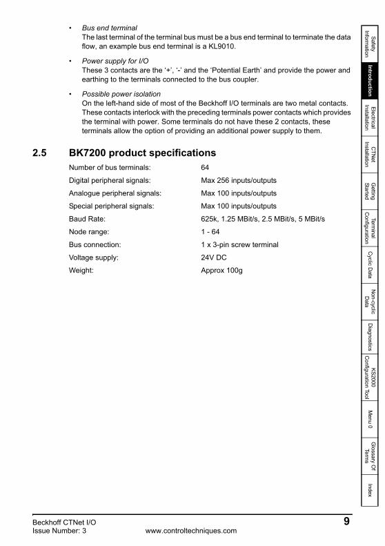
2.5 BK7200 product specificationsNumber of bus terminals: 64
Digital peripheral signals: Max 256 inputs/outputs
Analogue peripheral signals: Max 100 inputs/outputs
Special peripheral signals: Max 100 inputs/outputs
Baud Rate: 625k, 1.25 MBit/s, 2.5 MBit/s, 5 MBit/s
Node range: 1 - 64
Bus connection: 1 x 3-pin screw terminal
Voltage supply: 24V DC
Weight: Approx 100g
Beckhoff CTNet I/O 9Issue Number: 3 www.controltechniques.com

24V
+
-
PE
0V
+
-
PEBECK
HOFF
Ν
BK7200
0 1
1
8
HEALTHY
BUS ERR
COM RUN
INIT ERR
I/O RUN
I/O ERR
24V
+
-
PE
0V
+
-
PEBECK
HOFF
Ν
BK7200
0 1
1
8
HEALTHY
BUS ERR
COM RUN
INIT ERR
I/O RUN
I/O ERR
3 Electrical Installation3.1 BK7200 main power supply requirements
The BK7200 requires a regulated +24V DC power supply, which is connected via the topmost spring terminals, labelled “24V” and “0V”. This supplies the main bus coupler and the serial K-bus. The power supply of the bus coupler circuitry and that of the K-bus are electrically isolated from CTNet.
0V 24V
Nominal Supply Current: 50mA at 24VThe nominal supply current defines the amount of current required only for the BK7200 bus coupler itself. This does not include any power supply requirements for terminal modules via the K-bus.
The current consumption from the K-bus is specified in the Beckhoff data sheets for each terminal module. Once the required configuration of terminals is known, the total current requirements for the bus coupler and K-bus can be calculated.
3.2 Power supply to the power connectionsThe six lower connections with spring terminals is used to supply power to the peripherals. The spring terminals are connected in pairs to the power contacts. The power supply to the power contacts has no connection to the power supply of the bus coupler.
The power contacts are rated for a maximum continuous load of 10A with a +24V DC power supply. This can be connected directly to the supply for the bus coupler itself, provided the power supply can handle the current requirement for all terminal blocks.
+24V
0V
PE (Potential Earth)
The power supply requirements for the power contacts depends entirely on the load current drawn from the power contact by each output.
It is recommended that two separate supplies are used to prevent excessive I/O noise reaching the bus coupler power supply terminals.
NOTE
10 Beckhoff CTNet I/Owww.controltechniques.com Issue Number: 3

Safety Inform
ationIntroduction
Electrical Installation
CTN
et Installation
Getting
StartedTerm
inal C
onfigurationC
yclic Data
Non-cyclic D
ataD
iagnosticsKS2000
Configuration Tool
Menu 0
Glossary O
f Term
sIndex
3.3 CTNet connectionOn the left hand side of the BK7200 bus coupler there is a flat recessed area from which you can plug in a 3-way CTNet connector, this is used to connect the device to a CTNet network (see section 2.1 Remote I/O for CTNet on page 7).
3.4 Configuration interfaceOn the lower left hand side of the BK7200s front face there is a 4-way connector slot underneath a rectangular flap. This is an RS232 interface which allows for the connection of the coupler directly to a PC, this can be used to update the firmware, configure the terminal with KS2000, etc. You could also access the functionality of the configuration interface via the fieldbus by means of the 2-byte PLC interface communications function.
3.5 K-bus contactsAll connections between the bus coupler and the bus terminals are made via gold contacts located on the right hand side of the bus coupler. When the Beckhoff terminals are slotted into each other, these gold contacts create a connection to the connected bus terminals. The K-bus is the component which is responsible for the power supply to the electronic components in the bus terminals and also the data exchanges occuring between the bus terminals, part of this exchange occurs within a ring structure of the K-bus. If a terminal is disconnected from the K-bus the circuit will be broken and no data can be exchanged.
3.6 Supply isolationThe bus coupler operates with three internal independant supplies. The input power supply provides power to the electrically isolated K-bus control circuits in the bus coupler and also the K-bus itself. The power supply is also used to generate the operating voltages for CTNet. All bus terminals are electrically isolated from the K-bus, so that the K-bus is fully isolated electrically.
Beckhoff CTNet I/O 11Issue Number: 3 www.controltechniques.com

4 CTNet Installation
4.1 BK7200 bus coupler
Figure 4-1 Beckhoff BK7200 bus coupler
The BK7200 CTNet coupler (as shown in Figure 4-1 Beckhoff BK7200 bus coupler ) has a single CTNet connector, with the pin out connections as shown in Figure 4-1 Beckhoff BK7200 bus coupler and should be connected as shown in Figure 4-3 CTNet network connections on page 13.
4.2 CTNet cable
Figure 4-2 CTNet cable pinouts
Table 4.1 CTNet cable pinouts (Revision D)
Function CTNet pins DescriptionA 1 Positive data line
Shield 2 Cable screenB 3 Negative data line
24V
+
-
PE
0V
+
-
PEBECK
HOFF
Ν
BK7200
0 1
1
8
HEALTHY
BUS ERR
COM RUN
INIT ERR
I/O RUN
I/O ERR
ShieldB
A
35mm max
23
1
12 Beckhoff CTNet I/Owww.controltechniques.com Issue Number: 3

Safety Inform
ationIntroduction
Electrical Installation
CTN
et Installation
Getting
StartedTerm
inal C
onfigurationC
yclic Data
Non-cyclic D
ataD
iagnosticsKS2000
Configuration Tool
Menu 0
Glossary O
f Term
sIndex
Figure 4-3 CTNet network connections
4.3 Cable specificationFor maximum noise immunity, special CTNet cable must be used.
Table 4.2 CTNet cable part numbers shows the part numbers for the relevant CTNet cable which is available from your local Control Techniques Drive Centre, it is strongly recommended that this cable is used in all CTNet installations.
4.4 Cable screenThe screen of the cable at every node on the network MUST be connected to the screen terminal (pin 2) on the CTNet terminal block (see Figure 4-3 CTNet network connections ). When the screen is stripped back to connect the twisted pair to the CTNet terminals, keep the exposed section of the cable as short as possible.
4.5 Network terminationThe network MUST be fitted with terminating resistors at the end of each segment. If resistors are not fitted, the network may appear to work OK, but the noise immunity of the network will be drastically reduced. The terminating resistor value should match the nominal characteristic impedance value for the cable; in the case of the customised CTNet cable, the terminating resistors used should be 82Ω ±1% 0.25W.
Table 4.2 CTNet cable part numbers
Part Number Description4500-0098 100m CTNet cable4500-0099 200m CTNet cable
Support will not be provided when non-approved CTNet cable is used.NOTE
CTNet shieldCTNet+CTNet-
Beckhoff CTNet I/O 13Issue Number: 3 www.controltechniques.com

4.6 Network limitationsThe BK7200 CTNet bus coupler is capable of driving a maximum of 20 nodes over a maximum network cable length of 44m at 5.0 Mbits/sec. If the network data rate is reduced to 2.5 Mbits/sec, the maximum network length is increased to 100m, but the limit of 20 nodes remains the same.
Table 4.3 CTNet segment specifications
Data rate (Mbit/s) Total cable length (m)5 nodes 10 nodes 15 nodes 20 nodes
5.0 140 100 75 442.5 250 200 150 100
1.25 340 275 200 135
For more information regarding CTNet segment specifications please refer to the CTNet user guide.
Cable grounding: The CTNet cable should be bonded to a suitable grounding point (such as the drive grounding bracket at least once per cabinet).
This manual was created in conjunction with BK7200 firmware version 01.04.00, this version contains many more features than any previous versions and is built for use on CTNet Revision D BK7200 devices only. For the use of CTNet Revision A/B BK7200 devices please refer to the Beckhoff CTNet I/O User guide, Issue 1.
NOTE
NOTE
NOTE
14 Beckhoff CTNet I/Owww.controltechniques.com Issue Number: 3

Safety Inform
ationIntroduction
Electrical Installation
CTN
et Installation
Getting
StartedTerm
inal C
onfigurationC
yclic Data
Non-cyclic D
ataD
iagnosticsKS2000
Configuration Tool
Menu 0
Glossary O
f Term
sIndex
5 Getting Started
5.1 Network node addressThe DIP switches on the BK7200 are used to specify the node address and the data rate. These should be set-up as required before the module is powered up.
Each node on the network must have a unique node address assigned. This is set-up using DIP switches 1 to 6 on the BK7200. The range of addresses for the bus coupler is limited from 1 to 64 (as shown in Table 5.1 Node address look-up table ).
Table 5.1 Node address look-up table
NodeAddress
DIP Switch Node Address
DIP Switch Node Address
DIP Switch6 5 4 3 2 1 6 5 4 3 2 1 6 5 4 3 2 1
1 0 0 0 0 0 0 23 0 1 0 1 1 0 45 1 0 1 1 0 02 0 0 0 0 0 1 24 0 1 0 1 1 1 46 1 0 1 1 0 13 0 0 0 0 1 0 25 0 1 1 0 0 0 47 1 0 1 1 1 04 0 0 0 0 1 1 26 0 1 1 0 0 1 48 1 0 1 1 1 15 0 0 0 1 0 0 27 0 1 1 0 1 0 49 1 1 0 0 0 06 0 0 0 1 0 1 28 0 1 1 0 1 1 50 1 1 0 0 0 17 0 0 0 1 1 0 29 0 1 1 1 0 0 51 1 1 0 0 1 08 0 0 0 1 1 1 30 0 1 1 1 0 1 52 1 1 0 0 1 19 0 0 1 0 0 0 31 0 1 1 1 1 0 53 1 1 0 1 0 0
10 0 0 1 0 0 1 32 0 1 1 1 1 1 54 1 1 0 1 0 111 0 0 1 0 1 0 33 1 0 0 0 0 0 55 1 1 0 1 1 012 0 0 1 0 1 1 34 1 0 0 0 0 1 56 1 1 0 1 1 113 0 0 1 1 0 0 35 1 0 0 0 1 0 57 1 1 1 0 0 014 0 0 1 1 0 1 36 1 0 0 0 1 1 58 1 1 1 0 0 115 0 0 1 1 1 0 37 1 0 0 1 0 0 59 1 1 1 0 1 016 0 0 1 1 1 1 38 1 0 0 1 0 1 60 1 1 1 0 1 117 0 1 0 0 0 0 39 1 0 0 1 1 0 61 1 1 1 1 0 018 0 1 0 0 0 1 40 1 0 0 1 1 1 62 1 1 1 1 0 119 0 1 0 0 1 0 41 1 0 1 0 0 0 63 1 1 1 1 1 020 0 1 0 0 1 1 42 1 0 1 0 0 1 64 1 1 1 1 1 121 0 1 0 1 0 0 43 1 0 1 0 1 022 0 1 0 1 0 1 44 1 0 1 0 1 1
Beckhoff CTNet I/O 15Issue Number: 3 www.controltechniques.com
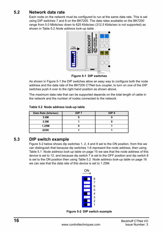
5.2 Network data rateEach node on the network must be configured to run at the same data rate. This is set using DIP switches 7 and 8 on the BK7200. The data rates available on the BK7200 range from 5.0 Mbits/sec down to 625 Kbits/sec (312.5 Kbits/sec is not supported) as shown in Table 5.2 Node address look-up table .
Figure 5-1 DIP switches
As shown in Figure 5-1 the DIP switches allow an easy way to configure both the node address and the data rate of the BK7200 CTNet bus coupler, to turn on one of the DIP switches push it over to the right hand position as shown above.
The maximum data rate that can be supported depends on the total length of cable in the network and the number of nodes connected to the network.
5.3 DIP switch exampleFigure 5-2 below shows dip switches 1, 2, 4 and 8 set to the ON position, from this we can distinguish that because dip switches 1-6 represent the node address, then using Table 5.1 Node address look-up table on page 15 we see that the node address of this device is set to 12, and because dip switch 7 is set to the OFF position and dip switch 8 is set to the ON position then using Table 5.2 Node address look-up table on page 16 we can see that the data rate of this device is set to 1.25M.
Figure 5-2 DIP switch example
Table 5.2 Node address look-up table
Data Rate (bits/sec) DIP 7 DIP 85.0M 0 02.5M 1 01.25M 0 1625K 1 1
87654321
ON
16 Beckhoff CTNet I/Owww.controltechniques.com Issue Number: 3

Safety Inform
ationIntroduction
Electrical Installation
CTN
et Installation
Getting
StartedTerm
inal C
onfigurationC
yclic Data
Non-cyclic D
ataD
iagnosticsKS2000
Configuration Tool
Menu 0
Glossary O
f Term
sIndex
5.4 Synchronisation messageThe cyclic data synchronisation message cannot be generated by the BK7200. To use cyclic data, this message MUST be generated by another node on the network.
5.5 Network initialisationThere are several rules that must be satisfied for the network to initialise correctly.• All nodes must have a unique node address.• All nodes must have the same data rate setting.• Only one node must be set to generate the synchronisation message.
5.6 Network lossIf the CTNet network connection to a BK7200 node is lost for any reason, this will be indicated by the NET ERR light coming on. The module will automatically re-join the network when the network is re-connected to the bus coupler.
5.7 Network interruptionsIf power is lost to a BK7200 node, this does not prevent the network from continuing (apart from the missing node), or being re-started without the “dead” node (other nodes may re-configure to ignore the “dead” node).
5.8 Beckhoff coupler programming cableThe 4-wire RS232 cable required to program a Beckhoff bus coupler via the KS2000 application is available directly from Beckhoff Automated Systems (http://www.beckhoff.com the part number is ‘KS2000-cable’).
There is also a Watchdog function available, see Chapter 11.2 Watchdog on page 51 for more details.
NOTE
Beckhoff CTNet I/O 17Issue Number: 3 www.controltechniques.com

6 Terminal ConfigurationAs the terminal blocks are connected together, each terminal is connected onto the serial K-bus. The BK7200 bus coupler scans the K-bus during initialisation, starting with the terminal block nearest to the bus coupler and checks the ID code. This is repeated for each subsequent terminal connected to the bus. A “database” is built up within the internal memory, which contains a complete image of the status of the input and output terminals. The database acts as a buffer between CTNet and the K-bus, with both systems allowed to read and write data to and from the database.
The database is structured as a two dimensional array, in a similar way to the internal parameter sets of the Unidrive SP. Menu and parameter references are used to address each location within the database.
Each terminal is assigned to a particular pre-defined menu, depending on which type of terminal it is. This means that digital inputs are all grouped together under one menu, the same applies for digital outputs, analogue inputs, analogue outputs, etc.
The parameter reference for each terminal is assigned on a sequential basis. As each new terminal is found, it is assigned the next unused parameter location in the appropriate menu. This process continues to build the database, until all terminals have been assigned to the database (see Table 6.1 Terminal parameter allocations , Chapter 6.9 Example configuration 1 on page 29 and Chapter 6.10 Example configuration 2 on page 30 for example configurations).
6.1 BK7200 bus couplerCombinations of modules may be connected to the BK7200 module, subject to certain limitations:
1. The maximum limit of 64 terminal blocks is not exceeded.2. No more than 256 digital input channels are connected to a single CTNet bus
coupler.3. No more than 256 digital output channels are connected to a single CTNet bus
coupler.4. No more than 100 analogue input channels are connected to a single CTNet bus
coupler.5. No more than 100 analogue output channels are connected to a single CTNet bus
coupler.6. No more than 100 special function input channels are connected to a single CTNet
bus coupler.7. No more than 100 special function output channels are connected to a single CTNet
bus coupler.
18 Beckhoff CTNet I/Owww.controltechniques.com Issue Number: 3

Safety Inform
ationIntroduction
Electrical Installation
CTN
et Installation
Getting
StartedTerm
inal C
onfigurationC
yclic Data
Non-cyclic D
ataD
iagnosticsKS2000
Configuration Tool
Menu 0
Glossary O
f Term
sIndex
Table 6.1 Terminal parameter allocations
6.2 Digital input terminalsDigital inputs are assigned to parameters in menu 1. A maximum of 256 digital inputs can be connected to a single bus coupler (see Table 6.2 Digital input parameter allocations ). All digital input parameters are read-only. Terminals cannot be addressed individually, but each group of 16 inputs can be read using both cyclic and non-cyclic data commands.
Each parameter contains the data from 16 digital input terminals. CTNet actually transfers data as 32-bit double-words, but the upper 16 bits are not used when reading digital inputs. If there are insufficient terminals to utilise all the bits in a parameter, the other bits will be set to 0.
Table 6.2 Digital input parameter allocations
Menu Description Colour Code#1.00 - #1.15 Simple Digital Input Yellow#2.00 - #2.15 Simple Digital Output Red#3.00 - #3.99 Analogue Input Green#4.00 - #4.99 Analogue Output Blue#5.00 - #5.99 Special Function Input Clear#6.00 - #6.99 Special Function Output Clear
b31 b30 b29 b28 b27 b26 b25 b24 b23 b22 b21 b20 b19 b18 b17 b16
b15 b14 b13 b12 b11 b10 b09 b08 b07 b06 b05 b04 b03 b02 b01 b00T15 T14 T13 T12 T11 T10 T09 T08 T07 T06 T05 T04 T03 T02 T01 T00
Reference I/O Points Reference I/O Points#1.00 T0 - T15 #1.08 T128 - T143#1.01 T16 - T31 #1.09 T144 - T159#1.02 T32 - T47 #1.10 T160 - T175#1.03 T48 - T63 #1.11 T176 - T191#1.04 T64 - T79 #1.12 T192 - T207#1.05 T80 - T95 #1.13 T208 - T223#1.06 T96 - T111 #1.14 T224 - T239#1.07 T112 - T127 #1.15 T240 - T255
Beckhoff CTNet I/O 19Issue Number: 3 www.controltechniques.com

6.2.1 Supported terminalsThe bus terminal blocks listed in Table 6.3 Supported digital input terminals below are all classed as “Digital Input Terminals” and are all assigned to parameters in menu 1.
Table 6.3 Supported digital input terminals
For the latest list of supported digital input terminals contact your supplier or local Drive Centre.
NOTE
Type Inputs Outputs DescriptionKL1002 2 n/a 2 digital inputs 24v DC, filter 3.0 ms, 4-wire system.KL1012 2 n/a 2 digital inputs 24v DC, filter 0.2 ms, 4-wire system.KL1032 2 n/a 2 digital inputs 48v DC, filter 3.0 ms, 4-wire system.KL1052 2 n/a 2 digital inputs 24v DC, filter 3.0 ms with p/n switching, 4-wire system.KL1104 4 n/a 4 digital inputs, 24v DC, filter 3.0 ms, 3-wire system.KL1114 4 n/a 4 digital inputs 24v DC, filter 0.2 ms, 3-wire system.KL1124 4 n/a 4 digital inputs 5v DC, filter 0.2 ms, 3-wire system.KL1154 4 n/a 4 digital inputs 24v DC, filter 3.0 ms with p/n switching. 3-wire system.KL1164 4 n/a 4 digital inputs 24v DC, filter 0.2 ms with p/n switching, 3-wire system.KL1184 4 n/a 4 digital inputs 24v DC, filter 3.0 ms with n switching, 3-wire system.KL1194 4 n/a 4 digital inputs 24v DC, filter 0.2 ms with n switching, 3-wire system.KL1212 2 2 2 digital inputs 24v DC, filter 3.0 ms, 3-wire system, short circuit
protected sensor supply.KL1232 2 n/a 2 Digital Inputs 24V DC, Filter 0.2 ms, 2/3/4-wire system, edge
triggered plus expansion.KL1302 2 n/a 2 Digital Inputs 24V DC, Filter 3.0 ms, 2-wire system, for type 2
sensors.KL1304 4 n/a 4 Digital Inputs 24V DC, Filter 3.0 ms, 2-wire system, for type 2
sensors.KL1312 2 n/a 2 Digital Inputs 24V DC, Filter 0.2 ms, 2-wire system, for type 2
sensors.KL1314 4 n/a 4 Digital Inputs 24V DC, Filter 0.2 ms, 2-wire system, for type 2
sensors.KL1352 2 n/a 2 Digital Inputs 24V DC, Filter 3.0 ms, 2-wire system, for NAMUR
sensors.KL1362 2 n/a 2 Digital Inputs 24V DC, Filter 3.0 ms, 2-wire system, for break-in
alarm.KL1382 2 n/a 2 Digital Inputs 24V DC, Filter 30.0 ms, 2-wire system, thermistor.KL1404 4 n/a 4 Digital Inputs 24V DC, Filter 3.0 ms, 4 2-wire system.KL1408 8 n/a 8 Digital Inputs 24V DC, Filter 3.0 ms with P switching, 2-wire system. KL1414 4 n/a 4 Digital Inputs 24V DC, Filter 0.2 ms, 4 2-wire system.KL1418 8 n/a 8 Digital Inputs 24V DC, Filter 0.2 ms with P switching, 2-wire system.KL1434 4 n/a 4 Digital Inputs 24V DC, Filter 0.2 ms, 4 2-wire system, type 2.KL1488 8 n/a 8 Digital Inputs 24V DC, Filter 3.0 ms with N switching, 2-wire system.KL1498 8 n/a 8 Digital Inputs 24V DC, Filter 0.2 ms with N switching, 2-wire system.KL1702 2 n/a 2 Digital Inputs 120V/230V AC, 4-wire system.KL1712 2 n/a 2 Digital Inputs 120V AC/DC, 4-wire system.KL1722 2 n/a 2 Digital Inputs 120V/230V AC, 4-wire system, no power contacts.KM1002 16 n/a 16 Digital Inputs 24V DC, Filter 3.0 ms, 1/2/3-pin system variants.KM1004 32 n/a 32 Digital Inputs 24V DC, Filter 3.0 ms, 1/2/3-pin system variants.KM1008 64 n/a 64 Digital Inputs 24V DC, Filter 3.0 ms, 1/2/3-pin system variants.
20 Beckhoff CTNet I/Owww.controltechniques.com Issue Number: 3

Safety Inform
ationIntroduction
Electrical Installation
CTN
et Installation
Getting
StartedTerm
inal C
onfigurationC
yclic Data
Non-cyclic D
ataD
iagnosticsKS2000
Configuration Tool
Menu 0
Glossary O
f Term
sIndex
KM1012 16 n/a 16 Digital Inputs 24V DC, Filter 0.2 ms, 1/2/3-pin system variants.KM1014 32 n/a 32 Digital Inputs 24V DC, Filter 0.2 ms, 1/2/3-pin system variants.KM1018 64 n/a 64 Digital Inputs 24V DC, Filter 0.2 ms, 1/2/3-pin system variants.
Type Inputs Outputs Description
Beckhoff CTNet I/O 21Issue Number: 3 www.controltechniques.com

6.3 Digital output terminalsDigital outputs are assigned to parameters in menu 2. All digital output parameters are read/write. A maximum of 256 digital outputs can be connected to a single bus coupler (see Table 6.5 Digital output parameter allocations ). Terminals cannot be addressed individually, but each group of 16 outputs can be written to or read from using both cyclic and non-cyclic data commands.
Digital outputs are controlled in groups of 16 bits, with the upper 16 bits of the 32-bit double-words acting as “mask bits”. Mask bits determine whether the corresponding data bit is actually written into the database. This allows addressing of the same block of digital outputs and only update certain outputs. If a mask is set to 1, the corresponding data bit will be updated in the database. If a mask bit is set to 0, the corresponding data bit is not updated in the database.
6.3.1 Mask bits example
A bit mask extracts the status of certain bits in a binary string. For example if we have the binary string 01111010 and it is required to extract the status of the second and sixth bits counting along from the right hand side, a bit mask such as 00100010 would be needed along with the use of the bitwise ‘AND’ operator, recalling that 1 AND 1 = 1, with 0 otherwise, we would find the status of the second and sixth bits, however if the mask value of bit 2 changed back to 0 the value of output bit 2 would stay at 1, to change the value of the second output bit back to 0, mask bit 2 would need to be set to 1 and output bit 2 would need to be set to 0. The functions of this bit mask are shown in Table 6.4 below.
Table 6.4 Mask bit functions
This could be used in practice if only the values of particular bits are required.
Table 6.5 Digital output parameter allocations
b31 b30 b29 b28 b27 b26 b25 b24 b23 b22 b21 b20 b19 b18 b17 b16M15 M14 M13 M12 M11 M10 M09 M08 M07 M06 M05 M04 M03 M02 M01 M00
b15 b14 b13 b12 b11 b10 b09 b08 b07 b06 b05 b04 b03 b02 b01 b00T15 T14 T13 T12 T11 T10 T09 T08 T07 T06 T05 T04 T03 T02 T01 T00
Mask Value Data Value Output0 0 No change from last value (0 or 1)0 1 No change from last value (0 or 1)1 0 01 1 1
Reference I/O Points Reference I/O Points#2.00 T0 - T15 #2.08 T128 - T143#2.01 T16 - T31 #2.09 T144 - T159#2.02 T32 - T47 #2.10 T160 - T175#2.03 T48 - T63 #2.11 T176 - T191#2.04 T64 - T79 #2.12 T192 - T207#2.05 T80 - T95 #2.13 T208 - T223#2.06 T96 - T111 #2.14 T224 - T239#2.07 T112 - T127 #2.15 T240 - T255
22 Beckhoff CTNet I/Owww.controltechniques.com Issue Number: 3

Safety Inform
ationIntroduction
Electrical Installation
CTN
et Installation
Getting
StartedTerm
inal C
onfigurationC
yclic Data
Non-cyclic D
ataD
iagnosticsKS2000
Configuration Tool
Menu 0
Glossary O
f Term
sIndex
6.3.2 Supported terminalsThe bus terminal blocks listed in Table 6.6 Supported digital output terminals below are all classed as “Digital Output Terminals” and are all assigned to parameters in menu 2.
Table 6.6 Supported digital output terminals
For the latest list of supported digital output terminals either contact your supplier or local Drive Centre.
NOTE
Type Inputs Outputs DescriptionKL2012 n/a 2 2 Digital Outputs 24V DC, 0.5A, 4-wire system.KL2022 n/a 2 2 Digital Outputs 24V DC, 2.0A, 4-wire system.KL2032 n/a 2 2 Digital Outputs 24V DC, 0.5A, 4-wire system, reverse polarity protection.KL2114 n/a 4 4 Digital Outputs 24V DC, 0.5A, 3-wire system.KL2124 n/a 4 4 Digital Outputs 5V DC, 20mA, 3-wire system.KL2134 n/a 4 4 Digital Outputs 24V DC, 0.5A, 3-wire system, reverse polarity protection.KL2184 n/a 4 4 Digital Outputs 24V DC, 0.5A, 3-wire system, with N switching.KL2212 n/a 2 2 Digital Outputs 24V DC, 0.5A, 4-wire system, with diagnostics.KL2404 n/a 4 4 Digital Outputs 24V DC, 0.5A, 2-wire system.KL2408 n/a 8 8 Digital Outputs 24V DC, 0.5A, 2-wire system, with P switching.KL2424 n/a 4 4 Digital Outputs 24V DC, 2.0A, 2-wire system.KL2488 n/a 8 8 Digital Outputs 24V DC, 0.5A, 2-wire system, with N switching.KL2602 n/a 2 2 Relay Outputs 230V AC/30V DC, 5A, make contacts.KL2612 n/a 2 2 Relay Outputs 125V AC/30V DC, 0.5A AC/2A DC, change-over.KL2622 n/a 2 2 Relay Outputs 230V AC/30V DC, 5A, make contacts.KL2631 n/a 2 1 Relay Output 400V AC/300V DC, 2 outputs (1 un-used).KL2641 2 2 1 Relay Output 230V AC, 16A, with manual operation, 2 inputs(status) 2
outputs(1 un-used).KL2652 n/a 2 2 Relay Outputs 230V AC/300V DC, 1A, change-over.KL2702 n/a 2 2 MOSFET Outputs 230V AC/DC, 0.3A.KL2712 n/a 2 2 Triac Outputs 12-230V AC, 0.5A.KL2722 n/a 2 2 Triac Outputs 12-230V AC, 0.6mA, mutually locked make contacts.KL2732 n/a 2 2 Triac Outputs 12-230V AC, 1A, mutually locked make contacts, potential
free switches.KM2002 n/a 16 16 Digital Outputs 24V DC, 0.5A, 1/2/3-pin variants.KM2004 n/a 32 32 Digital Outputs 24V DC, 0.5A, 1/3-pin variants.KM2008 n/a 64 64 Digital Outputs 24V DC, 0.5A, 1/3-pin variants.KM2022 n/a 16 16 Digital Outputs 24V DC, 2.0A, 1/2/3-pin variants.
Beckhoff CTNet I/O 23Issue Number: 3 www.controltechniques.com

6.4 Analogue input terminalsAs seen in Table 6.7 Analogue input parameter allocations , analogue inputs are assigned to menu 3. A maximum of 100 analogue inputs can be connected to a single bus coupler. All parameters are read-only.
6.4.1 Supported terminalsThe bus terminal blocks listed in Table 6.8 Supported analogue input terminals are all classed as “Analogue Input Terminals” and are all assigned to parameters in menu 3.
Table 6.8 Supported analogue input terminals
Table 6.7 Analogue input parameter allocations
Reference I/O Point#3.00 0#3.01 1#3.02 2#3.xx xx#3.98 98#3.99 99
For the latest list of supported analogue input terminals either contact your supplier or local Drive Centre.
NOTE
Type Inputs Outputs DescriptionKL3001 1 n/a 1 Analogue input, ±10V, 12 bit.KL3002 2 n/a 2 Analogue inputs, ±10V, 12 bit.KL3011 1 n/a 1 Analogue input, 0-20mA, 12 bit.KL3012 2 n/a 2 Analogue inputs, 0-20mA, 12 bit.KL3021 1 n/a 1 Analogue input, 4-20mA, 12 bit.KL3022 2 n/a 2 Analogue inputs, 4-20mA, 12 bit.KL3041 1 n/a 1 Analogue input, 0-20mA, 12 bit, loop-powered.KL3042 2 n/a 2 Analogue inputs, 0-20mA, 12 bit, loop-powered.KL3044 4 n/a 4 Analogue inputs, 0-20mA, 12 bit.KL3051 1 n/a 1 Analogue input, 4-20mA, 12 bit, loop-powered.KL3052 2 n/a 2 Analogue inputs, 4-20mA, 12 bit, loop-powered.KL3054 4 n/a 4 Analogue inputs, 4-20mA, 12 bit.KL3061 1 n/a 1 Analogue input, 0-10V, 12 bit.KL3062 2 n/a 2 Analogue inputs, 0-10V, 12 bit.KL3064 4 n/a 4 Analogue inputs, 0-10V, 12 bit.KL3102 2 n/a 2 Analogue inputs, ±10V, 16 bit.KL3112 2 n/a 2 Analogue inputs, 0-20mA, 16 bit.KL3122 2 n/a 2 Analogue inputs, 4-20mA, 15 bit.KL3132 2 n/a 2 Analogue inputs, ±10V, 16 bit.KL3142 2 n/a 2 Analogue inputs, 0-20mA, 16 bit.KL3152 2 n/a 2 Analogue inputs, 4-20mA, 16 bit.KL3162 2 n/a 2 Analogue inputs, 0-10V, 16 bit.KL3172 2 n/a 2 Analogue inputs, 0-2V, 16 bit.KL3182 2 n/a 2 Analogue inputs, ±2V, 16 bit.KL3201 1 n/a 1 RTD for resistance thermometers, preset PT100.
24 Beckhoff CTNet I/Owww.controltechniques.com Issue Number: 3
Safety Inform
ationIntroduction
Electrical Installation
CTN
et Installation
Getting
StartedTerm
inal C
onfigurationC
yclic Data
Non-cyclic D
ataD
iagnosticsKS2000
Configuration Tool
Menu 0
Glossary O
f Term
sIndex
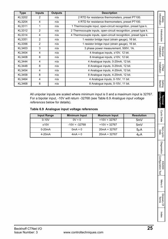
All unipolar inputs are scaled where minimum input is 0 and a maximum input is 32767. For a bipolar input, -10V will return -32768 (see Table 6.9 Analogue input voltage references below for details).
Table 6.9 Analogue input voltage references
KL3202 2 n/a 2 RTD for resistance thermometers, preset PT100.KL3204 4 n/a 4 RTD for resistance thermometers, preset PT100.KL3311 1 n/a 1 Thermocouple input, open-circuit recognition, preset type k.KL3312 2 n/a 2 Thermocouple inputs, open-circuit recognition, preset type k.KL3314 4 n/a 4 Thermocouple inputs, open-circuit recognition, preset type k.KL3351 2 n/a 1 resistor bridge input (strain gauge), 16 bit.KL3356 2 n/a 1 resistor bridge input (strain gauge), 16 bit.KL3403 3 n/a 3 phase power measurement, 500V, 1A.KL3404 4 n/a 4 Analogue inputs, ±10V, 12 bit.KL3408 8 n/a 8 Analogue inputs, ±10V, 12 bit.KL3444 4 n/a 4 Analogue inputs, 0-20mA, 12 bit.KL3448 8 n/a 8 Analogue inputs, 0-20mA, 12 bit.KL3454 4 n/a 4 Analogue inputs, 4-20mA, 12 bit.KL3458 8 n/a 8 Analogue inputs, 4-20mA, 12 bit.KL3464 4 n/a 4 Analogue inputs, 0-10V, 11 bit.KL3468 8 n/a 8 Analogue inputs, 0-10V, 11 bit.
Type Inputs Outputs Description
Input Range Minimum Input Maximum Input Resolution0-10V 0V = 0 +10V = 32767 5mV±10V -10V = -32768 +10V = 32767 5mV
0-20mA 0mA = 0 20mA = 32767 5μA4-20mA 4mA = 0 20mA = 32767 4μA
Beckhoff CTNet I/O 25Issue Number: 3 www.controltechniques.com
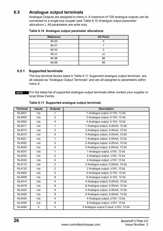
6.5 Analogue output terminalsAnalogue Outputs are assigned to menu 4. A maximum of 100 analogue outputs can be connected to a single bus coupler (see Table 6.10 Analogue output parameter allocations ). All parameters are write only.
Table 6.10 Analogue output parameter allocations
6.5.1 Supported terminalsThe bus terminal blocks listed in Table 6.11 Supported analogue output terminals are all classed as “Analogue Output Terminals” and are all assigned to parameters within menu 4.
Table 6.11 Supported analogue output terminals
Reference I/O Point#4.00 0#4.01 1#4.02 2#4.xx xx#4.98 98#4.99 99
For the latest list of supported analogue output terminals either contact your supplier or local Drive Centre.
NOTE
Terminal Inputs Outputs DescriptionKL4001 n/a 1 1 Analogue output, 0-10V, 12 bit.KL4002 n/a 2 2 Analogue output, 0-10V, 12 bit.KL4004 n/a 4 4 Analogue output, 0-10V, 12 bit.KL4011 n/a 1 1 Analogue output, 0-20mA, 12 bit.KL4012 n/a 2 2 Analogue output, 0-20mA, 12 bit.KL4014 n/a 4 4 Analogue output, 0-20mA, 12 bit.KL4021 n/a 1 1 Analogue output, 4-20mA, 12 bit.KL4022 n/a 2 2 Analogue output, 4-20mA, 12 bit.KL4024 n/a 4 4 Analogue output, 4-20mA, 12 bit.KL4031 n/a 1 1 Analogue output, ±10V, 12 bit.KL4032 n/a 2 2 Analogue output, ±10V, 12 bit.KL4034 n/a 4 4 Analogue output, ±10V, 12 bit.KL4112 n/a 2 2 Analogue output, 0-20mA, 15 bit.KL4132 n/a 2 2 Analogue output, ±10V, 12 bit.KL4404 n/a 4 4 Analogue output, 0-10V, 12 bit.KL4408 n/a 8 8 Analogue output, 0-10V, 12 bit.KL4414 n/a 4 4 Analogue output, 0-20mA, 12 bit.KL4418 n/a 8 8 Analogue output, 0-20mA, 12 bit.KL4424 n/a 4 4 Analogue output, 4-20mA, 12 bit.KL4428 n/a 8 8 Analogue output, 4-20mA, 12 bit.KL4434 n/a 4 4 Analogue output, ±10V, 12 bit.KL4438 n/a 8 8 Analogue output, ±10V, 12 bit.KL4494 2 2 2 Analogue output 2 input, ±10V, 12 bit.
26 Beckhoff CTNet I/Owww.controltechniques.com Issue Number: 3

Safety Inform
ationIntroduction
Electrical Installation
CTN
et Installation
Getting
StartedTerm
inal C
onfigurationC
yclic Data
Non-cyclic D
ataD
iagnosticsKS2000
Configuration Tool
Menu 0
Glossary O
f Term
sIndex
6.6 Special function input terminalsA maximum of 100 special function input channels can be connected to a BK7200 CTNet bus coupler.
Process data exchanges are carried out through parameters #5.00 to #5.99, where each of these parameters represents a channel on the terminal bus. Each individual terminal determines the format of the process data that is to be used. Particular terminals may have their control/status byte as the least significant byte.
Register communication with the internal data structure of special function terminals can be achieved through Beckhoffs own KS2000 software.
6.7 Special function output terminalsA maximum of 100 special function outputs can be connected to a BK7200 CTNet bus coupler.Process data exchanges are carried out through parameters #6.00 to #6.99, where each of these parameters represents a channel on the terminal bus. Each individual terminal determines the format of the process data that is to be used. Particular terminals may have their control/status byte as the Least Significant Byte.
Register communication with the internal data structure of special function terminals can be achieved through Beckhoffs own KS2000 software.
Beckhoff CTNet I/O 27Issue Number: 3 www.controltechniques.com

6.8 Large terminalsFigure 6-1 KM2008 large digital output terminal shows a KM2008 large digital output terminal.
• The Beckhoff KM2008 is a large digital output terminal giving access to up to 64 digital outputs from the same terminal.
• The first column of blocks on the KM2008 (the top left and bottom left) contain 16 digital outputs, these are represented by bits 0 - 15 of parameter #2.00.
• The second column represent bits 0 - 15 of parameter #2.01.• The third column represent bits 0 - 15 of parameter #2.02.• And the fourth and final column represent bits 0 - 15 of parameter #2.03.• The lights to the left of each of the digital output channels light up when the
specific channel is enabled.
Large digital output terminals such as the KM2008 operate as any other digital output terminal.
Figure 6-1 KM2008 large digital output terminal
There are also large digital input terminals such as the KM1002. These large terminals only take up 1 of the allocated maximum 64 terminals on the K-bus allowing for easy referencing of specific channels.
28 Beckhoff CTNet I/Owww.controltechniques.com Issue Number: 3
Safety Inform
ationIntroduction
Electrical Installation
CTN
et Installation
Getting
StartedTerm
inal C
onfigurationC
yclic Data
Non-cyclic D
ataD
iagnosticsKS2000
Configuration Tool
Menu 0
Glossary O
f Term
sIndex
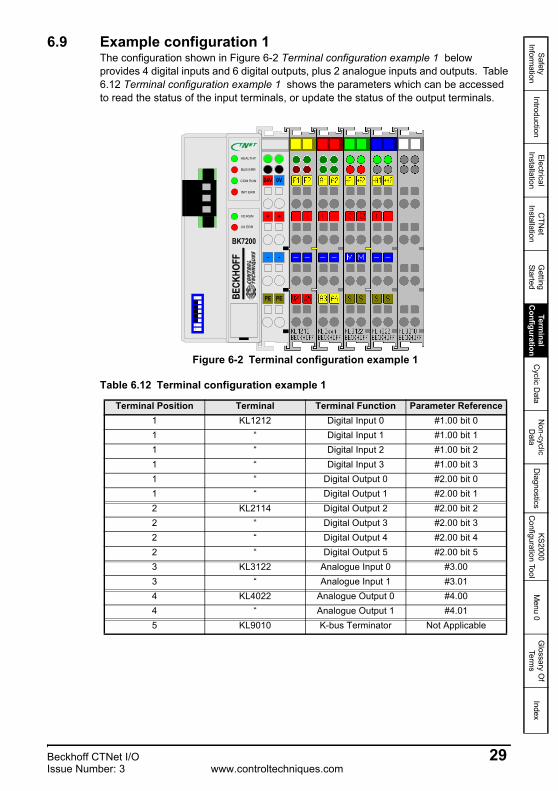
6.9 Example configuration 1The configuration shown in Figure 6-2 Terminal configuration example 1 below provides 4 digital inputs and 6 digital outputs, plus 2 analogue inputs and outputs. Table 6.12 Terminal configuration example 1 shows the parameters which can be accessed to read the status of the input terminals, or update the status of the output terminals.
Figure 6-2 Terminal configuration example 1
Table 6.12 Terminal configuration example 1
Terminal Position Terminal Terminal Function Parameter Reference1 KL1212 Digital Input 0 #1.00 bit 01 “ Digital Input 1 #1.00 bit 11 “ Digital Input 2 #1.00 bit 21 “ Digital Input 3 #1.00 bit 31 “ Digital Output 0 #2.00 bit 01 “ Digital Output 1 #2.00 bit 12 KL2114 Digital Output 2 #2.00 bit 22 “ Digital Output 3 #2.00 bit 32 “ Digital Output 4 #2.00 bit 42 “ Digital Output 5 #2.00 bit 53 KL3122 Analogue Input 0 #3.003 “ Analogue Input 1 #3.014 KL4022 Analogue Output 0 #4.004 “ Analogue Output 1 #4.015 KL9010 K-bus Terminator Not Applicable
24V
+
-
PE
0V
+
-
PEBECK
HOFF
Ν
BK7200
0 1
1
8
HEALTHY
BUS ERR
COM RUN
INIT ERR
I/O RUN
I/O ERR
Beckhoff CTNet I/O 29Issue Number: 3 www.controltechniques.com

6.10 Example configuration 2The configuration in Figure 6-3 Terminal configuration example 2 has been extended to provide 10 digital inputs and 14 digital outputs, plus 15 analogue inputs and 4 analogue outputs. The arrows shown at the bottom of Figure 6-3 indicate the new positions of the terminals used in Figure 6-2 Terminal configuration example 1 on page 29. Table 6.13 Terminal configuration example 2 on page 31 shows the parameters which have been assigned to the terminals which can be accessed to read the status of the input terminals, or update the status of the output terminals.
Figure 6-3 Terminal configuration example 2
30 Beckhoff CTNet I/Owww.controltechniques.com Issue Number: 3

Safety Inform
ationIntroduction
Electrical Installation
CTN
et Installation
Getting
StartedTerm
inal C
onfigurationC
yclic Data
Non-cyclic D
ataD
iagnosticsKS2000
Configuration Tool
Menu 0
Glossary O
f Term
sIndex
Table 6.13 Terminal configuration example 2
Digital inputs and outputs should be grouped together, as they need to have power supplied through the power contacts to drive external relays, etc. Voltage output analogue modules do not use the power contacts, so they should be placed at the end of the line of terminals but before the K-bus terminator terminal which must always be last.
It can be seen that the digital input and output terminals have been fitted BEFORE the analogue terminals. However, this does not affect the addressing of the analogue input and output terminals which occurs when the K-bus first scans the terminals during initialisation, although the analogue input terminal will now be the 6th terminal to be found, it is still the 1st analogue input terminal. Therefore, when it is entered into the database, both inputs will be assigned the first available parameter numbers in menu 3, which will still be 0 and 1. Hence, there is no change in the terminal address. As additional analogue input modules are added, they will get the next available parameters in menu 3.
KLxxxx
Terminal Input/Output Function
Parameter Reference
KLxxxx
Terminal Input/Output Function
Parameter Reference
1 KL1002 Digtal Input 0 #1.00 bit 0 5 “ Digital Output 12 #2.00 bit 12
1 “ Digital Input 1 #1.00 bit 1 5 “ Digital Output 13 #2.00 bit 13
2 KL1212 Digital Input 2 #1.00 bit 2 6 KL3122 Analogue Input 0 #3.002 “ Digital Input 3 #1.00 bit 3 6 “ Analogue Input 1 #3.01
2 “ Digital Input 4 #1.00 bit 4 7 KL3311 Analogue Input 2 #3.02
2 “ Digital Input 5 #1.00 bit 5 8 KL3314 Analogue Input 3 #3.032 “ Digital Output 0 #2.00 bit 0 8 “ Analogue Input 4 #3.04
2 “ Digital Output 1 #2.00 bit 1 8 “ Analogue Input 5 #3.05
3 KL1114 Digital Input 6 #1.00 bit 6 8 “ Analogue Input 6 #3.063 “ Digital Input 7 #1.00 bit 7 9 KL3448 Analogue Input 7 #3.07
3 “ Digital Input 8 #1.00 bit 8 9 “ Analogue Input 8 #3.08
3 “ Digital Input 9 #1.00 bit 9 9 “ Analogue Input 9 #3.094 KL2114 Digital Output 2 #2.00 bit 2 9 “ Analogue Input 10 #3.10
4 “ Digital Output 3 #2.00 bit 3 9 “ Analogue Input 11 #3.11
4 “ Digital Output 4 #2.00 bit 4 9 “ Analogue Input 12 #3.124 “ Digital Output 5 #2.00 bit 5 9 “ Analogue Input 13 #3.13
5 KL2408 Digital Output 6 #2.00 bit 6 9 “ Analogue Input 14 #3.14
5 “ Digital Output 7 #2.00 bit 7 10 KL4012 Analogue Output 0 #4.005 “ Digital Output 8 #2.00 bit 8 10 “ Analogue Output 1 #4.01
5 “ Digital Output 9 #2.00 bit 9 11 KL4022 Analogue Output 2 #4.02
5 “ Digital Output 10 #2.00 bit 10 11 “ Analogue Output 3 #4.035 “ Digital Output 11 #2.00 bit 11 12 KL9010 K-bus Terminator Not Applicable
When adding input and output terminals to a bus coupler, ensure that each type of input is added after the last terminal block of a similar type. This will ensure that all existing terminal and parameter mappings will not be affected.
NOTE
Table 6.13 above terminals KL1212, KL2114, KL3122 and KL4022 have been highlighted to show the new positions of the terminals from Table 6.12 Terminal configuration example 1 on page 29.
NOTE
Beckhoff CTNet I/O 31Issue Number: 3 www.controltechniques.com

7 Cyclic DataSyPT Pro must be used to configure a BK7200 module to transmit cyclic data over the CTNet network. SyPT provides a graphical network configuration tool, which displays all configured cyclic links between nodes. This manual assumes that the user has a basic knowledge of using SyPT to configure CTNet networks. For more information refer to the CTNet user guide.
7.1 Fast and slow cyclic data channelsTo configure cyclic data transfers, “data links” must be defined for either fast or slow cyclic data channels. Each link is configured to transmit a defined set of consecutive registers or parameters from within a particular menu in the BK7200, to a defined set of consecutive registers or parameters in the target node. This process is known as “binding” registers together.
There are two limitations when defining the cyclic data links to be transmitted and the number of registers to be transmitted by the BK7200 module:
1. A maximum of 20 separate links can be defined for a single node. This total includes both fast and slow data links.
2. No individual link may transfer more than 20 consecutive registers.
Each link runs on successive token rotations. The first defined link is transmitted on the first token rotation after the “synchronisation message”, the next link on the next token rotation and so on.
7.2 Cyclic/Non-cyclic data - time allocationsFigure 7-1 below shows a typical example of time allocation of cyclic and non-cyclic data over an 80ms period on CTNet. The example below is set-up such is that the fast cyclic reads occur every 10ms and the slow cyclic reads occur every 50ms (#MM.25 of the SM-Applications producing the cyclic data rates = 510). As you can see the fast cyclic data runs each time 10ms elapses, after 50ms the fast cyclic reads occur as usual and then the slow cyclic reads occur straight after all fast cyclic reads have finished (fast cyclic reads always finish before the slow cyclic reads can start). The area depicted by the grey area in Figure 7-1 represents slack time not used by the cyclic data, this is available for use by any non-cyclic data (so long as the fast/slow cyclic reads do not take up all available time between each set of reads).
Figure 7-1 Cyclic/Non-cyclic time allocations
800
Key:
Milliseconds
Spare time availablefor non-cyclic data
10 20 30 40 50 60 70
Fast cyclic read Slow cyclic read
32 Beckhoff CTNet I/Owww.controltechniques.com Issue Number: 3

Safety Inform
ationIntroduction
Electrical Installation
CTN
et Installation
Getting
StartedTerm
inal C
onfigurationC
yclic Data
Non-cyclic D
ataD
iagnosticsKS2000
Configuration Tool
Menu 0
Glossary O
f Term
sIndex
7.3 Overloading network nodesCare must be taken when configuring a network to ensure that the BK7200 does not get overloaded with incoming messages. The BK7200 is capable of processing up to 4 messages every millisecond (4000 messages per second). If the module is overloaded with incoming messages, messages may be lost before they can be processed and the cyclic data transfer may be corrupted. The number of messages arriving over CTNet can be monitored in #0.02 in the BK7200 bus coupler (see Chapter 11.1 Menu 0 parameters on page 48 for more information).
The K-bus and CTNet are asynchronous meaning the terminal update time via the serial K-bus will decrease as the CTNet message loading increases and this can be monitored in #0.03 in the BK7200. The balance between the CTNet cyclic data update and the K-bus terminal update time depends on both the amount of CTNet messages to be processed and the number of terminals connected to the coupler.
A good example of this is where the BK7200 could become overloaded when every node on the network is sending cyclic data to the BK7200. On a large network, say 50 drives, this can mean that the bus coupler suddenly receives 50 messages in very quick succession, cannot process them quickly enough and loses some of the messages. The effect of the lost messages could indicate to the monitoring node that several drives are not functioning, when this is not actually the case and all nodes are operating correctly.
7.3.1 AliasingAliasing is a signal processing term. Aliasing occurs when a system is measured at an insufficient sampling rate. It is perhaps best explained through example.
Figure 7-1 below shows a switch with the lower position being ‘Off’ and at its higher position the switch is ‘On’. Below the signal of the switch is the sample rate for the signal of the switch and the actual measured signal are not the same, most importantly the area circled below where the switch was turned on for a short period of time was missed by the measured signal because the signal was not sampled within this time.
Figure 7-2 Aliasing example
Beckhoff CTNet I/O 33Issue Number: 3 www.controltechniques.com

7.4 Asynchronous samplingIn this section the following shorthand expressions will be used:
fCyclicDataRate = Parameter #0.02 of the Beckhoff 7200 bus coupler (CTNet cycles per second).
fk-bus = Parameter #0.03 of the Beckhoff 7200 bus coupler (K-bus cycles per second).
No sample will be missed over CTNet if fk-bus > fCyclicDataRate and fCyclicDataRate > 0.
fCyclicDataRate is the amount of the cycles per second of fast and slow cyclic data, as well as non-cylic data.
To decrease the time between the sample on the k-bus and the value being received over CTNet, modify the CTNet sync set-up (#MM.25) on the SM-Applications (i.e. fast and slow cyclic data) ensuring fk-bus > fCyclicDataRate.
7.4.1 Sample rate example 1This is a simple example describing the steps which would need to be calculated in order to read an analogue signal, maximum frequency of 100Hz over fast cyclic data without aliasing (missing transitions).
If parameter #MM.25 of the SM-Applications module has a value of ‘1005’, this would mean that fast cyclic communications would be set-up to run every 5ms and slow cyclic communications to run every 50ms (10ms * 5ms).
fCyclicDataRate would read 200, assuming that fk-bus > fCyclicDataRate (fast cyclic data component), then there would be no aliasing due to the k-bus; this is calculated as follows:
The highest possible frequency that can be sampled =
fCyclicDataRate (fast cyclic data component) = 200 / 2 = 100Hz
This means that no aliasing of the signal will occur by anything other than the ‘Analogue to Digital Converter’ (ADC) in the analogue terminal (see specification for ADC sample rate in module documentation).
This example is for fast cyclic communications, if we wanted to use slow cyclic communications to transfer the signal, the calculation is as follows:
The highest frequency that could be sampled =
fCyclicDataRate (slow cyclic data component) = 20 / 2 = 10 Hz
In this example there will be aliasing apparent in the signal received over CTNet, for every 10 cycles of the 100Hz signal, only one sample would be read. This may be acceptable if the data being received over CTNet is non-urgent, or only processed in a low priority task, tolerating aliasing will reduce the need for high speed cyclic data, thus reducing CTNet traffic.
34 Beckhoff CTNet I/Owww.controltechniques.com Issue Number: 3

Safety Inform
ationIntroduction
Electrical Installation
CTN
et Installation
Getting
StartedTerm
inal C
onfigurationC
yclic Data
Non-cyclic D
ataD
iagnosticsKS2000
Configuration Tool
Menu 0
Glossary O
f Term
sIndex
7.5 Setting up the BK7200 for cyclic communications7.5.1 Introduction
Chapter 7.5.3 Example configuration shows a step-by-step process of how to set up the BK7200 bus coupler for cyclic communications.
7.5.2 Required equipment• Beckhoff BK7200 CTNet bus coupler.• Beckhoff input terminals.• Beckhoff output terminals.• Beckhoff bus end terminal (e.g. KL9010).• SyPT Pro.• Unidrive SP (or any other drive with CTNet capability).• SM-Applications module (or any other module with CTNet capability).
7.5.3 Example configurationBelow shows the set-up which will be used for the following example of how to set-up cyclic communications on a BK7200 CTNet bus coupler.
The set-up contains a BK7200 CTNet bus coupler (plus any connected terminals) connected via CTNet to an SM-Applications module inserted on a Unidrive SP, the Unidrive SP is then connected via the CT USB to RS485 communications cable (part number: 4500-0096) to a PC with SyPT Pro installed, this will allow the use of SyPT Pro to configure any cyclic communications on the network.
Figure 7-3 BK7200 network configuration
BK7200 CTNetbus coupler
Unidrive SP with anSM-Applications
fitted
PC with SyPTPro installed
24 V
+
-
PE
0V
+
-
PEBECK
HOFF
Ν
BK7200
0 1
1
8
HEALTHY
BUS ERR
COM RUN
INIT ERR
I/O RUN
I/O ERR
Beckhoff CTNet I/O 35Issue Number: 3 www.controltechniques.com

Once the SyPT Pro application software has been started and the configuration is set-up as required, you should have a configuration that at the least contains a Unidrive SP with an SM-Applications module (or any other CTNet compatible drive) plus a BK7200 CTNet bus coupler connected via CTNet as shown in Figure 7-4.
Figure 7-4 SyPT Pro set-up
The icon shown is the ‘Cyclic Data’ icon, click on it, this will open the cyclic data window shown in Figure 7-5.
Figure 7-5 Cyclic data links window
Figure 7-5 shows (if any) the cyclic data links that are set-up between nodes, as you can see from Figure 7-4 on page 36 node 9 is an SM-applications module on the Unidrive SP and node 5 is the Beckhoff BK7200 CTNet bus coupler. The left hand matrix shows all current links between all nodes and the table situated on the right hand side shows links from specific node to node relationships.
In order to create a cyclic link with a source of the BK7200 coupler and a destination of the SM-applications module, you must ensure that SyPT pro is offline.
Next as shown in Figure 7-6, as the beckhoff coupler is the source of the link, parameter #1.00 will be the source, the reason being that the input terminal which cyclic communications will be set-up on is a digital input KL1114 which is the first digital input terminal on the K-bus, the first channel of this terminal will be linked to incoming PLC register _S00% of the SM-Applications module (_S00% could have also been represented as #73.00). You can see that there is also the option of whether or not you want SLOW or FAST cyclic communications.
36 Beckhoff CTNet I/Owww.controltechniques.com Issue Number: 3

Safety Inform
ationIntroduction
Electrical Installation
CTN
et Installation
Getting
StartedTerm
inal C
onfigurationC
yclic Data
Non-cyclic D
ataD
iagnosticsKS2000
Configuration Tool
Menu 0
Glossary O
f Term
sIndex
Figure 7-6 Entering a cyclic data link (1)
As shown in Figure 7-7, the SM-Applications is the source of the link, to make programming easier in terms of continuity it makes sense to start at the first available parameter, which in this case would be OUT PLC register 0 (_R00% or #72.00). This PLC register will be linked to parameter #2.00 of the BK7200 bus coupler (this represents the first 16 bits of digital outputs on the bus coupler). These is also an option as to whether you want slow or fast cyclic communications.
Figure 7-7 Entering a cyclic data link (2)
7.5.4 Downloading the cyclic data links to the SM-Applications1. Next, save the project.2. Click the ‘Project’ drop-down list, then ‘Rebuild All’ to add the cyclic links to the
nodes.3. Go back ‘on-line’.4. Select ‘Project’, ‘Download All’, then ‘OK’, to send the cyclic links to the nodes.5. You may notice that a red warning box has appeared under the cyclic link table
stating that the ‘link defined in SYPT but not present in target. If this happens then you need to do to get rid of the warning, select ‘Project’, ‘Download’, choose the nodes you wish to download, which in this case is all of them, click ‘OK’.
Figure 7-8 Cyclic link defined in target but not present in node
6. The warning will now be cleared.7. Your cyclic communications should now be successfully set-up, see section
7.5.5 Checking the cyclic links on page 38 for more information on how to check that your cyclic links are correctly functioning.
Beckhoff CTNet I/O 37Issue Number: 3 www.controltechniques.com

7.5.5 Checking the cyclic linksAn easy way to check whether or not the cyclic communications are configured successfully is as follows:
• While the cyclic communications are running, open the ‘Watch window’ in SyPT (shown in Figure 7-9 below).
Figure 7-9 Watch Window (1)
• Click the ‘New Item’ icon and the new item window will open as shown in Figure 7-10.
Figure 7-10 Add new item to the Watch Window
38 Beckhoff CTNet I/Owww.controltechniques.com Issue Number: 3

Safety Inform
ationIntroduction
Electrical Installation
CTN
et Installation
Getting
StartedTerm
inal C
onfigurationC
yclic Data
Non-cyclic D
ataD
iagnosticsKS2000
Configuration Tool
Menu 0
Glossary O
f Term
sIndex
7.5.6 Testing the cyclic communications1. Firstly select the ‘Node’ which represents the Beckhoff bus coupler, which in this
instance is node 5. 2. In the ‘Name’ category type in ‘#1.00’.3. Under the ‘Display’ area tick the ‘Bit Field’ check box.4. Click ‘OK’5. Open the ‘New Item’ window again, but this time in the ‘Name’ category type in
‘_S00%’ and the node should be set to that of the SM-Applications module which in this example is node 9.
6. Again click ‘OK’.7. The watch window should now look as shown in Figure 7-11.
Figure 7-11 Watch Window (2)
8. In the lower half of the watch window titled ‘Immediate Window’ type in the following, ‘#2.00 = 0x00010001’, this is to enable the mask settings for the digital output terminal.
9. Once all of the previous steps are completed in order, join contact 1 of the KL1114 digital input terminal to contact 1 of the KL2408 digital output terminal, you will notice that parameter #1.00 of the watch window updates to a value of ‘1’.
Beckhoff CTNet I/O 39Issue Number: 3 www.controltechniques.com

40 Beckhoff CTNet I/Owww.controltechniques.com Issue Number: 3
8 Non-cyclic DataThis non-cyclic data is particularly useful for transmitting infrequent events around the network. The BK7200 CTNet bus coupler cannot issue these commands as it does not run DPL programs, but it will respond to non-cyclic RDNET, WRNET and CHECKNODE commands issued by other nodes on the network.
A typical example where non-cyclic data may be used is on a large network for infrequent data, such as a switch to engage a pinch roller when the line is ready to start. Response time to changing the switch is not critical, since it may take several seconds for the roller to engage. Once the roller is engaged, there is no need to transmit any information about the switch over the network until the switch changes state. This provides a large reduction in the network bandwidth used for this signal and increases the bandwidth available for other data signals.
Depending on the application it may be advisable to check the status of outputs that are controlled from time to time and to check the state of inputs more than once to allow for noise, etc.
NOTE

Safety Inform
ationIntroduction
Electrical Installation
CTN
et Installation
Getting
StartedTerm
inal C
onfigurationC
yclic Data
Non-cyclic D
ataD
iagnosticsKS2000
Configuration Tool
Menu 0
Glossary O
f Term
sIndex
9 Diagnostics
9.1 Beckhoff BK7200 bus coupler firmware versionThere are two simple ways of which to check the currently installed version of firmware on the Beckhoff bus coupler, both through the use of SyPT:
1. In the SyPT watch window function view parameters #0.01 and #0.04, parameter #0.01 makes up part XXYY and parameter #0.04 makes up part ZZ, to make up the six digit firmware version in the form XXYYZZ.e.g. If parameter #0.01 had a value of ‘104’ and parameter #0.04 had a value of ‘11’, then the firmware version would be ‘01.04.11’.
2. Again in SyPT, so long as the project is online, from the ‘Project’ menu choose ‘Identify Node’, along side the description of ‘Core/system’ will be the currently installed firmware version.
9.1.1 Updating the firmware
The BK7200 bus coupler’s firmware can be updated through the use of either the Beckhoffs own ‘KS2000’ terminal configuration application or an equally effective DOS firmware updater which is available from your supplier or local drive centre. The correct cable must be used see Chapter 5.8 Beckhoff coupler programming cable on page 17 for more information.
1. To update the firmware through KS2000, the communications between the bus coupler and the PC must be set-up correctly. From the ‘Online’ drop-down list, select ‘Coupler’ and then ‘Firmware Update’. A new page will open, on the right-hand side of the page is a button labelled ‘Select’, this is where you can choose the required firmware file, finally click ‘Start’ to update the firmware.
2. The BK7200 bus coupler can also be updated through ‘Firmware Update V1.0’ which is available from your supplier or local drive centre, execute the program, select the relevant COM port, enter the filename of the applicable firmware file and select ‘Load’.
The firmware file must be present in the same folder that the ‘firmware update V1.0.exe’ file is being ran from.
The filename of the .hex firmware file, must be no longer than 12 characters long, this includes the ‘.hex’ file extension.
e.g. V010400.hex would be ok
mynewhexfile.hex would not
NOTE
Beckhoff CTNet I/O 41Issue Number: 3 www.controltechniques.com

9.2 Diagnostic LEDsThe terminals attached to the bus coupler are checked when it is first switched on. A correct start-up procedure is indicated by the red LED “I/O ERR” going out. If this LED is flashing, then there is a fault somewhere along the K-bus. The position of the problem can be decoded by observing the flashing lights with the help of Table 9.1 Diagnostic LEDs look-up table .
The two green lights on the top right of the BK7200 bus coupler are there to indicate the voltage supply. The left sided LED shows the 24V supply of the bus coupler, while the right sided LED shows the supply (if any) to the power contacts.
9.3 Error codes and their meaningsThe two I/O LEDs located at the bottom of the row of LEDs on the BK7200 bus coupler are used to display the operating mode of the bus terminals and the connections interlocking the bus terminals on the bus. When the green LED is lit up this means that the communications with the fieldbus system is working correctly, however if the red LED is lit up then there is a fault somewhere on the bus (see Table 9.1 Diagnostic LEDs look-up table for more information).
Table 9.1 Diagnostic LEDs look-up table
LED Significance RemedyHEALTHY BUS ERR COM RUN INIT ERR
off off off off Fieldbus configuring. Wait while the fieldbus boots up.
off off off flashing A serious error occured during the initialisation of the fieldbus, this is most likely caused by memory or configuration errors.
Check:1. Baud rate DIP switches
are correctly set.2. Ensure you have the
latest firmware installed.on off off off The configuration of the
fieldbus has been successful, however no messages are being received at present.
Check:1. If cyclic data is required
ensure that there is a sync master on the CTNet network.
2. That messages are being directed to the coupler.
on off on off The BK7200 is currently receiving messages over the CTNet network
Nothing, everthing is currently working correctly.
on on off on The BK7200 is currently initiating a CTNet RECON.
Check:1. The CTNet cable is
plugged into the coupler.2. That there is at least one
other node operating on the network.
3. That the bus cable is intact.
on on off off CTNet RECON occurring When a node is removed or inserted onto a network, then a RECON will occur.
42 Beckhoff CTNet I/Owww.controltechniques.com Issue Number: 3
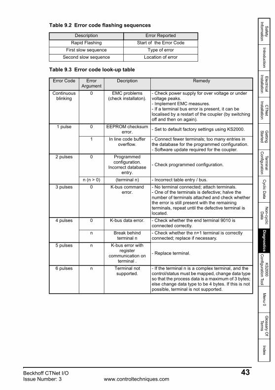
Safety Inform
ationIntroduction
Electrical Installation
CTN
et Installation
Getting
StartedTerm
inal C
onfigurationC
yclic Data
Non-cyclic D
ataD
iagnosticsKS2000
Configuration Tool
Menu 0
Glossary O
f Term
sIndex
Table 9.3 Error code look-up table
Table 9.2 Error code flashing sequences
Description Error ReportedRapid Flashing Start of the Error Code
First slow sequence Type of errorSecond slow sequence Location of error
Error Code Error Argument
Decription Remedy
Continuous blinking
0 EMC problems (check installaton).
- Check power supply for over voltage or under voltage peaks.- Implement EMC measures.- If a terminal bus error is present, it can be localised by a restart of the coupler (by switching off and then on again).
1 pulse 0 EEPROM checksum error. - Set to default factory settings using KS2000.
1 In line code buffer overflow.
- Connect fewer terminals; too many entries in the database for the programmed configuration.- Software update required for the coupler.
2 pulses 0 Programmed configuration.
Incorrect database entry.
- Check programmed configuration.
n (n > 0) (terminal n) - Incorrect table entry / bus.3 pulses 0 K-bus command
error.- No terminal connected; attach terminals.- One of the terminals is defective; halve the number of terminals attached and check whether the error is still present with the remaining terminals, repeat until the defective terminal is located.
4 pulses 0 K-bus data error. - Check whether the end terminal 9010 is connected correctly.
n Break behind terminal n
- Check whether the n+1 terminal is correctly connected; replace if necessary.
5 pulses n K-bus error with register
communication on terminal .
- Replace terminal.
6 pulses n Terminal not supported.
- If the terminal n is a complex terminal, and the control/status must be mapped, change data type so that the process data is a maximum of 3 bytes; else change data type to be 4 bytes. If this is not possible, terminal is not supported.
Beckhoff CTNet I/O 43Issue Number: 3 www.controltechniques.com

9.4 Location of errorThe position of the last terminal before the error is represented by the number of flashes occuring, this does not include passive bus terminals such as power input terminals see Table 9.3 Error code look-up table on page 43.
Even when the fault has been cleared, the LED will not stop flashing and the operating mode will remain at stop until the bus coupler has been reset.
It is not advisable to plug or unplug terminals into the bus coupler without first ensuring that the power is off.
9.5 Cannot establish CTNet connectionThe following steps should be used when attempting to diagnose problems on CTNet networks:
1. Ensure that the correct type of cable is used. CTNet runs at very high data rates, and consequently requires high quality cable. Performance cannot be guaranteed if the specified Control Techniques CTNet cable is not used (support will not be provided where non-approved cable has been used).
2. Termination resistors MUST be fitted. Unpredictable network behaviour may result and the noise immunity of the network will also be severely reduced without proper line termination resistors (82Ω ±1% for the current CTNet cable).
3. Update the firmware of the SM-Applications and the BK7200 CTNet bus coupler.
4. Check the node configuration settings on all nodes. Every node must have a unique node address, all node data rates must be identical and only one drive must be set to generate the synchronisation message.
5. Ensure that the data rate selected is allowed for the length of network cable installed. If necessary, try reducing the network data rate at all nodes to establish communications. Repeaters may be required to extend the network length for a given data rate.
6. Refer to the CTNet manual for CTNet network maximum lengths. If more than 32 unit loads are connected to a single section of cable, network repeaters will be required. Network repeaters affect the maximum number of unit loads on each section of cable.
Some terminals may appear as two terminals on the bus, terminals with this behaviour are documented as so in its relevant data sheet.
NOTE
44 Beckhoff CTNet I/Owww.controltechniques.com Issue Number: 3

Safety Inform
ationIntroduction
Electrical Installation
CTN
et Installation
Getting
StartedTerm
inal C
onfigurationC
yclic Data
Non-cyclic D
ataD
iagnosticsK
S2000 C
onfiguration ToolM
enu 0G
lossary Of
Terms
Index
10 KS2000 Configuration Tool
10.1 KS2000 introductionThe KS2000 configuration software permits commissioning and parameterisation of the Beckhoff Fieldbus modules and of the Beckhoff Bus Terminals. The connection between the fieldbus components and the PC is established via the connection cable provided with KS2000. The KS2000 configuration software requires Windows NT, 2000 or XP operating systems.
The KS2000 software offers access to the process image of the fieldbus components. In this way it is possible to monitor the input and output images of the Bus Terminals. Access to individual signal channels is supported through a scope functionality.
10.2 KS2000 featuresWhen KS2000 is first run, the screen in Figure 10-1 Beckhoff KS2000 start-up screen will be shown, it is advisable that you check the communication settings of the connection before you attempt to connect to the bus coupler.
Figure 10-1 Beckhoff KS2000 start-up screen
Any changes made to KS2000 may have serious implications, ensure you understand the implications of any changes made.
WARNING
Beckhoff CTNet I/O 45Issue Number: 3 www.controltechniques.com

10.2.1 Changing the communication settings1. From the ‘Options’ drop-down menu, select ‘Communication channel’.2. Next select ‘Via COM’.3. The window as shown in Figure 10-2 will be displayed.4. Choose the COM port you are connecting to the PC.5. Select the relevant baud rate.6. Select whether your connection is either RS232 or RS485.7. Finally to test that the connection to the bus coupler, click the ‘Test...’ button.
Figure 10-2 Communications set-up
If the connection test was succesful, the information box shown in Figure 10-3 will appear.
Figure 10-3 Communication with coupler successful
Once the settings are correctly configured click ‘Ok’.
46 Beckhoff CTNet I/Owww.controltechniques.com Issue Number: 3

Safety Inform
ationIntroduction
Electrical Installation
CTN
et Installation
Getting
StartedTerm
inal C
onfigurationC
yclic Data
Non-cyclic D
ataD
iagnosticsK
S2000 C
onfiguration ToolM
enu 0G
lossary Of
Terms
Index
To go online, click the ‘Online’ button from the KS2000 toolbar. You will be asked if you want to create new XML devices, click ‘OK’ to continue (as shown in Figure 10-4).
Figure 10-4 Create new XML devices
The layout of KS2000 is split up into 2 sections (as shown in Figure 10-5), the left hand side shows a list of the connected terminals, settings and configurations. The right side shows a graphical image of the current terminals connected to the BK7200 bus coupler.
Figure 10-5 Beckhoff KS2000 online - home screen
10.3 Purchasing KS2000To purchase the KS2000 application software contact your supplier or local drive centre.
Beckhoff CTNet I/O 47Issue Number: 3 www.controltechniques.com
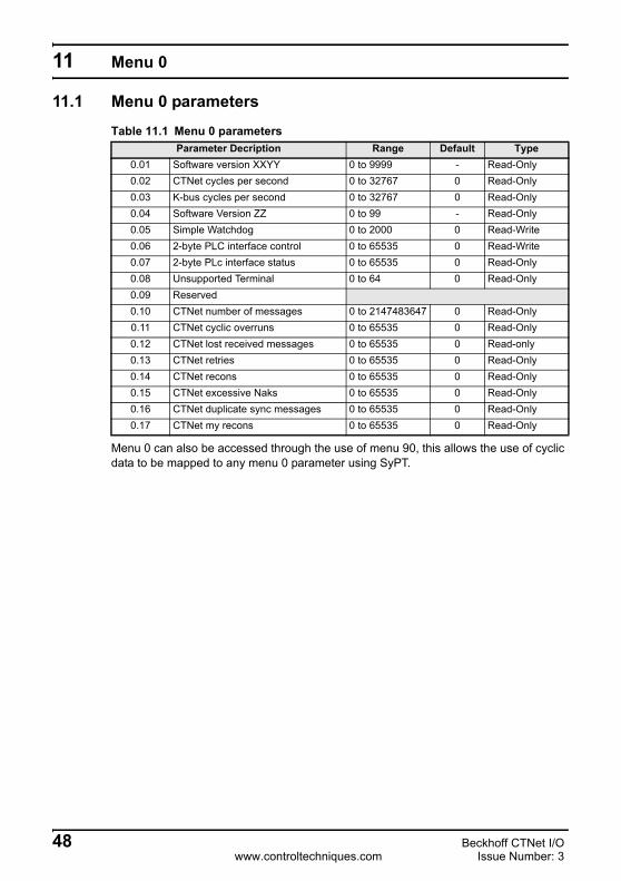
11 Menu 0
11.1 Menu 0 parameters
Menu 0 can also be accessed through the use of menu 90, this allows the use of cyclic data to be mapped to any menu 0 parameter using SyPT.
Table 11.1 Menu 0 parametersParameter Decription Range Default Type
0.01 Software version XXYY 0 to 9999 - Read-Only0.02 CTNet cycles per second 0 to 32767 0 Read-Only0.03 K-bus cycles per second 0 to 32767 0 Read-Only0.04 Software Version ZZ 0 to 99 - Read-Only0.05 Simple Watchdog 0 to 2000 0 Read-Write0.06 2-byte PLC interface control 0 to 65535 0 Read-Write0.07 2-byte PLc interface status 0 to 65535 0 Read-Only0.08 Unsupported Terminal 0 to 64 0 Read-Only0.09 Reserved0.10 CTNet number of messages 0 to 2147483647 0 Read-Only0.11 CTNet cyclic overruns 0 to 65535 0 Read-Only0.12 CTNet lost received messages 0 to 65535 0 Read-only0.13 CTNet retries 0 to 65535 0 Read-Only0.14 CTNet recons 0 to 65535 0 Read-Only0.15 CTNet excessive Naks 0 to 65535 0 Read-Only0.16 CTNet duplicate sync messages 0 to 65535 0 Read-Only0.17 CTNet my recons 0 to 65535 0 Read-Only
48 Beckhoff CTNet I/Owww.controltechniques.com Issue Number: 3

Safety Inform
ationIntroduction
Electrical Installation
CTN
et Installation
Getting
StartedTerm
inal C
onfigurationC
yclic Data
Non-cyclic D
ataD
iagnosticsKS2000
Configuration Tool
Menu 0
Glossary O
f Term
sIndex
11.1.1 #0.01 - Software version XXYYParameter #0.01 of the BK7200 bus coupler contains the first 4 digits of the 6 digit firmware version (more information can be found in section 9.1 Beckhoff BK7200 bus coupler firmware version on page 41).
11.1.2 #0.02 - CTNet cycles per secondParameter #0.02 of the BK7200 bus coupler shows the current rate of CTNet cycles per second being received, the value of this parameter is dependant on the value in the CTNet sync master.
11.1.3 #0.03 - K-bus cycles per secondParameter #0.03 of the BK7200 bus coupler shows the current rate of K-bus cycles per second being received by the bus coupler, with firmware version 01.04.00 of the bus coupler the average speed of the K-bus on the BK7200 is roughly 1700 cycles per second, this is approximately 65% faster than the previous firmware version 01.03.00 (testing based on 3 digital terminals connected to the BK7200 bus coupler).
11.1.4 #0.04 - Software version ZZParameter #0.04 of the BK7200 bus coupler contains the last 2 digits of the 6 digit firmware version, (more information can be found in section 9.1 Beckhoff BK7200 bus coupler firmware version on page 41).
11.1.5 #0.05 - Simple watchdogParameter #0.05 of the BK7200 bus coupler is a read/write parameter, while it has a value of 0 the watchdog function is disabled, if it contains a value in the range of 1 - 2000, then the watchdog is enabled (more information can be found in Chapter 11.2 Watchdog on page 51).
11.1.6 #0.06 - 2-byte PLC interface ControlParameter #0.06 of the BK7200 bus coupler is the control parameter for the 2-byte PLC interface control.
11.1.7 #0.07 - 2-byte PLC interface StatusParameter #0.07 of the BK7200 bus coupler is the status parameter for the 2-byte PLC interface control.
11.1.8 #0.08 - Unsupported terminalParameter #0.08 of the BK7200 bus coupler will contain a value in the range of 0 - 64 and if applicable the value will represent the position of the first unsupported terminal on the K-bus.
11.1.9 #0.09 - ReservedParameter #0.09 of the BK7200 bus coupler is reserved for future use.
K-bus speed is subject to change and is for guidance purposes only.NOTE
Beckhoff CTNet I/O 49Issue Number: 3 www.controltechniques.com

11.1.10#0.10 - CTNet no of messagesParameter #0.10 of the BK7200 bus coupler counts up the added total of CTNet messages sent since the BK7200 bus coupler was last powered up. This parameter is read only.
11.1.11 #0.11 - CTNet cyclic overrunsParameter #0.11 of the BK7200 bus coupler counts up the total amount of cyclic overruns since the BK7200 was last powered up, this is a useful diagnostic parameter and gives a good indication of how healthy the network is. This parameter is read only.
11.1.12#0.12 - CTNet lost Rx messagesParameter #0.12 of the BK7200 bus coupler counts up the number of lost Rx messages since the BK7200 was last powered up. See the CTNet user guide for more information on lost messages. This parameter is read only.
11.1.13#0.13 - CTNet retriesParameter #0.13 of the BK7200 bus coupler counts up the total number of CTNet retries since the BK7200 was last powered up. This parameter is read only.
11.1.14#0.14 - CTNet reconParameter #0.14 of the BK7200 bus coupler is a counter which counts up the total number of reconfigurations since the BK7200 bus coupler was last powered up. See the CTNet user guide for more information on CTNet reconfigurations.
11.1.15#0.15 - CTNet excessive NAKsParameter #0.15 of the BK7200 bus coupler counts up the total number of excessive NAK messages since the BK7200 bus coupler was last powered up. See the CTNet user guide for more information on excessive NAKs. This parameter is read only.
11.1.16#0.16 - CTNet duplicate sync messageParameter #0.16 of the BK7200 bus coupler counts up the total number of duplicate sync messages since the BK7200 was last powered up. See the CTNet user guide for more information on duplicate sync messages.
11.1.17#0.17 - CTNet my reconsParameter #0.17 of the BK7200 bus coupler counts up the total number of CTNet reconfigurations since the BK7200 bus coupler was last powered up. See the CTNet user guide for more information on CTNet my network reconfigurations.
50 Beckhoff CTNet I/Owww.controltechniques.com Issue Number: 3

Safety Inform
ationIntroduction
Electrical Installation
CTN
et Installation
Getting
StartedTerm
inal C
onfigurationC
yclic Data
Non-cyclic D
ataD
iagnosticsKS2000
Configuration Tool
Menu 0
Glossary O
f Term
sIndex
11.2 Watchdog
The Watchdog is a function which provides a safety net, that will automatically reset all Digital Outputs and Analogue Outputs to 0 once a previously set timeout occurs.
In order for the watchdog function to be enabled, one node on the CTNet network must have sent a time-out value in the range of 1 through to 2000 to parameter #0.05 in the bus coupler, if necessary it is possible to write to this paramater through multiple nodes. When parameter #0.05 is written to, the time-out clock is reset to the time out value.
Parameter #0.05 will decrease to 0 if this parameter is not written to before the value reaches 0 all digital and analogue outputs will be reset to 0. For the procedure to work efficently the watchdog time out value should always be set to a value which is 2.5x the maximum cyclic data rate.
To disable the watchdog function at any time, set parameter #0.05 to 0. Everytime the bus coupler is turned on the watchdog value will need to be set again, as parameter #0.05 is reset to 0 during the initialsation process of the bus coupler, subsequently the watchdog is disabled by default.
When using the Watchdog function sure that the safe state for the machine is considered.
CAUTION
The range 1 - 2000 represents 1ms - 2000ms
When using the Watchdog on a network precautions may need to be taken in the controlling node to prevent an intermittent network, causing output to change from the off safe state to the value set in the controlling cyclic data.
NOTE
NOTE
Beckhoff CTNet I/O 51Issue Number: 3 www.controltechniques.com

11.2.1 Watchdog exampleFigure 11-1 shows the watchdog function in action. Remote nodes reset the timer (shown at points 1, 2, 3 and 4) to its original value of 2000 before parameter #0.05 reaches zero. At point 5, the connection to the CTNet network has been lost, therefore parameter #0.05 does not get updated again. When this parameter has reached zero, all analogue and digital outputs are reset to 0 or OFF respectively.
Figure 11-1 Example Watchdog set-up
11.3 Unsupported terminalTo find out whether or not there is one or more unsupported terminals connected to the bus coupler, check parameter #0.08, if the value is any value other than 0 then the value present indicates the position of the first unsupported terminal. See section 9.2 Diagnostic LEDs on page 42 and section 9.3 Error codes and their meanings on page 42 for more details.
It is important to be aware that the Watchdog function should only be used in suitable scenarios, it will not always be advisable to enable the watchdog function as in some circumstances it could be dangerous to reset all outputs to ‘0’ (e.g. an anchor on a ship).
It is the responsibility of the system integrator to ensure that the complete system is safe under all circumstances.
NOTE
NOTE
0.4 0.8 1.2 1.6 2.0 2.4 2.8 3.2 3.60.0
0
200
400
600
800
1000
1200
1400
1600
1800
2000 1 2 3 4 5Pr 0.05
Time (s)
52 Beckhoff CTNet I/Owww.controltechniques.com Issue Number: 3

Safety Inform
ationIntroduction
Electrical Installation
CTN
et Installation
Getting
StartedTerm
inal C
onfigurationC
yclic Data
Non-cyclic D
ataD
iagnosticsKS2000
Configuration Tool
Menu 0
Glossary O
f Term
sIndex
11.4 2-byte PLC interfaceThe 2-byte PLC interface is provided to enable register communication with the internal register structure of complex terminals and the coupler.
Table 11.2 2-byte PLC interfaceByte Bit address ValuesOutput Byte 0 0.0 Toggle bit 0/1
0.1 ---0.2 Toggle bit Reset Request 0/10.3 - 0.7 Function Code
Output Byte 1 Data byte is Write Request 0 - 255
Input Byte 0 0.0 Toggle bit 0/10.1 ---0.2 Reset Acknowledge bit 0/10.3 Error bit (Routing / Write protect) 0/1
Input Byte 1 Data byte is Read Request
Table 11.3 2-byte PLC interface function codesFunction codes 0.7 0.6 0.5 0.4 0.3Send Terminal Number 1 0 0 0 0Send Table Number 1 0 0 0 1Send Register Number 1 0 0 1 0Write Low Byte 1 0 0 1 1Write High Byte 1 0 1 0 0Write High Byte and Increment Register Address 1 0 1 0 1Read Low Byte 0 0 0 1 1Read High Byte 0 0 1 0 0Read High Byte and Increment Register Address 0 0 1 0 1
Menu 0 / Menu 90 is still available for access when the coupler has discovered an unsupported terminal on the bus coupler’s line. This allows diagnostic access rights and therefore access to the 2-byte PLC interface, which may be used to rectify the terminal by changing its register values e.g. the terminal has a data type too large for CTNet’s 32-bit parameters.
NOTE
Beckhoff CTNet I/O 53Issue Number: 3 www.controltechniques.com

12 Glossary Of Terms
Address: This is the unique network identification given to a networked device to allow communication on a network. When a device sends or receives data the address is used to determine the source and the destination of the message.
Bit: A binary digit, this may have the value 1 or 0.
Byte: A collection of 8 binary digits that collectively store a value. This may be signed or unsigned.
Control word: A collection of binary digits that are used to control the drive. Features typically include directional controls, run controls and other similar functions.
Cyclic data: This consists of values that are sent at regular or cyclic intervals across the network. A typical use of cyclic data would be the transmission of a speed reference or a control word.
Data format: Determines the quantity and function of the data sent and received across the network.
Data rate: Determines the communication speed of the network, the higher the value the more data can be sent across the network in the same period.
Device: A piece of equipment connected to a network, this may be any type of equipment including repeaters, hubs, masters or slaves.
DIP switch: A collection of tiny switches.
K-bus: The serial K-bus acts as a buffer for information transfer between the BK7200 CTNet bus coupler and CTNet itself. Used on the BK7200 to communicate to sub modules.
Mapping: The process of linking Beckhoff terminal values to values within the drive.
Mask: A filter that selectively includes or excludes certain values. For example when defining a database field, it is possible to assign a mask that indicates what sort of value the field should hold. Values that do not conform to the mask cannot be entered.
Node: A device on the network. This may be either a device such as a drive or part of the network such as a repeater.
Non-cyclic data: Data that is requested or sent by the master as required. This is not sent on a regular basis and generally allows access to any parameter. This is useful for occasional changes or configuration purposes.
Status word: A value that denotes the status of the drive. Each bit within the word will have a specific meaning.
54 Beckhoff CTNet I/Owww.controltechniques.com Issue Number: 3

Safety Inform
ationIntroduction
Electrical Installation
CTN
et Installation
Getting
StartedTerm
inal C
onfigurationC
yclic Data
Non-cyclic D
ataD
iagnosticsKS2000
Configuration Tool
Menu 0
Glossary O
f Term
sIndex
Terminal: Terminals are individual Input/Output modules which easily slot onto the BK7200 to add additional functionality.
Termination: This is used at both ends of a network segment to prevent reflections and reduce noise.
Watchdog: A method used to determine if a communication system is healthy. A typical watchdog scheme uses a handshaking system to check both the master and slave are participating in communications.
Beckhoff CTNet I/O 55Issue Number: 3 www.controltechniques.com

Index
Symbols+24V DC power supply ...............................................................................10
Numerics3-way CTNet connector ..............................................................................11
AAnalogue input terminals ............................................................................24Analogue output terminals ..........................................................................26
BBK7200 bus coupler .....................................................................................7BK7200 bus coupler programming cable ...................................................17
CCautions .......................................................................................................5Compliance ..................................................................................................6Configuration interface ...............................................................................11CTNet cable ...............................................................................................12CTNet cable part numbers .........................................................................13CTNet connection lost ................................................................................17CTNet segment specifications ....................................................................14CTNet terminal block ..................................................................................13Current consumption ..................................................................................10Cyclic data synchronisation message ........................................................17
DData rate .....................................................................................................16Diagnostics .................................................................................................41Digital input terminals .................................................................................19Digital output terminals ...............................................................................22DIP switches ...............................................................................................16
EElectrical installation ...................................................................................10Electrical safety ............................................................................................5Electrically isolated .....................................................................................11EN954-1 .......................................................................................................6Example Beckhoff configuration 1 ..............................................................29Example Beckhoff configuration 2 ..............................................................30
GGeneral information ......................................................................................2Getting started ............................................................................................15Glossary of terms .......................................................................................54
IID code .......................................................................................................18Introduction ...................................................................................................7
KK-bus ..........................................................................................................11
56 Beckhoff CTNet I/Owww.controltechniques.com Issue Number: 3

Safety Inform
ationIntroduction
Electrical Installation
CTN
et Installation
Getting
StartedTerm
inal C
onfigurationC
yclic Data
Non-cyclic D
ataD
iagnosticsKS2000
Configuration Tool
Menu 0
Glossary O
f Term
sIndex
KS2000 configuration software ..................................................................45
LLarge terminals ...........................................................................................28
MMaximum network length ...........................................................................14
NNetwork ......................................................................................................17Node address .............................................................................................15Noise immunity ...........................................................................................13Nominal supply current ...............................................................................10
OOverloading network nodes ........................................................................33
PParameters - adjusting .................................................................................6Pin out connections ....................................................................................12
RRing structure .............................................................................................11RS232 interface ..........................................................................................11
SSafety information ........................................................................................5Safety of personnel ......................................................................................5SECURE DISABLE ......................................................................................5Special function input terminals ..................................................................27Special function output terminals ...............................................................27Spring terminals .........................................................................................10Supported analogue input terminals ...........................................................24Supported analogue output terminals ........................................................26Supported digital input terminals ................................................................20Supported digital output terminals ..............................................................23Synchronisation ..........................................................................................17
TTerminal parameter allocations ..................................................................19Terminating resistors ..................................................................................13
WWarnings ......................................................................................................5Watchdog ...................................................................................................51
Beckhoff CTNet I/O 57Issue Number: 3 www.controltechniques.com


0485-0019-03