csiro r/v investigator - ervo-group.eu · slide 20 ac-dc propulsion study . 21 ... – ac low speed...
TRANSCRIPT

CSIRO R/V INVESTIGATOR
ERVO May 2011

Owner:
Length:
Displacement
Accommodations:
Range:
Speed:
Missions:
Science load:
Acoustics:
Handling Systems
Design:
Laboratories:
Containers:
Delivery:
Commonwealth Scientific and Industrial Research Organization (CSIRO) 90 Meters 4,575 Tonnes 40 Scientists, 20 Crew 10,800 NM at normal cruising speed (12 Kt) Maintain 12 Knots in SS6; 15 Knots in SS2 General purpose oceanographic; fisheries 250 Tons Deep, mid, and shallow multibeams; other systems Full suite of winches, cranes, and overboard gear DNV Classed, DP1, Ice Class 1C, AMSA inspected 600 Sq M 12 standard 20 Ft ISO containers on deck and in hold. Late Summer 2013
Ship Particulars

LCS 1
LCS 2

Deck Arrangements

Deck Arrangements

Sonar Arrangements
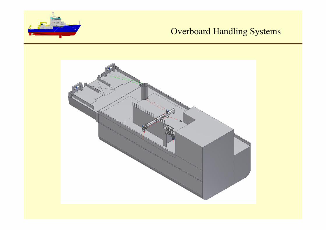
Overboard Handling Systems

Overboard Handling Systems

9
CTD Handling System

What is Bubble Sweepdown?
• Air bubbles originating at the surface caught in the vessel flow stream lines and swept along and under the hull
• Primary source is the ship’s bow wake but also natural wind/wave interactions (in higher sea states)
• Can cause significant sonar performance degradations
• Increases ambient noise as well as creating a barrier that can attenuate both outgoing and returning sonar signals
• Effects generally worse at higher sea states and higher speeds

Slide 11
Tools to Be Employed At Each Design Stage
• Concept Design
• Hull Features to Avoid Known Causes of Bubbles
• No Bulbous Bow; No Tunnel Thrusters
• Transducers Located in Gondola and Drop Keel
• The Most Effective Technique to Avoid Bubbles
• Preliminary Design
• CFD Analysis of Flow lines Around Hull and Sonar Appendages to Confirm That Flow Lines Originating at Stem Do Not Cross Transducer Faces
• Flow Origination Points Varied Below Even Keel DWL to Simulate Pitching
• Contract Design
• Physical Model Testing for Flow Visualization
• Yarn Tuft and Wet Paint “Smear” Tests
• Flow Testing Using Dye Injected at Ship Bow
• Flow Origination Points Varied Below Even Keel DWL to Simulate Pitching

Slide 12
Waterline at 0 Deg Pitch Waterline at SS2, 12 knots Pitch Waterline at SS4, 8 knots Pitch
Streamline Initiation Points
Streamline Initiation Points

Slide 13
Wave field at 12 knots
Wave field at 8 knots
Bubble Sweepdown CFD

Slide 14
View of Underhull Streamlines
Bubble Sweepdown CFD

Profile View of Underhull Streamlines
Slide 15
Even Keel Streamline
SS2, 12 Knot Streamline
Streamlines that interfere with gondola – well below pitched waterline
SS4, 8 Knot Streamline
Gondola
Drop Keels

Dye Injection Tube
Model Dye Testing Arrangement
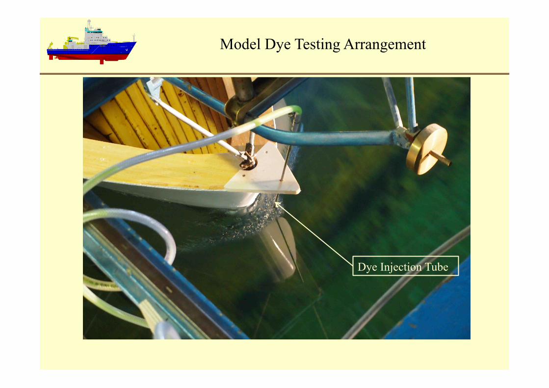
Dye Injection Tube
Model Dye Testing Arrangement

Streamline
Gondola
DWL
12 Knots, DWL Dye Injection Point
Stem Line
Drop Keels
Model Dye Testing Arrangement

Streamline
Gondola
DWL
12 Knots, Lowest Dye Injection Point
Drop Keels
Model Dye Testing Arrangement

Slide 20
AC-DC Propulsion Study

21
Radiated Noise Requirements

Why Have DC Motors Been Used?
• Only available choice for electric propulsion until ~ 15 years ago – AC low speed control difficult – AC development of high torque at low speed difficult
• DC technology was mature and modified to meet low structureborne noise requirements – Skewed slots – Increased number of poles – Special stacking of laminations – Low flux – Specially designed brushes and rigging – Resilient mounting of cooler fans – Other measures
25/05/11 Slide 22

Why Shift to AC Motors?
• DC motors have some disadvantages – Brushes require maintenance and replacement – Thyristor power converters introduce undesired electrical harmonics into
the electrical system (require harmonic filters unless a 24 or more pulse system is used)
– Large phase shifting transformers are required
• AC motor technology has matured significantly and is now the main choice for electric propulsion – Motors are smaller and lighter – Power conversion equipment is heavier than DC – Overall an AC system is lighter and usually less expensive – Saves space in the ship – Less maintenance overall
25/05/11 Slide 23

Why Have AC Motors Not Been Used in Quiet Ships?
• AC drives require two power conversions – AC to DC and DC back to AC which creates torque pulses in the
motor • Creates structureborne vibration • Creates unsteady forces on the propeller
– Introduction of pulse width modulation (PWM) and indirect power conversion reduces noise (active front end)
– Use of simpler induction motors with an active front end and a sine wave filter at the input to the motor show promise for quiet ships
25/05/11 Slide 24

Is ICES 209 or DNV Silent R Achievable with AC Propulsion?
• Based on existing vessel data and manufacturer predictions it appears possible that AC propulsion can support ICES 209 or Silent R
• Drive system must use an active front end and sine wave filter • Motors must meet a structureborne noise requirement • Motors must incorporate quieting technology:
25/05/11 Slide 25

Quiet AC Drive System
25/05/11 Slide 26
27
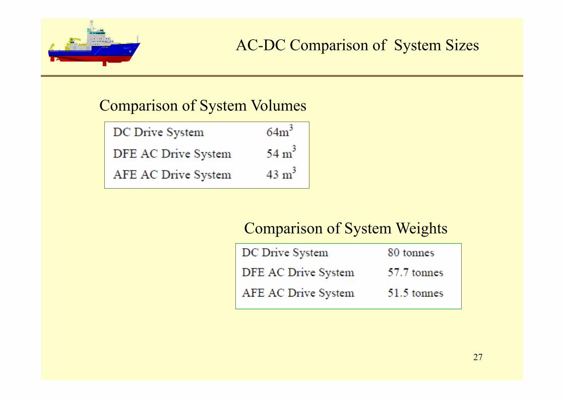
AC-DC Comparison of System Sizes
Comparison of System Volumes
Comparison of System Weights

28
AC-DC Comparison of Efficiency and Fuel Consumption

29
AC-DC Comparison
End