cs 356: computer network architectures lecture 15: dhcp
TRANSCRIPT

CS 356: Computer Network Architectures
Lecture 15: DHCP, NAT, IPv6, and IP tunnels
[PD] chapter 3.2.7, 3.2.9, 4.1.3, 4.3.3
Xiaowei [email protected]

Overview
• Miscellaneous topics
• Sample midterm released

BGP Scalability

Routing table scalability with Classful IP Addresses
• Fast growing routing table size• Classless inter-domain routing aims to address
this issue

CIDR hierarchical address allocation
• IP addresses are hierarchically allocated.• An ISP obtains an address block from a Regional Internet Registry• An ISP allocates a subdivision of the address block to an organization• An organization recursively allocates subdivision of its address block to its
networks• A host in a network obtains an address within the address block assigned to
the network
ISP128.0.0.0/8
128.1.0.0/16
Foo.com
128.2.0.0/16
Library CS
128.195.0.0/16
128.195.1.0/24 128.195.4.0/24
UniversityBar.com
128.195.4.150

Hierarchical address allocation
• ISP obtains an address block 128.0.0.0/8 à [128.0.0.0, 128.255.255.255]
• ISP allocates 128.195.0.0/16 ([128.195.0.0, 128.195.255.255]) to the university.
• University allocates 128.195.4.0/24 ([128.195.4.0, 128.195.4.255]) to the CS department’s network
• A host on the CS department’s network gets one IP address 128.195.4.150
128.0.0.0 128.255.255.255128.195.0.0 128.195.255.255
128.195.4.0 128.195.4.255 128.195.4.150

CIDR allows route aggregation
• ISP1 announces one address prefix 128.0.0.0./8 to ISP2
• ISP2 can use one routing entry to reach all networks connected to ISP1
ISP1128.0.0.0/8
128.1.0.0/16
Foo.com
128.2.0.0/16
Library CS
128.195.0.0/16
UniversityBar.com
IISP3
You can reach 128.0.0.0/8 via ISP1
128.0.0.0/8 ISP1

Multi-homing increases routing table size
Mutil-home.com
128.0.0.0/8204.0.0.0/8
204.1.0.0/16
ISP2 ISP1
You can reach 128.0.0.0/8And 204.1.0.0/16 via ISP1
ISP3
204.1.0.0/16 ISP1204.1.0.0/16128.0.0.0/8 ISP1
204.1.0.0/16 ISP2204.0.0.0/8 ISP2

Global routing tables continue to grow (1989-now)
Source: https://www.cidr-report.org
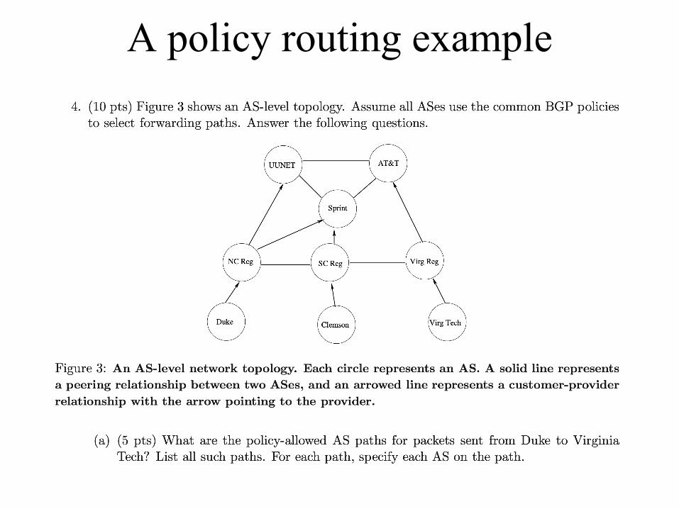
A policy routing example

Dynamic Host Configuration Protocol (DHCP)
Dynamic Assignment of IP addresses
• Dynamic assignment of IP addresses is desirable– IP addresses are assigned on-demand– Avoid manual IP configuration• Inconvenient, error prone• ifconfig
– Support mobile devices

DHCP• Dynamic Host Configuration Protocol (DHCP) – Designed in 1993– Supports temporary allocation (“leases”) of IP addresses– DHCP client can acquire all IP configuration parameters
• Default router, network mask, DNS resolver
• Sent as UDP packets
• A client-server protocol– Server port: 67– Client port: 68
• Most client-server protocols do not have unique client ports

DHCP Message Format
Number of Seconds
OpCode Hardware Type
Your IP address
Unused (in BOOTP)Flags (in DHCP)
Gateway IP address
Client IP address
Server IP address
Hardware AddressLength Hop Count
Server host name (64 bytes)
Client hardware address (16 bytes)
Boot file name (128 bytes)
Transaction ID
Options
(There are >100 different options)

DHCP• OpCode: 1 (Request), 2(Reply)
Note: DHCP message type is sent in an option
• Hardware Type: 1 (for Ethernet)• Hardware address length: 6 (for Ethernet)• Hop count: set to 0 by client• Transaction ID: Integer (used to match reply to response)• Seconds: number of seconds since the client started to boot
• Client IP address, Your IP address, server IP address, Gateway IP address, client hardware address, server host name, boot file name:client fills in the information that it has, leaves rest blank

DHCP Message Type
• Message type is sent as an option.
Value Message Type1 DHCPDISCOVER 2 DHCPOFFER 3 DHCPREQUEST 4 DHCPDECLINE 5 DHCPACK 6 DHCPNAK 7 DHCPRELEASE 8 DHCPINFORM

DHCP operations
Src: 0.0.0.0, 68Dest: 255.255.255.255, 67DHCPDISCOVERYYiaddr: 0.0.0.0Transaction ID: 654
Src:128.195.31.1, 67
DHCPOFFERYiaddr: 128.195.31.147Transaction ID: 654
Dest: 255.255.255.255, 68
Lifetime: 3600 secsServer ID: 128.195.31.1

DHCP operationsSrc: 0.0.0.0, 68Dest: 255.255.255.255, 67DHCPREQUESTYiaddr: 128.195.31.147Transaction ID: 655server ID: 128.195.31.1Lifetime: 3600 secs
Src:128.195.31.1, 67
DHCPACKYiaddr: 128.195.31.147Transaction ID: 655
Dest: 255.255.255.255, 68
Lifetime: 3600 secsServer ID: 128.195.31.1

More on DHCP operations• A client may receive DCHP offers from multiple servers
• The DHCPREQUEST message accepts offers from one server
• Other servers who receive this message considers it as a decline
• A client can use its address after receiving DHCPACK
• DHCP replies can be unicast, depending on implementation– Client hardware address as MAC destination– Yiaddr as IP destination

Scalability
• How many DHCP servers do we need?– Routers do not forward broadcast IP addresses– One per subnetwork! Too many
• Solution: relay agent– Configured with the DHCP server’s IP address– One relay agent per subnetwork– Unicast to the DHCP server

DHCP relay agent
DHCPDISCOVERGiaddr: 0
Src: 0.0.0.0., 68Dest: 255.255.255.255, 67
128.195.31.1 128.195.41.1
DHCPDISCOVERGiaddr: 128.195.41.1
Src: 0.0.0.0., 68Dest: 128.195.31.10, 67
DHCPOFFER
……
Giaddr: 128.195.41.1
Src: 128.195.31.10, 67Dest: 128.195.41.1, 67
DHCPOFFER
……
Giaddr: 128.195.41.1
Src: 128.195.41.1, 67Dest: 255.255.255.255, 68
128.195.31.10

Well-known client port
• Why does DHCP choose a well-known client port?
• A: For relay purpose. Otherwise, the relay agent has to remember the port of the original DHCP discovery message.

History of DHCP
• Three Protocols:– RARP (until 1985, no longer used)– BOOTP (1985-1993)– DHCP (since 1993)
• Only DHCP is widely used today

Network Address Translation

Network address translation• A fix to the IP
address depletion problem.– NAT is a router
function where IP addresses (and possibly port numbers) of IP datagrams are replaced at the boundary of a private network
• We’ll discuss another solution: IPv6
http://www.potaroo.net/tools/ipv4/index.html

Basic operation of NAT
• NAT device has address translation table
•H1
•private address: 10.0.1.2•public address: 128.143.71.21
•H5
•Private•network
•Internet
•Source •= 10.0.1.2•Destination •= 213.168.112.3
•Source •= 128.143.71.21•Destination •= 213.168.112.3
•public address: • 213.168.112.3•NAT•device
•Source •= 213.168.112.3•Destination •= 128.143.71.21
•Source •= 213.168.112.3•Destination •= 10.0.1.2
•Private•Address
•Public•Address
•10.0.1.2 •128.143.71.21

Private Network• Private IP network is an IP network that is not directly
connected to the Internet
• IP addresses in a private network can be assigned arbitrarily. – Not registered and not guaranteed to be globally unique– Public IP address are assigned via Internet registries
• Generally, private networks use addresses from the following experimental address ranges (non-routable addresses): – 10.0.0.0 – 10.255.255.255– 172.16.0.0 – 172.31.255.255– 192.168.0.0 – 192.168.255.255

Main uses of NAT
• Pooling of IP addresses
• Supporting migration between network service providers
• IP masquerading
• Load balancing of servers

Pooling of IP addresses• Scenario: Corporate network has many hosts but
only a small number of public IP addresses
• NAT solution:– Corporate network is managed with a private address space– NAT device manages a pool of public IP addresses
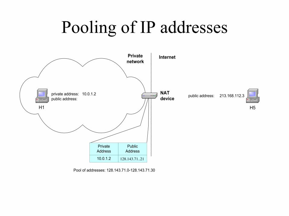
Pooling of IP addresses
H1
private address: 10.0.1.2public address:
H5
Privatenetwork
Internet
Source = 10.0.1.2Destination = 213.168.112.3
Source = 128.143.71.21Destination = 213.168.112.3
public address: 213.168.112.3NATdevice
PrivateAddress
PublicAddress
10.0.1.2
Pool of addresses: 128.143.71.0-128.143.71.30
128.143.71..21

Supporting migration between network service providers
• Scenario: a corporate network changes its ISP• change all IP addresses in the network?
• NAT solution:– Assign private addresses to the hosts of the corporate
network– NAT device has address translation entries which bind the
private address of a host to the public address. – Migration to a new network service provider merely
requires an update of the NAT device. The migration is not noticeable to the hosts on the network.

Supporting migration between network service providers

IP masquerading
• Also called: Network address and port translation (NAPT), port address translation (PAT).
• Scenario: Single public IP address is mapped to multiple hosts in a private network.
• NAT solution:– Assign private addresses to the hosts of the corporate
network– NAT device modifies the port numbers for outgoing traffic

IP masquerading
•H1
•private address: 10.0.1.2
•Private network
•Source •= 10.0.1.2•Source port •= 2001
•Source •= 128.143.71.21•Source port •= 2100
•NAT•device
•Private•Address
•Public•Address
•10.0.1.2/2001 •128.143.71.21/2100•10.0.1.3/3020 •128.143.71.21/4444
•H2
•private address: 10.0.1.3
•Source •= 10.0.1.3•Source port •= 3020
•Internet
•Source •= 128.143.71.21•Source port •= 4444
•128.143.71.21

Load balancing of servers• Scenario: Balance the load on a set of identical servers, which
are accessible from a single IP address– Used by many distributed service providers such as Google
• NAT solution:– Here, the servers are assigned private addresses – NAT device acts as a proxy for requests to the server from the public
network– The NAT device changes the destination IP address of arriving packets
to one of the private addresses for a server– A sensible strategy for balancing the load of the servers is to assign the
addresses of the servers in a round-robin fashion. • Or hashing
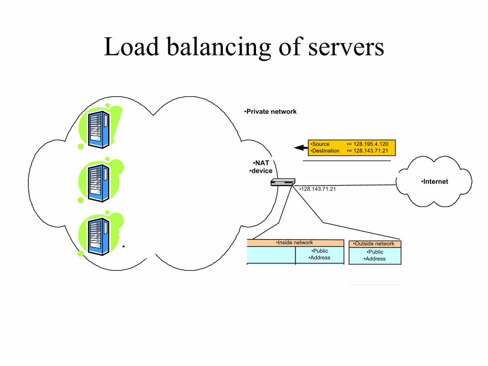
Load balancing of servers
•Private network
•Source •= 213.168.12.3•Destination •= 128.143.71.21
•NAT•device
•Public•Address
•10.0.1.2 •128.143.71.21
•Inside network
•10.0.1.4 •128.143.71.21
•Internet•128.143.71.21
•Public•Address
• 128.195.4.120
•Outside network
• 213.168.12.3
•Source •= 128.195.4.120•Destination •= 128.143.71.21
Source: 128.195.4.120
Dest: 10.0.1.2
Source: 213.168.12.3
Dest: 10.0.1.4

Concerns about NAT• Performance:–Modifying the IP header by changing the IP address
requires that NAT boxes recalculate the IP header checksum
–Modifying port number requires that NAT boxes recalculate TCP checksum
• Fragmentation– Care must be taken not to assign a fragment different IP
or port number

Concerns about NAT
• End-to-end connectivity:– NAT destroys universal end-to-end reachability of hosts on
the Internet. – A host in the public Internet often cannot initiate
communication to a host in a private network. – The problem is worse, when two hosts that are in a private
network need to communicate with each other.• Difficult to deploy peer-to-peer applications such as Skype

NAT and FTP
• Normal FTP operation• What problem will FTP run into if using
unmodified NAT?
•H1 •H2
public address:128.143.72.21
FTP client FTP server
PORT 128.143.72.21/1027
200 PORT command successful
public address:128.195.4.120
RETR myfile
150 Opening data connection
establish data connection

NAT and FTP
• NAT device with FTP support
H1
Private network
NATdevice
H2
private address: 10.0.1.3public address: 128.143.72.21
Internet
FTP client FTP server
PORT 10.0.1.3/1027 PORT 128.143.72.21/1027
200 PORT command successful200 PORT command successful
RETR myfile
establish data connection
RETR myfile
150 Opening data connection150 Opening data connection
establish data connection

NAT and FTP
• FTP in passive mode and NAT.
H1
Private network
NATdevice
H2
private address: 10.0.1.3public address: 128.143.72.21
Internet
FTP client FTP server
PASV PASV
Entering Passive Mode128.195.4.120/10001
Entering Passive Mode128.195.4.120/10001
public address:128.195.4.120
Establish data connection Establish data connection

Next Generation IP (IPv6)

Addressing• 128-bit addresses
– 2128
• "if the earth were made entirely out of 1 cubic millimetre grains of sand, then you could give a unique [IPv6] address to each grain in 300 million planets the size of the earth"
• http://en.wikipedia.org/wiki/IP_address
• Or, using a more earthly analogy:
• "The optimistic estimate would allow for 3,911,873,538,269,506,102 addresses per square meter of the surface of the planet Earth." "IP Next Generation Overview"
• R. Hinden, Communications of the ACM, Vol. 39, No. 6 (June 1996) pp 61 - 71, ISSN:0001-0782 http://portal.acm.org/citation.cfm?coll=GUIDE&dl=GUIDE&id=228517

IPv6 Addresses
• Classless addressing/routing (similar to CIDR)• Notation: x:x:x:x:x:x:x:x (x = 16-bit hex number)– contiguous 0s are compressed: 47CD::A456:0124– IPv6 compatible IPv4 address:
::FFFF:128.42.1.87

IPv6 addressing architecture
• RFC 4291• All addresses are assigned to interfaces, not
nodes

Types of IPv6 addresses
Address type Binary prefix IPv6 notation
Unspecified 00...0 (128 bits) ::/128
Loopback 00...1 (128 bits) ::1/128
Multicast 11111111 FF00::/8
Link-local unicast 1111111010 FE80::/10
Global unicast Everything else
Anycast Allocated from unicast space

Global Unicast Addresses
• For all unicast addresses, except those that start with the binary value 000, Interface IDs are required to be 64 bits long – Can be derived from 48-bit Ethernet address
Global routing prefixn bits
Subnet ID m bits
Interface ID 128-n-m bits (typically 64 bits)

IPv6 Header• 40-byte “base” header• Extension headers (fixed order, mostly fixed
length)– fragmentation– source routing– authentication and
security– other options

Autoconfiguration
• Link-local prefix + interface ID• Routers advertise global prefixes

IPv6 Anycast Addresses
• Assigned to more than one interface• All zero interface address• Allocated from the unicast address space• Ex: all root DNS servers
Subnet prefix (n bits) 0000000 (128 – n bits)
IP Tunnels

IP tunnels
• Tunnels– A technique used in many scenarios• VPN, IPv4-v6 transition, Mobile IP, Multicast, Non-IP
forwarding, IPsec

What is a tunnel
• A “pseudowire”, or a virtual point-to-point link• The head router encapsulates a packet in an outer
header destined to the tail router
12.3.0.1 18.5.0.1
10/8 20/8
10.0.0.120.0.0.1
10.0.0.120.0.0.1
12.3.0.118.5.0.1 10.0.0.1
20.0.0.1
0 1R1 R2

Virtual interface
• A router adds a tunnel header for packets sent to a virtual interface
NetworkNum nextHop
10/8 ether020/8 tun00/0 ether1

Tunnel applications
• Traversing a region of network with a different addressing format or with insufficient routing knowledge
• Building virtual private networks

Copyright © 2012, Elsevier Inc. All rights Reserved
Chapter 3
FIGURE 3.26 An example of virtual private networks: (a) two separate private networks; (b) two virtual private networks sharing common switches.

IPv4-v6 transition
IPv6R1 R2
IPv6 IPv4
IPv6IPv6IPv4 IPv6

Generic Routing Encapsulation (GRE)
• Defined in RFC 2784 and updated by RFC 2890