compsci 356: computer network architectures lecture 4: link layer: encoding, framing, and error...
TRANSCRIPT

CompSci 356: Computer Network Architectures
Lecture 4: Link layer: Encoding,
Framing, and Error Detection
Xiaowei Yang

Overview• Review
– Physical links
– Link/network performance metrics• Bandwidth / throughput
• Latency / delay
• Bandwidth * delay product
• Link layer functions– Encoding
– Framing
– Error detection
– Reliable transmission (if have time)

The simplest network is one link plus two nodes
Hi Alice…
?

Recap: Put bits on the wire
• Each node (e.g. a PC) connects to a network via a network adaptor.
• The adaptor delivers data between a node’s memory and the network.
• A device driver is the program running inside the node that manages the above task.
• At one end, a network adaptor encodes and modulates a bit into signals on a physical link.
• At the other end, a network adaptor reads the signals on a physical link and converts it back to a bit.

Different types of physical links
• Wired links– Copper
– Fiber optics
• Wireless links– Wifi, WiMax, Bluetooth, ZigBee, …

Commonly Used Physical Links
• Different links have different transmission ranges– Signal attenuation
• Cables– Connect computers in the same building
• Leased lines– Lease a dedicated line to connect far-away nodes from
telephone companies

Cables
• CAT-5: twisted pair
• Coaxial: thick and thin
• Fiber
10BASE2 cable, thin-net
200m10Base4, thick-net500m
CAT-5
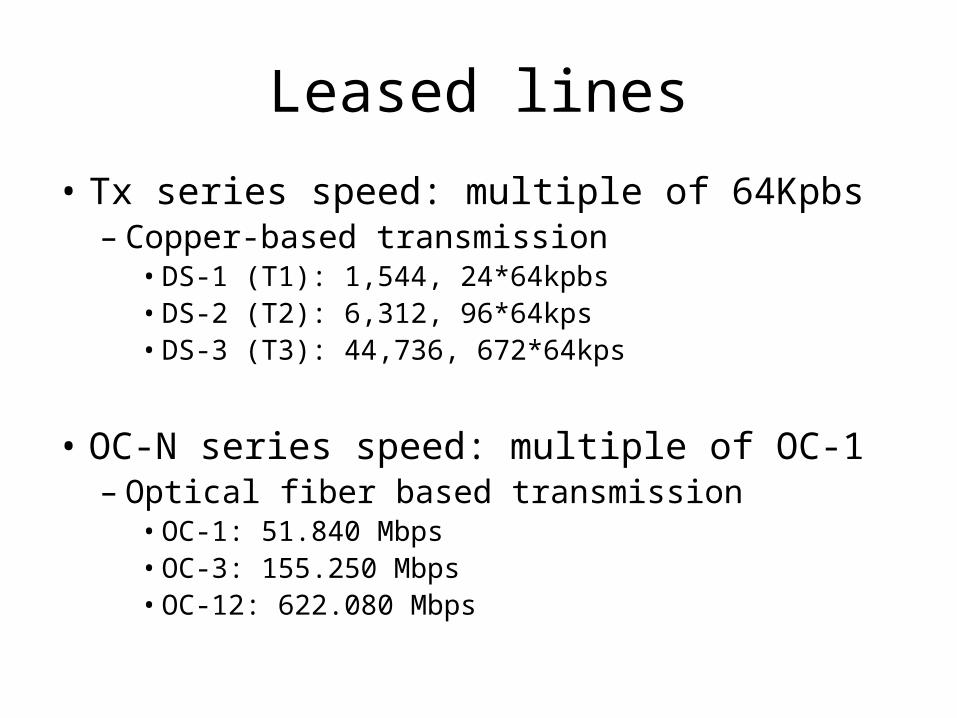
Leased lines
• Tx series speed: multiple of 64Kpbs– Copper-based transmission
• DS-1 (T1): 1,544, 24*64kpbs• DS-2 (T2): 6,312, 96*64kps• DS-3 (T3): 44,736, 672*64kps
• OC-N series speed: multiple of OC-1– Optical fiber based transmission
• OC-1: 51.840 Mbps• OC-3: 155.250 Mbps• OC-12: 622.080 Mbps

Last mile links
• Wired links– POTS: 28.8-56Kbps (Plain old telephone service)– ISDN: 64-128Kbps (Integrated Services Digital
Network)– xDSL: 128Kbps-100Mbps (over telephone lines)
• Digital Subscriber Line
– CATV: 1-40Mpbs (shared, over TV cables)
• Wireless links– Wifi, WiMax, Bluetooth, …

Central Office Subscriber premises
Local loopRuns on existing copper 18,000 feet at 1.544Mbps9,000 at 8.448 Mbps
ADSL
1.5-8.4Mpbs
16-640Kpbs
Central officeNbrhood optical
Network unitSubscriberpremises
OC links 13-55Mpbs
1000-4500 feet of copper
VDSL (Very high)Symmetric
xDSL wiring
Must install VDSLtransmission hardware

Wireless links• Wireless links transmit electromagnetic signals
through space– Used also by cellular networks, TV networks, satellite
networks etc.
• Shared media– Divided by frequency and space
• FCC determines who can use a spectrum in a geographic area, ie, “licensing”– Auction is used to determine the allocation– Expensive to become a cellular carrier
• Unlicensed spectrum– WiFi, Bluetooth, Infrared

Link Performance Metrics
• Propagation delay– How long it takes for one bit to travel from one end of a link to the other
end
• Bandwidth– How many bits a link can transmit in a unit time– Each bit is a pulse on the wire
• Must have certain width for the receiver to decode it

Latency and Throughput
• Latency of a message = Propagation + Transmit + Queue
• Propagation = Distance/SpeedOfWave
• Transmit = Size/Bandwidth
• Throughput = Size / Latency

Example
• 1Mbps, 100ms, 1MB data– Latency = 1MB/1Mbps + 100ms = 8.1s– Throughput = 1MB/8.1s ≈ 1Mbps
• 1Gbps, 100ms, 1MB data– Latency = 1MB/1Gbps + 100ms = 108ms– Throughput = 1MB/108ms = 74.1Mbps < 1Gbps
• Why?

Delay × Bandwidth Product
• Measures the volume of a pipe– The maximum number of bits can be in transit
through the pipe at any given instant
• To achieve high throughput, one should keep the pipe full

High speed versus low speed links

Link-layer functions
• Most functions are completed by adapters– Encoding
– Framing
– Error detection
– Reliable transmission (if have time)

Overview• Review
– Physical links
– Link/network performance metrics• Bandwidth / throughput
• Latency / delay
• Bandwidth * delay product
• Link layer functions– Encoding
– Framing
– Error detection
– Reliable transmission (if have time)

Encoding
• Encoding is the process to turn binary data (bits, 0s and 1s) into physical signals sent over a physical link
• Done by a piece of hardware on a network adaptor• High and low signals, ignore modulation• Simplest one: 1 to high, 0 to low

Non-return to zero• 1 to high, 0 to low
• Not good for decoding– Baseline wander
• Consecutive 1s or 0s cause the average signal level to drift– Receiver uses it to distinguish high/low signals
– Clock recovery• Receiver uses transition to 1s or 0s as clock boundaries to
synchronize clock

Solution 1: Nonreturn to zero inverted (NRZI) • A transition from current signal encodes 1• No transition encodes 0• Does it solve all problems?
– Not for consecutive 0s
NRZI

Solution 2: Manchester encoding• Clock XOR NRZ
– 1: high low; 0: low high
– Drawback: doubles the rate at which signals are sent• Baud rate: signal change rate• Bit rate = half of baud rate. 50% efficient
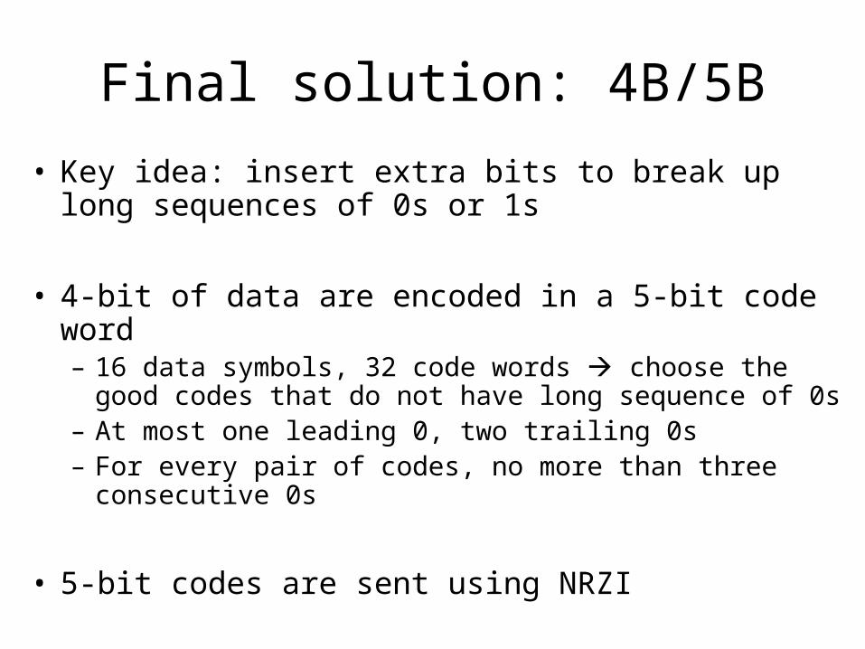
Final solution: 4B/5B
• Key idea: insert extra bits to break up long sequences of 0s or 1s
• 4-bit of data are encoded in a 5-bit code word– 16 data symbols, 32 code words choose the good codes that
do not have long sequence of 0s– At most one leading 0, two trailing 0s– For every pair of codes, no more than three consecutive 0s
• 5-bit codes are sent using NRZI
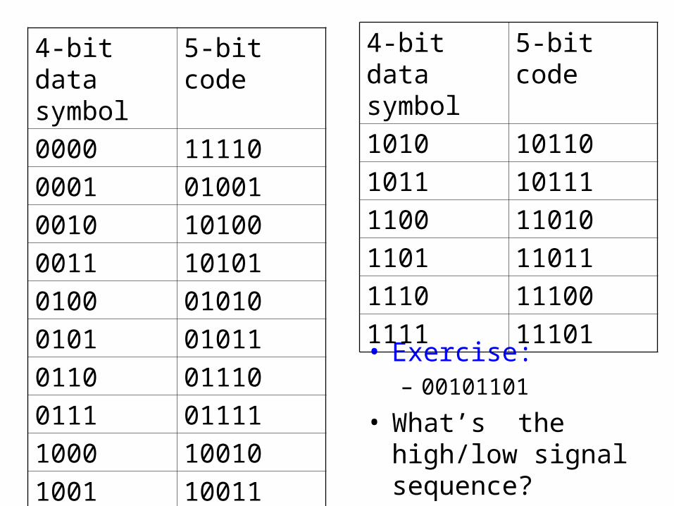
• Exercise:– 00101101
• What’s the high/low signal sequence?
4-bit data symbol
5-bit code
0000 11110
0001 01001
0010 10100
0011 10101
0100 01010
0101 01011
0110 01110
0111 01111
1000 10010
1001 10011
4-bit data symbol
5-bit code
1010 10110
1011 10111
1100 11010
1101 11011
1110 11100
1111 11101

Overview
• Link layer functions– Encoding
– Framing
– Error detection

Framing
• Now we’ve seen how to transmit bitstreams
• But nodes send blocks of data (frames)– A’s memory adaptor adaptor B’s memory
• An adaptor must determine the boundary of frames
Block of data

Variety of Framing Protocols• Framing: determining where the frame begins and
ends – Why is it an important task of an adaptor?
• Frames may belong to different apps• Need to decide when to deliver them
• Design choices– Byte-oriented protocols: the smallest unit of data is a byte
• Sentinel approach• Byte-counting approach
– Bit-oriented protocols– Clock-based framing

Byte-oriented protocols: the sentinel approach
• View each frame as a collection of bytes (characters)• Use special characters SYN, ETX to detect frame start and end• What if special characters appear in a data stream?
– Insert data link escape (DLE) characters– Character stuffing
•Transmitted from the leftmost bit•Binary Synchronous Communication (BISYNC) by IBM in late 60s

Point-to-Point Protocol (PPP)
• A data link protocol used to establish a direction connection between two nodes– Internet dialup access
• More recent, RFC 1661, 1994• Flag: 01111110; Address & Control: default• Protocol: demultiplexing
– IP, Link Control Protocol, …, • Checksum: two or four bytes• Link Control Protocol
– Set up and terminate the link– Negotiate other parameters such as maximum receive unit

Byte-oriented protocols: the byte counting approach
• Use a byte count field to detect the end of a frame.• The corruption of the count field may cause back-to-
back frame losses– A similar problem may occur in the sentinel approach.
• Corrupted ETX
•DDCMP by DECNET

Bit-oriented protocols
• View a frame as a collection of bits• 01111110 is the beginning and ending sequence• The sequence is also transmitted when the links are idle• Bit-stuffing for data
– Sender: inserts a 0 after every five consecutive 1’s– Receiver: after five consecutive 1’s,
• If the next bit is 0, removes it• If the next bit is 1
– If the next bit is 0 (i.e. the last 8 bits are 01111110), then frame ends– Else error; discard frame, wait for next 01111110 to receive
• Frames are of variable length, dependent on the data– Mainly because of stuffing
•High-level data link control (HDLC) protocol
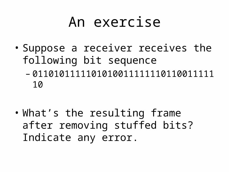
An exercise
• Suppose a receiver receives the following bit sequence– 011010111110101001111111011001111110
• What’s the resulting frame after removing stuffed bits? Indicate any error.

Clock-based Framing
• Synchronous Optical Network (SONET)– A complex protocol
• Each frame is 125 us long, 810bytes = 125 us * 51.84Mbps– 9 rows of 90 bytes each– First 3 bytes are overhead– First two bytes of each frame has a special pattern marking the start of a frame
• When the special pattern turns up in the right place enough times (every 810B), a receive concludes it’s in sync.
•STS-1/OC-1 frame
•51.840Mbps
•The slowest SONET link

Synchronized timeslots as placeholder
• Real frame data may float inside

Overview
• Link layer functions– Encoding
– Framing
– Error detection
Error detection
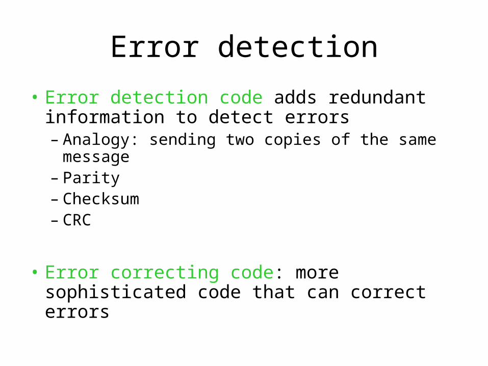
• Error detection code adds redundant information to detect errors– Analogy: sending two copies of the same message– Parity– Checksum– CRC
• Error correcting code: more sophisticated code that can correct errors

Two-dimensional parity
• Even parity bit– Make an even number of 1s in each row and column
• Detect all 1,2,3-bit errors, and most 4-bit errors
A sample frame of six bytes
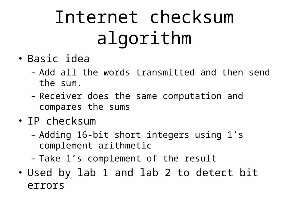
Internet checksum algorithm
• Basic idea– Add all the words transmitted and then send the sum.
– Receiver does the same computation and compares the sums
• IP checksum– Adding 16-bit short integers using 1’s complement
arithmetic
– Take 1’s complement of the result
• Used by lab 1 and lab 2 to detect bit errors

1’s complement
• -x is each bit of x inverted
• If there is a carry bit, add 1 to the sum
• Example: 4-bit integer– -3: 1100 (invert of 0011)
– -4: 1011 (invert of 0100)
– -3 + -4 = 0111 + 1 = 1000 (invert of 0111 (8))

IP checksum implementation
• uint16_t cksum (const void *_data, int len) { const uint8_t *data = _data; uint32_t sum;
for (sum = 0;len >= 2; data += 2, len -= 2) sum += data[0] << 8 | data[1]; if (len > 0) sum += data[0] << 8; while (sum > 0xffff) sum = (sum >> 16) + (sum & 0xffff); sum = htons (~sum); return sum ? sum : 0xffff;}

Remarks
• Can detect 1 bit error
• But not all two-bits– One increases the sum, and one decreases it
• Efficient for software implementation– Needs to be done for every packet inside a router!
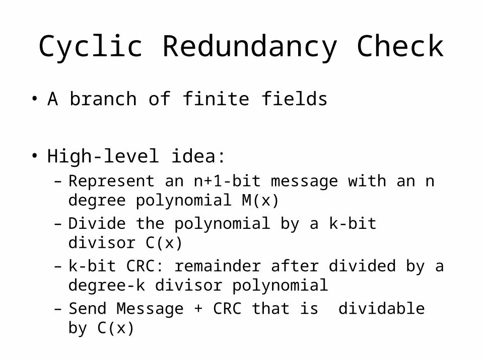
Cyclic Redundancy Check
• A branch of finite fields
• High-level idea:– Represent an n+1-bit message with an n degree polynomial
M(x)
– Divide the polynomial by a k-bit divisor C(x)
– k-bit CRC: remainder after divided by a degree-k divisor polynomial
– Send Message + CRC that is dividable by C(x)

Polynomial arithmetic modulo 2
– B(x) can be divided by C(x) if B(x) has higher degree
– B(x) can be divided once by C(x) if of same degree
– Remainder of B(x)/C(x) = B(x) – C(x)
– Substraction is done by XOR each pair of matching coefficients

CRC algorithm
1. Multiply M(x) by x^k. Add k zeros to Message. Call it T(x)
2. Divide T(x) by C(x) and find the remainder
3. Send P(x) = T(x) – remainder• Append remainder to T(x)
• P(x) dividable by C(x)

An example
• 8-bit msg– 10011010
• Divisor (3bit CRC)– 1101

How to choose a divisor
• Complicated
• Intuition: unlikely to be divided evenly by an error
• Corrupted msg is P(x) + E(x)
• If E(x) is single bit, then E(x) = xi
• If C(x) has the first and last term nonzero, then detects all single bit errors
• Find C(x) by looking it up in a book

Hardware implementation
• Very efficient: XOR operations
• 0 to k-1 registers (k-bit shift registers)
• If nth (n < k) term is not zero, places an XOR gate
• x3 + x2 + 1
Summary
• Link performance metrics reviewed
• Link layer functions– Encoding– Framing– Error detection
• Parity, Checksum, CRC
• Next lecture– Reliable transmission– Multi-access link