cryogenicoxygenjetresponse totransverseacousticexcitation...
TRANSCRIPT
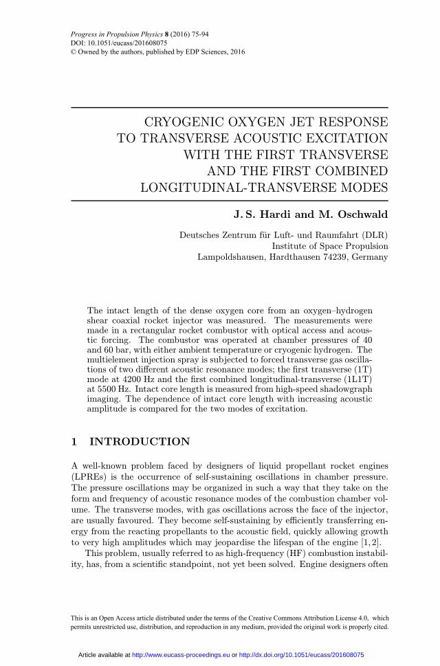
CRYOGENIC OXYGEN JET RESPONSETO TRANSVERSE ACOUSTIC EXCITATION
WITH THE FIRST TRANSVERSEAND THE FIRST COMBINED
LONGITUDINAL-TRANSVERSE MODES
J. S. Hardi and M. Oschwald
Deutsches Zentrum f�ur Luft- und Raumfahrt (DLR)Institute of Space Propulsion
Lampoldshausen, Hardthausen 74239, Germany
The intact length of the dense oxygen core from an oxygen�hydrogenshear coaxial rocket injector was measured. The measurements weremade in a rectangular rocket combustor with optical access and acous-tic forcing. The combustor was operated at chamber pressures of 40and 60 bar, with either ambient temperature or cryogenic hydrogen. Themultielement injection spray is subjected to forced transverse gas oscilla-tions of two di¨erent acoustic resonance modes; the ¦rst transverse (1T)mode at 4200 Hz and the ¦rst combined longitudinal-transverse (1L1T)at 5500 Hz. Intact core length is measured from high-speed shadowgraphimaging. The dependence of intact core length with increasing acousticamplitude is compared for the two modes of excitation.
1 INTRODUCTION
A well-known problem faced by designers of liquid propellant rocket engines(LPREs) is the occurrence of self-sustaining oscillations in chamber pressure.The pressure oscillations may be organized in such a way that they take on theform and frequency of acoustic resonance modes of the combustion chamber vol-ume. The transverse modes, with gas oscillations across the face of the injector,are usually favoured. They become self-sustaining by e©ciently transferring en-ergy from the reacting propellants to the acoustic ¦eld, quickly allowing growthto very high amplitudes which may jeopardise the lifespan of the engine [1, 2].This problem, usually referred to as high-frequency (HF) combustion instabil-
ity, has, from a scienti¦c standpoint, not yet been solved. Engine designers often
Progress in Propulsion Physics 8 (2016) 75-94 DOI: 10.1051/eucass/201608075 © Owned by the authors, published by EDP Sciences, 2016
This is an Open Access article distributed under the terms of the Creative Commons Attribution License 4.0, which permits unrestricted use, distribution, and reproduction in any medium, provided the original work is properly cited.
Article available at http://www.eucass-proceedings.eu or http://dx.doi.org/10.1051/eucass/201608075
PROGRESS IN PROPULSION PHYSICS
employ passive damping measures to extract acoustic energy from the combus-tion chamber and, thereby, suppress HF instability. Such measures allow enginesto §y; however, this engineering approach to the problem has proven its fallibility.In Europe, for example, an Ariane 1 launcher was famously struck by an instanceof HF instability in one of its Viking engines. Episodes of HF instability havealso occurred during testing of the cryogenic, upper-stage HM7B engine for theAriane 4 vehicle [3], which uses the liquid oxygen/hydrogen (LOx/H2) propel-lant combination. At subscale, a research combustor at DLR Lampoldshausenknown as L42-BKD experiences HF instabilities which initiate spontaneouslyunder certain operating conditions [4,5]. The mechanisms by which energy fromcombustion is transferred to the acoustic ¦eld and allow these instabilities be-come self-sustaining need to be better understood in order to reliably preventtheir occurrence.In LPREs running with LOx/H2, the use of shear-coaxial type elements in
the injector assembly is common. Each element injects a central jet of densecryogenic LOx and a surrounding high-speed jet of supercritical H2. The dense¢core£ of injected LOx penetrates into the combustion chamber and is broken upand atomized by the shear forces exerted by the surrounding H2 §ow. Numerousresearchers have investigated the breakup behavior experimentally using backlit-shadowgraph imaging techniques [6�8]. Others have characterized the breakupbehaviors into regimes based on injection parameters [9�11].The distance the LOx core penetrates into the combustion chamber before
being atomized is thought to be important to the coupling of acoustic distur-bances with combustion. A measure of this penetration distance is often takenas the axial length of the intact part of the LOx core, from injection to the ¦rstcomplete break in the core. Woodward et al. [12], Yang et al. [13], and Lockeet al. [14], for example, have made systematic measurements of the intact corelength in lab-scale, shear-coaxial, single-injector combustors burning LOx/H2.Of particular relevance to acoustic coupling is the behavior of the LOx core
in response to conditions of HF instabilities. Under cold-§ow conditions, HFinstability has been simulated by forcing a transverse acoustic ¦eld using loudspeakers. Miesse showed simple jets of water contracting when subjected to oscil-lating transverse acoustic velocity [15]. A research group at Air Force ResearchLaboratory in the U.S. has conducted extensive testing with cryogenic liquidnitrogen/gaseous nitrogen as LOx/H2 simulants, subjected to acoustic forcing.Core length reduction in response to the transverse acoustic velocity was foundto be dependent on chamber pressure as well as injection parameters such asgas/liquid velocity ratio (VR) and momentum §ux ratio (J) [16�18].In France and Germany, two-dimensional (2D) combustor designs with op-
tical access have allowed the response of reacting injection sprays to be stud-ied. Under hot-¦re conditions, modulating the exhaust nozzle §ow rate us-ing a toothed wheel, or siren, has proven to be an e¨ective means of excit-ing transverse acoustic resonance modes of the combustion chamber. Rey et
76

LIQUID AND ELECTRIC SPACE PROPULSION
al. [19], Richecoeur et al. [20,21], and M‚ery et al. [22] have studied LOx/H2 andLOx/CH4 response from multiple shear-coaxial injection elements. Valuable ob-servations were made from high-speed imaging of both the §ame luminosity andthe LOx core. The §ame was imaged by capturing ¦ltered chemiluminescentemission from the hydroxyl radical (OH∗), and the LOx core was visualized us-ing a backlit shadowgraph technique. No measurements of the intact length ofthe LOx core were presented. Sliphorst applied the same imaging techniques toa single LOx/CH4 injector and made systematic core length measurements [23].However, external acoustic forcing was not found to have a measurable in§uenceon the core length, which was attributed to the relatively low acoustic ampli-tudes.Measurements of the intact core length with increasing transverse acoustic
amplitude were presented by Hardi et al. [24,25]. The measurements were madein a 2D multielement LOx/H2 combustor with optical access and siren forcing,known as ¢BKH.£ High-speed images show signi¦cant reduction in core lengthduring excitation of the 1T mode of the combustion chamber. The core lengthis found to be dependent on the amplitude of the oscillating transverse acoustic§ow, with a core length reduction of up to 75% for amplitudes approaching thoseof naturally occurring HF combustion instabilities. Furthermore, a change in thenature of the core breakup and atomization mechanism was observed.These previous studies with BKH were made using excitation of the 1T mode,
around 4200 Hz. This is close to the 1T frequency in real, upper-stage en-gines. BKH was deliberately designed with this 1T-mode trait so as to result inspray-acoustic interaction at representative time scales. However, the aforemen-tioned L42-BKD combustor experiences spontaneous instabilities with 1T-modefrequencies above 10 kHz. Therefore, the current paper aims to explore thein§uence of excitation frequency on the core length response.Core length measurements from BKH during 1T-mode excitation will be
compared with those during excitation of the 1L1T mode. The 1L1T mode alsoproduces strong transverse acoustic velocity oscillations at the injector, yet hasa resonance frequency at least 1000 Hz higher. BKH operated at conditions thatare representative of real engines, which is intended to maximize the relevance ofthe results in understanding the coupling mechanisms, of full-scale combustioninstabilities.
2 EXPERIMENTAL METHOD
2.1 Combustor
Testing was conducted using the BKH combustor at the European Researchand Technology Test Facility P8 for cryogenic rocket engines at DLR Lam-
77

PROGRESS IN PROPULSION PHYSICS
Figure 1 Conceptual illustration of BKH (a) and a photograph taken during opticaltesting (b)
poldshausen. BKH has a rectangular cross section to ¦x the excited acousticresonance frequencies and mode structures and optical access windows for appli-cation of high-speed imaging. The injector consists of ¦ve shear-coaxial elementsarranged in a pattern which provides a representative environment for the cen-tral element, surrounded on all sides by other elements. Figure 1 shows BKHillustrated conceptually and photographed during testing with the optical accesswindow clearly visible.
2.2 Diagnostics
BKH uses a suite of conventional, low-frequency diagnostics to specify the op-erating conditions; §uid temperatures, pressures, and §ow rates. A set of sixhigh-frequency Kistler pressure transducers are §ush-mounted in the upper andlower combustion chamber walls. These transducers are sampled at 100 kHzand are used for characterizing the acoustic ¦eld. Optical access windows pro-vide a viewing area measuring 50 mm high and 100 mm long, with one sidealigned with the injection plane and the height su©cient to view the entire ¦ve-element injector. The setup of high-speed cameras is illustrated schematically inFig. 2.Backlit shadowgraph images are recorded with a Photron Fastcam SA5 using
an RG 850 long pass ¦lter to minimize §ame luminosity. Di¨erent camera set-
78

LIQUID AND ELECTRIC SPACE PROPULSION
Figure 2 Experimental setup for high-speed optical imaging
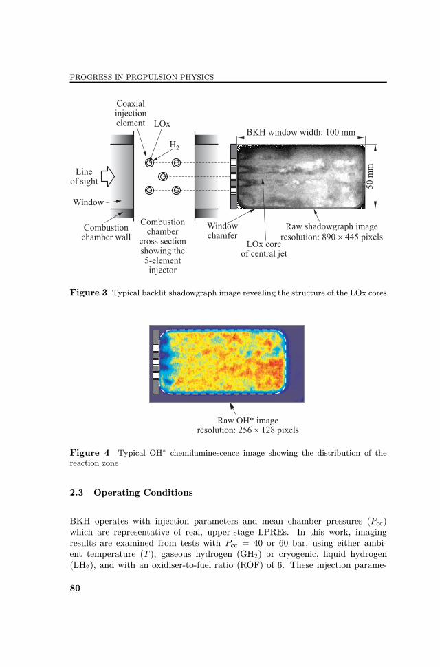
tings were used for di¨erent tests. Some of the tests were recorded with a framerate of 7000 fps, shutter speed 50 µs, and pixel resolution 890× 445, while theothers had 20,000 fps, shutter speed 33 µs, and resolution 690× 345. The ¦rstset of camera settings results in a sensing resolution of 0.11 mm2 per pixel. Thevelocity of LOx at the point of injection is around 12 m/s, resulting in a §owdisplacement of approximately 5 pixels (∼ 0.6 mm) during exposure time. Thesecond camera setting gives a sensing resolution of 0.14 mm2 per pixel, resultingin §ow displacements of around 3 pixels (∼ 0.4 mm) during image exposure.This means that the shadowgraph images from both tests may su¨er from blur-ring in some locations. An example of an instantaneous shadowgraph image isshown in Fig. 3.
A dichroic mirror allows a second high-speed camera to simultaneously recordOH∗ chemiluminescence. For this purpose, a Photron Fastcam-ultima APX-i2intensi¦ed camera with a ¦lter of pass-bandwidth 310±5 nm was used to recordimages with a frame rate of 24,000 fps and resolution of 256 × 128 pixels. Anexample of an instantaneous recorded image, presented in false color, is shownin Fig. 4. Such OH∗ emission imaging is taken to indicate the distribution of thereaction zone of the §ame.
79
PROGRESS IN PROPULSION PHYSICS
Figure 3 Typical backlit shadowgraph image revealing the structure of the LOx cores
Figure 4 Typical OH∗ chemiluminescence image showing the distribution of thereaction zone
2.3 Operating Conditions
BKH operates with injection parameters and mean chamber pressures (Pcc)which are representative of real, upper-stage LPREs. In this work, imagingresults are examined from tests with Pcc = 40 or 60 bar, using either ambi-ent temperature (T ), gaseous hydrogen (GH2) or cryogenic, liquid hydrogen(LH2), and with an oxidiser-to-fuel ratio (ROF) of 6. These injection parame-
80

LIQUID AND ELECTRIC SPACE PROPULSION
Table 1 Operating conditions
40 bar 60 barLH2 GH2 LH2
A B A B C A B
Pcc, bar 43.5 43.5 59.7 60.3 60.5 61.3 60.3ROF 6.0 6.0 6.0 6.0 6.0 6.0 6.0TH, K 75 62 281 278 288 64 62TO, K 132 132 124 128 123 127 126‘m, g/s 112 112 132 132 132 140 141uO, m/s 11 11 12 12 12 13 13uH, m/s 118 90 423 405 422 84 80VR 11 8.1 35 33 35 6.4 6.2J 1.9 1.4 6.3 5.7 6.2 1.1 1.1ReO 4.1 · 105 4.1 · 105 4.1 · 105 4.3 · 105 4.0 · 105 4.6 · 105 4.5 · 105
WeH 1.1 · 105 7.7 · 105 8.4 · 105 7.8 · 105 8.3 · 105 1.3 · 105 1.2 · 105
ters corresponding to each operating condition are summarized in Table 1. Otherparameters provided are per-element total mass §ow rate, ‘m, and injection ve-locity, u, where the subscripts O and H refer to oxygen and hydrogen, respec-tively. Nondimensional numbers provided are: hydrogen-to-oxygen velocity ra-tio, VR = uH/uO; momentum §ux ratio, J = (ρu
2)H/(ρu2)O; oxygen Reynolds
number, ReO = (ρuD/µ)O where D is the oxygen injector outlet diameter; andhydrogen Weber number, WeH = ρH(uH − uO)
2D/σO. Results from multipletests running similar conditions are distinguished by the designator A, B, or C.
2.4 Acoustic Excitation
BKH has a main nozzle at the end of the combustion chamber, as well as a sec-ondary nozzle in the upper wall (see Fig. 1). The exhaust §ow through thesecondary nozzle is modulated with a siren to excite acoustic resonances insidethe combustion chamber. The frequency of acoustic excitation is determined bycontrolling the rotational speed of the siren wheel. By linearly increasing therotational speed, the excitation frequency is ramped through a desired rangebetween 0 and 6000 Hz over the course of a 40- to 70-second test ¦ring. The 1Tresonance mode of the combustion chamber volume is excited as the excitationfrequency passes through approximately 4200 Hz. The 1L1T mode is excited ataround 5500 Hz.The structures of the 1T and 1L1T modes, obtained from a numerical modal
analysis, are given in Fig. 5. Acoustic pressure distributions are given on theleft-hand side, and the corresponding acoustic particle velocity vector ¦eld on
81

PROGRESS IN PROPULSION PHYSICS
Figure 5 Acoustic mode shapes of the 1T (a) and 1L1T (b) resonance modes in BKH,showing the pressure distribution (left) and velocity distribution (right). The upperrow of each group is at the start of an acoustic cycle and the lower row is one-quarterof a cycle later
82
LIQUID AND ELECTRIC SPACE PROPULSION
the right. The 1T mode (Fig. 5a) has a pressure node in the near-injector regionwhich means that exciting this mode results in high amplitudes of oscillatingacoustic gas motion transverse to the injection axis of the §ames. The 1L1Tmode (Fig. 5b) has a similar acoustic ¦eld distribution to the 1T mode at thelocation of the injector, also resulting in transverse oscillating gas §ow acrossthe injector face. A detailed study of the acoustic characteristics of BKH waspresented by Hardi et al. [26].Measurements of acoustic amplitude are taken from the dynamic pressure
transducer located in the lower wall of the chamber, nearest to the injector face,as indicated in Fig. 1. This sensor is chosen as it is located in a pressure antin-ode for both the 1T and 1L1T modes. High-frequency transducer signals areprocessed in the following way to obtain a time-dependent estimate of ampli-tude. First, the signal is high-pass ¦ltered to retain only acoustic resonancecontent above 2800 Hz. A Butterworth ¦lter was used, employing the ¦lt¦ltcommand in Matlab to prevent any phase shift of the output signal. A slidingroot-mean-square (RMS) calculation is performed on the ¦ltered signal, witha mean-window length of 121 samples and 50 percent overlap. Finally, pressureamplitude p′ is obtained by multiplying the RMS value by the square-root of 2.From p′, the magnitude of acoustic velocity (u′) at the nodal line is estimatedusing u′ = (cbulk/γ)(p
′/Pcc) where cbulk is the mean sound speed of the bulkgas mixture in the combustion chamber volume, and γ is the ratio of speci¦cheats.Excitation of the 1T and 1L1T resonance modes achieves acoustic pressure
amplitudes (p′) of up to 9% of Pcc (18% peak to peak), as compared to thechamber background noise during o¨-resonance periods of p′/Pcc ∼ 0.9%. Tra-ditionally, an LPRE is considered to experience HF instability when acousticoscillations reach amplitudes greater than 5% of Pcc (10% peak to peak) [27].
2.5 Liquid Oxygen Core Measurements
A typical BKH test sequence involves running the combustor to a steady-stateoperating condition and then accelerating the siren through a range of excitationfrequencies so as to meet and excite several acoustic modes of interest. Thehigh-speed cameras are triggered to record for 1- to 4-second durations, as theexcitation frequency approaches and passes through peak resonance of the 1Tand 1L1T modes.Sample periods of 5-millisecond duration were selected for various p′ levels
throughout this recording time. Samples were chosen from periods where §uctu-ations in p′ were minimal. Sampled image sequences consist of 35 and 100 framesfor the 7,000 and 20,000 fps recordings, respectively. Although the excitationfrequency is continuously increased at 166 Hz/s, over a 5-millisecond sampleperiod it can be considered quasi-steady.
83

PROGRESS IN PROPULSION PHYSICS
Figure 6 Example LOx core measurement, showing the contrast-enhanced image (a)and the manually identi¦ed end-point location overlaid on the raw image (b)
Flow ¦eld turbulence, as well as insu©cient contrast in the raw shadowgraphimages, prohibited successful implementation of an automated routine to detectand trace the intact LOx core. Instead, frame-by-frame identi¦cation of theend point of the intact core was performed manually. The images were ¦rstprocessed to enhance contrast gradients and reduce noise to aid the operatorin identifying the core end point. Figure 6 shows an example frame where theend-point location has been identi¦ed in the raw image with the assistance ofthe contrast-enhanced image.
3 RESULTS
3.1 Without Acoustic Excitation
First, the qualitative character of the shadowgraph image in Fig. 3 is considered,taken from the 60-bar GH2 test A. As this image was taken during o¨-resonanceexcitation with very low acoustic amplitudes, it is considered to represent thenatural behavior of the injected spray §ame. The dense LOx core of the centralinjection jet and those of the nearest outer (upper and lower) elements are clearlyvisible. They are identi¦able by the light shade of grey which masks the surface ofthe dense LOx structures. This shade of grey is near-infrared emission from hotcombustion products (H2O) forming in the thin shear layer between the surfaceof the LOx core and the surrounding H2 where primary mixing and reaction takesplace. The presence of infrared emission in the image is the result of the longerexposure time required to compensate for the lower intensity of a continuousbacklighting source. A similar e¨ect of this compromise was experienced byLocke et al. [14].While the outer LOx jets de§ect outwards somewhat, the central LOx jet
appears to continue more or less axially, as would be expected inside a real engine.The outer four injectors appear to have served their somewhat sacri¦cial purpose
84

LIQUID AND ELECTRIC SPACE PROPULSION
of providing a representative environment for the central injector. Dynamicbehavior of the central LOx core is observed in the high-speed image sequences.The central core penetrates a distance of approximately 13L/D into the chamberbefore beginning to breakup, where L is the intact core length and D is thediameter of the LOx injector ¡ 3.5 mm. The breakup mechanism is one ofsuccessive detachments of large, dense oxygen structures which become entrainedin the axial mean §ow. A detailed description of this natural shedding behavior,as well as example image sequences, can be found in [24, 25].
3.2 With Acoustic Excitation
Figure 7 shows example frames during 1T-mode excitation in 60-bar GH2 test C.Here, the central LOx core length is greatly reduced compared to its naturalstate, now only extending around 7L/D downstream of injection. The core isno longer given the opportunity to develop downstream because each pass ofthe transverse acoustic wave strips material from its surface. The core breakupmechanism has changed from its natural axial shedding mode to the one ofstripping and entrainment in the oscillating transverse §ow. Again, this behavioris described in more detail in [24, 25].
Cold §ow experiments [28] and three-dimensional numerical modeling [29�31]of jet-acoustic interaction have revealed further details of the core response. Thejet is observed to §atten into a sheet in the plane perpendicular to the impingingacoustic wave. This explains the §attening tapered form of the intact part of theLOx core when viewed from the side. This deformation results from the meanpressure gradient distribution which develops around the jet circumference whenexposed to a continuously oscillating gas §ow. Viewing this §attening fromabove (or the wave impingement direction) is currently only possible in cold§ow experiments and numerical simulations since in hot-¦re experiments, theinteraction has so far only been observed from the side.
Shortening of the LOx cores is accompanied by a retraction of the §ametowards the injection plane. The instantaneous OH∗ images in Fig. 7 (lower
Figure 7 Example shadowgraph and OH∗ image sequence during 1T-mode excitation
85
PROGRESS IN PROPULSION PHYSICS
row) shows that the reaction zone is no longer well distributed as the LOx coretravels downstream; rather, there are compact regions of high emission intensityas all combustion is taking place in a space approximately half the length of thewindow (50 mm). Core shortening and corresponding change in §ame structureto a more compact, intense form has also been observed with LOx/CH4 [20�22].This demonstrates the importance of characterizing the response of the LOxcores to transverse acoustic oscillations, since redistribution of heat release inthe chamber will a¨ect the coupling mechanism driving HF instability.
3.3 Comparison of Response to the First Transverseand the First Combined Longitudinal-Transverse Modes
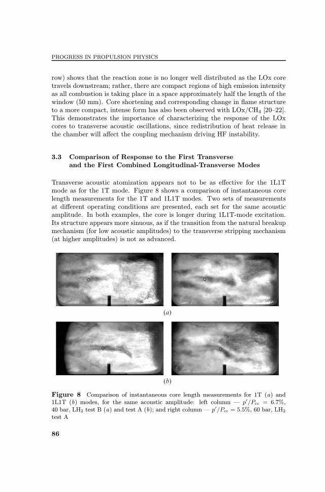
Transverse acoustic atomization appears not to be as e¨ective for the 1L1Tmode as for the 1T mode. Figure 8 shows a comparison of instantaneous corelength measurements for the 1T and 1L1T modes. Two sets of measurementsat di¨erent operating conditions are presented, each set for the same acousticamplitude. In both examples, the core is longer during 1L1T-mode excitation.Its structure appears more sinuous, as if the transition from the natural breakupmechanism (for low acoustic amplitudes) to the transverse stripping mechanism(at higher amplitudes) is not as advanced.
Figure 8 Comparison of instantaneous core length measurements for 1T (a) and1L1T (b) modes, for the same acoustic amplitude: left column ¡ p′/Pcc = 6.7%,40 bar, LH2 test B (a) and test A (b); and right column ¡ p′/Pcc = 5.5%, 60 bar, LH2test A
86

LIQUID AND ELECTRIC SPACE PROPULSION
3.4 Intact Core Length
Systematic measurements of intact core length were made during 1L1T-mode ex-citation, for various levels of acoustic excitation amplitude. These are presentedhere for comparison with the previous measurements made by the authors [24,25]under 1T-mode excitation. Table 1 lists the complete range of operating condi-tions covered for all 1T and 1L1T measurements.Figure 9 presents all core length measurements with increasing acoustic am-
plitude for tests with 60-bar chamber pressure. A trend line is provided for testswith GH2; it is not a ¦t to the data, but arbitrarily drawn and provided merelyto assist the eye in orienting the many measurement points. Filled symbols areused for 1L1T excitation. These points consistently lie above those for 1T exci-tation, meaning the core length was greater for the same acoustic amplitude, butunder a 1L1T-mode distribution and frequency. A second trend line, convergingon the same natural core length, is provided for orientation with the GH2 1L1Tset of points.Figure 10 presents measurements for 40-bar chamber pressure. Here, the
di¨erence between 1T and 1L1T excitations is also clearly evident. Trend linesare again provided for orientation, although the fewer number of measurementpoints available render their placement even less meaningful. They do, however,appear to converge on a longer natural core length than for the tests at 60 bar.
Figure 9 Intact core length measurements under 1T- (empty signs) and 1L1T-mode(¦lled signs) excitations in tests with Pcc = 60 bar: 1 ¡GH2, test A; 2 ¡GH2, test B;3 ¡ GH2, test C; 4 ¡ LH2, test A; 5 ¡ LH2, test B; and dashed and dotted lines ¡trend lines for all GH2 tests with 1T- and 1L1T-mode excitations, respectively
87

PROGRESS IN PROPULSION PHYSICS
Figure 10 Intact core length measurements under 1T- (empty signs) and 1L1T-mode(¦lled signs) excitations in tests with Pcc = 40 bar, LH2: 1 ¡ test A; 2 ¡ test B; anddashed and dotted lines ¡ trend lines for tests with 1T- and 1L1T-mode excitations,respectively
In both plots, the vertical error bars re§ect §uctuation in core length due tothe natural breakup mechanism, with axial growth and detachment. The notice-able reduction in error bar length with increasing acoustic amplitude re§ects thetransition from this natural breakup to the transverse stripping mechanism.Scatter in the measurements is due to natural turbulence and bending of
the long sinuous core. Bending of the core occasionally gives an arti¦cially shortlength measurement. Using the integrated length of the core center instead of endpoint location may reduce the in§uence of this behavior. However, as discussedpreviously, the automated core detection and tracing routine was unreliable.
4 DISCUSSION
Intact core length results show consistently longer cores for 1L1T-mode exci-tation. The acoustic ¦eld distribution for the 1L1T mode may account for itslesser in§uence. The 1T mode has a near uniform acoustic velocity ¦eld alongthe main chamber axis, corresponding to its pressure nodal line. By nature, the1L1T mode has a vertical nodal line approximately half way along the chamberaxis. This means the amplitude of oscillating acoustic velocity, u′, changes inthe chamber axial direction. From a velocity antinode at the injection plane, it
88

LIQUID AND ELECTRIC SPACE PROPULSION
decreases to zero at the vertical nodal line, then increases again (with opposingphase) approaching the main nozzle end of the chamber. Figure 11 compares thepro¦les of the transverse (vertical) component of u′ along the chamber centralaxis for the 1T and 1L1T modes. The velocity amplitude pro¦les were extractedfrom the numerical modal analysis in Fig. 5.The ¦rst 100 mm of the transverse velocity pro¦les in Fig. 11 are compared
more closely, as this is the region where most jet�acoustic interaction occurs,and where LOx core measurements can still be made. By the end of the opticalwindow, 100 mm downstream, u′ is practically zero for the 1L1T mode, while
Figure 11 Transverse velocity amplitude pro¦les along the chamber central axis forthe 1T (1) and 1L1T (2) modes (a), and the modal velocity distributions from whichthey are extracted: (b) 1T mode and (c) 1L1T mode
89

PROGRESS IN PROPULSION PHYSICS
the 1T mode is still almost at full strength. The mean value of transverse u′
from 0 to 100 mm for the 1L1T mode is 40% less than that of the 1T mode.
Additionally, the di¨erent time scales of jet�acoustic interaction may con-tribute to the di¨erence in 1T and 1L1T modes response. The time scale ofacoustic interaction with a jet is often compared to the convective time scaleusing the Strouhal number (St). Preferred modes of interaction for round jetsusually occur in the St range 0.2 to 0.4 [32, 33]. This has been demonstrated,for example, with unsteady Reynolds-averaged Navier�Stokes simulations of ve-locity oscillations on a cryogenic nitrogen jet [29]. The peak response, with themost shortening, was for St values from 0.2 to 0.3, above which the jet lengthincreased again. Schmitt et al. [34] compared St values for unexcited and ex-cited cryogenic nitrogen jets. Natural jet instability frequencies were measuredfrom large-eddy simulations, and the corresponding St values compared to thosede¦ned by the acoustic forcing in an accompanying experiment. The greater thedi¨erence between the natural and excited St values, the lower the level of jetresponse, both in experiment and simulation.
Here, it is instructive to consider the time scales of jet-acoustic interactionin BKH by comparing St values for 1T- and 1L1T-mode excitations. ExcitedStrouhal numbers can be calculated using the mean excitation frequency, fex,applied during high-speed imaging for the core length measurements in thiswork. Excited St values are given by St1Tex = f1Tex D/uO for 1T-mode excita-tion, or St1L1Tex = f1L1Tex D/uO for the 1L1T mode. Results are summarized inTable 2. All Stex for the BKH tests are high, between 1.1 and 1.7, suggest-ing ine©cient interaction with the acoustic ¦eld; a property which is no doubtadvantageous for the stability of operational engines. Values for 1L1T-mode ex-citation, St1L1Tex , are higher than those for 1T excitation, and even farther fromthe usual range for preferred jet modes (0.2 to 0.4). Physically, this di¨erence inStex expresses the shorter duration over which the 1L1T wave exerts in§uenceon the LOx core in each acoustic cycle. Thus, the transverse stripping mecha-nism may not be as e¨ective for the 1L1T mode as for the lower frequency 1Tmode.
Table 2 Strouhal numbers for operating conditions with acoustic excitation
40 bar 60 barLH2 GH2 LH2
A B A B C A B
f1Tex , Hz 4350 4330 4370 4380 4360 4240 4300
St1Tex 1.4 1.4 1.3 1.3 1.3 1.1 1.2
f1L1Tex , Hz 5450 5470 5430
St1L1Tex 1.7 1.6 1.5
90

LIQUID AND ELECTRIC SPACE PROPULSION
The goal of this study was to resolve such in§uence of frequency on LOx corebreakup. However, in the current BKH con¦guration, the in§uence of frequencycannot be distinguished from that of the di¨erent mode shapes. It appears likelythat the di¨erence in modal velocity distributions is mostly responsible for thedi¨erence in LOx core length. Nevertheless, the experimental measurementspresented here would be well suited for the quantitative validation of numericalmodels, particularly, their ability to capture the response to di¨erent acoustic¦eld distributions.
The question of frequency dependence of the transverse acoustic atomizationmechanism remains. It will determine the applicability of results from researchcombustors such as BKH to the modeling of other unstable combustors, forexample, BKD. While BKH and BKD have a similar injector element, in bothdesign and scale, BKD has di¨erent dominant frequencies of 1T-mode instability.Any frequency dependence of intact core length should be taken into account,as the distribution of energy release is also a¨ected.
5 CONCLUDING REMARKS
The rectangular rocket combustor BKH was operated at conditions representa-tive of real upper-stage engines. High-speed backlit shadowgraph images wereused to measure the length of the intact LOx core from the central element ofthe ¦ve-element shear-coaxial injector. Acoustic forcing was used to excite thechamber 1T and 1L1T resonance modes to amplitudes representative of real HFcombustion instabilities. Exciting these modes subjects the injected propellantstreams to oscillating transverse acoustic gas motion. The core length decreaseswith increasing acoustic amplitude, and the mechanism of core breakup changes.
Core lengths under 1L1T-mode excitation were consistently greater than forthe 1T mode. This is thought to be due primarily to the modal velocity distribu-tion of the 1L1T mode, resulting in overall lower transverse velocity amplitudesincident on the LOx core.
The higher frequency of the 1L1T mode provides less time for each passingwave to interact with the core. This may contribute to the greater core lengthsunder 1L1T-mode excitation. The range of Strouhal number values under ex-citation in BKH suggests unfavourable conditions for the acoustic disturbanceto in§uence the core, especially for the 1L1T mode. However, any frequencydependence of the transverse atomization mechanism could not be resolved fromthe in§uence of the modal velocity distribution.
Nevertheless, any such frequency dependence should be taken into accountwhen attempting to exploit core length measurements in modeling combustioninstabilities. Measurements made in one systemmay not be applicable to anotherwhere the instability has a di¨erent dominant frequency.
91

PROGRESS IN PROPULSION PHYSICS
Changing core length was observed to change the extent of the §ame and,thus, the distribution of heat release in the combustion chamber. This un-doubtedly plays a role in the coupling of unsteady heat release with acousticsin unstable rocket engines. Therefore, LOx core measurements are important inunderstanding the driving mechanisms of HF instabilities.
ACKNOWLEDGMENTS
The Authors are grateful to the crew of the P8 test bench as well as DmitrySuslov and Philipp Gross for their professional e¨orts in test operations. Manythanks also to Walter Clau‡ for design and operation of optical diagnostics andto Scott Beinke for assistance with analysis.
REFERENCES
1. Harrje, D.T. 1972. Historical survey. Liquid propellant rocket combustion instabil-ity. Eds. D.T. Harrje and F.H. Reardon. Washington, DC, USA: NASA. 30�34.
2. Culick, F. E. C., and V. Yang. 1995. Overview of combustion instabilities inliquid-propellant rocket engines. Liquid rocket engine combustion instability. Eds.V. Yang and W.E. Anderson. Progress in astronautics and aeronautics ser. Reston,VA: AIAA. 169:3�37. doi: 10.2514/5.9781600866371.0003.0037.
3. Preclik, D., and P. Spagna. 1989. Low frequency and high frequency combustionoscillation phenomena inside a rocket combustion chamber fed by liquid or gaseouspropellants. AGARD Conference Proceedings. 450.
4. Gr�oning, S., M. Oschwald, and T. Sattelmayer. 2012. Selbst erregte tangen-tiale Moden in einer Raketenbrennkammer unter repr�asentativen Bedingungen.Deutscher Luft- und Raumfahrtkongress.
5. Gr�oning, S., D. I. Suslov, M. Oschwald, and T. Sattelmayer. 2013. Stability be-haviour of a cylindrical rocket engine combustion chamber operated with liquidhydrogen and liquid oxygen. 5th European Conference for Aeronautics and SpaceSciences.
6. Mayer, W., A.H. Schik, B. Vieille, C. Chauveau, I. Gokalp, D.G. Talley, andR.D. Woodward. 1998. Atomization and breakup of cryogenic propellants underhigh-pressure subcritical and supercritical conditions. J. Propul. Power 14(5):835�842.
7. Juniper, M., A. Tripathi, P. Scou§aire, J. C. Rolon, and S. Candel. 2000. Structureof cryogenic §ames at elevated pressures. Proc. Combust. Inst. 28:1103�1109.
8. Chehroudi, B., D. Talley, W. Mayer, R. Branam, J. J. Smith, A.H. Schik, andM. Oschwald. 2003. Understanding injection into high pressure supercritical envi-ronments. 5th Symposium (International) on Liquid Space Propulsion.
9. Farago, Z., and N. Chigier. 1992. Morphological classi¦cation of disintegration ofround jets in a coaxial airstream. Atomization Spray 2:137�153.
92

LIQUID AND ELECTRIC SPACE PROPULSION
10. Chigier, N., and R.D. Reitz. 1995. Regimes of jet breakup and breakup mechanisms(physical aspects). Recent advances in spray combustion: Spray atomization anddroplet burning phenomena. Ed. K. Kuo. New York, NY, USA: AIAA. 166:109�136.
11. Lasheras, J., and E. Hop¦nger. 2000. Liquid jet instability and atomization ina coaxial gas stream. Ann. Rev. Fluid Mech. 1873:275�308.
12. Woodward, R.D., S. Pal, S. Farhangi, and R. J. Santoro. 2006. LOx/GH2shear coaxial injector atomization studies at large momentum §ux ratios. 42ndAIAA/ASME/SAE/ASEE Joint Propulsion Conference & Exhibit. 1�20.
13. Yang, B., F. Cuoco, and M. Oschwald. 2007. Atomization and §ames in LOx/H2-and LOx/CH4-spray combustion. J. Propul. Power 23(4):763�771.
14. Locke, J.M., S. Pal, R.D. Woodward, and R. J. Santoro. 2010. High speed visual-ization of LOx/GH2 rocket injector §ow¦eld: Hot-¦re and cold-§ow experiments.46th AIAA/ASME/SAE/ASEE Joint Propulsion Conference & Exhibit. 1�18.
15. Miesse, C. C. 1955. The e¨ect of ambient pressure oscillations on the disintegrationand dispersion of a liquid jet. Jet Propulsion 25(10):525�530. doi: 10.2514/8.6813.
16. Davis, D.W., and B. Chehroudi. 2007. Measurements in an acoustically drivencoaxial jet under sub-, near-, and supercritical conditions. J. Propul. Power23(2):364�374.
17. Leyva, I. A., B. Chehroudi, and D.G. Talley. 2007. Dark core analysis of coaxialinjectors at sub-, near-, and supercritical pressures in a transverse acoustic ¦eld.43rd AIAA/ASME/SAE/ASEE Joint Propulsion Conference & Exhibit. 93524.
18. Rodriguez, J. I., J. J. Graham, I.A. Leyva, and D.G. Talley. 2009. E¨ect of variablephase transverse acoustic ¦elds on coaxial jet forced spread angles. 47th AIAAAerospace Sciences Meeting. 1�11.
19. Rey, C., S. Ducruix, F. Richecoeur, P. Scou§aire, and S. Candel. 2004. High fre-quency combustion instabilities associated with collective interactions in liquidpropulsion. 40th AIAA/ASME/SAE/ASEE Joint Propulsion Conference & Ex-hibit. 1�13.
20. Richecoeur, F. 2006. Exp‚erimentations et simulations num‚eriques des interactionsentre modes acoustiques transverses et §ammes cryotechniques. Paris, France:‚Ecole Centrale Paris. PhD Thesis. 74�84.
21. Richecoeur, F., P. Scou§aire, S. Ducruix, and S. Candel. 2006. High frequencytransverse acoustic coupling in a multiple injector cryogenic combustor. J. Propul.Power 22(4):790�799.
22. M‚ery, Y., L. Hakim, P. Scou§aire, L. Vingert, S. Ducruix, and S. Candel. 2013.Experimental investigation of cryogenic §ame dynamics under transverse acousticoscillations. Comp. Rend. M‚ecanique 341(1-2):100�109.
23. Sliphorst, M. 2011. High frequency combustion instabilities of LOx/CH4 spray§ames in rocket engine combustion chambers. Delft, The Netherlands: TechnischeUniversiteit Delft. M.Sc. Thesis. 107�110. Available at: http://repository.tudelft.nl/view/ir/uuid%3A403ca079-82db-4d09-9676-c3b38c007283/ (accessed July 8, 2015).
24. Hardi, J. S. 2012. Experimental investigation of high frequency combustion in-stability in cryogenic oxygen�hydrogen rocket engines. Adelaide, Australia: TheUniversity of Adelaide. PhD Thesis. 164�170. Available at: https://digital.library.adelaide.edu.au/dspace/handle/2440/82071 (accessed July 8, 2015).
93

PROGRESS IN PROPULSION PHYSICS
25. Hardi, J. S., H.C. Gomez Martinez, M. Oschwald, and B.B. Dally. 2014. LOx jetatomization under transverse acoustic oscillations. J. Propul. Power 30(2):337�349.
26. Hardi, J. S., M. Oschwald, and B. B. Dally. 2013. Acoustic characterisation ofa rectangular rocket combustor with liquid oxygen and hydrogen propellants.J. Aerospace Eng. 227(3):431�441.
27. Fry, R. S., and M.D. Klem. 1997. Guidelines for combustion stability speci¦cationsand veri¦cation procedures for liquid propellant rocket engines. Chemical Propul-sion Information Agency.
28. Baillot, F., J.-B. B. Blaisot, G. Boisdron, and C. Dumouchel. 2009. Behaviour ofan air-assisted jet submitted to a transverse high-frequency acoustic ¦eld. J. FluidMech. 640:305�342.
29. Ribert, G., M. Jarczyk, C.A. Niedermeier, X. Petit, M. P¦tzner, M. Schmid, andT. Sattelmayer. 2011. Supercritical §uid §ow injection. Summer Program 2011 Pro-ceedings. Deutsche Forschungsgemeinschaft DFG, Sonderforschungsbereich Tran-sregio. 40.
30. Schmid, M. 2014. Thermoakustische Kopplungsmechanismen in Fl�ussigkeits-raketentriebwerken. Technische Universit�at M�unchen.
31. Schmitt, T., L. Hakim, M. Boileau, G. Sta¨elbach, A. Ruiz, S. Ducruix, B. Cuenot,and S. Candel. 2014. Large-eddy simulation of a multiple injector cryogenic combus-tor under transcritical conditions and large amplitude high frequency modulations.Space Propulsion 2014.
32. Gutmark, E., and C.-M. Ho. 1983. Preferred modes and the spreading rates of jets.Phys. Fluids 26(10):2932�2938.
33. Birbaud, A.-L., D. Durox, S. Ducruix, and S. Candel. 2007. Dynamics of free jetssubmitted to upstream acoustic modulations. Phys. Fluids 19(1):013602.
34. Schmitt, T., J. I. Rodriguez, I. A. Leyva, and S. Candel. 2012. Experimentsand numerical simulation of mixing under supercritical conditions. Phys. Fluids24(5):055104.
94