criteria for controlled atmosphere chambers
TRANSCRIPT

.... ....... 1)
.. .
, . . .. -_ . . . - ~.
.. . . . . . . ._ . . . . ., . .

QKNL 1 TM-6 8 6 5
Contract No. W-7405-eng-26
Department of Quality Assurance and Inspection
J . N. Robinson
Date Publ i shed: March 1980
LABORATORY


CONTENTS
Page
E . . . . . . . . . . . . . . . . . . . . . . . . . . . . . vii
I. INTRODUCTION . . . . . . . . . . . . . . . . . . . . . . . 1
I I. CLASS I F ICAT I O N OF . . . . . . . . . . . . . . . . 2
III. MATERIALS FOR CON . . . . . . . . . . . . . . . . 3
IGN CRITERIA . . . . . . . . . . . . . . . . . . . . . . 3
V . DESIGN 4
TROLLED ATMOSP YSTENS . . . . . . . . . . . 6
ORE OPERATION . . . . . . . . . . . . . . . . . . . . . 9
V I I P . DURING OPERATION . . . . . . . . . . . . . . . . . . . . . 9
. . . . . . . . . . . . . . . . . . . . . . . . . .
RE E S . . . . . . . . . . . . . . . . . . . . . . . . . . . . 10
AP A: ORNL SAFETY R E 2 . L . . . . . . . . . . 15
: ORNLHEALTH E MANUAL APPEiXDXXA-7 . . . . . . . . . . . . . . . . . . . .
APPENDIX C: DESIGN OF VIEWING WINDOWS . . . . . . . . . . . . . . 17
19
iii


PREFACE
This r e p o r t r e p r e s e n t s t h e n of some t e n y e a r s ' e f f o r t
by a number of people . r m a l c r i t e r i a w a s reco
t i o n of t h e s e
y people have co
H. L. Adair R. G . A f f e l T. A . Arehart E. s. Bomar L. L. Brown G. H. Burger D. D . Cannon S . D. C l in ton D. T . Dice D. G. Doherty J. R. Gibson T . J. Golson H. R. Guinn C . E. Haynes J . T . Howe J. E. Kahn F. A. Kappelmann L. J. King E. H. Kobisk W. R. Laing R. E . Leuze M. H. Lloyd W. H. M i l l e r , Jr. J. B. Ruch R. W. Schaich J . A . S e t a r o J. W. Snider W. R. Whitson
V

CRITERIA FOR CONTROLLED ATMOSPHERE CHAMBERS ,
.
.
I . INTRODUCTION
This document p r e s e n t s t h e c 'a f o r des ign , c o n s t r u c t i o n
one ra t ion of c o n t r o l l e d atmosp s intended f o r s e r v i c e Oak a t i o n a l Laborato r i t e r i a a r e cons
t o ensure both s a f e and re1 ion . For r e fe rence , t h e 0
re t h a t implements t h RNL Sa fe ty Manual
i s presented i n Appendi
e term "con t ro l l ed ers" is gene r i c , and i s
t o inc lude a l l equipment i d e a s e a l e d
r a t i o n and whi
a n i n t e r n a l p r e s s u r e b m and a p o s i t i v . Contro l led atn s are u s u a l l y p r o
s s o t h e oper and c o n t r o l t h e
e a t a s l i g h t 0.2-2 i n . w.g.). It d t h a t t h e s e
1s) o r unsea
n tamina t ian ( e a i r f l o w is r e l i e d o
e a p a r t . A l t t h a t exhaus t tems, o r systems p r
r than 15 p s i se c r i t e r i a , t h e r e is no
r those s e r v i c e s . "rements and r e both inc lude i ance
d i c a t e d by t h e use of "shall" OK st ." Recommendatio r guidance, axe n o t m
9
i n d i c a t e d by t o r "may. I'
1
2
IT. CLASSIFICATION OF CMhM
For d e s c r i p t i v e purposes, c o n t r o l l e d atmosphere chambers are d iv ided
i n t o fou r s e r v i c e classes.
and t o t h e chamber, i t be ing intended t h a t t h e chamber be of a class
equa l t o o r b e t t e r than t h e opera t ion .
These classes are app l i ed t o t h e ope ra t ion
--.- Class A s e r v i c e is t h a t i n which v i o l a t i o n of t h e containment
b a r r i e r t o t h e e x t e n t t h a t contained materials can escape t h e chamber I s
t o t a l l y unacceptable . There are normally no a p p l i c a t i o n s f o r which t h i s
l e v e l of i n t e g r i t y i s r equ i r ed , bu t i t is provided f o r those i n s t a n c e s
i n which t h e r e spons ib l e i n d i v i d u a l , cons ider ing t h e n a t u r e of h i s
ope ra t ion , elects t o invoke t h e s e more s t r i n g e n t c r i te r ia .
Class B s e r v i c e i s t h a t i n which a v i o l a t i o n o f the containment
b a r r i e r could r e s u l t i n a major s a f e t y hazard.
least be c l a s s i f i e d as Class B:
of h ighly r e a c t i v e , pyrophoric , o r explos ive materials and type 13 Labora-
tory* l e v e l s of r a d i o t o x i c materials, (2) a chamber con ta in ing a h e a t
source equ iva len t t o 1006 watts o r g r e a t e r , o r ( 3 ) a chamber conta in ing
type A Laboratory" levels or r a d i o t o x i c materials or equ iva len t l e v e l s
of b i o l o g i c a l l y hazardous o r t o x i c materials.
The fo l lowing must at:
(1) a chamber conta in ing any q u a n t i t y
Class C s e r v i c e is t h a t i n which a. v i o l a t i o n of the containment I__̂ -
b a r r i e r could r e s u l t i n a s ign i f i can t . s a f e t y hazard.
at least be c l a s s i f i e d as Class C : (1) a chamber con ta in ing type 'E3 Labor-
a t o r y l e v e l s of r a d i o t o x i c materials, OK equ iva len t l e v e l s of b i o l o g i c a l l y
hazardous o r t o x i c materials, OK (2) a chamber conta in ing s i g n i f i c a n t
q u a n t i t i e s of h igh ly r e a c t i v e , pyrophoric , o r explos ive materials.
The fallowing must
Js
Class D s e r v i c e i s t h a t i n which ex tens ive v i o l a t i o n of t h e contain-
ment b a r r i e r would n o t r e s u l t i n a s i g n i f i c a n t s a f e t y hazard.
of Class D s e r v i c e are t h e i n e r t gas b l anke t ing of a welding or of a
chemical ope ra t ion where t h e purpose of t h e b lanket i s t o main ta in p u r i t y
o r the use of a f i l t e r e d flow-through box t o maintain c l e a n l i n e s s .
Examples
* Procedures and P r a c t i c e s f o r Radia t ion P r o t e c t i o n - ORNL Heal th
Phys ics Manual, Appendix A-7 (See Appendix "B") .

3
111. MATERIALS OF CONSTRUCTION
Any material that h the operati
d f o r t he cons ers. For Cl
C chambers, met tainless steel
recommended. ible, metallic
tion s h a l l be th allowable stress
r and Pressure Vess
laminated glass o r o
Class A and Cla
approval of th
ety, windows of ers having a des
than o r equal to 6 in. w.g.
may be of 3/8 in. thick
s of less than 42 in.
lycarbonate plastic) . IV . CRITERIA
For each chamber, d e s (maximum servic
nt temperature) s Each box
e conditions an s f o r which i
Many terms are in use: ssure, operating
normal operating essure, maxim
s su re , extreme p r ingle term, "
pressure," is used h ended that un
circumstances may a d in service
P e differential.
A chamber intended f o r service re differential
Or leS 1 be designe ifferential of
chamber intended for servi differential
shall be desi e differentia
Controlled atmospher
a slight pressure di
operations usually require either
1 or the a b i l i t y to go to
( f o r purging . Recognizin
requirement eliminat n uncontrolled p exhausting a chamber beyond
4
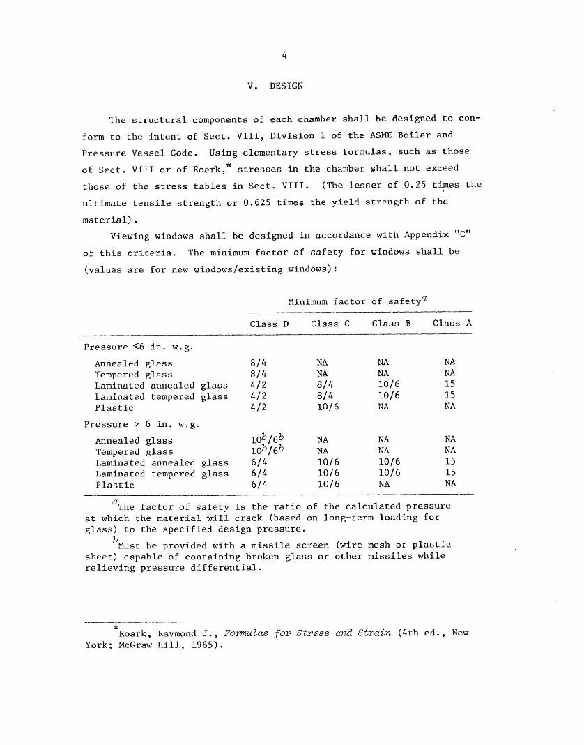
V. DESIGN
The s t r u c t u r a l components of each chamber shall be designed to con-
farm t o t h e i n t e n t of Sect. V I I I , Div is ion 1 of t h e ASME Bo i l e r and
P res su re Vessel Code. Using elementary stress formulas, such as those * of Sect. VI11 o r of Roark, stresses i n t h e chamber sha l l not exceed
those of t h e stress t a b l e s i n Sect. VIII. (The lesser of 0.25 t ines t h e
u l t i m a t e t e n s i l e s t r e n g t h OK 0.625 t i m e s t h e y i e l d s t r e n g t h of t h e
ma te r i a l )
Viewing windows s h a l l be designed i n accordance wi th Appendix "C"
of t h i s c r i t e r i a . The minimum f a c t o r of s a f e t y f o r windows sha l l be
(va lues are f o r new windowslexis t ing windows):
Minimum f a c t o r af sa fe tya __I. -- ___.._-
Class D Class 4: Class B Class A __I_ l_lllll .-*..
Pressu re G6 i n . w . g .
Annealed g l a s s 814. NA NA NA Tempered glass 8 / 4 NA NA NA Laminated annealed g l a s s 412 8 / 4 10/6 15 Laminated tempered glass 412 814 10/6 15 P l a s t i c 412 10/6 NA NA
Pressu re > 6 i n . w . g .
Annealed glass lob / 6b NA NA NA Tempered g l a s s 10b/6b NA NA NA Laminated annealed glass 6 / 4 1016 10/6 15
P l a s t i c 614 1016 NA NA Laminated tempered g l a s s 614 lO/6 1016 15
-___o.. -- Q The f a c t o r of s a f e t y is t h e ratio o f t h e c a l c u l a t e d p r e s s u r e
a t which t h e material w i l l crack (based on long-term loading f o r g l a s s ) t o t h e s p e c i f i e d des ign pressure .
'Must be provided wi th a m i s s i l e screen (wire mesh or p l a s t i c sheet) capable o f con ta in ing broken glass o r a t h e r missiles whi le r e l i e v i n g pressure d i f f e r e n t i a l .
,L
^Raark, Raymond J . , FornruZas for Stress and S t r a i n (4 th ed . , New York; McGraw H i l l , 1965).

1 cons ide ra t e s ign inc lude (
( c ) adequate v
cor ros ion r ontaminat ion,
ominal s i z e and
mbers, gloves
ces, a t least one
t p o r t s s h a l l eta1 o r 0 th
ed f o r c l o s u r
Bungs are pro e i n t e g r i t y of
dur ing the time . Covers s
and also seal o t h e chamber
to a g r e a t e r
ngs or cover
of a t o r n g lo in c o n t r o l l i n
bung o r cover
should be expl and t h e design shou
ment t h a t pur
t o keep a glove chamber i n wh
be intended
containment ba se i t does r
ed for h igh te xs, f i r e c o n t r
l e gas senso apor ana lyzer
equipment sh
rs provided w
vent f lood ing l eak , o r t o act s h a l l be equ
i f a leak occurs .

8. Elec t r ica l sa feguards s h a l l be provided f o r equipment and personnel .
The use of grounding, ground f a u l t i n t e r r u p t e r s , over load pro tec-
t i o n , and independent f u s i n g should be considered.
9 . Where p o s s i b l e , l i g h t sources s h a l l be i n s t a l l e d o u t s i d e of t h e
chamber.
10. I n t e r n a l co rne r s should be coved, t o f a c i l i t a t e c leaning .
11. I n t e r n a l weld s u r f a c e s s h a l l be ground f l u s h and smooth t o f a c i l i t a t e
c l ean ing ,,
12. Exhaust a i r connect ions s h a l l be provided w i t h d e b r i s s c reens t o
prevent t r a s h from e n t e r i n g exhaust systems and burning material
from reaching f i l t e r s . Cons idera t ion sha l l be given to t h e need
t o p r o t e c t exhaust f i l t e r s from h o t gases i n t h e event of a f i r e .
13. Consider p rov i s ion of a foot - or knee- opera ted s a f e t y swi tch
(with manual r e s e t ) t o t u r n o f f e l e c t r i c a l l y powered machinery
w i t h i n t h e chamber i n a d d i t i o n t o o t h e r c o n t r o l s .
14. An e a s i l y observed d i f f e r e n t i a l p r e s s u r e i n d i c a t o r s h a l l be provided
f o r each chamber,
15. I f used f o r Class A s e r v i c e chambers, "H" gaske t s shall be s e a l e d
t o t h e chamber and t o t h e window w i t h a mastic.
16 . Windows s h a l l be of t h e smallest s i z e t h a t w i l . 1 s a t i s f y f u n c t i o n a l
requirements .
VI. CONTROLLED ATMOSPHERE CHAMBER SYSTEMS
A c o n t r o l l e d atmosphere chamber system c o n s i s t s of the. chamber
i t s e l f and any o t h e r equipment, p ip ing , o r c o n t r o l s (permanent o r tem-
P O K ~ K Y ) that can a f f e c t i t s opera t ing cond i t ions , i nc lud ing ( I ) p r e s s u r e
and flow c o n t r o l s , (2) f i l t e r s , ( 3 ) f i r e c o n t r o l , ( 4 ) a s s o c i a t e d g loves ,
bags, p o r t c l o s u r e s , (5) p r e s s u r e r e l i e f dev ices , (6) exhaus t f a n s ,
(7 ) , exhaus t d u c t s ( t o a p res su re / f low c o n t r o l d e v i c e ) , (8) alarms,
i n d i c a t o r s , and monitors , and (9) h e a t sources .

7
iewed as a who
g cond i t ions
c i f i e d des ign cond i t t e d chambers. be
is control is t h e event of power E a i l u r e or
t i o n of any de m.
1. When a Class A, Class B
n l e t t o and d chamber. To
hese f i l t e r s
e f f i c i e n c y and
flow cannot be f i l t e r s does n t o v e r i f y tha
accep tab le flow ch
p rov i s ion f o r (
(2) p e r i o d i c r should be g ive a f low i n d i c
c o n t i n u a l l y mo e of a i r inf low,
wo s t a g e s of D f i l t e r s sha
series be fo re
f i l t e r s are n r r a d i o a c t i v e
abso rbe r s , o r also be used.
(c ) P ip ing , p r e s s u r e d and c o n t r o l s h a l l be such t h a t
a i r v e l o c i t y a n ing , w i th gl
removed, i s a t . Where demonstr
by a c t u a l test n taminat ion , c
e used t o de
s h a l l have UE and/or vac
i e f devices d e r no circumst
p r e s s u r e exc
c t i o n i n t h e manner. Re1
equ i red i f t h e connected t o a s
p r e s s u r e o r vacuum w.g. Conside
en t o t h e poss
f low c o n t r o l s 'and

8
3 . I f bubblers are used f o r p r e s s u r e o r vacuum r e l i e f , they s h a l l be
of t r anspa ren t c o n s t r u c t i o n t o permit a v i s u a l check for the
presence of t h e c o r r e c t q u a n t i t y of s e a l i n g f l u i d .
4 . Vacuum o r p re s su re r e l i e f devices of Class A, Class B, o r Class C
chambers shall be provided w i t h HEPA f i l t e r s . These f i l t e r s sha l l
not be shared w i t h any f lawing system,
The f i l t e r s are requi red s o t h a t contaminat ion r e l eased i n
connect ion with a p res su re surge (I) w i l l no t be r e l eased
t o t h e room o r (2) w i l l no t contaminate t h e exhaust duc t ing .
These f i l t e r s cannot a lso s e r v e a f lowing system because, i f
they d i d , they might became plu&ged under normal cond i t ions
and not be e f f e c t i v e when c a l l e d upon t o func t ion i n an
emergency.
5. System design s h a l l recognize any need f o r a h igh flow rate of gas
t o provide d i l u t i o n of flammable vapors o r d i s s i p a t i o n of hea t
loads , Operat ing procedures t o ensure t h a t t h e flow rate i s
adequately c o n t r o l l e d s h a l l be e s t ab l i shed .
6 . Considerat ion s h a l l be given t o t h e need f o r remote alarm systems
t o s i g n a l malfunct ions of t h e pressure c o n t r o l system when the
system is unattended. To be e f f e c t i v e , alarms must s i g n a l i n a
c o n t r o l l e d area which i s cont inuously monitored.
7. Considera t ion s h a l l be given t o the need f o r e lec t r ica l grounding
of metal chambers. Where needed, grounding s h a l l be provided,
8. The review of c o n t r o l l e d atmosphere chamber i n s t a l l a t i o n s s h a l l
be based on the assumption t h a t t h e r e w i l l be a fire, e i t h e r inside
o r nea r t h e chamber, P r o t e c t i v e systems s h a l l both minimize the
l i k e l i h o o d of a f i r e and minimize t h e consequences o f a f i r e .
9 . Considera t ian s h a l l be given t o sources of l i q u i d o r compressed
gases t h a t art3 connected t o the chamber. Such sources s h a l l be
provided with f low- l imi t ing o r i f i c e s o r €a i l - shu t r e g u l a t o r s t o
p r o t e c t t h e chamber from over p r e s s u r i z a t i o n .

9
V I I . BEFORE OPERATION
.
1.
2.
3 .
4 ,
1.
t i o n s t o be pe chamber s h a l l be r ev
e t h a t they i ons on t h e cha
e s i g n c o n d i t i a t t e n t i o n should
o s s i b l e use o might i g n i t e o r clamps o r p r e s s e s which might s l i p and release a missile.
The p res su re c o n t r demonstrated
a c t u a l demonstr ng mal func t io
imenta l manner, of c o n t r o l e lements , and by
t e r r u p t i n g t h e pa t t h e p r e s s u r e t h e ign p res su re .
a t e d as vacu
quipment) sha
y du r ing use
f e c t s o r damag i c h might prevent s
of t h e c o n t a i
Class c o n t a i n e r s hav g r e a t e r than f i v e l i ters
e r a t e d as vac uiprnent s h a l l be
p e r f o r a t e d metal p l a s t i c m i s s i
V I I I I . DURING OPERATION
flammable s o used i n Class A o r
l l e d atmosph flammable s o l
(a) The q u a n t i t y of 11 be r e s t r i c t e d t a
minimum necessary .
P rov i s ion s h a l
l a n k e t i n g t o
r d i l u t i n g vapors o r i n
( c ) A s quickly as p use, s o l v e n t s and t e d material s h a l l be
9c Acetone, a l coho l , benzene, ether, gaso l ine , naptha, to luene , etc.

REFERENCES
This document inco rpora t e s t h e following:
1. ORNL Safety Manual, Number 2 , 1 , i s sued J u l y 27 , 1971 (under r e v i s i o n ) .
2. OWL Safe ty Manual, Appendix A-3, i s sued November 11, 1974 (obso le t e
and removed from Manual) . This document accommodates the recommendations o f :
1. Lawrence Livermore Laboratory, V I . Gloved Boxes, August 15, 1972.
2. ASTM Standard C852 ( d r a f t ) , J u l y 1 9 , 1976.
Many r e fe rences d e a l w i t h the s u b j e c t of glsvebox (more generally
c o n t r o l l e d atmosphere chamber) s a f e t y . The fol lowing l i s t i s not
exhaus t ive .
1.
2.
3 .
4.
5.
Barton, C . J . A Review of Glove Box Construetion and Eqedmenta-
tion, Report ORNL 3078, Oak Ridge Nat iona l Laboratory, Oak Ridge,
TN, May 31, 1961.
Beckers, R. M. , R. I?. Denkins, W. M. Glen, T. J. Golson, J. E. Kahn,
G. W. Renfro, and J. A. Steed. Engineering Design L32.cXctices a t
ORNL f o r Facil i t ies Containing Radioactive MateriaZs, Report
ORNL/TM-1459, Oak Ridge Nat iona l Laboratory, Oak Ridge, TN, A p r i l
1966.
D'Arcy, John. Hot Laboratories, B r i t i s h Nuclear Forum, London.
Doming, W i l l i a m E. and Richard W. Woodard. GZovebox Fire Tests,
Report KFP-1557, The Dow Chemical Company, Rocky F l a t s Div is ion ,
Golden, CO, November 6 , 1970.
Doming W. E . New Fire Ppotection Systems for Fi l ter Plenums,
From Report CONF-700816, V o l . 2 , The Dow Chemical Company, Rocky
F l a t s Div is ion , Golden, CO.

. Dolphin, and I.
$dental Exposures t o I Radiations, Rep0
e y , Harwell,
s, Oak Ridge N y, Oak Ridge, 0 .
e
orpora t ion , 1
box Fire Sufet ctory Mutual Re
n Glove Boxes
tions i n Relation t o
n, Report AH ngdom A t o m i c
Ris ley , Warringto
1, L. No, and love-Box and
13. Jackson, C. , T. W. g l e r , and A. J. S
o r t mRE-R 30 o m
e Energy Auth rkshire l959.
y , Char les W. Materials. R e
ow Chemical C s Div i s ion , G
15 . r, Sidney F. n Protection o
Fucilit<es, Report September 1974.
16 k ing i n t o Glove Engineering,
, pp. 2 3 4 - 6 .
17. Merker, L. G. "De e n t and F a c i l i t i e
of PZutonim II

1 2
18 e
19.
20 L
21,
22 )*
23
24
25 e
26 e
27.
28
29 *
30.
Serious Accidents, "Fi re i n V e n t i l a t i n g System F i l t e r s ,I' I s sue N o
83, USAEC, J u l y 27, 1955.
Serious Accidents, "Explosion i n Glove-Box Line of Plutonium
F a c i l i t y , " I s sue No. 129, USAEC, October 28, 1957.
Serious Accidents, " S m a l l Metallic Plutonium F i r e L e a d s t o Major
Proper ty Damage L o s s , s v I s sue No. 130, USAEC, November 2 7 , 1957.
Ser-ious Accidents, "Drybax Explosion Disperses Plutonium Contamina-
t i o n , " I s sue No. 148, USAEC, October 8, 1959.
Serious Accidents, " P l a s t i c Windows and a $125,000 Spr ink le r Head,"
Issue No. 152, USAEC, October 29, 1959.
Serious Accidents, "Glove Box Explosion , I' I s s u e No. 180, USAEC,
November 20, 1961.
Semkus Accidents, " F i l t e r Box F i r e , " I s s u e No. 217 , USAEC,
February 7, 1964.
Serious Accidents, "Explosion Within Glovebox Disperses Contamina-
t i o n , " I s s u e No. 242, USAEC, January 11, 1965,
Serious Accidents, "Burning Plutonium Chips E x p l o d e i n Carbon
Te t r ach lo r ide Degreasing Bath, I s s u e No. 246, USAEC , March 1 2 , 1965
Serious Accidents, "Hazardous Solvent Use Causes Explosion i n a
Glovebox," Issue No. 261, USAEC, February 25, 1966.
Serious Accidents, "Maintenance on Plutonium Machining Coolant
Lines Leads t o $17,500 F i r e , " Issue No. 262, USAEC, March 4 , 1966.
Serious Acc<dents, "Plutonium F i r e Outside of Glovebox Leads to
$30,000 Contamination Cleanup Cost," Issue No. 264, USAEC, May 13,
1966.
Serious Accidents, " F i r e During Glovebox Cleanup Leads t o $23,000
Damage V i a Contamination Spread, 'I I s s u e No. 249 USAEC, J u l y 8 ,
1966.

13
s Accidents, Hot Cell Window," I
November 4 , 1
s Accidents, I' losion," Issue No. 2
ry 3 , 1967.
33. Ser-ious Accidents, " n Causes $ 4 2 , e and
toniun 238 Conta , I ' Issue No. 2 9 3 , us 1968
Serious Accidents, " Plan t - Play 11,
No. 306 , USAEC, Dece
35 u ious Accidents, " ssurization Three I n c i 1 1 
Issue No. 318, USAEC,
3 6 . son, M. A . (Ed.). of the Rocky f
on Safety i r t Pluton Zit<es, Report
Chemical Company, vision Golden,


15
.-
APPENDIX A
A.
onal Laborat
us ar,d that d r e l a t i v e t s t r u c t i o n , a
n t r o l l e d A t The term "co and is intend a sea led eo
are s u b j e c t t o re between f
e r a t o r can o
s s u r e d i f f e t t h e s e c r i ively sh ie lded
s where air
c .
spons ib l e f o r edure and of
ce over equip procedure an
t h e r e f e r e n Officer of a onsible i nd
he Division r controlled

16
.-- Number 2.1
Page __ 2 of ---. 2-.-...- Pages
Issued January 22, 1980
Supersedes Issue Dated July 27, 1971-
I>. Procedure
la The criteria €OK design, construction, and operatian of controlled atmosphere chambers intended for service at the Oak Ridge National Laboratory are presented in ORNL/TM-6865.
2 . Determination of the service class an operation requires shall be made by the responsible individual and the Division Safety Officer, consulting with the Office of Operational Safety and/or others as appropriate. This determination and i t s basis shall be documented in a memorandum.
3 . All new controlled atmosphere chambers s h a l l be in compliance with the mandatory requirements of the criteria before being put in service.
4 . Existing contro.lled atmosphere chambers shall be evaluated and:
a. Verified as being in compliance with the mandatory requirements of the criteria,
b. Brought into compliance with the mandatory requirements of the criteria, or
c . A written justification f o r exception from the mandatory requirements of the! criteria shall be submitted to and be accepted by t h e Division Safety Officer and the Office of Operational Safety.
Compliance with one of the above options shall be achieved by December 31, 1980.
5. Before operation, the responsible individual sha l l satisfy t he Division Safety Officer that all applicable requirements af these criteria have been satisfied, and specifically that the review and demonstration required by V I c I . 1 and VPIa2 o f the criteria have been performed. the Office of Operational Safety o r others as necessary. formance to the criteria sha l l be documented in a memorandum.
Assistance may be obtained from Con-
6 . Crazed or cracked viewing windows shall be reported to the Division Safety Officer and t o the Office o f Operational Safety. At the earliest opportunity, damaged windows im Class A , Class B, OK Class C chambers shall be replaced.

17
L
of
Number A-7
Page 3 of 5 Pages
Issued 12/22/70
Supersedes Issue Dated 9/15/70
2
otoxicity)
icity)
toxicity)
otoxicity)
6 , V-48, Fe-59, Co 1, Zr-95 -t Nb-95, Cd-109 -I- Ag-109, 1-131, CS-134, CS- -I- Pr-144, Pm-147, Ir-192, Hg-203, T1 Np-237, PU-242
Ca-47, Sc-47, Sc 72, AS-74, AS-76 9, Pd-103 -I- Rd-1 Te-127, Ba-131, Sm-153, Ko-170, 8-191, Ir-190, I Au-199, Hg-197, 4
A-37, Cr-51, Ni -129, 1-129, I- , U-238, U-natural
safety review
c for 40-hr wk
0. I, whichever is lation - Determine
-hr week for Am-24
Inverse specific activity
2.16 x lo9 x 6 x 1
the same hazard equivalent potential as 1 gram of Pu-239.
GI-am and curie HEP values for most s ar ed in Procedure 1.5 of th i s Pianual.

18
Supersedes I ssue Dated 9/15/70 _______
APPENDIX B - Page 2 of 2
Table 2
Type of labora tory wi th q u a n t i t y handled versus r a d i o t o x i c i t y - S P e Type B Type c Type D
....C_ --- Good chemical Radio toxic i ty High level Radiochemical Good chemical
labora tory labora tory labora tory labora tory of i s o t o p e s ____ -
Very high" > l O mCi 10 U C i - 10 mC.L 0 . 1 p c i - 10 uci 0 - 0 . 1 p c i
High >loo mci 100 p C i - 100 m C i 0 . 1 p c i - 100 p c i 0 - 1.0 p c i
Moderate >1 C i 1 m c i - 1 C i 10 pci - 1 m C i 0 - 10 p c i
S l i g h t >10 c i 10 m C i - 10 C i 100 p c i - 10 mci 0 - 100 p c i .- _ . . . ~ . I ..- --.-
aThere is an upper l i m i t t o t h e quant i ty of transuranlum elements which should be approved f o r glove box opera t ions . A s a genera l r u l e , f o r those i so topes having a gram HEP index number below t h e l i m i t i n g q u a n t i t y should be 100 mg. (For example, 100 mg of 244Cm generates t h e same hazard equiva len t p o t e n t i a l as 4.3 kg of 239Pu.) Any opera t ion involving more than 100 mg of such i so topes should be conducted a t f a c i l i t i e s wi th more absolu te containment f e a t u r e s than are of fered by glove boxes alone. This number may r e q u i r e f u r t h e r reduct ion due t o p e n e t r a t i n g r a d i a t i o n . of one meter i n a i r .
One gram of 252Cf, f o r example, generates a dose rate of 2400 remlhr at a d i s t a n c e
--. D e f i n i t i c n of Laboratory Types - Unless otherwise s t a t e d , t h e requirements of basic l abora tory or equal f a c i l i t y are understood.
Type A - Operations t o be conducted i n glove boxes or hot cel ls i n f a c i l i t i e s specifica1l.y con- s t r u c t e d f o r handl ing high l e v e l s of r a d i o a c t i v e materials. spread of a c t i v i t y wi th in o r release from the f a c i l i t y . from neighboring f a c i l i t i e s , l a b o r a t o r i e s , o f f i c e s , etc. , -is necessary. Glove boxes f o r t h i s s e r v i c e s h a l l comply wi th t h e requirements of t h e Glove Box Criteria document, ORUL/TM-6865.
Containment f e a t u r e s must prevent Complete i s o l a t i o n (phys ica l separa t ion)
Type B - Operations must. be conducted i n approved glove boxes. s h a l l comply wi th t h e requirements of t h e Glove Box Criteria Document, ORNI,/TM-6865.
Glove boxes f o r t h i s s e r v i c e
A degree of i s o l a t i o n such as hot change f a c i l i t i e s o r a i r locks t o prevent spread of contamina- t i o n t o surrounding o f f i c e s o r l a b o r a t o r i e s must be maintained.
=--- Operations must be conducted i n approved chemical hoods which are vented through high e f f i c i e n c y f i l t e r s , may be required f o r var ious hazardous opera t ions , e s p e c i a l l y i f hot p l a t e s , a s p i r a t o r s , o r Bunsen burners are used. Flame r e s i s t a n t P l e x i g l a s (Type SE-3) nay be used as a containment b a r r i e r f o r Type C labora tory opera t ions provided approval of t h e Radiat ion Control Off icer and Off ice of Operat ional Safe ty is obtained i n advance.
Hood openings must have a rnlninixm face v e l o c i t y of 100 fpm; however, 200 fpm
Type D -.- Bench-top opera t ion i s normally s a t i s f a c t o r y . f o r upper l e v e l s of a c t i v i t y .
Hood opera t ions should be considered
c
19
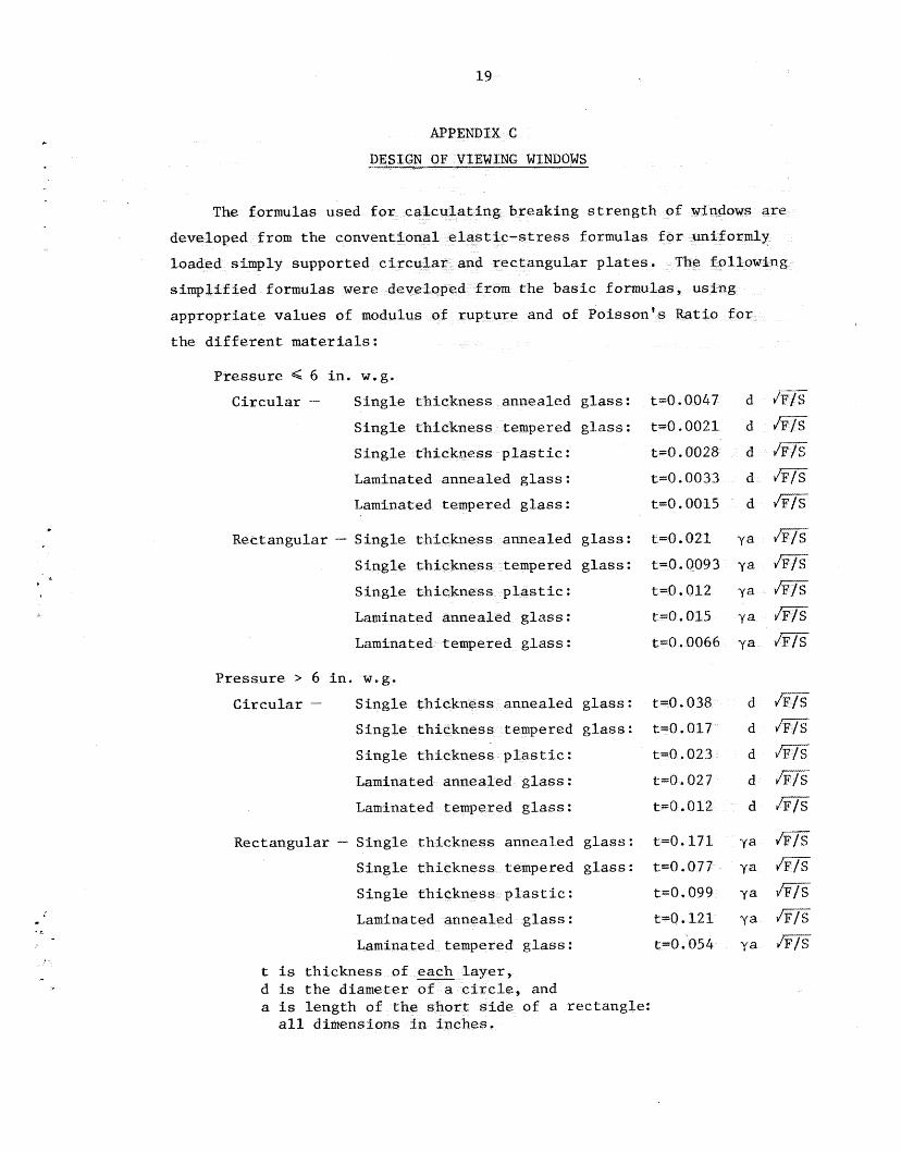
formulas used aking s t r e n
rom t h e conv ress formulas
ngular p l a t
formulas w e r e e basic form
and of Poisso
e n t materials:
.
Pressure 6 i n . w.g.
C i r c u l a r - s annealed glass:
t angu la r - Sing le
tempered g l a s s : t
re > 6 i n . w.g.
C i r c u l a r - S i s annealed glass: t = O . d m
empered g l a s s : t = O . d r n
d m
d m
La lass : t d m
Rectangular - S i annealed g l a s s : t=O.171, y a
e red g l a s s : t
t=0.099 y a h?iT t4.121 ya rn
y a m t is th ickness d is t h e d i a
e of a rec tangle :

20
Values of y have been computed f o r Poisson ' s Rat io of 0.20 (g l a s s )
and of 0.40 ( p l a s t i c ) and are presented i n Fig. 1. Figure 2 i n d i c a t e s
t h e upper l i m i t s o f the dimensions o f r ec t angu la r windows made of 1 / 4 i n .
t h i c k s a f e t y p l a t e (laminated) g l a s s and sub jec t ed t o G6 i n . w.g.
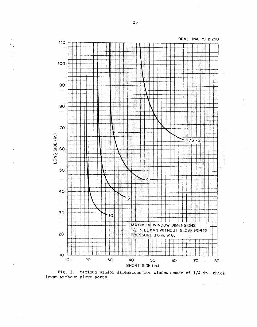
Figure 3 i n d i c a t e s t h e upper l i m i t s of t h e dimensions of r ec t angu la r
windows without glove p o r t s , made of 1 / 4 i n . t h i c k Lexan p l a s t i c and
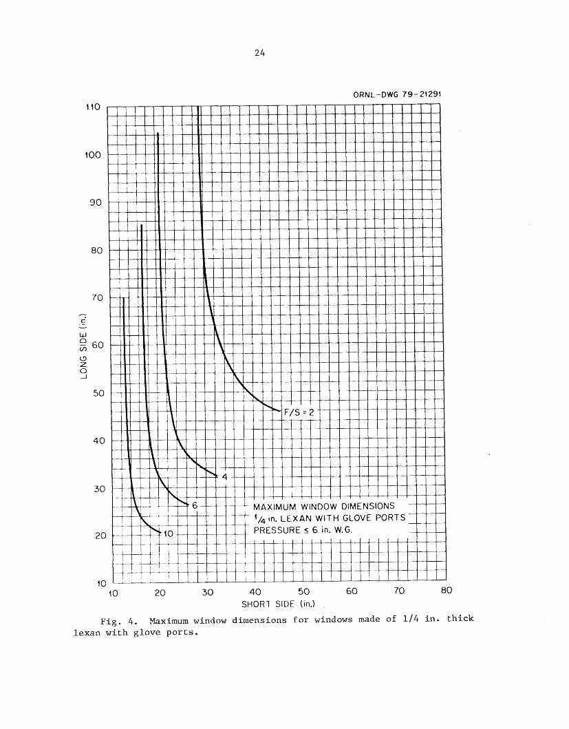
sub jec t ed t o G6 i n , w.g . F i g u r e 4 i n d i c a t e s t h e upper l i m i t s of the
dimensions of r ec t angu la r windows with glove p o r t s , made of 1 / 4 i n .
t h i c k Lexan p l a s t i c and sub jec t ed t o i n . wag.

21
Y
ORNL-DWG 79-20430
3.5 4 .O 4.5 1.5
ca l 1. Values of y stic f o r d i f r

22
80
60
50
3 0
2 0
10
0
Fig. 2. Maximum window dimensions fore windows made o f 1 / 4 i n . thick laminated sa fe ty g l a s s .
2 3
Le
2s
F i g . 4 . Maximum window dimensions f o r windows made of 1 / 4 i n . t h lexan wi th glove p o r t s .
ick

25
ORNL/TM-6865
IN'% E M AL D S T R 1 BUT I ON
1. H. 2. R. 3 . J. 4 . M. 5. E. 6. L. '7. G. 80 D e
9 . s. 10. J . 11. J.
12-61. I). 62. D. 6 3 . H. 6 4 . J. 65. T. 66. 11. 67. C. 68. J. 69. F. 70. L. 71. G. 72. E. 73. K. 74. w. 75. R.
L. Adair G. Affel E. Batey Bender s. Bomar L. Brown H. Burger D. Cannon D. Clinton E. Corum A. Cox T. Dice G. Dokerty F. Gale R. Gibson J. Golson R. Guinn E. Haynes E. Kahn A . Kappelmann J. King Q. Kirk H. Kobisk K. Kunot R. Laing E. Leuze
76 I) 7 7 . 78. 79. 80. 81, 82, 83
87. 88. 89. 90 e
91 CI
92 ,, 93. 94 c 95 " 96 .
97-99. LOO. 101.
102-103. 1 0 4 .
84-86 ,.
B a Lieberman
J. R. McGuffey W. II. Miller, Jr. C. A . Mills F. H. Neil1 H. A . Nelms M. E, Ramsey J. N. Robinson J. B. Ruch R. W. Schaich J. A . Setars M. H. Shanks J. W. Snider J. W e Stapletan J. R. Weir W. R. Whitson M. K. Wilkinson A . F. Zulliger Laboratory Records Laboratory Records, RC OWL Patent Office Central Research Library Document Reference Section
M. 1-1. Lloyd
71-12
EXTEI3NA-L DISTRIBUTION
105. Assistant Manager, Energy Research and Development, DOE-OR0 106-132. Technical Information Center, Oak Ridge, Tennessee 37830