creating an octo-banger controller, start to...
TRANSCRIPT
Creating an Octo-bangercontroller, start to finish
Purpose: This document will illustrate the steps required to build an OctoBanger controller from scratch. Please bear in mind that this is not a recipe, and we are not baking a cake here. If you wanted to merely copy every single step in this document, you could successfully mimic the results very easily.It is my hope; however, that people reading these instructions actually think about what they are doing, and realize that these are just suggestions and examples- not hard and fast rules. The controller in this example may or may not fit your prop's requirements.
Safety Disclaimer: I try to avoid switching mains voltages (120vac in the US, 220vac in most other countries) if I can help it. I do realize that bigger, more extravagant props use things like fog machines,AC motors, etc, so sometimes we must. If you are unfamiliar with electrical work of this nature, this document is absolutely no substitute for the training required for handling high voltage safely. If this isyour first project, I implore you to stick with 12vdc based lights, motors, and solenoids for your props. Messy wiring and ignorance can add up to fire, death and disaster very quickly!
OK, Let's Make a Prop ControllerBut First, we need to ask:
• How many channels do we really need?
• Are we going to want sound?
• Are we switching AC, DC, or both?
• How do we want to trigger the prop (Switch, PIR, etc.)?
For this fictitious/example prop, let's say we need to control:
• (2) 12vdc LED's, come on at the same time (only needs one channel)
• (2) 12vdc solenoid valves, independently switched
• (1) 12vdc LED spot light
• (1) Shiatzu massage motor
So looking at the above list, my first thought would be to use 4 mechanical relays (either in the form of a 4 relay module or shield), and a single SSR (solid state relay) for control of the AC motor.
I also plan to use sound, so I will need an MP3 module and amplified speakers of some sort.
Now that I have a general idea of what I am going to build, let's gather some parts:
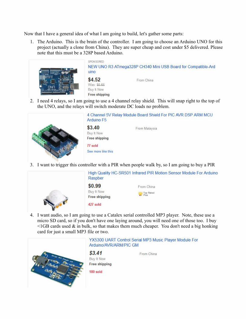
1. The Arduino. This is the brain of the controller. I am going to choose an Arduino UNO for thisproject (actually a clone from China). They are super cheap and cost under $5 delivered. Pleasenote that this must be a 328P based Arduino.
2. I need 4 relays, so I am going to use a 4 channel relay shield. This will snap right to the top of the UNO, and the relays will switch moderate DC loads no problem.
3. I want to trigger this controller with a PIR when people walk by, so I am going to buy a PIR
4. I want audio, so I am going to use a Catalex serial controlled MP3 player. Note, these use a micro SD card, so if you don't have one laying around, you will need one of those too. I buy <1GB cards used & in bulk, so that makes them much cheaper. You don't need a big honking card for just a small MP3 file or two.
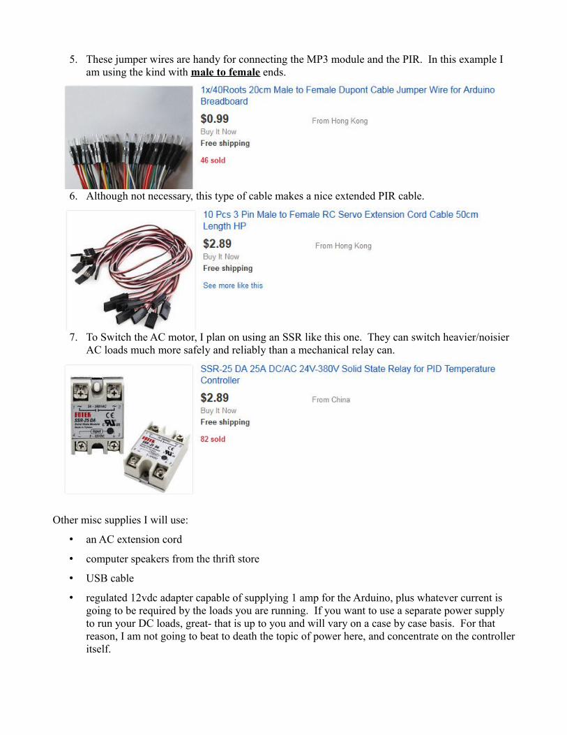
5. These jumper wires are handy for connecting the MP3 module and the PIR. In this example I am using the kind with male to female ends.
6. Although not necessary, this type of cable makes a nice extended PIR cable.
7. To Switch the AC motor, I plan on using an SSR like this one. They can switch heavier/noisier AC loads much more safely and reliably than a mechanical relay can.
Other misc supplies I will use:
• an AC extension cord
• computer speakers from the thrift store
• USB cable
• regulated 12vdc adapter capable of supplying 1 amp for the Arduino, plus whatever current is going to be required by the loads you are running. If you want to use a separate power supply to run your DC loads, great- that is up to you and will vary on a case by case basis. For that reason, I am not going to beat to death the topic of power here, and concentrate on the controlleritself.
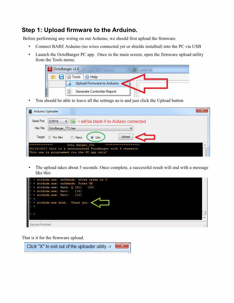
Step 1: Upload firmware to the Arduino. Before performing any wiring on our Arduino, we should first upload the firmware.
• Connect BARE Arduino (no wires connected yet or shields installed) into the PC via USB
• Launch the OctoBanger PC app. Once in the main screen, open the firmware upload utility from the Tools menu:
• You should be able to leave all the settings as-is and just click the Upload button
• The upload takes about 5 seconds. Once complete, a successful result will end with a message like this:
That is it for the firmware upload.
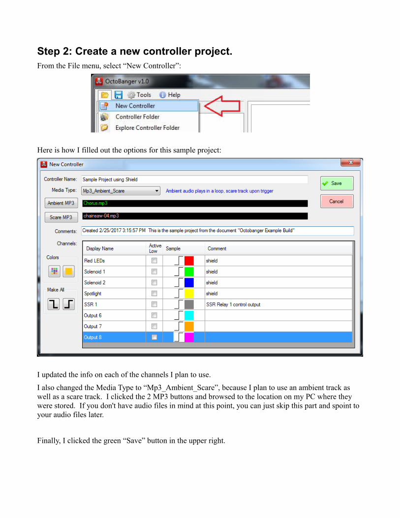
Step 2: Create a new controller project.From the File menu, select “New Controller”:
Here is how I filled out the options for this sample project:
I updated the info on each of the channels I plan to use.
I also changed the Media Type to “Mp3_Ambient_Scare”, because I plan to use an ambient track as well as a scare track. I clicked the 2 MP3 buttons and browsed to the location on my PC where they were stored. If you don't have audio files in mind at this point, you can just skip this part and spoint to your audio files later.
Finally, I clicked the green “Save” button in the upper right.
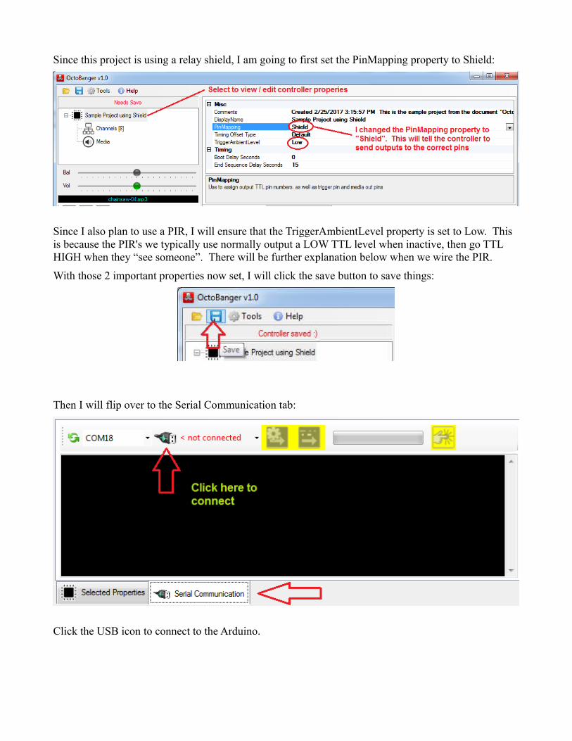
Since this project is using a relay shield, I am going to first set the PinMapping property to Shield:
Since I also plan to use a PIR, I will ensure that the TriggerAmbientLevel property is set to Low. This is because the PIR's we typically use normally output a LOW TTL level when inactive, then go TTL HIGH when they “see someone”. There will be further explanation below when we wire the PIR.
With those 2 important properties now set, I will click the save button to save things:
Then I will flip over to the Serial Communication tab:
Click the USB icon to connect to the Arduino.
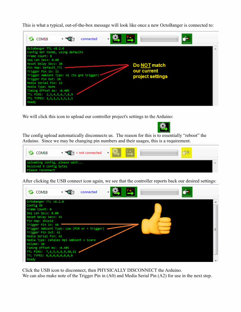
This is what a typical, out-of-the-box message will look like once a new OctoBanger is connected to:
We will click this icon to upload our controller project's settings to the Arduino:
The config upload automatically disconnects us. The reason for this is to essentially “reboot” the Arduino. Since we may be changing pin numbers and their usages, this is a requirement.
After clicking the USB connect icon again, we see that the controller reports back our desired settings:
Click the USB icon to disconnect, then PHYSICALLY DISCONNECT the Arduino.We can also make note of the Trigger Pin in (A0) and Media Serial Pin (A2) for use in the next step.
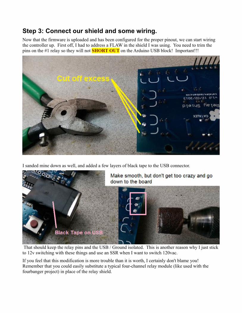
Step 3: Connect our shield and some wiring.Now that the firmware is uploaded and has been configured for the proper pinout, we can start wiring the controller up. First off, I had to address a FLAW in the shield I was using. You need to trim the pins on the #1 relay so they will not SHORT OUT on the Arduino USB block! Important!!!
I sanded mine down as well, and added a few layers of black tape to the USB connector.
That should keep the relay pins and the USB / Ground isolated. This is another reason why I just stick to 12v switching with these things and use an SSR when I want to switch 120vac.
If you feel that this modification is more trouble than it is worth, I certainly don't blame you! Remember that you could easily substitute a typical four-channel relay module (like used with the fourbanger project) in place of the relay shield.
Wiring, continued...
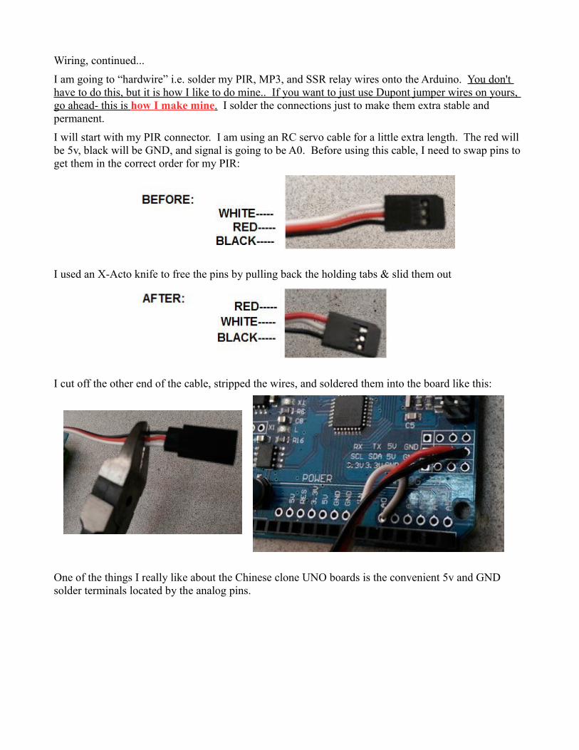
I am going to “hardwire” i.e. solder my PIR, MP3, and SSR relay wires onto the Arduino. You don't have to do this, but it is how I like to do mine.. If you want to just use Dupont jumper wires on yours, go ahead- this is how I make mine . I solder the connections just to make them extra stable and permanent.
I will start with my PIR connector. I am using an RC servo cable for a little extra length. The red will be 5v, black will be GND, and signal is going to be A0. Before using this cable, I need to swap pins to get them in the correct order for my PIR:
I used an X-Acto knife to free the pins by pulling back the holding tabs & slid them out
I cut off the other end of the cable, stripped the wires, and soldered them into the board like this:
One of the things I really like about the Chinese clone UNO boards is the convenient 5v and GND solder terminals located by the analog pins.
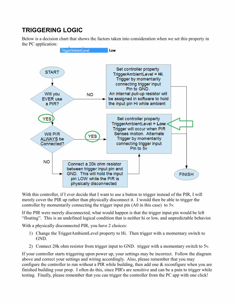
TRIGGERING LOGICBelow is a decision chart that shows the factors taken into consideration when we set this property in the PC application:
With this controller, if I ever decide that I want to use a button to trigger instead of the PIR, I will merely cover the PIR up rather than physically disconnect it. I would then be able to trigger the controller by momentarily connecting the trigger input pin (A0 in this case) to 5v.
If the PIR were merely disconnected, what would happen is that the trigger input pin would be left “floating”. This is an undefined logical condition that is neither hi or low, and unpredictable behavior.
With a physically disconnected PIR, you have 2 choices:
1) Change the TriggerAmbientLevel property to Hi. Then trigger with a momentary switch to GND.
2) Connect 20k ohm resistor from trigger input to GND. trigger with a momentary switch to 5v.
If your controller starts triggering upon power up, your settings may be incorrect. Follow the diagram above and correct your settings and wiring accordingly. Also, please remember that you may configure the controller to run without a PIR while building, then add one & reconfigure when you are finished building your prop. I often do this, since PIR's are sensitive and can be a pain to trigger while testing. Finally, please remember that you can trigger the controller from the PC app with one click!
Wiring, continued...
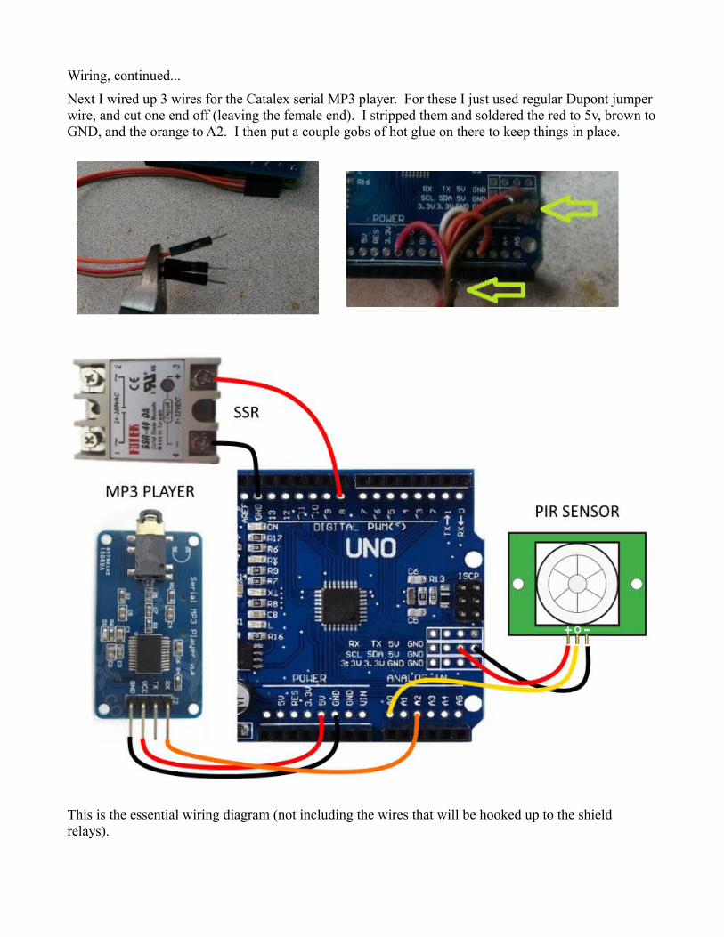
Next I wired up 3 wires for the Catalex serial MP3 player. For these I just used regular Dupont jumper wire, and cut one end off (leaving the female end). I stripped them and soldered the red to 5v, brown toGND, and the orange to A2. I then put a couple gobs of hot glue on there to keep things in place.
This is the essential wiring diagram (not including the wires that will be hooked up to the shield relays).
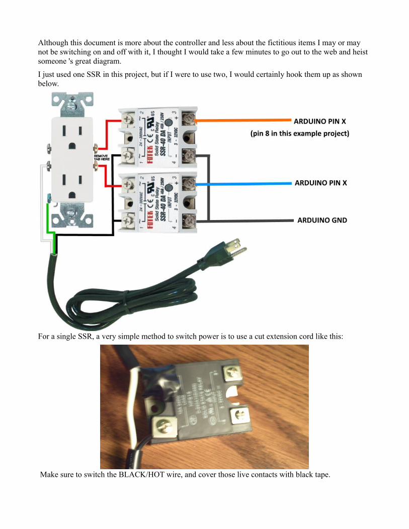
Although this document is more about the controller and less about the fictitious items I may or may not be switching on and off with it, I thought I would take a few minutes to go out to the web and heist someone 's great diagram.
I just used one SSR in this project, but if I were to use two, I would certainly hook them up as shown below.
For a single SSR, a very simple method to switch power is to use a cut extension cord like this:
Make sure to switch the BLACK/HOT wire, and cover those live contacts with black tape.
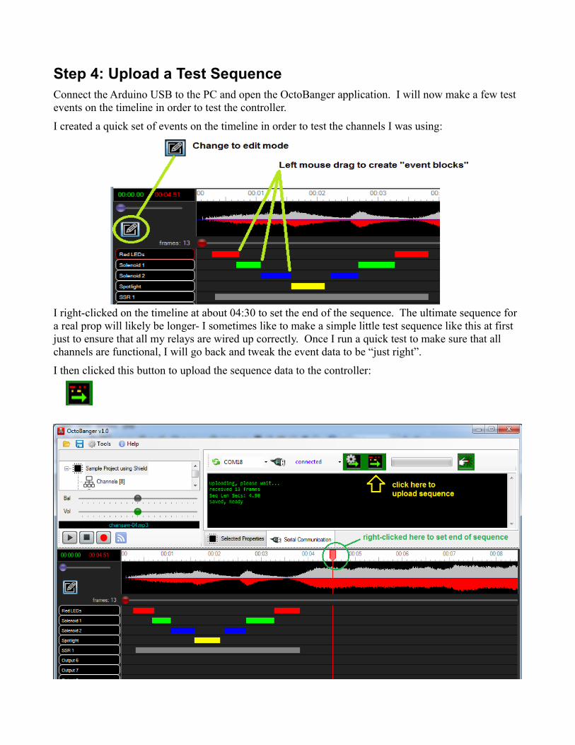
Step 4: Upload a Test SequenceConnect the Arduino USB to the PC and open the OctoBanger application. I will now make a few test events on the timeline in order to test the controller.
I created a quick set of events on the timeline in order to test the channels I was using:
I right-clicked on the timeline at about 04:30 to set the end of the sequence. The ultimate sequence for a real prop will likely be longer- I sometimes like to make a simple little test sequence like this at first just to ensure that all my relays are wired up correctly. Once I run a quick test to make sure that all channels are functional, I will go back and tweak the event data to be “just right”.
I then clicked this button to upload the sequence data to the controller:
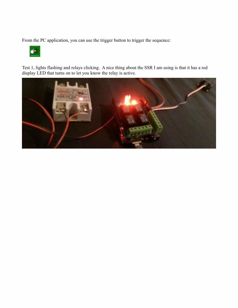
From the PC application, you can use the trigger button to trigger the sequence:
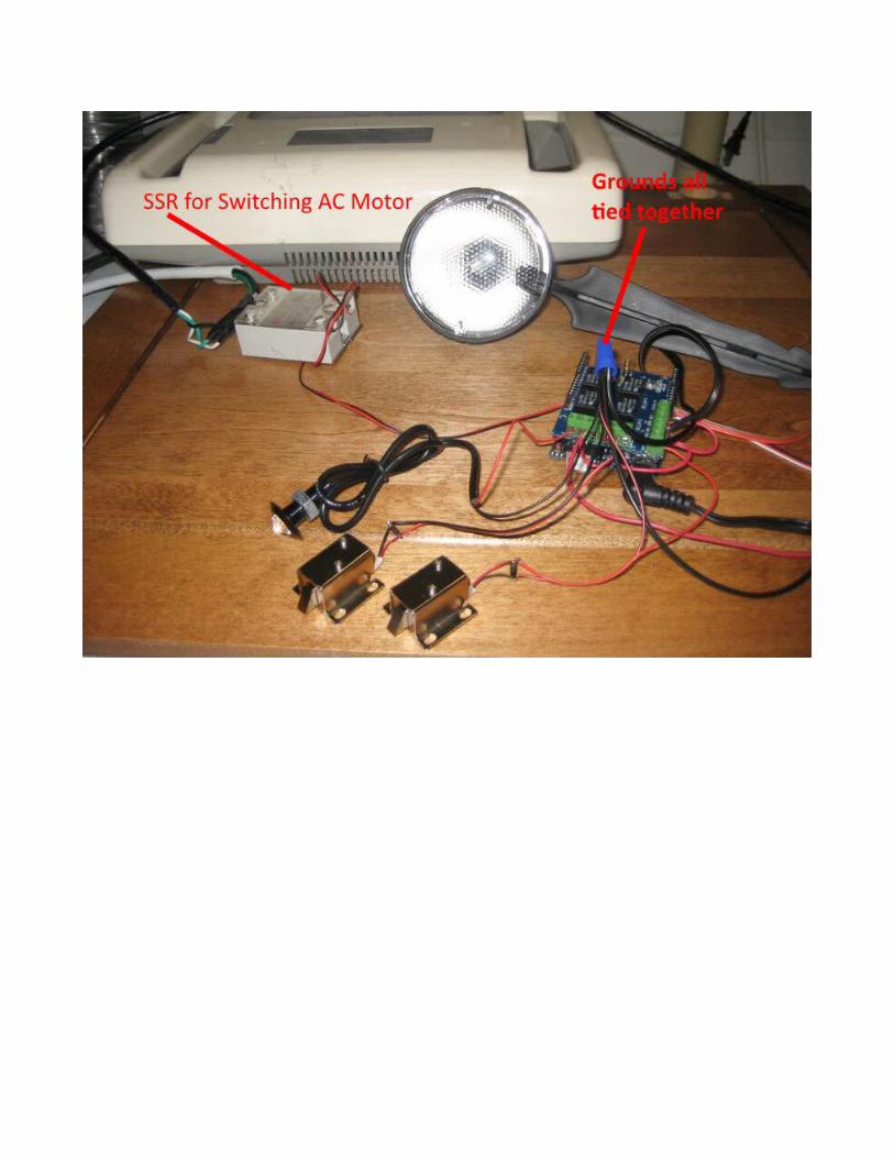
Test 1, lights flashing and relays clicking. A nice thing about the SSR I am using is that it has a red display LED that turns on to let you know the relay is active.
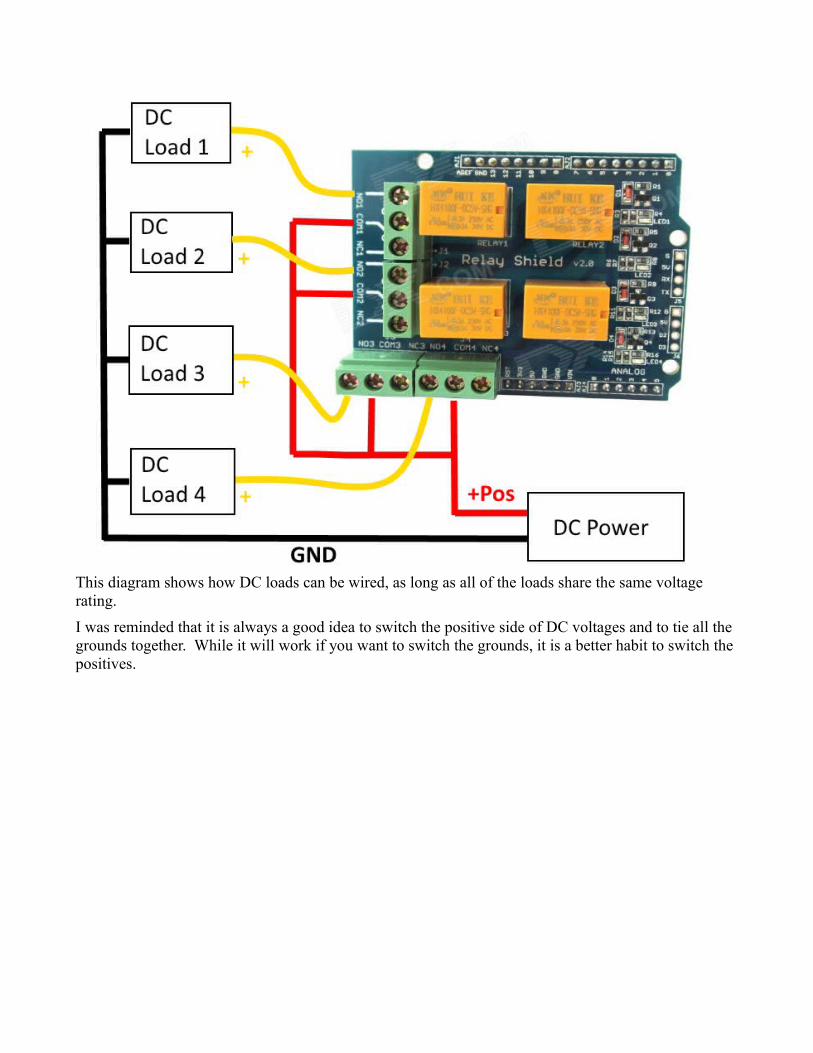
This diagram shows how DC loads can be wired, as long as all of the loads share the same voltage rating.
I was reminded that it is always a good idea to switch the positive side of DC voltages and to tie all the grounds together. While it will work if you want to switch the grounds, it is a better habit to switch the positives.