create csv files from drawing data - skysof software - · pdf file · 2013-04-28the...
TRANSCRIPT

Ultra AutoCAD Tool
by SkySof Software Inc.
Download: http://www.getfilez.com/acadtool.exe
1. Introduction
Ultra AutoCAD Tool is a FREE powerful utility program for AutoCAD drawing files. Features include: extract
data from drawing files (CSV, XML, HTML), create DXFs from DWGs, find and replace text, find and replace
block attribute values, find and delete text objects, find and delete block attribute objects, find and delete block
objects, set layer status (on/off/thawed/frozen), save drawings as older version, find and replace image paths, find
and replace external reference paths, etc. Ultra AutoCAD does not require AutoCAD to be installed on your
machine and is compatible will all versions of AutoCAD drawings. Ultra AutoCAD Tool requires Microsoft Data
Access Components (MDAC) for some operations to function properly. This software is free and available for
download from the internet at http://msdn.microsoft.com/data/mdac/downloads/default.aspx After installing MDAC
you must unload Ultra AutoCAD Tool then reload.
2. Create CSV files from drawing data
Select “Create CSV files from drawing data” from the Operation Tab and click the “Next” button.

Click the “Add File” button.
Select ATTEXT.DWG and click the “Open” button. Click the “Cancel” button.

The AutoCAD drawing now appears in the list of selected drawings. With the registered version it is possible to add
hundreds, even thousands of drawing files to this list. Imagine how time consuming and tedious it would be to
manually change a company name (in block attribute values or text values) for thousands of drawings. With Ultra
AutoCAD Tool you can perform this task in mere seconds! Hopefully you are starting to realize some of the
benefits of this invaluable tool.
Click the Next button to move to the next screen.
Now we will select the fields to include in the CSV file. For this demonstration we will select all the available fields
by clicking the “>>” button.

All fields should now exist in the right list box. For this demonstration we will create the CSV file in the same
directory as the drawing, extract block attribute data, and include field headings in the CSV file. To specify a record
filter type layout = ‘model’ and name = ‘d00005d1’ and layername = ‘xt’ in the Record filter text box. Note that
only specific fields can be used in the filter. Click the “?” button to see record filter help and a list of all available
fields. To build the CSV file click the “Process” button. If all goes well you will see a message “1 items processed”
in the status message at the bottom of the screen. If an error had occurred you would see a message box containing
error information (provided you have the error messages turned on via the System menu).
Open Window’s Explorer and look in folder C:\Program Files\Ultra AutoCAD Tool to verify if the file was created.

Open the file in any text editor such as Window’s Notepad. Note that only records where the layout name is equal
to ‘model’ and layer name is equal to ‘xt’ and block name is equal to ‘d0005d1’ appear in the file (as specified in
the record filter).
If Excel is installed on your machine double-clicking on the CSV file should open it in an Excel workbook.

3. Create DXF files from drawings
Select “Create DXF files from drawings” from the Operation Tab and click the “Next” button.
Click the “Add File” button to add drawing file ATTEXT.DWG then click the “Next” button.

Change the DXF version to “14” and the number of decimal digits to “9”. Click the “Process” button to create the
DXF file. If all goes well you should see “1 items processed” at the bottom of the screen.
Browse to folder C:\Program Files\Ultra AutoCAD Tool and open the DXF file with any text editor such as
Window’s Notepad.

Note that some numbers have 9 decimal places.
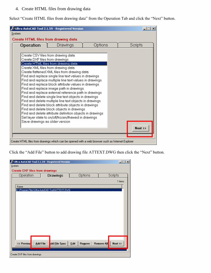
4. Create HTML files from drawing data
Select “Create HTML files from drawing data” from the Operation Tab and click the “Next” button.
Click the “Add File” button to add drawing file ATTEXT.DWG then click the “Next” button.

Select “Layers” from the “Drawing Data to Extract” group box. Click the “>>” button to select all available fields
and type name like ‘x%’ into the record filter text box. All layer names which begin with the letter “x” will be
selected from the drawing. Click the “Process” button to generate the HTML file.
If all goes well file C:\Program Files\Ultra AutoCAD Tool\ATTEXT.htm will be created. Double-click on the file
to open it with your default web browser.

This is a screenshot of the HTML file opened with Internet Explorer. Note that all the layer names begin with an
“X”.

5. Create XML files from drawing data
Select “Create XML files from drawing data” from the Operation Tab and click the “Next” button.
Click the “Add File” button to add drawing file ATTEXT.DWG then click the “Next” button.

Select “Blocks” from the “Drawing Data to Extract” group box and click the “Process” button.
File C:\Program Files\Ultra AutoCAD Tool\ATTEXT.xml should be created. Double-click on the file to open it
using your default XML viewing program.

This is the XML file opened with Internet Explorer.

6. Create flattened XML files from drawing data
Select “Create flattened XML files from drawing data” from the Operation Tab and click the “Next” button.
Flattened XML files are of a two dimensional format and can be easily imported into a record set.
Click the “Add File” button to add drawing file ATTEXT.DWG then click the “Next” button.

Select “Blocks” from the “Drawing Data to Extract” group box and click the “Process” button. Note that “Drawing
Name” is set to “FullName” (path and file name).
File C:\Program Files\Ultra AutoCAD Tool\ATTEXT.xml should be created. Double-click on the file to open it
using your default XML viewing program.

This is the XML file opened with Internet Explorer.

7. Find and replace single line text values in drawings
Select “Find and replace single line text values in drawings” from the Operation Tab and click the “Next” button.
This is one of the most powerful features of Ultra AutoCAD Tool.
Click the “Add File” button to add drawing file ATTEXT.DWG then click the “Next” button.

Type ABC Company in “Text to find” text box, XYZ Company in the “Replacement text” text box, and block =
‘d00005d1’ in the “Record filter” text box. Click the “Process” button.
A warning message will appear. Click the “Yes” button to begin replacing text in the drawing.

8. Find and replace multiple line text values in drawings
Select “Find and replace multiple line text values in drawings” from the Operation Tab and click the “Next” button.
Click the “Add File” button to add drawing file 8th
floor lighting.DWG then click the “Next” button.

Type to circuit shown in “Text to find” text box and to circuit displayed in the “Replacement text” text box then
click the “Process” button.

A warning message will appear. Click the “Yes” button to begin replacing text in the drawing.

9. Find and replace block attribute values in drawings
Select “Find and replace block attribute values in drawings” from the Operation Tab and click the “Next” button.
Finding and replacing block attribute values is another very powerful feature of Ultra AutoCAD Tool.
Click the “Add File” button to add drawing file ATTEXT.DWG then click the “Next” button.

Type * in “Text to find” text box, John Doe in the “Replacement text” text box, and attributetag = ‘drawn_by’
and layout = ‘layout1’ then click the “Process” button. The asterisk (*) is a special character which means “find
any text value”.
A warning message will appear. Click the “Yes” button to begin replacing text in the drawing.

Now we will change the every occurrence of john doe to Charlie Brown. Select check boxes “Find whole word
only” and “Replace whole value”. Click the “Process” button.
A warning message will appear. Click the “Yes” button to begin replacing text in the drawing.

10. Find and replace image path in drawings
The drawing files provided with Ultra AutoCAD Tool do not contain image paths. Therefore, you should test this
operation with one of your own drawing files with image paths. Select “Find and replace image paths in drawings”
from the Operation Tab and click the “Next” button.
Add a drawing containing image paths then enter then drawing path to find and the drawing path to replace then
click the “Process” button.

11. Find and replace external reference path in drawings
Select “Find and replace image paths in drawings” from the Operation Tab and click the “Next” button.
Click the “Add File” button to add drawing file 8th
floor lighting.dwg then click the “Next” button.

Type 8th
floor plan as “Text to find” and 10th
floor plan as “Replacement text”. Click the “Process” button.
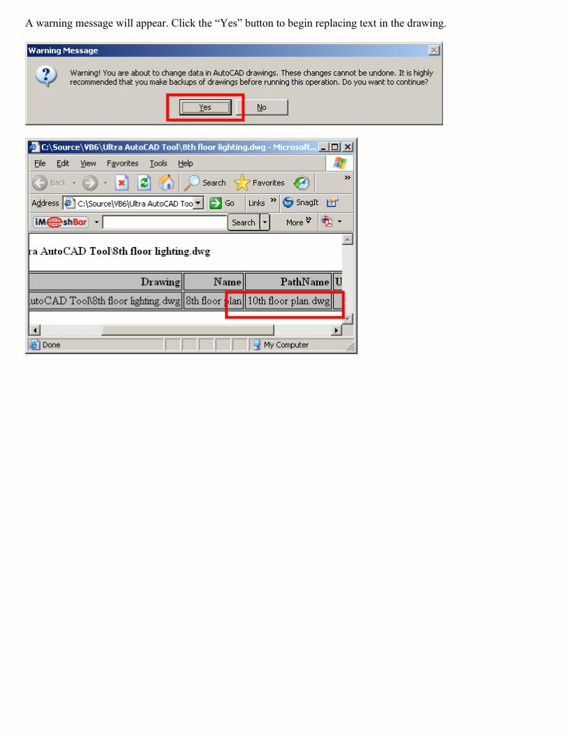
A warning message will appear. Click the “Yes” button to begin replacing text in the drawing.

12. Find and delete single line text objects in drawings

Text before deletion.

13. Find and delete multiple line text objects in drawings


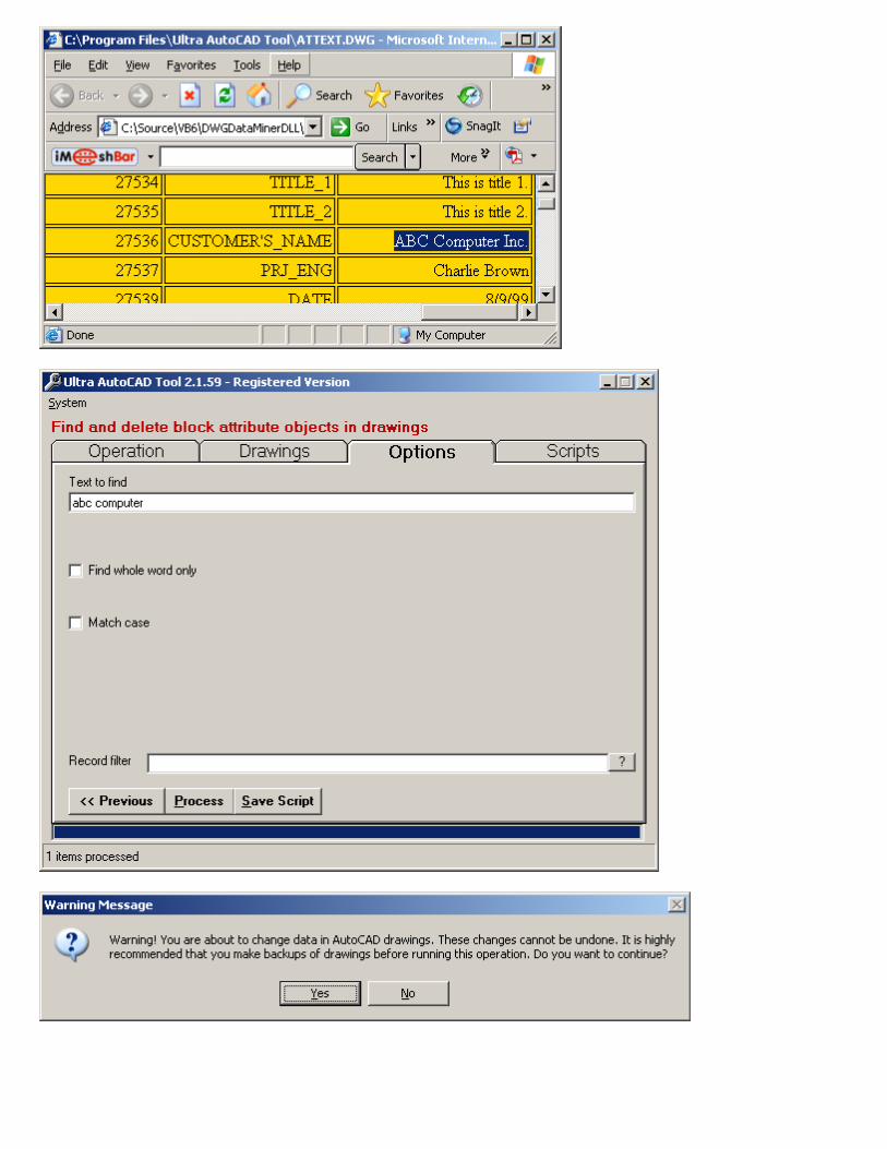
14. Find and delete block attribute objects in drawings


15. Find and delete block objects in drawings
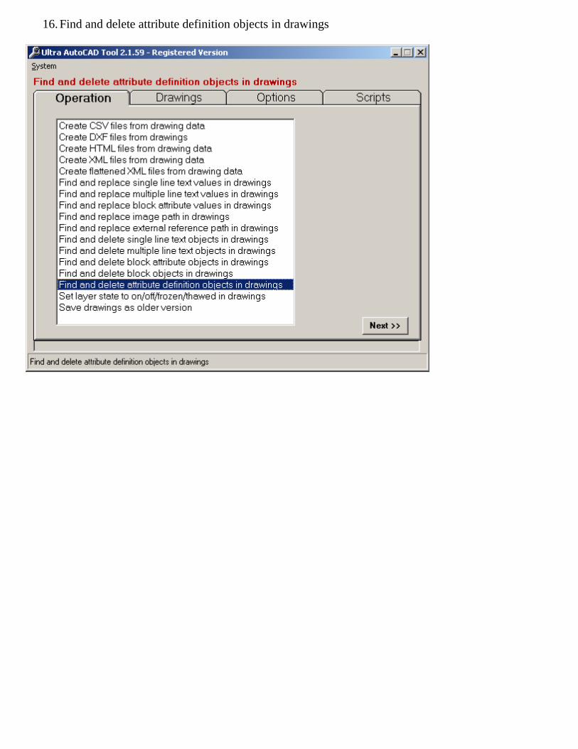
16. Find and delete attribute definition objects in drawings

17. Set layers on/off/frozen/thawed in drawings


18. Save drawings as older version


19. Saving and running script files
Script files are simply text files which store information for a specific operation thus allowing you to run that
operation at a later date by just clicking a few buttons. In this exercise we will create a script file which will create
an HTML containing drawing layer data.
Select “Create HTML files from drawing data” from the Operation Tab and click the “Next” button.
Click the “Add File” button to add drawing file ATTEXT.DWG then click the “Next” button.
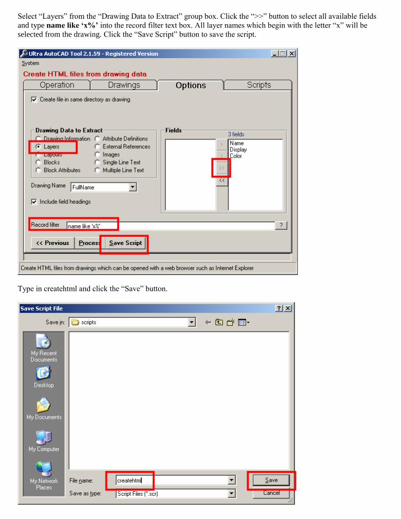
Select “Layers” from the “Drawing Data to Extract” group box. Click the “>>” button to select all available fields
and type name like ‘x%’ into the record filter text box. All layer names which begin with the letter “x” will be
selected from the drawing. Click the “Save Script” button to save the script.
Type in createhtml and click the “Save” button.

You will then see this message confirming that the script file was saved. Click the “OK” button to continue.
Close Ultra AutoCAD Tool then reload it. You will now run the script file you just created. Click the “Scripts” tab.
Click the button to open the script file.

Select script file createhtml.scr and click the “Open” button.
Your screen should now resemble this. Click the “Process” button to run the script.

Browse to folder C:\Program Files\Ultra AutoCAD Tool to confirm that the HTML file was created. Double-click
on file ATTEXT.HTM to open it with your default web browser.
Script files can also be run from Ultra AutoCAD Tool in “quiet” mode from the command prompt. Click Window’s
Start Button which is typically located at the lower left corner of the screen. Select “Run…” and type "C:\Program
Files\Ultra AutoCAD Tool\acadtool.exe" C:\Program Files\Ultra AutoCAD Tool\scripts\createhtml.scr then
click the “OK” button to run the script. File C:\Program Files\Ultra AutoCAD Tool\ATTEXT.HTM will be created.
You can create batch (BAT) files which contain several script command lines. For example:
"C:\Program Files\Ultra AutoCAD Tool\acadtool.exe" C:\Program Files\Ultra AutoCAD Tool\scripts\createdxf.scr
"C:\Program Files\Ultra AutoCAD Tool\acadtool.exe" C:\Program Files\Ultra AutoCAD Tool\scripts\createcsv.scr

20. Saving and running project files
Project files are simply text files which contain multiple script files. Running a project file runs each script file
contained within that project file. To create a project file click the “Scripts” tab.
Click the “Add Script to List” button.

Select file createhtml.scr and click the “Open” button to add the script to a new project. For this demonstration we
will only add one script. In reality we could have added as many as we wanted. Click the “Cancel” button.
Notice that the script now appears in the new project list. Click the “Save Project” button.
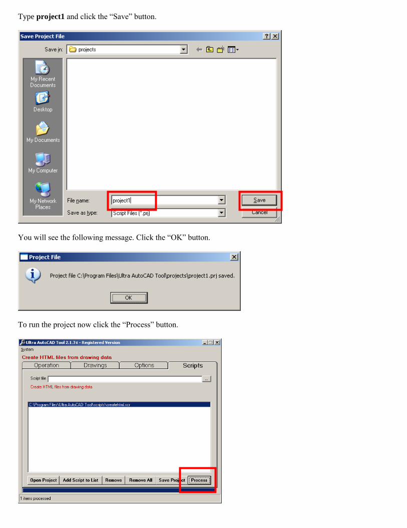
Type project1 and click the “Save” button.
You will see the following message. Click the “OK” button.
To run the project now click the “Process” button.

Project files can also be run from Ultra AutoCAD Tool in “quiet” mode from the command prompt. Click
Window’s Start Button which is typically located at the lower left corner of the screen. Select “Run…” and type
"C:\Program Files\Ultra AutoCAD Tool\acadtool.exe" C:\Program Files\Ultra AutoCAD
Tool\projects\project1.prj then click the “OK” button to run the project. File C:\Program Files\Ultra AutoCAD
Tool\ATTEXT.HTM will be created.