crating, shipping, and handling for control...
TRANSCRIPT

Approve
ISA–RP
R E C O M M E N D E D P R A C T I C E
60.11–1991
Crating, Shipping,and Handling forControl Centers
d 14 December 1990
Copyright 1991 by the Instrument Society of America. All rights reserved. Printed in the UnitedStates of America. No part of this publication may be reproduced, stored in a retrieval system, ortransmitted in any form or by any means (electronic, mechanical, photocopying, recording, orotherwise), without the prior written permission of the publisher.
ISA67 Alexander DriveP.O. Box 12277Research Triangle Park, North Carolina 27709
ISA–RP60.11–1991, Crating, Shipping and Handling for Control Centers
ISBN 1-55617-229-X
Preface
This preface is included for informational purposes and is not part of ISA-RP60.11-1991.
This standard has been prepared as part of the service of the ISA toward a goal of uniformity in the field of instrumentation. To be of real value, this document should not be static, but should be subject to periodic review. Toward this end, the Society welcomes all comments and criticisms, and asks that they be addressed to the Secretary, Standards and Practices Board, ISA, 67 Alexander Drive, P. O. Box 12277, Research Triangle Park, NC 27709, Telephone (919) 549-8411, e-mail: [email protected].
The ISA Standards and Practices Department is aware of the growing need for attention to the metric system of units in general, and the International System of Units (SI) in particular, in the preparation of instrumentation standards. The Department is further aware of the benefits to U.S.A. users of ISA standards of incorporating suitable references to the SI (and the metric system) in their business and professional dealings with other countries. Toward this end, this Department will endeavor to introduce SI-acceptable metric units in all new and revised standards to the greatest extent possible. The Metric Practice Guide, which has been published by the Institute of Electrical and Electronics Engineers as ANSI/IEEE Std. 268-1982, and future revisions, will be the reference guide for definitions, symbols, abbreviations, and conversion factors. Certain metric units that are not a part of the SI system are in common accepted use. This standard uses bar as a pressure measurement that is convertible to kilopascals by multiplying by 100.
It is the policy of the ISA to encourage and welcome the participation of all concerned individuals and interests in the development of ISA standards. Participation in the ISA standards-making process by an individual in no way constitutes endorsement by the employers of the individual, of the ISA, or of any of the standards that ISA develops.
The persons listed below served as active members of the ISA Control Centers Committee for the major share of its working period.
NAME COMPANY
R. W Borut, Chairman The M. W. Kellogg CompanyG. R Erk, Secretary Sun Company, Inc,J. M. Fertitta, Secretary* The Foxboro CompanyA. R. Alworth Shell Oil Company (Retired)C. D. Armstrong Tennessee Valley AuthorityB. W. Ball Brown & Root, Inc.C. Goding BIF Sanitrol, Unit of General SignalT. P. Holland Johnson Controls, Inc.- Panel UnitJ. F. Jordan Monsanto CompanyJ. G. McFadden Public Service Electric & GasR. F Rossbauer Fischer & PorterH. R. Solk, Chairman** Comsip Customile Corporation
*Secretary Emeritus**Chairman Emeritus
ISA-RP60.11-1991 3
A. Stockmal ContravesM. J. Walsh Procon, Inc.R. L. Welch El Paso Natural Gas CompanyF. Aured Panels, Inc.
The persons listed below served as corresponding members of the ISA Control Centers Committee for the major share of its working period:
NAME COMPANY
J. Cerretani Detriot Edison CompanyN. L. Conger Continential Oil CompanyL. Corsetti Crawford & Russell, Inc.T. J. Crosby Robertshaw ControlsC. R. Davis EngineerH. P. Fabish Fluor Engineering & Constructors, Inc.J. Farina Gismo Div. of Guarantee Electric Co.H. L. Faul, Jr. A-E Development CorporationM. E. Gunnin Swanson Engineering & ManufacturingR. E. Hetzel Instrument Control EnterprisesR. I. Hough Hough AssociatesJ. R. Jordon International Paper CompanyH. Kamerer Wilmington Sheet Metal Ind.A. Kayser Malcom Pirnie, Inc.J. L. Kern Weyerhauser Company- Corporate
Engineering DepartmentR. W. Kief Emanson CompanyA. L. Kress 3M CompanyR. A. Landthorn Panels, Inc.A. J. Langelier EngineerC. S. Lisser, Chairman* Oak Ridge National LaboratoryS. F. Luna General Atomics CompanyR. G. Marvin Dow Chemical CompanyA. P McCauley, Jr. Chargrin Valley Controls, Inc.W. B. Miller Moore Products CompanyC. W. Moehring BechtelD. P. Morrison BIF/General SignalR. Munz Mundix Controls Centers, Inc.R. L. Nickens Reynolds Metal CompanyF. W. Reichert EngineeringJ. F. Walker Honeywell, Inc.G. Walley The N/P CompanyW. T. Williams Instrumentation EngineeringW. J. Wylupek Moore Products Company
This standard was approved for publication by the ISA Standards and Practices Board in December, 1990.
*Chairman Emeritus
4 ISA-RP60.11-1991
NAME COMPANY
H. D. Baumann H. D. Baumann Assoc., Ltd.G. F. Bianchi Kent- Tieghi SpaD. N. Bishop Chevron USA, Inc.P. Bliss* ConsultantW. Calder III* The Foxboro CompanyB. A. Christensen* Continental Oil Company (Retired)L. N. Combs* ConsultantN. L. Conger Fisher Controls Int'l., Inc.R. L. Galley* ConsultantC. R. Gross Eagle TechnologyT. J. Harrison* FAMU/FSU College of EngineeringH. S. Hopkins Utility Products of ArizonaR. T. Jones* Philidelphia Electric Co.R. B. Jones Dow Chemical Company (USA)R. E. Keller* ConsultantO. P. Lovett, Jr.* ConsultantE. C. Magison* Honeywell, Inc.R. G. Marvin* ConsultantA. P. McCauley, Jr. Chargrin Valley Controls, Inc.W. B. Miller* Moore Products, Inc.J. W. Mock* Bechtel Western Power CorporationE. M. Nesvig ERDCO Engineering Corp.G. Platt* ConsultantR. D. Prescott Moore Products CompanyD. E. Rapley Rapley Engineering ServicesR. H. Reimer Allen-Bradley Company J. Rennie Factory Mutual Research Corp.W. C. Weidman Gilbert/Commonwealth, Inc.J. R. Whetstone Nat'l Inst. of Standards & TechnologyM. A. Widmeyer The Supply SystemC. A. Williams Eastman Kodak CompanyJ. R. Williams* Stearns Catalytic Corporation
*Director Emeritus
ISA-RP60.11-1991 5


Foreword
This recommended practice is one of a series that makes up the control center recommended practices, ISA-RP60. The individual sections provide continuity of presentation, convenience of reference, and flexibility of revision. The complete recommended practice consists of the following sections:
SECTION TITLE SCOPE
RP-60.1 Control Center Guide for preparation of engineering Facilities designs and specifications for control
center facilities.
RP60.2 Control Center Design methods and terminologyDesign Guide used in the specification of control Terminology center facilities.
RP60.3 Human Engineering of Design concepts accommodatingControl Centers man’s physiological and
psychological capabilities.
RP60.4 Documentation for Guide to the documentation Control Centers associated with control center
specifications.
RP60.5 Control Center Guide to the use of available graphicGraphic Displays display techniques.
RP60.6 Nameplates, Labels, Guide to the methods of identificationand Tags for Control of control center equipment and parts.Centers
RP60.7 Control Center Guide to control center profiles,Construction fabrication and finish methods, and
enclosure selection.
RP60.8 Electrical Guides Design concepts for control centerfor Control Centers electrical requirements.
RP60.9 Piping Guide for Design concepts for control center Control Centers piping requirements.
RP60.10 Control Center Guide to the methods of inspectionInspection and Testing and testing prior to control center
acceptance.
RP60.11 Crating, Shipping, Guide to the available methods forand Handling for control center crating, shipping, andControl Centers handling.
ISA-RP60.11-1991 7


Contents
1 Scope .............................................................................................................................. 11
2 Definitions ...................................................................................................................... 11
3 Design considerations .................................................................................................. 11
4 Crating ............................................................................................................................ 14
4.1 Construction ......................................................................................................... 14
4.2 Types of crating .................................................................................................... 19
4.3 Selection of crate .................................................................................................. 22
4.4 Humidity protection ............................................................................................... 22
4.5 Marking for shipment and storage ........................................................................ 27
5 Shipping ......................................................................................................................... 29
5.1 Shipping modes .................................................................................................... 29
5.2 Preparation for shipment ...................................................................................... 32
5.3 Instrument care ..................................................................................................... 34
5.4 FOB and insurance ............................................................................................... 34
6 Handling methods ......................................................................................................... 35
6.1 General ................................................................................................................. 35
6.2 Handling methods ................................................................................................. 35
6.3 Lifting eyes ........................................................................................................... 36
6.4 Job site protection ................................................................................................ 37
6.5 Shipping monitors ................................................................................................. 37
7 Storage ........................................................................................................................... 37
7.1 General ................................................................................................................. 37
7.2 Conditions that can be damaging ......................................................................... 37
7.3 Conditions that will help protect the control center ............................................... 38
8 Reference publications ................................................................................................ 38
ISA-RP60.11-1991 9


1 Scope
This recommended practice describes general crating methods available for protection against physical damage, vibration, pilferage, and climate. It also describes the various procedures and problems involved in handling, shipping, and storage. It is the intent of this recommended practice to present a broad outline of the various practices so that due consideration may be given during the design and specification stages. The final selections will depend upon size and type of control center, ultimate destination, construction schedules, and owner preference.
2 Definitions
For the purposes of this recommended practice, the following definitions apply.
air ride: An air suspension system installed on some moving van trailers to provide shock and vibration control for handling delicate equipment.
container: A special-purpose, reusable enclosure for shipping cargo via truck, rail, and ship.
control center: An equipment structure or group of structures from which a system is measured, controlled, and monitored.
clinched: The bending of the excess length of a nail so that the sharp, protruding point is forced back into the nailed material.
crate: A temporary enclosure used to provide protection of an item during shipping, handling, and storage.
dunnage: Loose material used around an item to prevent damage during shipment.
hygroscopic: Material that will readily absorb and retain moisture.
nailing and blocking clip: A special fastener for joining fiberboard sheet material to wood framing.
ULD, unit load devices: A special-purpose, reusable enclosure for shipping cargo via aircraft.
3 Design considerations
Much of the detail involved in crating, shipping, and handling will be satisfactorily provided for by traffic managers, brokers, trained shipping personnel, and skilled carpenters. However, if certain methods are preferred or required because of conditions, these must be included in the specifications. Table 1 provides an outline of shipping methods, size limitations, and other general handling considerations that can be used as a design checklist.
ISA-RP60.11-1991 11


Table 1 — Design considerations
CONSIDERATION CHOICES REMARKS
1. Type of shipment A. Domestic
B. Overseas
Affects carrier selection, size limitations & type of crating.
2. Type of carrier A. Truck
B. Van
C. Rail
D. Air
E. Ship
F. Combination
Affects shipping costs, delivery time, construction schedules, insurance, type of crating, size limitations.
3. Type of crating A. Base only
B. Base with:
1. Open crating
2. Full crating
3. Export crating
Type of crating affected by:
1. Type of carrier
2. Handling at job site
3. Storage requirements
4. Size limitations
A. Size control center to fit standard shipping vehicles.
1. Truck body sizes
2. Container sizes
3. ULD sizes
B. Select special purpose vehicles to suit control center requirements.
Ex:
1. Open top trailer
2. Flat bed trailer
3. Drop bed trailer
5. Instrument protection A. Built-in supports
B. Temporary shipping supports
C. Removal for separate boxing
Follow instrument manufacturer’s recommendations.
6. Handling at job sites A. Provisions for easy access.
B. Possible problems if access for crated control center is not considered
1. Sufficient sizing of normal access doors.
2. Access thru corridors
3. Temporary wall openings
4. Temporary roof openings
7. Storage requirements A. Not required
B. Short term
C. Long term
1. Affects crating methods.
2. Warehouse-controlled environment
3. Temporary wall openings
4. Special protection against:
A. Pilferage
B. Vandalism
C. Corrosion
ISA-RP60.11-1991 13
4 Crating
4.1 Construction
Packaging materials can be divided into three groups:
a) Materials for base and superstructure
b) Materials for fastening
c) Materials for wrapping
This section describes several of the most commonly used materials in each group and lists examples of grades and sizes available.
4.1.1 Base and superstructure material, general
The base will consist of lumber parts or a combination of lumber and plywood parts (see Figure 1). The superstructure will consist of lumber framing with a sheathing of lumber, plywood, or fiberboard. All crating parts should be constructed from sound material. Where wood is used, it should be free from decay or any obvious defects that would weaken the piece or hinder its proper fastening.
4.1.2 Lumber parts
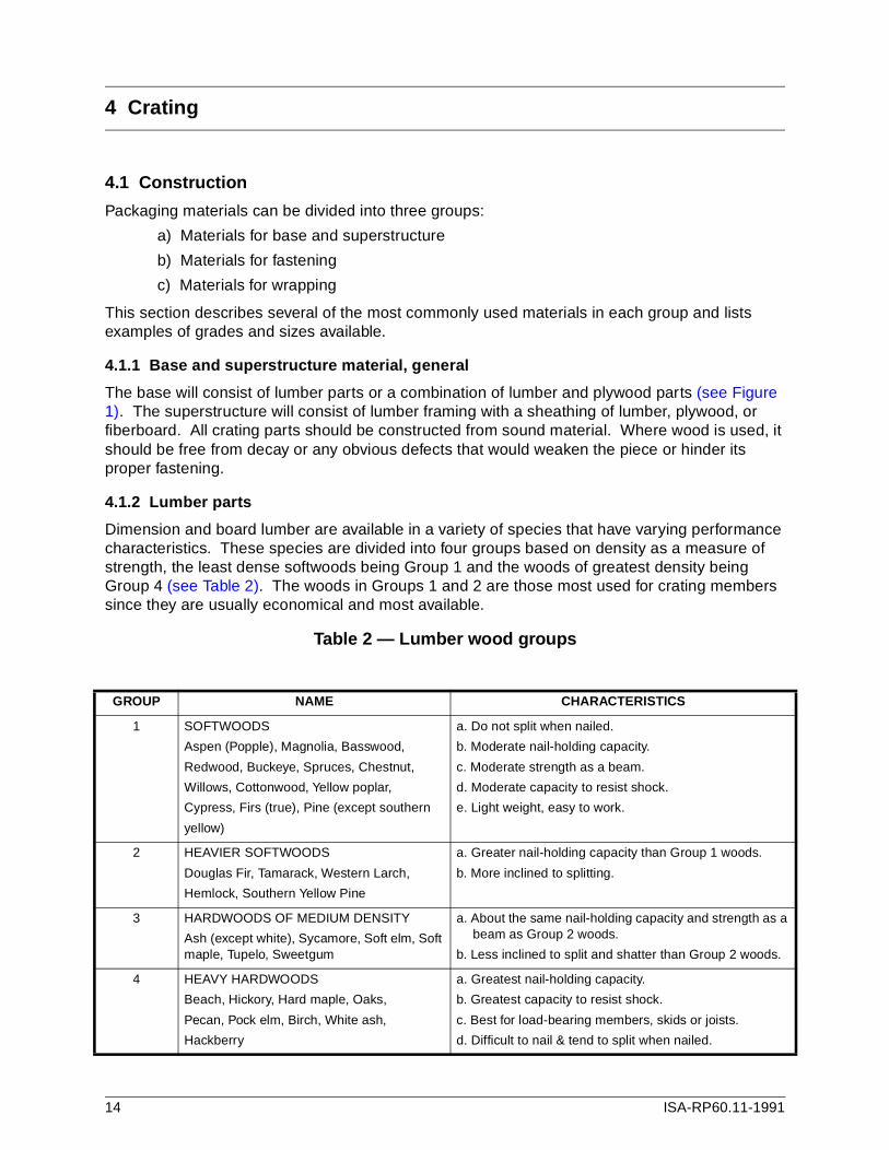
Dimension and board lumber are available in a variety of species that have varying performance characteristics. These species are divided into four groups based on density as a measure of strength, the least dense softwoods being Group 1 and the woods of greatest density being Group 4 (see Table 2). The woods in Groups 1 and 2 are those most used for crating members since they are usually economical and most available.
Table 2 — Lumber wood groups
GROUP NAME CHARACTERISTICS
1 SOFTWOODS
Aspen (Popple), Magnolia, Basswood,
Redwood, Buckeye, Spruces, Chestnut,
Willows, Cottonwood, Yellow poplar,
Cypress, Firs (true), Pine (except southern
yellow)
a. Do not split when nailed.
b. Moderate nail-holding capacity.
c. Moderate strength as a beam.
d. Moderate capacity to resist shock.
e. Light weight, easy to work.
2 HEAVIER SOFTWOODS
Douglas Fir, Tamarack, Western Larch,
Hemlock, Southern Yellow Pine
a. Greater nail-holding capacity than Group 1 woods.
b. More inclined to splitting.
3 HARDWOODS OF MEDIUM DENSITY
Ash (except white), Sycamore, Soft elm, Soft maple, Tupelo, Sweetgum
a. About the same nail-holding capacity and strength as a beam as Group 2 woods.
b. Less inclined to split and shatter than Group 2 woods.
4 HEAVY HARDWOODS
Beach, Hickory, Hard maple, Oaks,
Pecan, Pock elm, Birch, White ash,
Hackberry
a. Greatest nail-holding capacity.
b. Greatest capacity to resist shock.
c. Best for load-bearing members, skids or joists.
d. Difficult to nail & tend to split when nailed.
14 ISA-RP60.11-1991

Figure 1 — Crating type 1, open, base only
4.1.3 Plywood parts
For most standard crating purposes one plywood thickness and grade will perform the structural, durability, and covering functions. This is 3/8-in. (9.5-mm) thick APA grade — trademarked C-D plywood with exterior glue. C-D plywood in this thickness will be stamped with one of three index numbers (16/0, 20/0, 24/0), which are used in general building. Any one of these is suitable for
ISA-RP60.11-1991 15
crate construction. While the 3/8-in. thickness is general for crates (up to 10,000 pounds (4500 kg) product weight), there are situations that may require thicker plywood: where pilferage is a problem, 1/2-in. (12.5-mm) or heavier plywood on the top is a definite deterrent; where exceptionally rough or abusive handling can be expected, use 1/2-in. (12.5-mm) thickness all around; for large or unusually shaped crates, it may be necessary to space struts or other vertical members 4 feet (1220 mm) on center rather than the recommended 2 feet (610 mm) on center. When strut spacing exceeds 2 feet (610 mm), 1/2-in. (12.5-mm) thick (minimum) plywood should be used.
4.1.4 Fiberboard parts
Fiberboard provides many of the same protective benefits as wood sheathing but is lighter in weight. It is available in double-faced single-wall stock, double-wall stock, and triple-wall corrugated structural material. Where large containers are involved, the preferred material is triple-wall structural fiberboard, 9/16-in. (14.3-mm) nominal thickness, weather-resistant Class 2 consisting of waterproof-type adhesive and water-resistant outer facing. This material can be scored, folded, and formed into a self-supporting sleeve that can be slipped over the properly mounted product and fastened to a wooden skid. It is also available in sheets that can be fastened to the superstructure frame members using staples or special nailing clips that are available from the fiberboard manufacturer.
4.1.5 Lumber dimensions
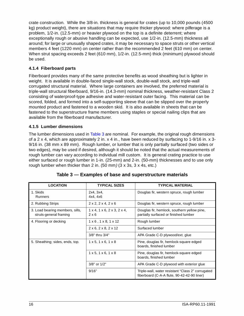
The lumber dimensions used in Table 3 are nominal. For example, the original rough dimensions of a 2 x 4, which are approximately 2 in. x 4 in., have been reduced by surfacing to 1-9/16 in. x 3-9/16 in. (38 mm x 89 mm). Rough lumber, or lumber that is only partially surfaced (two sides or two edges), may be used if desired, although it should be noted that the actual measurements of rough lumber can vary according to individual mill custom. It is general crating practice to use either surfaced or rough lumber in 1-in. (25-mm) and 2-in. (50-mm) thicknesses and to use only rough lumber when thicker than 2 in. (50 mm) (3 x 3s, 3 x 4s, etc.)
Table 3 — Examples of base and superstructure materials
LOCATION TYPICAL SIZES TYPICAL MATERIAL
1. Skids Runners
2x4, 3x4, 4x4, 4x6
Douglas fir, western spruce, rough lumber
2. Rubbing Strips 2 x 2, 2 x 4, 2 x 6 Douglas fir, western spruce, rough lumber
3. Load bearing members, sills, struts-general framing
1 x 4, 1 x 6, 2 x 3, 2 x 4,2 x 6
Douglas fir, hemlock, southern yellow pine, partially surfaced or finished lumber
4. Flooring or decking 1 x 6 , 1 x 8, 1 x 12 Rough lumber
2 x 6, 2 x 8, 2 x 12 Surfaced lumber
3/8” thru 3/4” APA Grade C-D plywood/ext. glue
5. Sheathing; sides, ends, top. 1 x 5, 1 x 6, 1 x 8 Pine, douglas fir, hemlock-square edged boards, finished lumber
1 x 5, 1 x 6, 1 x 8 Pine, douglas fir, hemlock-square edged boards, finished lumber
3/8” or 1/2” APA Grade C-D plywood with exterior glue
9/16” Triple-wall, water resistant “Class 2” corrugated fiberboard (C-A-A flute, 90-42-42-90 liner)
16 ISA-RP60.11-1991

4.1.6 Fastening materials, general
The most common fasteners used in crate construction are nails, lag screws, bolts, and steel strapping. Only new material should be used and should include a plating or coating, which will increase holding power and also provide protection from rusting during shipping and storage period.
4.1.7 Nails
The three types most used for crating purposes are smooth, cement coated or galvanized, and deformed shank. A good general rule to follow is that smooth nails (box or common) should be used when they are to be clinched. When nails are not clinched, the other types should be used because of their greater holding power, especially where softwood lumber is used. Where possible, the nail should be driven through the sheathing into the framing member and be long enough to penetrate at least 2 in. (50 mm) into the framing member. When sheathing is fastened to a 1-in. (25-mm) framing member, the nails should protrude at least 1/2 in. (12 mm) and be clinched.
4.1.8 Lag screws
Lag screws may be used to fasten sides to base, decking to skid, and contents to base. They are particularly useful when it is intended that the crate be disassembled and reused. They have excellent direct withdrawal and lateral resistance and are often used where high stresses can occur in handling. A plain flat washer or other reinforcing device should be used under the head of each lag screw. Penetration into the second member should be between 7 and 10 times the shank diameter of the lag screw. The diameter may be selected based on the size of the skid or fastening member used. Lag screws of 1/4-in. and 5/16-in. (6-mm and 8-mm) diameter are used on small crates with 2-in. (50-mm) members. Accordingly, larger lag screws are used where thicker skid members are present (see Table 4).
Table 4 — Lag screws
4.1.9 Bolts
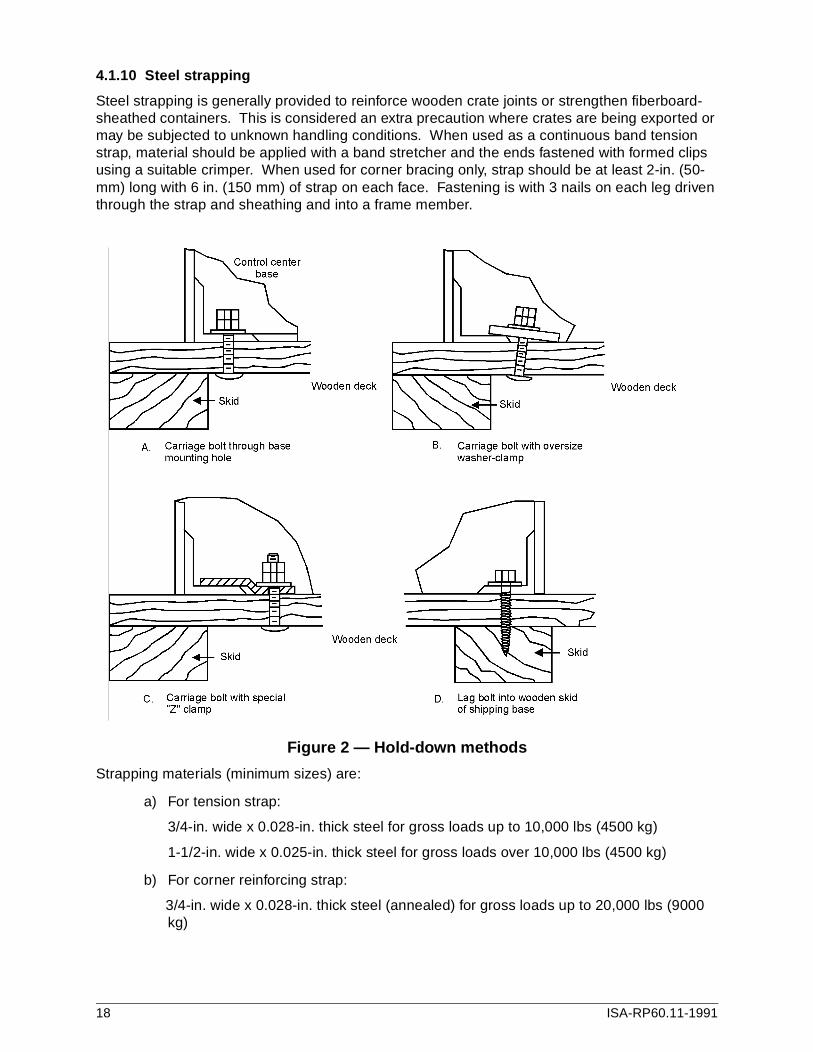
Bolts are primarily used for fastening large base members, anchoring contents to base, and in holding blocking in place. Select bolt diameter and length to suit the size of the member being attached or to fit the mounting hole provided in the unit being anchored. Most commonly used are 3/8 in., 1/2-in., and 5/8-in. (9.5-mm, 12.5-mm, and 16-mm) diameter carriage bolts. Fasten the bolt to contents using a lock nut, lock washers, or suitable thread-locking compound. For examples of bolt fastening methods, see Figure 2.
NOMINAL FACE WIDTH OF MEMBER (in.)
LAG SCREW DIAMETER (in.)
LEAD HOLE DIAMETER (in.)
DEPTH OF PENETRATION (in.)
2 (50 mm) 1/4
5/16
3/16
1/4
2 (50 mm)
2 (50 mm)
3 (76 mm) 3/8 1/4 2 (50 mm)
4 (100 mm) 1/2 3/8 2-1/2 (64 mm)
6 (150 mm) or wider 5/8
3/4
3/8
1/2
3 (76 mm)
3-1/2 (90 mm)
NOTE: Penetration is the minimum depth of each lag srew should penetrate into the receiving member. The recommended minimum length of lag screw for any application can be obtained by adding the thickness of the first member and the depth of penetration.
ISA-RP60.11-1991 17
4.1.10 Steel strapping
Steel strapping is generally provided to reinforce wooden crate joints or strengthen fiberboard-sheathed containers. This is considered an extra precaution where crates are being exported or may be subjected to unknown handling conditions. When used as a continuous band tension strap, material should be applied with a band stretcher and the ends fastened with formed clips using a suitable crimper. When used for corner bracing only, strap should be at least 2-in. (50-mm) long with 6 in. (150 mm) of strap on each face. Fastening is with 3 nails on each leg driven through the strap and sheathing and into a frame member.
Figure 2 — Hold-down methods
Strapping materials (minimum sizes) are:
a) For tension strap:
3/4-in. wide x 0.028-in. thick steel for gross loads up to 10,000 lbs (4500 kg)
1-1/2-in. wide x 0.025-in. thick steel for gross loads over 10,000 lbs (4500 kg)
b) For corner reinforcing strap:
3/4-in. wide x 0.028-in. thick steel (annealed) for gross loads up to 20,000 lbs (9000 kg)
18 ISA-RP60.11-1991
4.1.11 Wrapping material
Wrapping provides protection that cannot be obtained by crating alone. Where completely enclosed crating is used, there will be some protection from weather and dust. However, where open crating is used, wrapping must be included to provide this protection. In some cases, even with enclosed crating, wrapping may be desirable to protect the contents from dust or moisture while in storage. General rules for use of wrappings are as follows:
a) Plain, untreated kraft papers should be used only when a completely enclosed crate is provided.
b) Paper wrapping used in conjunction with open-type crating should be a heavy duty kraft paper that is waterproofed either by a plastic coating or by an asphaltic adhesive barrier applied between two layers of paper. If outside storage is a possibility, these papers should also include a reinforcement to provide extra strength.
c) Polyethylene sheet wrapping should not be used unless a desiccant is also provided. See Section 4.4, Humidity protection.
d) When the method of transportation is likely to subject material to the weather or if storage conditions at the job site are unknown, consider humidity protection (see Section 4.4).
e) When joining wrapper sheets, use a sealing tape that has an adhesive with high holding power, capable of sticking to treated and coated surfaces. Tape used should be suitable for outdoor exposure and designed for heavy duty packaging and splicing applications.
4.2 Types of crating
4.2.1 Type 1 open
Base only (see Fig. 1 and Fig. 2). For limited use, generally when shipment is by moving van and receiving conditions at the job site are ideal. The control center must be protected during shipment and unloading by pads and quilts, usually furnished by the moving company. Supervision by the control center manufacturer during the packing and loading operation is recommended.
4.2.2 Type 2 general-purpose
Base with open superstructure (see Fig.3). Contents must be covered with heavy water-resistant wrapping. This crating is suitable for most domestic shipments but is not recommended where considerable outdoor exposure is anticipated.
4.2.3 Type 2S general-purpose, humidity protected
Same as Type 2 with the addition of a desiccant or volatile corrosion inhibitor (VCI) material for short-term indoor storage (up to 3 months). Refer to Section 4.4, Humidity protection.
4.2.4 Type 3 enclosed
Base with completely covered superstructure (see Fig. 4 and Fig. 5) Superstructure consists of wood frame members sheathed with matched boards, plywood, or triple-wall corrugated fiberboard sheets. Framing is not required if a fiberboard sleeve or 5-panel wraparound and fitted cap are used (see Fig. 6). This crating is suitable for all domestic shipments and is recommended where considerable outdoor exposure is anticipated or where the extent of outdoor exposure is unknown.
ISA-RP60.11-1991 19

Figure 3 — Crating type 2, general-purpose
Figure 4 — Crating types 3 & 4, enclosed, board lumber
20 ISA-RP60.11-1991

4.2.5 Type 3S enclosed, humidity protected
Same as Type 3 with the addition of a desiccant or VCI material for long-term indoor or outdoor storage (up to 18 months). Refer to Section 4.4, Humidity protection.
4.2.6 Type 4 export
Base with completely covered superstructure (see Fig. 4 and Fig. 5). This crating is similar to Type 3 crating but must also include a waterproof paper covering of the contents or a waterproof paper lining of the inside crate walls, and steel band reinforcement must be provided. Depending on size, diagonal sidewall bracing and structural reinforcement for sling and grab-hook handling may be necessary.
Export crating must be constructed to provide maximum protection from all weather elements and must have sufficient strength to allow for stacking and for handling by all common lifting means. Marking the crate to show proper areas for handling is recommended (see Section 4.5).
Figure 5 — Crating types 3 & 4, enclosed, plywood
4.2.7 Type 4S export, humidity protected
Same as Type 4 with the addition of a desiccant or VCI material for long-term indoor or outdoor storage (up to 18 months). Refer to Section 4.4, Humidity Protection.
4.2.8 Dust-tight construction
Type 3 through Type 4S crating is considered dust-tight if constructed using plywood or fiberboard sheathing with material joints properly fastened and located on the center of a strut or frame member or, where size permits, using a formed fiberboard sleeve and cap. Example: Specify Type 3 Enclosed, Dust-Tight.
ISA-RP60.11-1991 21

NOTE: Crating diagrams are provided to illustrate general methods only. All construction details not shown should follow good commercial building practice for heavy duty service.
4.3 Selection of crate
Selection of crate must be based on all conditions that the unit will be exposed to from the start of shipment until it is set in place at the ultimate location. Table 5 shows the minimum crating required to suit various shipping and handling conditions. Make a selection from each category to fulfill the anticipated condition. From this selection, choose the type that provides protection for the most adverse condition.Example—Carrier (C) Flatbed trailer Type 3Storage (E) Job site, unprotected Type 3SUnloading (A) Forklift Type 1Location (B1) Above level Type 2Access (B) Obstructed Type 2
Since the most adverse condition is unprotected storage at the job site, choose crating Type 3S. Always use a "Type S" crate when adverse storage conditions are anticipated or if storage conditions are unknown.
4.4 Humidity protection
Damage to the control center finish and to its electrical and electronic components can occur when the product is stored in an uncontrolled environment for even a short period of time. Unless it can be absolutely assured that, when received at the job site, the control center will be immediately unloaded and placed in a dry, finished control room, humidity protection should be provided.
Two methods of providing humidity protection within the control center crate itself are:
a) use of desiccants (see 4.4.1 and 4.4.2); and
b) use of volatile corrosion inhibitors (VCI) (see 4.4.3 through 4.4.7).
4.4.1 Desiccants
A desiccant is a substance with a high moisture absorbing capacity that is used to prevent corrosion by absorbing the moisture from the air inside a package. The material is usually contained within cloth or paper bags but may also be packaged in specially designed sieve-like plastic and metal tubes and discs. Packaged desiccant is available in various sizes, by weight (in grams, ounces, and pounds) or in "units." A "unit" is defined as that weight of desiccant that will absorb at least 3 grams of water at 20% relative humidity and at a temperature of 25° C (77° F).
NOTE: Above 40% R.H. is considered the danger zone for metal corrosion.
The desiccant is placed inside the control center, which must then be sealed with a moisture-impervious barrier. When all proper precautions have been taken to provide the correct packaging, eliminate any initial source of dampness and furnish the proper amount of desiccant. The protection period should be approximately 18 months.
22 ISA-RP60.11-1991
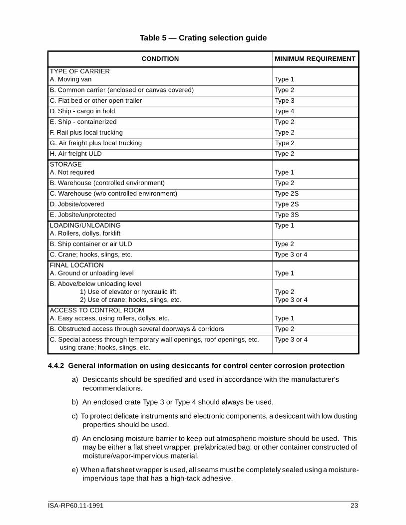
Table 5 — Crating selection guide
4.4.2 General information on using desiccants for control center corrosion protection
a) Desiccants should be specified and used in accordance with the manufacturer's recommendations.
b) An enclosed crate Type 3 or Type 4 should always be used.
c) To protect delicate instruments and electronic components, a desiccant with low dusting properties should be used.
d) An enclosing moisture barrier to keep out atmospheric moisture should be used. This may be either a flat sheet wrapper, prefabricated bag, or other container constructed of moisture/vapor-impervious material.
e) When a flat sheet wrapper is used, all seams must be completely sealed using a moisture-impervious tape that has a high-tack adhesive.
CONDITION MINIMUM REQUIREMENT
TYPE OF CARRIERA. Moving van Type 1
B. Common carrier (enclosed or canvas covered) Type 2
C. Flat bed or other open trailer Type 3
D. Ship - cargo in hold Type 4
E. Ship - containerized Type 2
F. Rail plus local trucking Type 2
G. Air freight plus local trucking Type 2
H. Air freight ULD Type 2
STORAGEA. Not required Type 1
B. Warehouse (controlled environment) Type 2
C. Warehouse (w/o controlled environment) Type 2S
D. Jobsite/covered Type 2S
E. Jobsite/unprotected Type 3S
LOADING/UNLOADINGA. Rollers, dollys, forklift
Type 1
B. Ship container or air ULD Type 2
C. Crane; hooks, slings, etc. Type 3 or 4
FINAL LOCATIONA. Ground or unloading level Type 1
B. Above/below unloading level1) Use of elevator or hydraulic lift2) Use of crane; hooks, slings, etc.
Type 2Type 3 or 4
ACCESS TO CONTROL ROOMA. Easy access, using rollers, dollys, etc. Type 1
B. Obstructed access through several doorways & corridors Type 2
C. Special access through temporary wall openings, roof openings, etc. using crane; hooks, slings, etc.
Type 3 or 4
ISA-RP60.11-1991 23

f) Any dunnage, such as packing, pads, liners, wood blocking, or other hygroscopic cushioning or supporting materials, used inside the barrier contains moisture that must be compensated for by calculated quantities of desiccant. Therefore, dunnage used inside the moisture barrier should be kept to a reasonable minimum and packaging materials should be kept dry.
g) When packing with desiccant, the user should bear in mind that it will rapidly absorb moisture from the air. Care must be taken when transferring bags of desiccant from their shipping container to the package, and the barrier should be closed as quickly as possible.
h) Surfaces of the packaged material should be cleaned, except for normal lubricants or preservative oils, and free of any liquid film of water. Package interior must be free of any entrapped water.
Figure 6 — Crating type 3, enclosed, fiberboard
4.4.3 Volatile corrosion inhibitors (VCI)
VCI are special packaging papers, blocks, plastics, or other materials that are impregnated with or coated with a rust-inhibiting chemical. The chemical forms a vapor that is invisible, non-toxic, nonhazardous, and rust-inhibiting. The vapor saturates the atmosphere within the package. Depending on the type of chemical used, corrosion of metal parts is controlled in one of two ways:
a) By neutralizing the corrosive action of water and oxygen. Corrosion does not occur if the water contains the dissolved chemical, even if the water is in direct contact with bare steel or some other metal the chemical is designed to protect.
24 ISA-RP60.11-1991
b) By depositing a water-repellant film on the metal surfaces. This prevents corrosion by keeping water from direct contact with the metal surface.
VCI are designed for specific types of protection. Some are intended for use with ferrous metals only, others for certain types or a combination of types of nonferrous metals, and still others are suitable for use where both ferrous and nonferrous metals are present. Control centers, which contain a mix of various materials, should be protected by a VCI designed for use where both ferrous and nonferrous metals are present. Two types of products are available for this service:
a) Corrosion inhibitor blocks
b) Corrosion inhibitor wrapping paper
Depending on the type of corrosion inhibitor used, the type of crating, and the surrounding moisture conditions, the protection period can range from 6 months to 5 years. For maximum protection, the use of additional vapor barrier wrapping and fully enclosed crating is recommended.
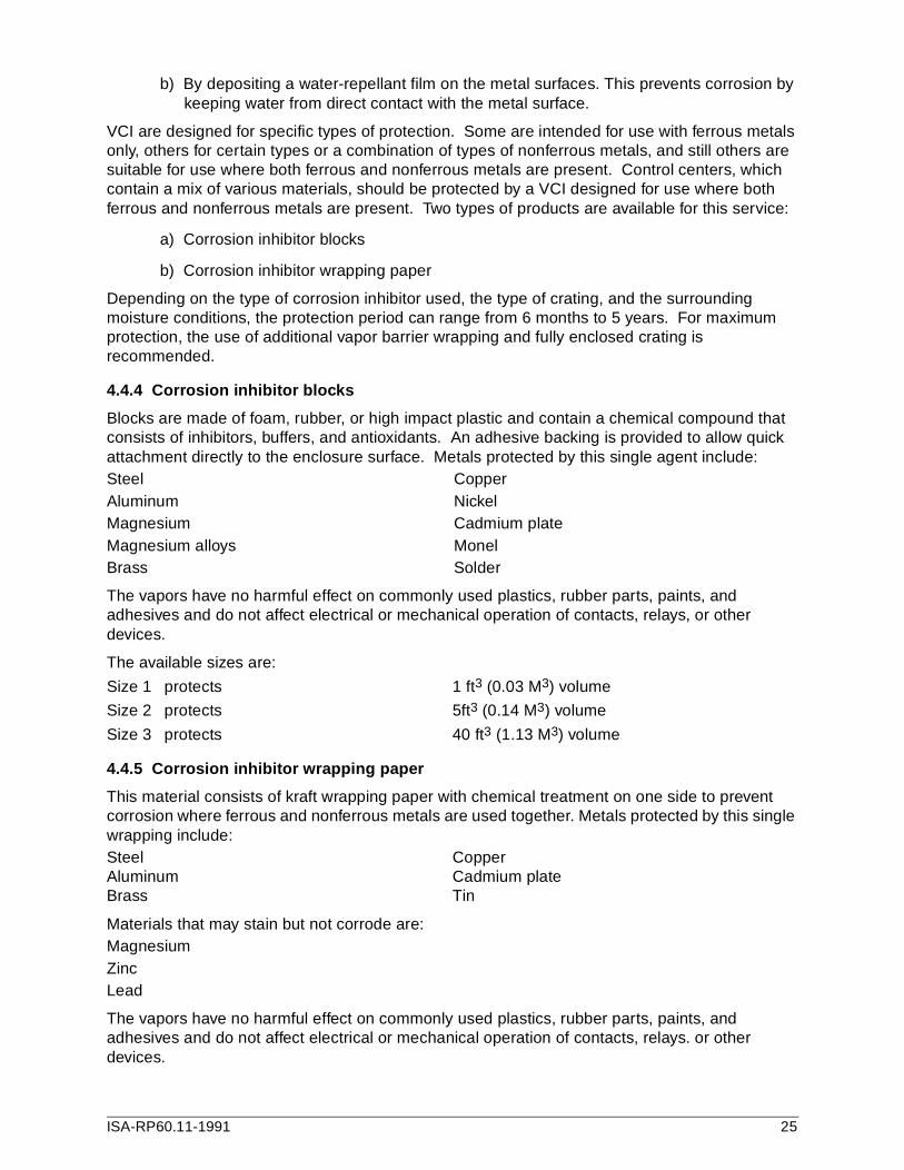
4.4.4 Corrosion inhibitor blocks
Blocks are made of foam, rubber, or high impact plastic and contain a chemical compound that consists of inhibitors, buffers, and antioxidants. An adhesive backing is provided to allow quick attachment directly to the enclosure surface. Metals protected by this single agent include:Steel CopperAluminum NickelMagnesium Cadmium plateMagnesium alloys MonelBrass Solder
The vapors have no harmful effect on commonly used plastics, rubber parts, paints, and adhesives and do not affect electrical or mechanical operation of contacts, relays, or other devices.
The available sizes are:
Size 1 protects 1 ft3 (0.03 M3) volume
Size 2 protects 5ft3 (0.14 M3) volume
Size 3 protects 40 ft3 (1.13 M3) volume
4.4.5 Corrosion inhibitor wrapping paper
This material consists of kraft wrapping paper with chemical treatment on one side to prevent corrosion where ferrous and nonferrous metals are used together. Metals protected by this single wrapping include:Steel CopperAluminum Cadmium plateBrass Tin
Materials that may stain but not corrode are:MagnesiumZincLead
The vapors have no harmful effect on commonly used plastics, rubber parts, paints, and adhesives and do not affect electrical or mechanical operation of contacts, relays. or other devices.
ISA-RP60.11-1991 25
Wrapping is supplied in rolls (width and length vary with the manufacturer) and is available in two grades:
a) Plain kraft paper plus VCI treated on one side
b) Waterproof kraft paper plus VCI treated on one side, with a waterproofing wax barrier on other side, or with an asphaltic adhesive barrier applied between the treated paper and an outer layer of paper.
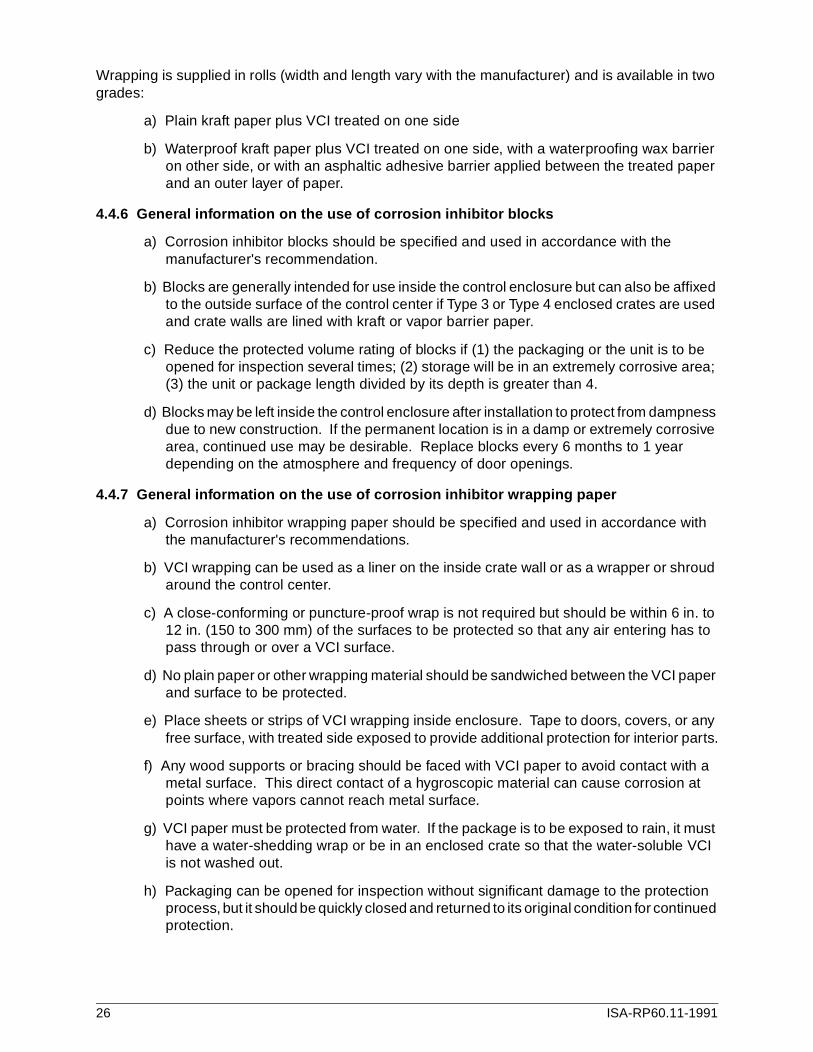
4.4.6 General information on the use of corrosion inhibitor blocks
a) Corrosion inhibitor blocks should be specified and used in accordance with the manufacturer's recommendation.
b) Blocks are generally intended for use inside the control enclosure but can also be affixed to the outside surface of the control center if Type 3 or Type 4 enclosed crates are used and crate walls are lined with kraft or vapor barrier paper.
c) Reduce the protected volume rating of blocks if (1) the packaging or the unit is to be opened for inspection several times; (2) storage will be in an extremely corrosive area; (3) the unit or package length divided by its depth is greater than 4.
d) Blocks may be left inside the control enclosure after installation to protect from dampness due to new construction. If the permanent location is in a damp or extremely corrosive area, continued use may be desirable. Replace blocks every 6 months to 1 year depending on the atmosphere and frequency of door openings.
4.4.7 General information on the use of corrosion inhibitor wrapping paper
a) Corrosion inhibitor wrapping paper should be specified and used in accordance with the manufacturer's recommendations.
b) VCI wrapping can be used as a liner on the inside crate wall or as a wrapper or shroud around the control center.
c) A close-conforming or puncture-proof wrap is not required but should be within 6 in. to 12 in. (150 to 300 mm) of the surfaces to be protected so that any air entering has to pass through or over a VCI surface.
d) No plain paper or other wrapping material should be sandwiched between the VCI paper and surface to be protected.
e) Place sheets or strips of VCI wrapping inside enclosure. Tape to doors, covers, or any free surface, with treated side exposed to provide additional protection for interior parts.
f) Any wood supports or bracing should be faced with VCI paper to avoid contact with a metal surface. This direct contact of a hygroscopic material can cause corrosion at points where vapors cannot reach metal surface.
g) VCI paper must be protected from water. If the package is to be exposed to rain, it must have a water-shedding wrap or be in an enclosed crate so that the water-soluble VCI is not washed out.
h) Packaging can be opened for inspection without significant damage to the protection process, but it should be quickly closed and returned to its original condition for continued protection.
26 ISA-RP60.11-1991

4.5 Marking for shipment and storage
Marking is the application of addresses, contract numbers, item description, size and weight, and any special handling information, which is stamped, painted, or stenciled on a crate for identification during shipping, handling, and storage. Most control center crating will require some marking to help in proper delivery. Markings may not be necessary, or will be minimal, when shipment is by exclusive moving van or truck or is within a land/sea/air container, as these are door-to-door services.
NOTE: Equipment being shipped on government contracts should be marked in accor-dance with MIL-STD-129 (latest revision) or other document as specified by the procuring agency.
4.5.1 General requirements for markings
Markings shall be sized, located, and applied in accordance with good commercial shipping practice for the particular mode of transportation being used. Markings shall consist of required markings (see 4.5.2), handling instructions (see 4.5.3), and precautionary markings (see 4.5.4).
Proper address information, case marks, and other identification data desired by the purchaser shall be supplied as part of the bid documents, purchase order, or contract. The manufacturer or shipper shall provide necessary special handling and precautionary markings to insure proper handling and storage of the equipment.
4.5.2 Required markings
All data listed are required for overseas shipment. Data marked (NR) means "Not Required" for domestic shipments.
a) Destination (consignee name and address)
b) Return address (consignor name and address)
c) Port of entry (NR)
d) Purchase order no. and/or contract no.
e) Letter of credit no. (NR)
f) Any other identification required by purchaser
g) Weight in pounds and kilograms:
Gross weightNet weight (NR)Tare weight (NR)
h) Overall dimensions in inches and meters (NR)
i) Volume in cubic feet and cubic meters (NR)
j) Item identification numbersExample 1: 1 crate (or box, carton, etc.) Example 2: Box No. 5Example 3: Box 1 of 5 (or 1/5)
ISA-RP60.11-1991 27

4.5.3 Handling instructions
The need for special handling instructions shall be determined by the manufacturer or shipper depending on the nature of contents and construction of the crate and skid. These markings should be applied in accordance with standard shipping practice and shall not interfere with the required markings. The following are several examples of special markings:
ARROWS—Mark an arrow with or without the words UP or TOP. Used where the safety of the contents requires storing or stacking with top up.
SLING HERE—Use a bold mark in conjunction with the legend to denote structural points suitable for locating slings. If a sling should not be used, mark: DO NOT SLING.
CENTER OF BALANCE —Use a bold mark in conjunction with the legend to indicate the center of balance on unbalanced crates and crates over 10 feet (3 m) long.
USE NO HOOKS—Use this legend only or in conjunction with a hook symbol and superimposed "x" to inform that contents or crate are susceptible to damage by use of hooks.
LOAD BEARING AREA AND FORKLIFT AREA —Use these markings and legends to denote proper handling areas so that the crate and contents are not subject to damage caused by bending and twisting from uneven container stresses and strains.
4.5.4 Precautionary markings
The need for precautionary markings shall be determined by the manufacturer or shipper depending on the nature of the contents. When applicable, locate these markings on one side and one end of crate using red uppercase lettering approximately 1 in. (25 mm) high. Do not locate so as to interfere with the required markings, and do not use indiscriminately. The following are examples of precautionary markings for a control center:
PACKAGED WITH DESICCANTDO NOT OPEN UNTIL READYFOR USE OR INSPECTION
PACKAGED WITH CORROSION INHIBITORDO NOT OPEN UNTIL READYFOR USE OR INSPECTION
DELICATE ELECTRONIC ANDELECTRICAL EQUIPMENTHANDLE WITH CARE
STORE IN COOL, DRY LOCATIONAWAY FROM WORK AREASAWAY FROM WELDING AREAS
IMPORTANTREFER TO MANUFACTURER'SINSTRUCTIONS BEFORE UNCRATING
IMPORTANT DO NOT SHAKE, JOLT, DROPVIBRATION MONITOR INSIDE
IMPORTANTDO NOT EXPOSE TO TEMP. OVER ( ) °F.TEMPERATURE MONITOR INSIDE
28 ISA-RP60.11-1991

5 Shipping
5.1 Shipping modes
Unless otherwise specified, the control center manufacturer will make shipping arrangements based on the size of the piece being shipped, the destination, the delivery schedule, and the cost. If the buyer prefers a particular mode of transportation, this should be so stated in specifications, bid documents, purchase orders, etc. The size of the control center will be one of the biggest factors in determining what shipping equipment can be used. Control centers designed in sections and those that utilize modular construction can be shipped by any conventional shipping equipment. But control centers constructed as a single large unit may pose a problem in locating special shipping equipment.
Since the need for special equipment results in higher shipping costs and possible delays while awaiting the availability of such equipment, it is advisable to design control centers to fit the most common shipping vehicles. As a general guide for sizing control centers, approximate dimensions of common shipping equipment are provided in Figures 7, 8, and 9.
Figure 7 — Trailer and container dimensions
ISA-RP60.11-1991 29

Figure 8 — Electronics van dimensions
5.1.1 General information
5.1.1.1 Standard truck equipment includes conventional closed-top trailers and open-top, canvas-covered trailers. Open-top trailers may be necessary where extra high control centers must be loaded and unloaded by crane.
5.1.1.2 When the size of the control center is such that standard trailers cannot be used, special trailers are available. Some common carriers and other companies classified as heavy haulers can supply flatbed, drop-bed, and low-boy trailers. This equipment is not always easily obtainable; therefore, arrangements should be made well in advance to avoid shipping delays. Unless the shipping distance is local, enclosed crating Type 3S should be used.
5.1.1.3 Some moving van lines specialize in handling high-value products. The higher rate for this mode of shipment is partially offset due to the elimination of costly crating, less possibility of damage because of less handling, and the ability to maintain exact delivery schedules.
The control center is protected by necessary padding provided by the van company, and specialized handling is done by people accustomed to moving household furniture and electronic equipment. The standard van is enclosed, has access at the rear and both sides, and its floor is nearly two feet closer to the ground than in a standard trailer, providing easier loading and
30 ISA-RP60.11-1991

unloading. In addition to the standard van, units are available with air-ride suspension, hydraulic tailgate, climate control, and other special handling features.
5.1.1.4 Conventional ship transportation requires special crating for extra protection from excessive handling, stacking, and outside exposure during loading and unloading. Crating requirements and the possibility of damage are greatly reduced by using modular containers. The container is basically a standard trailer body. This body is detachable from its road chassis and is designed to be loaded and stacked aboard special container-handling vessels. Since the control center remains in one container from the time it is loaded until it is delivered to the final destination, crating for export is not required.
5.1.1.5 Airline freight companies provide a container service called ULD (Unit Load Devices). When the size of the control center permits, this device can be loaded at the manufacturer's plant, sealed, and not reopened until arrival at the final destination. No crating or minimum crating Type 1 (see 4.2) is sufficient. For examples of ULD, see Figure 9.
Figure 9 — Aircraft unit load devices
5.1.2 Shipping mode comparison
The different shipping modes provide various advantages and disadvantages in cost, handling, crating, etc. Table 6 is a quick reference guide in comparing the shipping modes.
Explanation of Table 6 data:
ISA-RP60.11-1991 31
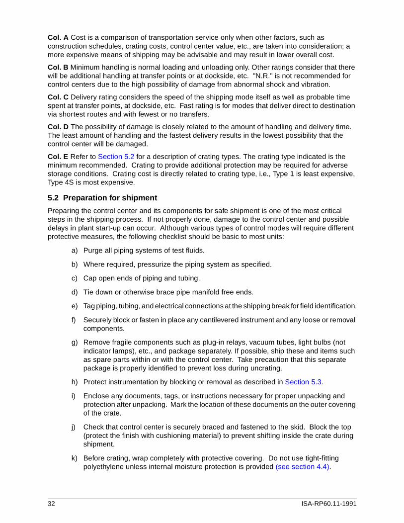
Col. A Cost is a comparison of transportation service only when other factors, such as construction schedules, crating costs, control center value, etc., are taken into consideration; a more expensive means of shipping may be advisable and may result in lower overall cost.
Col. B Minimum handling is normal loading and unloading only. Other ratings consider that there will be additional handling at transfer points or at dockside, etc. "N.R." is not recommended for control centers due to the high possibility of damage from abnormal shock and vibration.
Col. C Delivery rating considers the speed of the shipping mode itself as well as probable time spent at transfer points, at dockside, etc. Fast rating is for modes that deliver direct to destination via shortest routes and with fewest or no transfers.
Col. D The possibility of damage is closely related to the amount of handling and delivery time. The least amount of handling and the fastest delivery results in the lowest possibility that the control center will be damaged.
Col. E Refer to Section 5.2 for a description of crating types. The crating type indicated is the minimum recommended. Crating to provide additional protection may be required for adverse storage conditions. Crating cost is directly related to crating type, i.e., Type 1 is least expensive, Type 4S is most expensive.
5.2 Preparation for shipment
Preparing the control center and its components for safe shipment is one of the most critical steps in the shipping process. If not properly done, damage to the control center and possible delays in plant start-up can occur. Although various types of control modes will require different protective measures, the following checklist should be basic to most units:
a) Purge all piping systems of test fluids.
b) Where required, pressurize the piping system as specified.
c) Cap open ends of piping and tubing.
d) Tie down or otherwise brace pipe manifold free ends.
e) Tag piping, tubing, and electrical connections at the shipping break for field identification.
f) Securely block or fasten in place any cantilevered instrument and any loose or removal components.
g) Remove fragile components such as plug-in relays, vacuum tubes, light bulbs (not indicator lamps), etc., and package separately. If possible, ship these and items such as spare parts within or with the control center. Take precaution that this separate package is properly identified to prevent loss during uncrating.
h) Protect instrumentation by blocking or removal as described in Section 5.3.
i) Enclose any documents, tags, or instructions necessary for proper unpacking and protection after unpacking. Mark the location of these documents on the outer covering of the crate.
j) Check that control center is securely braced and fastened to the skid. Block the top (protect the finish with cushioning material) to prevent shifting inside the crate during shipment.
k) Before crating, wrap completely with protective covering. Do not use tight-fitting polyethylene unless internal moisture protection is provided (see section 4.4).
32 ISA-RP60.11-1991

ISA
-RP
60.11-199133
DAMAGE
E
CRATING
Low
Ave
rag
e
Hig
h
Exc
ess
ive
Typ
e 1
Typ
e 2
or
2S
Typ
e 3
or
3S
Typ
e 4
or
4S
•
• •
• •
• •
•
•
• •
• •
•
• •
• •
•
Table 6 — Comparison of shipping modes
SHIPPING MODE TYPE OF FREIGHT
A
COST
B
HANDLING
C
DELIVERY
D
Low
Mo
dera
te
Hig
h
Hig
hest
Min
imum
Ave
rag
e
Abo
ve A
vg.
N.R
.
Slo
w
Ave
rag
e
Abo
ve A
vg.
Fast
AIRLINE Unit load device • • • •
Std. cargo • • •
BARGE Piggy back trailer • • •
On deck • • •
MOVING VAN Shared load • • • •
Exclusive use • • • •
RAIL Piggy back trailer • • •
Freight car • • •
SHIP Containerized • • • •
In hold • • •
TRUCK Mixed freight • • •
Exclusive use • • • •

5.3 Instrument care
All instruments should be prepared for shipment in accordance with the manufacturer's recommendations. Where shipment of mounted instruments could cause damage or void the manufacturer's warranty, these instruments shall be removed after wiring and testing. All instruments removed for separate shipment shall be tagged with suitable identification to facilitate easy reassembly at the job site. If possible, these instruments should be repackaged in their original cartons, and any protective liners, fasteners, and cushioning materials should be returned to their original location.
All instruments remaining on the control center shall be checked to assure proper support and protection of removable and fragile parts. Provide cushioning material where necessary. Long cases not supported by a structural member should have temporary blocking and bracing to provide protection from jolting and vibration. All shipping stops and case locks should be engaged to prevent accidental jarring of the unit from its case. Protect glass windows and doors from shock and physical damage by covering them with fiberboard or other cushioning material. If tape is used to hold the doors closed, it shall not be applied directly to plastic windows.
5.4 FOB and insurance
When and where does title transfer from seller to buyer? Who pays transportation charges? Is the control center fully insured? These are some of the points that should be fully understood and agreed upon between buyer and seller before shipping occurs.
5.4.1 FOB (free on board)
A common transportation term, this is often vague and elusive to many buyers and transportation users. Courts have ruled as follows on the legal definition of the term:
The meaning of the words "free on board" is that the seller is to put the goods onboard at his own expense for the account of the person for whom they are shipped;delivery is made to and the goods are transported at the risk of the buyer from thetime when they are so put on board (Sparta Produce Exchange vs. Wilson, 223 Il-linois Appellate Court Reports 126).
Title of the shipment, along with the responsibility such title implies, passes from the seller to the buyer at the FOB point, and unless other arrangements are called for in the sales contract, court will assume that this was the intent of the parties.
The FOB terms also determine whether the seller or buyer will pay the transportation charges to the carrier. Generally, on an "FOB origin" shipment, the buyer is required to pay the transportation charges. On a "FOB destination" shipment, they are the responsibility of the seller. However, other arrangements can be provided for in the sales contract.
It is recommended that whenever the term FOB is used it be clarified with the addition of the name of the point (this can be a plant, warehouse, city, etc.) where the buyer is to take title. This clarification eliminates confusion as to the intent of the parties as to just where title is to be transferred from seller or buyer.
5.4.2 Insurance
Insurance during transportation is not regulated by federal or state agencies. Therefore, it is possible to find a wide range of coverage variations between the different modes of transportation and between various companies offering similar services. Since the shipper is obliged to exercise due care in the delivery of the product, the shipper must be aware of the coverage allowed by the selected carrier and should provide additional insurance, if necessary, for full coverage. The buyer should be aware of the insurance in effect when taking title, including storage insurance coverage in a warehouse or on the construction site.
34 ISA-RP60.11-1991

Normally, a carrier will allow a fixed amount of coverage per shipment or per pound of shipment. If the actual cash value of the control center is in excess of this amount, additional insurance coverage should be provided by the responsible party.
EXAMPLE: Control center wt. 1350 lbs (614 kg)Control center value $16,500.00Insurance allowed $8.00/lbTotal coverage if unitis lost or destroyed $10,800.00Additional insurancerequired $5,700.00
6 Handling methods
6.1 General
Handling of the control center begins upon completion of the fabricated enclosure and ends when the assembled and wired unit is finally bolted in place at the job site. Some of the handling points and methods used are described here to illustrate the importance of handling considerations in the design stage. For example: A single, very large control center will require the use of expensive special handling devices and possible provisions for special access openings in the building. A similar control center assembled from small sections, or modular units, can be easily handled by standard equipment through normal entry ways.
6.2 Handling methods
6.2.1 Handling in the manufacturing plant usually consists of:
a) an overhead crane via slings or chainfalls (see Section 6.3, Lifting eyes):
b) a forklift truck and hand forklifts; or
c) special dollys for painting and assembly.
6.2.2 Loading into truck or van
Loading at the manufacturing plant is usually from a dock or trailer floor. When this is the case, the unit can be easily loaded using:
a) a forklift truck and hand forklifts;
b) piano dollys; or
c) pipe rollers.
Where there is no loading platform, the unit may be handled using:
d) a trailer with a hydraulic tailgate;
e) a low van with long walk boards;
f) a large forklift truck with a lifting platform; or
ISA-RP60.11-1991 35
g) a crane vehicle via slings or chainfalls.
6.2.3 Handling in transit may be required at transfer points, at dockside, or into aircraft.
a) At truck terminals. loading and unloading will be at platform level using equipment listed for 6.2.2 (a), (b), and (c).
b) Dockside unloading will use a combination of all methods listed in 6.2.2. Loading into a ship's hold will be by crane via slings, nets, and grabhooks.
c) Loading into aircraft will be done by use of:
1) a forklift truck with lifting platform;
2) special hydraulic lift platforms; or
3) a crane vehicle via slings or chainfall.
6.2.4 Unloading at the job site will utilize some of the equipment described for loading in 6.2.2. In most cases, a platform at the proper elevation is not available. Therefore, the equipment listed in 6.2.2 (d) through (g) will most likely be required.
6.2.5 Lifting to upper floors
When the control room is located on a floor above ground level, means may include:
a) a service elevator if installed and rated for the weight of the control center;
b) a large forklift truck with lifting platforms; or
c) a crane vehicle via slings or chainfall.
6.2.6 Moving through a building
The building design should provide corridors and doorways of ample size to allow free movement of the control center into its final location. If this is not possible, a temporary wall or roof opening directly into the control room must be planned. Equipment for moving through a building and setting into the mounting pad includes:
a) hand operated forklifts;
b) forklift trucks;
c) piano dollies;
d) pipe rollers of various sizes;
e) hydraulic jacks; and
f) temporary overhead crane via sling or chainfall (see 6.3, Lifting eyes).
6.3 Lifting eyes
A control center enclosure may or may not be designed for handling by a lifting eye. If conditions at the job site are likely to require the use of lifting eyes, these should be included in the control center specifications so that the correct size and quantity can be furnished to safely handle the completely assembled unit. Shoulder-type eyebolts with a minimum safety factor of 4 should be used. In addition, the control center manufacturer should attach a warning tag with the following information:
a) Use spreader bar or lifting frame to obtain a straight upward pull.
36 ISA-RP60.11-1991
b) For proper weight distribution, all lifting eyes provided must be used.
c) When moving, do not lift more than one foot above floor level.
d) Move slowly to prevent excessive swinging.
e) Use stabilizing lines to reduce swinging motion.
f) Keep all personnel positioned at a safe distance during lifting.
6.4 Job site protection
The shipping crate can also provide protection of the control center during handling and storage at the job site. Job specifications, contract data, and crate markings should specify that the crate remain intact until final installation occurs.
6.5 Shipping monitors
When the nature of the control center is such that temperature control or handling method is critical, special monitors are available for installation within the control center before crating is complete. These special monitors include the following:
1) Accelerometers and impactometers. These items, sometimes referred to as "G" meters, will record the highest shock condition or that a specific impact was exceeded during shipment.
2) Thermal tabs and temperature-indicating paints and crayons. These items will record the highest temperature that the cargo was subjected to during shipment.
The use of this equipment should be marked on the outside of the crating (See 4.5.4, Precautionary markings).
7 Storage
7.1 General
Until the control center is finally installed in the environment for which it was originally designed, it may be subjected to various conditions that can produce extensive damage to the finish and to all the equipment it contains. To prevent this, job specifications should clearly state acceptable packaging and storage conditions.
7.2 Conditions that can be damaging
a) Long-term storage in a warehouse or other building where no climate control is provided, particularly where there is a possibility of exposure to corrosive vapors.
b) Long- or short-term storage at the job site in an enclosed shed, a covered area, or outdoors covered by a tarpaulin or polyethylene shroud.
c) Long- or short-term storage at the job site in a room of new concrete construction or freshly plastered walls.
d) Sitting on a dock waiting for overseas shipment or pickup after arrival.
e) Long distance shipment on a flatbed trailer or other open carrier.
ISA-RP60.11-1991 37
7.3 Conditions that will help protect the control center
a) Time the control center to be delivered when the control room is finished and the presence of moisture is unlikely.
b) Specify crating with humidity protection: Type 2S, 3S or 4S (see Section 4.2).
c) Size the control center to fit standard shipping modes and specify the use of an enclosed vehicle or shipping container.
d) Specify storage in a warehouse that has climate control.
8 Reference publications
1) Plywood Design Manual, Crating American Plywood Association T201,1974.
2) Plywood for Industrial Uses, American Plywood Association Z10, 1974.
3) "Fiberboard Packaging Information," from general data published by Tri-Wall Containers, Inc.
4) "Industrial Packaging Papers," from general data published by St. Regis Laminated & Coated Products Division.
5) "Packaging Desiccants Information," from general data published by Davison Chemical Division of W.R. Grace & Co.
6) "Volatile Corrosion Inhibitors, Papers and Blocks," from general information published by Cromwell Paper Company; Daubert Chemical Company; Hoffman Engineering Company; and Ludlow Packaging Corp.
7) "Crate Marking Information from Military Standard, Marking for Shipment & Storage," MIL-STD 129D, 1964.
8) "Special Handling of High Value Products," from general data published by Global Van Lines.
9) "Trailer & Container Information and Dimensions," from general data published by Sea-Land Corp.; United States Lines American Plywood Association S220-5/72.
10) "ULD Dimensions," from general data published by Air France Cargo.
11) The meaning of FOB from an article,"The Technicalities of FOB," Purchasing Magazine (date unknown).
12) Engineering Design in Wood, CSA CAN3-086.1-M84.
13) Poplar Plywood, CSA CAN3-0153-M80.
38 ISA-RP60.11-1991


Developing and promulgating technically sound consensus standards, recommended practices, and technical reports is one of ISA's primary goals. To achieve this goal the Standards and Practices Department relies on the technical expertise and efforts of volunteer commi ttee members, chairmen, and reviewers.
ISA is an American National Standards Institute (ANSI) accredited organization. ISA administers United States Technical Advisory Groups (USTAGs) and provides secretariat support for International Electrotechnical Commission (IEC) and International Organization for Standardization (ISO) committees that develop process measurement and control standards. To obtain additional information on the Society's standards program, please write:
ISAAttn: Standards Department67 Alexander DriveP.O. Box 12277Research Triangle Park, NC 27709
ISBN: 1-55617-229-X