crane control equipments,new delhi,crane spare parts
TRANSCRIPT


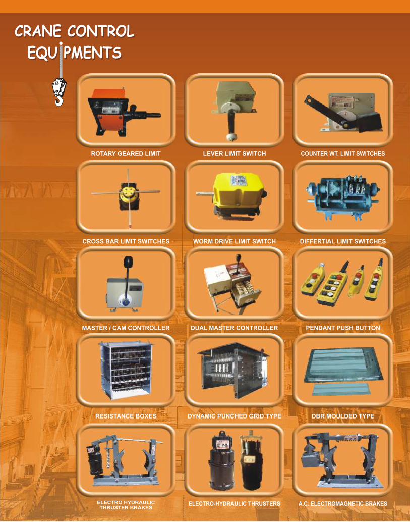
CRANE
CONTROL
EQUIPM
E TSN
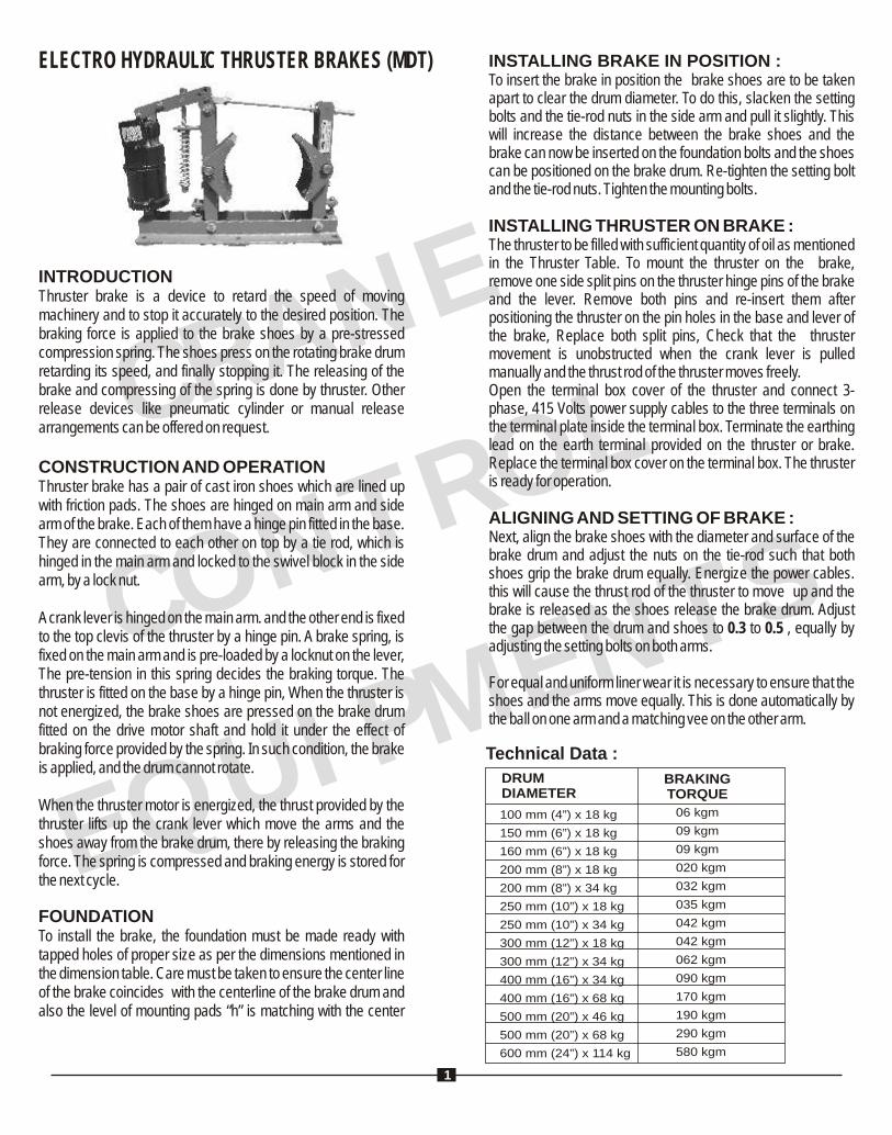
ELECTRO HYDRAULIC THRUSTER BRAKES (MDT)
INTRODUCTIONThruster brake is a device to retard the speed of moving machinery and to stop it accurately to the desired position. The braking force is applied to the brake shoes by a pre-stressed compression spring. The shoes press on the rotating brake drum retarding its speed, and finally stopping it. The releasing of the brake and compressing of the spring is done by thruster. Other release devices like pneumatic cylinder or manual release arrangements can be offered on request.
CONSTRUCTION AND OPERATIONThruster brake has a pair of cast iron shoes which are lined up with friction pads. The shoes are hinged on main arm and side arm of the brake. Each of them have a hinge pin fitted in the base. They are connected to each other on top by a tie rod, which is hinged in the main arm and locked to the swivel block in the side arm, by a lock nut.
A crank lever is hinged on the main arm. and the other end is fixed to the top clevis of the thruster by a hinge pin. A brake spring, is fixed on the main arm and is pre-loaded by a locknut on the lever, The pre-tension in this spring decides the braking torque. The thruster is fitted on the base by a hinge pin, When the thruster is not energized, the brake shoes are pressed on the brake drum fitted on the drive motor shaft and hold it under the effect of braking force provided by the spring. In such condition, the brake is applied, and the drum cannot rotate.
When the thruster motor is energized, the thrust provided by the thruster lifts up the crank lever which move the arms and the shoes away from the brake drum, there by releasing the braking force. The spring is compressed and braking energy is stored for the next cycle.
FOUNDATIONTo install the brake, the foundation must be made ready with tapped holes of proper size as per the dimensions mentioned in the dimension table. Care must be taken to ensure the center line of the brake coincides with the centerline of the brake drum and also the level of mounting pads “h” is matching with the center
INSTALLING BRAKE IN POSITION :To insert the brake in position the brake shoes are to be taken apart to clear the drum diameter. To do this, slacken the setting bolts and the tie-rod nuts in the side arm and pull it slightly. This will increase the distance between the brake shoes and the brake can now be inserted on the foundation bolts and the shoes can be positioned on the brake drum. Re-tighten the setting bolt and the tie-rod nuts. Tighten the mounting bolts.
INSTALLING THRUSTER ON BRAKE :The thruster to be filled with sufficient quantity of oil as mentioned in the Thruster Table. To mount the thruster on the brake, remove one side split pins on the thruster hinge pins of the brake and the lever. Remove both pins and re-insert them after positioning the thruster on the pin holes in the base and lever of the brake, Replace both split pins, Check that the thruster movement is unobstructed when the crank lever is pulled manually and the thrust rod of the thruster moves freely.Open the terminal box cover of the thruster and connect 3-phase, 415 Volts power supply cables to the three terminals on the terminal plate inside the terminal box. Terminate the earthing lead on the earth terminal provided on the thruster or brake. Replace the terminal box cover on the terminal box. The thruster is ready for operation.
ALIGNING AND SETTING OF BRAKE : Next, align the brake shoes with the diameter and surface of the brake drum and adjust the nuts on the tie-rod such that both shoes grip the brake drum equally. Energize the power cables. this will cause the thrust rod of the thruster to move up and the brake is released as the shoes release the brake drum. Adjust the gap between the drum and shoes to 0.3 to 0.5 , equally by adjusting the setting bolts on both arms.
For equal and uniform liner wear it is necessary to ensure that the shoes and the arms move equally. This is done automatically by the ball on one arm and a matching vee on the other arm.
DRUMDIAMETER
BRAKINGTORQUE
100 mm (4”) x 18 kg
150 mm (6”) x 18 kg
160 mm (6”) x 18 kg
200 mm (8”) x 18 kg
200 mm (8”) x 34 kg
250 mm (10”) x 18 kg
250 mm (10”) x 34 kg
300 mm (12”) x 18 kg
300 mm (12”) x 34 kg
400 mm (16”) x 34 kg
400 mm (16”) x 68 kg
500 mm (20”) x 46 kg
500 mm (20”) x 68 kg
600 mm (24”) x 114 kg
06 kgm
09 kgm
09 kgm
020 kgm
032 kgm
035 kgm
042 kgm
042 kgm
062 kgm
090 kgm
170 kgm
190 kgm
290 kgm
580 kgm
Technical Data :
1
R N C A
E
CONTROL
EU
EQ
IPMNTS
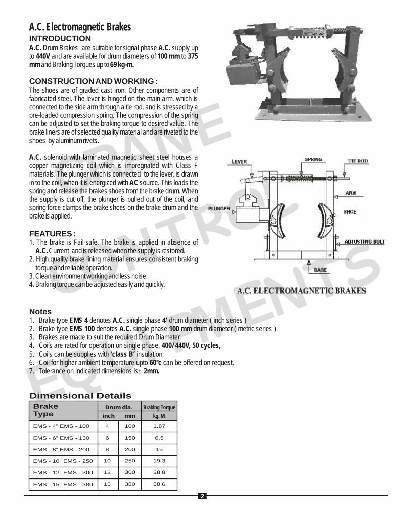
A.C. Electromagnetic BrakesINTRODUCTIONA.C. Drum Brakes are suitable for signal phase A.C. supply up to 440V and are available for drum diameters of 100 mm to 375 mm and Braking Torques up to 69 kg-m.
CONSTRUCTION AND WORKING :The shoes are of graded cast iron. Other components are of fabricated steel. The lever is hinged on the main arm. which is connected to the side arm through a tie rod, and is stressed by a pre-loaded compression spring. The compression of the spring can be adjusted to set the braking torque to desired value. The brake liners are of selected quality material and are riveted to the shoes by aluminum rivets.
A.C. solenoid with laminated magnetic sheet steel houses a copper magnetizing coil which is impregnated with Class F materials. The plunger which is connected to the lever, is drawn in to the coil, when it is energized with AC source. This loads the spring and release the brakes shoes from the brake drum. When the supply is cut off, the plunger is pulled out of the coil, and spring force clamps the brake shoes on the brake drum and the brake is applied.
FEATURES :1. The brake is Fail-safe. The brake is applied in absence of
A.C. Current and is released when the supply is restored.2. High quality brake lining material ensures consistent braking
torque and reliable operation.3. Clean environment working and less noise.4. Braking torque can be adjusted easily and quickly.
Notes1. Brake type EMS 4 denotes A.C. single phase 4’ drum diameter ( inch series )2. Brake type EMS 100 denotes A.C. single phase 100 mm drum diameter ( metric series )3. Brakes are made to suit the required Drum Diameter.4. Coils are rated for operation on single phase, 400/ 440V, 50 cycles,5. Coils can be supplies with ‘class B’ insulation.6. Coil for higher ambient temperature upto 60°c can be offered on request,7. Tolerance on indicated dimensions is± 2mm.
Dimensional DetailsBrake Type
EMS - 4” EMS - 100
EMS - 6” EMS - 150
EMS - 8” EMS - 200
EMS - 10” EMS - 250
EMS - 12” EMS - 300
EMS - 15” EMS - 380
Drum dia.
inch mm
Braking Torque
kg. M.
4
6
8
10
12
15
100
150
200
250
300
380
1.87
6.5
15
19.3
38.8
58.6
2
ADJUSTING BOLT

R NE C A
CONTROL
EU
E T
QIPM
NS
Electro-Hydraulic Thrusters (ST)ELECTRICAL SUPPLY :Unless otherwise specified, all thrusters are suitable for operation for 415 Volts,-phase, 50 Hz power supply. Thrusters for other voltages up to 600 VAC, 3-phase can be supplied against specific enquiries.
CONNECTIONS :The Thrusters operate equally well in both directions of rotation. Therefore, the three phase supply lines can be connected the Thrusters in any R-Y-B phase sequence. Provide adequate safety backups.
OIL REQUIREMENTS :Thrusters are supplied without oil to avoid spillage during transportation. They must be filled with sufficient quantity of oil before installation. For all models of thrusters, it is recommended to use Transformer Oil as specified in BS : 148.
INSTALLATION OF THRUSTERS :All Thrusters are suitable for vertical mounting only. After filling the thruster with required quantity of oil, install it by using the clevis and hinge pins provided. Insert the locking split pins.
Ensure that no excessive transverse forces are acting on the thrust rod. Wipe out the dust, paint or oil deposits from the operating section of the thrust rod pins by dry and clean cloth.
MAINTENANCE :The Thrusters is designed for long trouble free service. The motor windings are designed to meet contingencies, The bearings are adequately sized.
Routine maintenance schedule includes checking the oil levels and topping them if necessary. If oil contamination is detected, drain it out completely and refill with fresh oil. Check and correct
DIMENSIONS TYPE
RATEDTHRUST
KGS. (N)
ST 520 18 (180) 51 51
76 76
127 127
ST 535 34 (340)
ST 545 45 (450)
ST 870 68 (680)
ST 8110 114 (1140)
ST 13200 225 (2250)
ST 13300 295 (2950)
OUTPUTSTROKE
MM.
INPUTWATTS
90 349
444
508
660
150
180
200
250
420
580
A B C D E
159
171
216
254
19
22
25
32
25
29
32
38
F
13
14
16
19
G J K ML P Qwt.
(kg.)
OILCAPACITY
LITERSH
12.7 16 19 19
19.7 21 27 25
22.2 24 29 32
25.4 27 45 38
19
25
30
32 110 90 14
41 138 118 30
48 152 132 40
54 152 132 55
2.0
2.5
4.5
9.0
3
R NE C A
CONTROL
EU
E T
QIPM
NS
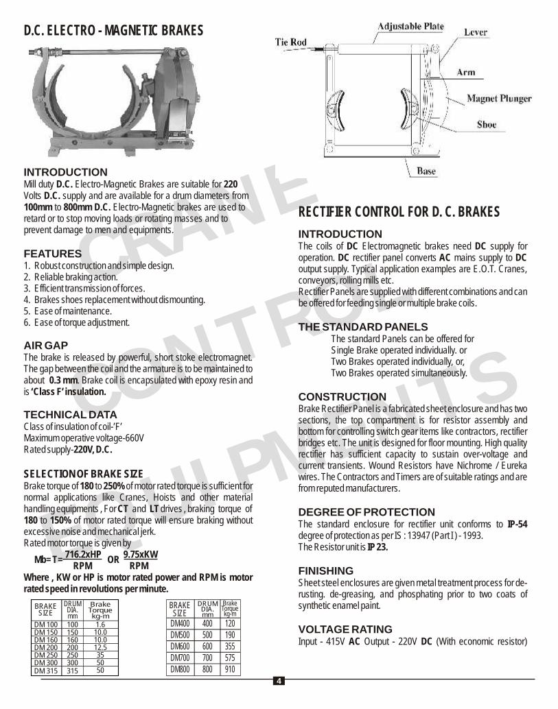
D.C. ELECTRO - MAGNETIC BRAKES
INTRODUCTIONMill duty D.C. Electro-Magnetic Brakes are suitable for 220 Volts D.C. supply and are available for a drum diameters from 100mm to 800mm D.C. Electro-Magnetic brakes are used to retard or to stop moving loads or rotating masses and to prevent damage to men and equipments.
FEATURES1. Robust construction and simple design.2. Reliable braking action.3. Efficient transmission of forces.4. Brakes shoes replacement without dismounting.5. Ease of maintenance.6. Ease of torque adjustment.
AIR GAPThe brake is released by powerful, short stoke electromagnet. The gap between the coil and the armature is to be maintained to about 0.3 mm. Brake coil is encapsulated with epoxy resin and is ‘Class F’ insulation. TECHNICAL DATAClass of insulation of coil-’F’Maximum operative voltage-660VRated supply-220V, D.C.
SELECTION OF BRAKE SIZEBrake torque of 180 to 250% of motor rated torque is sufficient for normal applications like Cranes, Hoists and other material handling equipments , For CT and LT drives , braking torque of180 to 150% of motor rated torque will ensure braking without excessive noise and mechanical jerk.Rated motor torque is given by 716.2xHP 9.75xKW
Mb= T = OR RPM RPM Where , KW or HP is motor rated power and RPM is motor rated speed in revolutions per minute.
BRAKESIZE
DM400DM500DM600DM700DM800
DRUMDIA.mm
400500600700800
BrakeTorquekg-m
120190355575910
RECTIFIER CONTROL FOR D. C. BRAKES
INTRODUCTIONThe coils of DC Electromagnetic brakes need DC supply for operation. DC rectifier panel converts AC mains supply to DC output supply. Typical application examples are E.O.T. Cranes, conveyors, rolling mills etc.Rectifier Panels are supplied with different combinations and can be offered for feeding single or multiple brake coils.
THE STANDARD PANELSThe standard Panels can be offered forSingle Brake operated individually. orTwo Brakes operated individually, or,Two Brakes operated simultaneously.
CONSTRUCTIONBrake Rectifier Panel is a fabricated sheet enclosure and has two sections, the top compartment is for resistor assembly and bottom for controlling switch gear items like contractors, rectifier bridges etc. The unit is designed for floor mounting. High quality rectifier has sufficient capacity to sustain over-voltage and current transients. Wound Resistors have Nichrome / Eureka wires. The Contractors and Timers are of suitable ratings and are from reputed manufacturers.
DEGREE OF PROTECTIONThe standard enclosure for rectifier unit conforms to IP-54 degree of protection as per IS : 13947 (Part I ) - 1993.The Resistor unit is IP 23.
FINISHINGSheet steel enclosures are given metal treatment process for de-rusting. de-greasing, and phosphating prior to two coats of synthetic enamel paint.
VOLTAGE RATINGInput - 415V AC Output - 220V DC (With economic resistor)
BRAKESIZE
DRUMDIA.mm
BrakeTorquekg-m
DM 100DM 150DM 160DM 200DM 250DM 300DM 315
100150160200250300315
1.610.010.012.5355050
4
N CRA
E
CONTROL
EU
EQ
IPMNTS
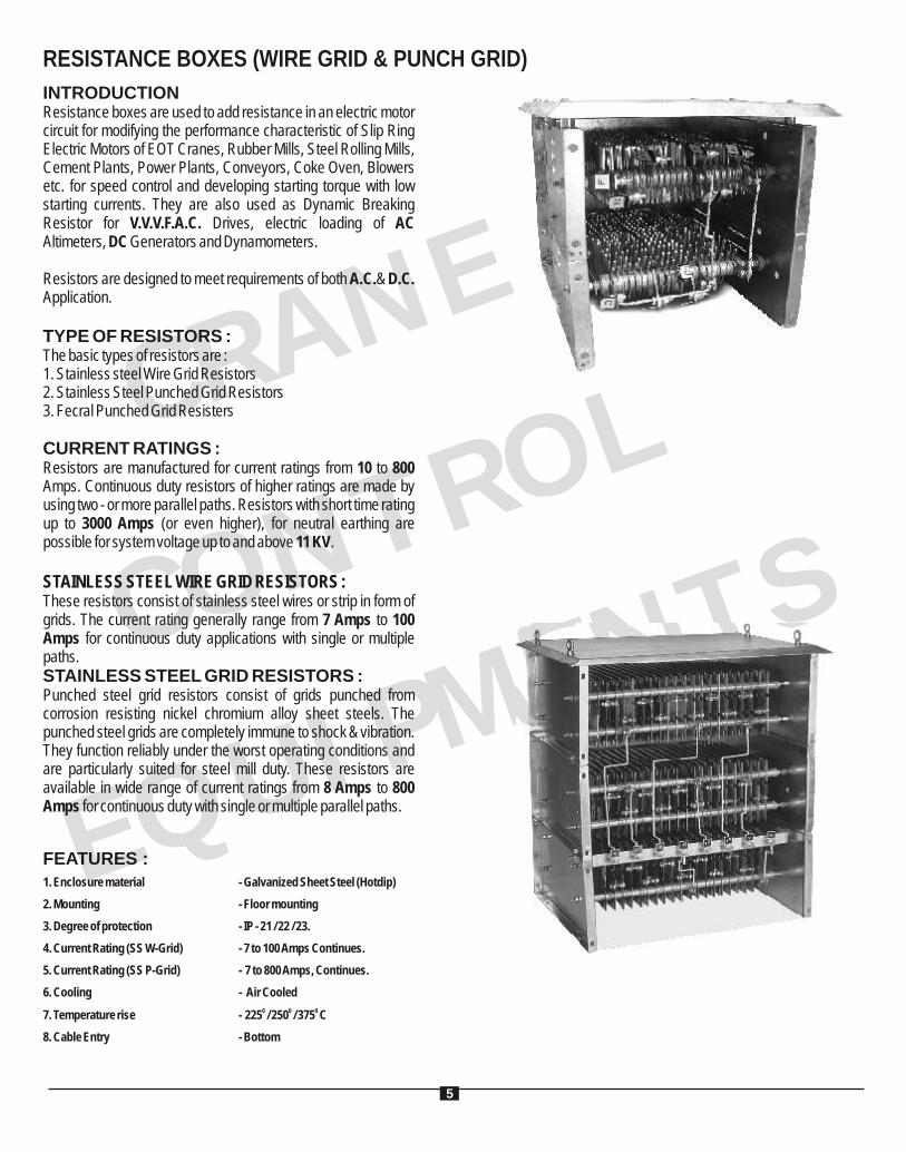
RESISTANCE BOXES (WIRE GRID & PUNCH GRID)
INTRODUCTIONResistance boxes are used to add resistance in an electric motor circuit for modifying the performance characteristic of Slip Ring Electric Motors of EOT Cranes, Rubber Mills, Steel Rolling Mills, Cement Plants, Power Plants, Conveyors, Coke Oven, Blowers etc. for speed control and developing starting torque with low starting currents. They are also used as Dynamic Breaking Resistor for V.V.V.F.A.C. Drives, electric loading of AC Altimeters, DC Generators and Dynamometers.
Resistors are designed to meet requirements of both A.C.& D.C. Application.
TYPE OF RESISTORS :The basic types of resistors are :1. Stainless steel Wire Grid Resistors2. Stainless Steel Punched Grid Resistors3. Fecral Punched Grid Resisters CURRENT RATINGS :Resistors are manufactured for current ratings from 10 to 800 Amps. Continuous duty resistors of higher ratings are made by using two - or more parallel paths. Resistors with short time rating up to 3000 Amps (or even higher), for neutral earthing are possible for system voltage up to and above 11 KV.
STAINLESS STEEL WIRE GRID RESISTORS :These resistors consist of stainless steel wires or strip in form of grids. The current rating generally range from 7 Amps to 100 Amps for continuous duty applications with single or multiple paths.STAINLESS STEEL GRID RESISTORS :Punched steel grid resistors consist of grids punched from corrosion resisting nickel chromium alloy sheet steels. The punched steel grids are completely immune to shock & vibration. They function reliably under the worst operating conditions and are particularly suited for steel mill duty. These resistors are available in wide range of current ratings from 8 Amps to 800 Amps for continuous duty with single or multiple parallel paths.
FEATURES :1. Enclosure material - Galvanized Sheet Steel (Hotdip)
2. Mounting - Floor mounting
3. Degree of protection - IP - 21 / 22 / 23.
4. Current Rating (SS W-Grid) - 7 to 100 Amps Continues.
5. Current Rating (SS P-Grid) - 7 to 800 Amps, Continues.
6. Cooling - Air Cooled
0 0 07. Temperature rise - 225 / 250 / 375 C
8. Cable Entry - Bottom
5
R N C A
E
CONTROL
EU
EQ
IPMNTS
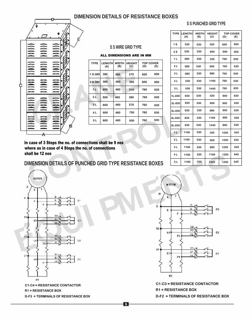
DIMENSION DETAILS OF RESISTANCE BOXES
S S WIRE GRID TYPE
S S PUNCHED GRID TYPE
DIMENSION DETAILS OF PUNCHED GRID TYPE RESISTANCE BOXES
6
CRANE
CONTROL
EQUIPM
E TSN
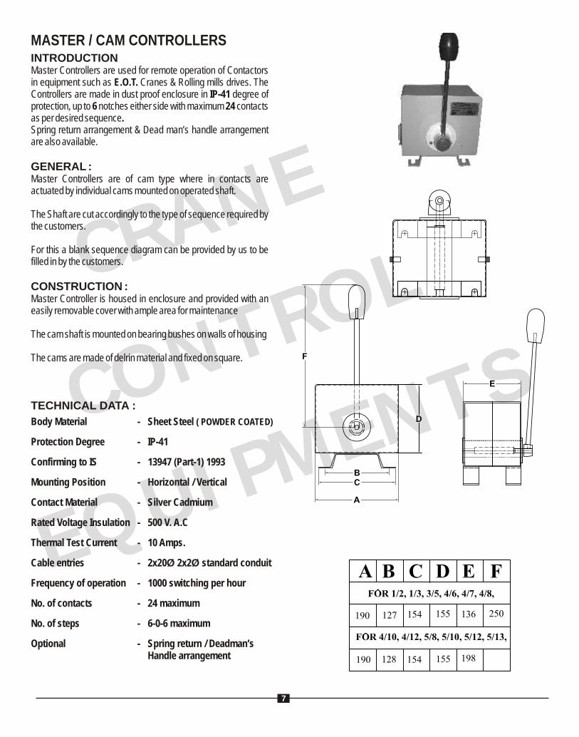
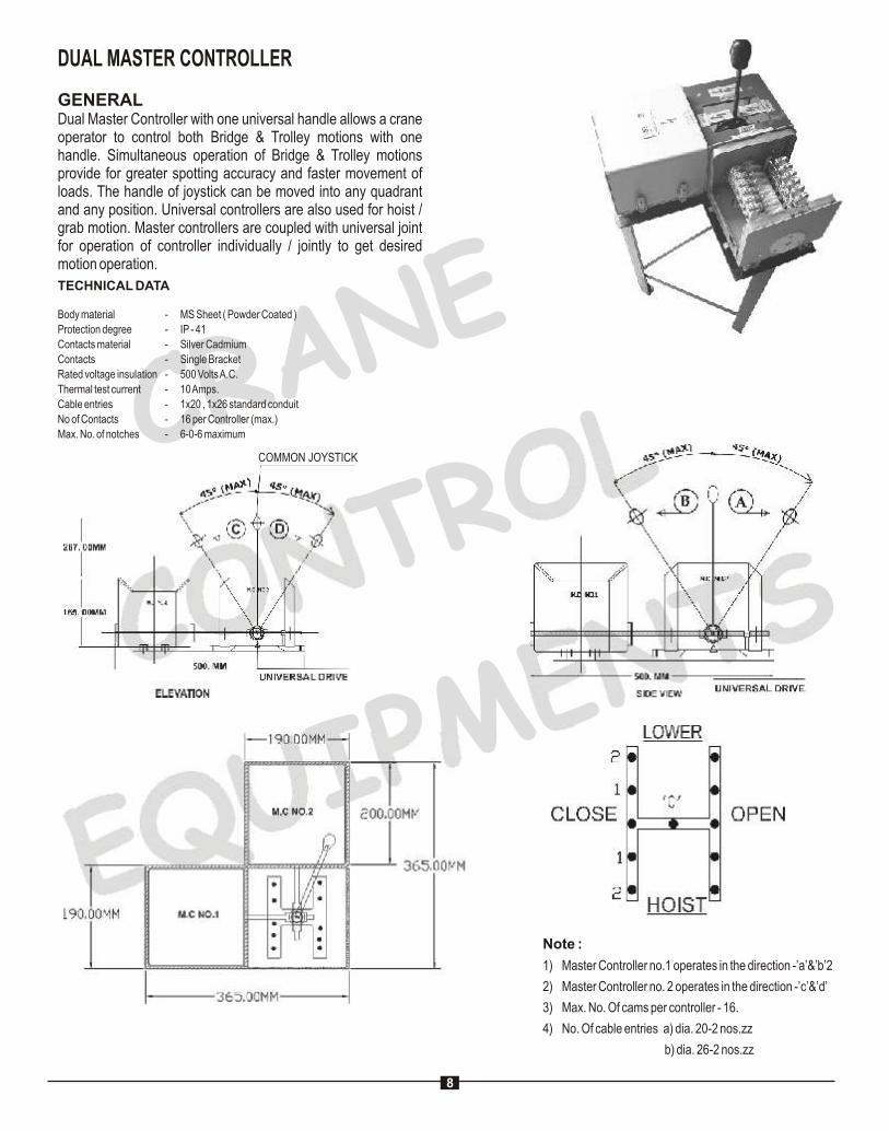
MASTER / CAM CONTROLLERSINTRODUCTIONMaster Controllers are used for remote operation of Contactors in equipment such as E.O.T. Cranes & Rolling mills drives. The Controllers are made in dust proof enclosure in IP-41 degree of protection, up to 6 notches either side with maximum 24 contacts as per desired sequence.Spring return arrangement & Dead man’s handle arrangement are also available.
GENERAL :Master Controllers are of cam type where in contacts are actuated by individual cams mounted on operated shaft.
The Shaft are cut accordingly to the type of sequence required by the customers.
For this a blank sequence diagram can be provided by us to be filled in by the customers.
CONSTRUCTION :Master Controller is housed in enclosure and provided with an easily removable cover with ample area for maintenance
The cam shaft is mounted on bearing bushes on walls of housing
The cams are made of delrin material and fixed on square.
Body Material - Sheet Steel ( POWDER COATED)
Protection Degree - IP-41
Confirming to IS - 13947 (Part-1) 1993
Mounting Position - Horizontal / Vertical
Contact Material - Silver Cadmium
Rated Voltage Insulation - 500 V. A.C
Thermal Test Current - 10 Amps.
Cable entries - 2x20Ø 2x2Ø standard conduit
Frequency of operation - 1000 switching per hour
No. of contacts - 24 maximum
No. of steps - 6-0-6 maximum
Optional - Spring return / Deadman’sHandle arrangement
TECHNICAL DATA :
7
RANE C
CONTROL
EU P E T
QI M
NS
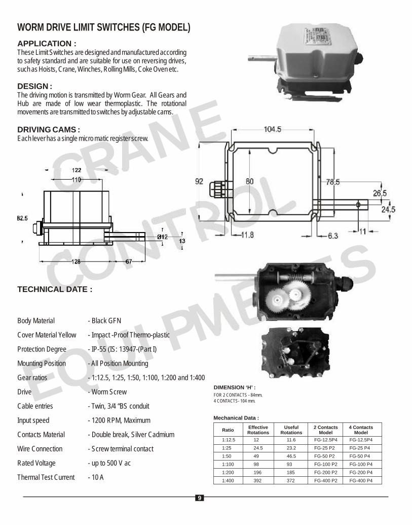
WORM DRIVE LIMIT SWITCHES (FG MODEL)
APPLICATION :These Limit Switches are designed and manufactured according to safety standard and are suitable for use on reversing drives, such as Hoists, Crane, Winches, Rolling Mills, Coke Oven etc.
DESIGN :The driving motion is transmitted by Worm Gear. All Gears and Hub are made of low wear thermoplastic. The rotational movements are transmitted to switches by adjustable cams.
DRIVING CAMS :Each lever has a single micro matic register screw.
Body Material - Black GFN
Cover Material Yellow - Impact -Proof Thermo-plastic
Protection Degree - IP-55 (IS: 13947-(Part I)
Mounting Position - All Position Mounting
Gear ratios - 1:12.5, 1:25, 1:50, 1:100, 1:200 and 1:400
Drive - Worm Screw
Cable entries - Twin, 3/4 “BS conduit
Input speed - 1200 RPM, Maximum
Contacts Material - Double break, Silver Cadmium
Wire Connection - Screw terminal contact
Rated Voltage - up to 500 V ac
Thermal Test Current - 10 A
TECHNICAL DATE :
DIMENSION ‘H’ :
RatioEffectiveRotations
1:12.5
1:25
1:50
1:100
1:200
1:400
12
24.5
49
98
196
392
UsefulRotations
4 ContactsModel
11.6
23.2
46.5
93
185
372
2 ContactsModel
FG-12.5P4
FG-25 P2
FG-50 P2
FG-100 P2
FG-200 P2
FG-400 P2
FG-12.5P4
FG-25 P4
FG-50 P4
FG-100 P4
FG-200 P4
FG-400 P4
Mechanical Data :
FOR 2 CONTACTS - 84mm.4 CONTACTS- 104 mm.
9

RANE C
CONTROL
EU P E T
QI M
NS
ROTARY GEARED LIMIT SWITCHES (MODEL GRLS)
INTRODUCTION :
Rotary Geared Limit Switch GRLS is used to trip supply when the moving loads reach the extreme end positions of working zone.
OPERATION :
A two (for more) Contact Elements are operated by respective rotating Cams, suitable adjusted on a Cam Shaft which rotates with fixed speed ratio of the drive motor shaft. The cams can be suitably positioned so that they trip motor supply and stop the motion at the required point of travel.
APPLICATION :
Rotary Geared limit Switches are suitable for use on reversing drives such as Hoists, Winches, Rolling Mills and various other mechanisms used in Steel Plants such as Coke Oven, Feeding
BODY MATERIAL
PROTECTION DEGREE
GEAR TATIO
DRIVE
CABLE ENTRIES
CONTACT MATERIAL
RATED VOLTAGE INSULATION
THERMAL TEST CURRENT
NO. OF CONTACT
CAM SETTING
MS Sheet ( Powder Coated )
IP-41 CONFIRMING TO IS-13947(PART)-1)1993
48 : 1 60 : 1 96:1
WORM DRIVE
2 X 3/4” CONDUIT
SILVER CADMIUM
500 V.A.C.
10 Amps. / 40 Amps.
2 NC OR 4 NC
ADJUSTABLE
RotationEffectiveRotations
UsefulRotation
2 ContactsModel
ContactsModel
48 :1 42 40 GRLS/48/2SH
GRLS/60/2SH
GRLS/96/2SH
60 :1 52 50
96 :1 84 80
GRLS/48/4SH
GRLS/60/4SH
GRLS/96/4SH
10
RANE C
CONTROL
EU P E T
QI M
NS
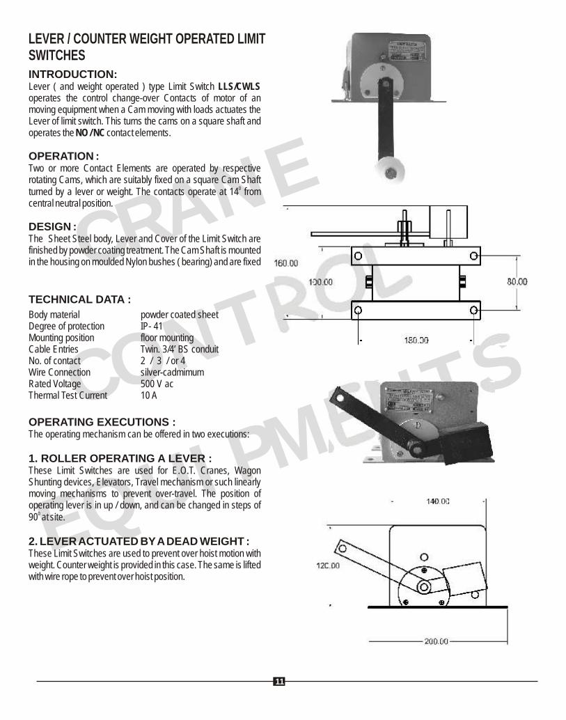
LEVER / COUNTER WEIGHT OPERATED LIMITSWITCHESINTRODUCTION:Lever ( and weight operated ) type Limit Switch LLS/CWLS operates the control change-over Contacts of motor of an moving equipment when a Cam moving with loads actuates the Lever of limit switch. This turns the cams on a square shaft and operates the NO / NC contact elements.
OPERATION :Two or more Contact Elements are operated by respective rotating Cams, which are suitably fixed on a square Cam Shaft
0turned by a lever or weight. The contacts operate at 14 from central neutral position.
DESIGN :The Sheet Steel body, Lever and Cover of the Limit Switch are finished by powder coating treatment. The Cam Shaft is mounted in the housing on moulded Nylon bushes ( bearing) and are fixed
OPERATING EXECUTIONS :The operating mechanism can be offered in two executions:
1. ROLLER OPERATING A LEVER :These Limit Switches are used for E.O.T. Cranes, Wagon Shunting devices, Elevators, Travel mechanism or such linearly moving mechanisms to prevent over-travel. The position of operating lever is in up / down, and can be changed in steps of
090 at site.
2. LEVER ACTUATED BY A DEAD WEIGHT :These Limit Switches are used to prevent over hoist motion with weight. Counter weight is provided in this case. The same is lifted with wire rope to prevent over hoist position.
TECHNICAL DATA :
Body material powder coated sheet Degree of protection IP- 41Mounting position floor mountingCable Entries Twin. 3/4’ BS conduitNo. of contact 2 / 3 / or 4Wire Connection silver-cadmimumRated Voltage 500 V acThermal Test Current 10 A
11
R N C A
E
CONTROL
EU
EQ
IPMNTS
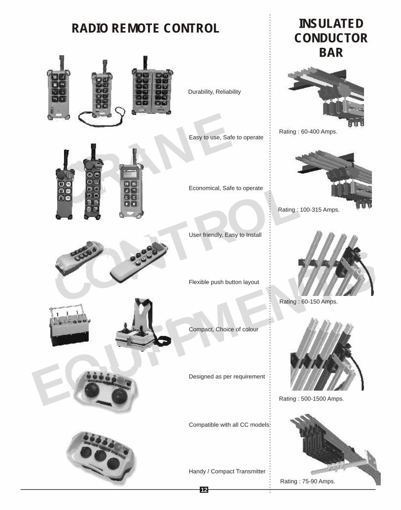
Handy / Compact Transmitter
Compatible with all CC models
User friendly, Easy to Install
Economical, Safe to operate
Easy to use, Safe to operate
Durability, Reliability
Flexible push button layout
Compact, Choice of colour
Designed as per requirement
RADIO REMOTE CONTROL
Rating : 60-400 Amps.
Rating : 100-315 Amps.
Rating : 60-150 Amps.
Rating : 500-1500 Amps.
Rating : 75-90 Amps.
INSULATED CONDUCTOR
BAR
12