cr800 & cr850 measurement and control systems brochure
TRANSCRIPT
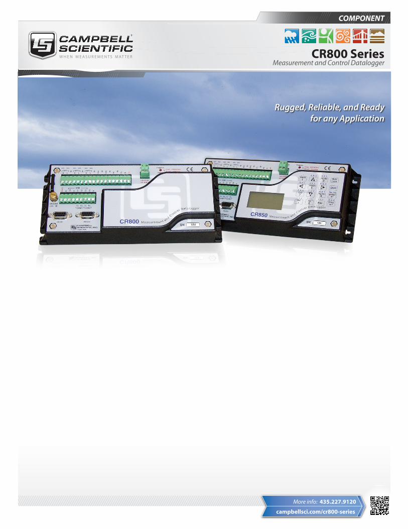
Rugged, Reliable, and Ready for any Application
COMPONENT
CR800 SeriesMeasurement and Control Datalogger
campbellsci.com/cr800-series
More info: 435.227.9120
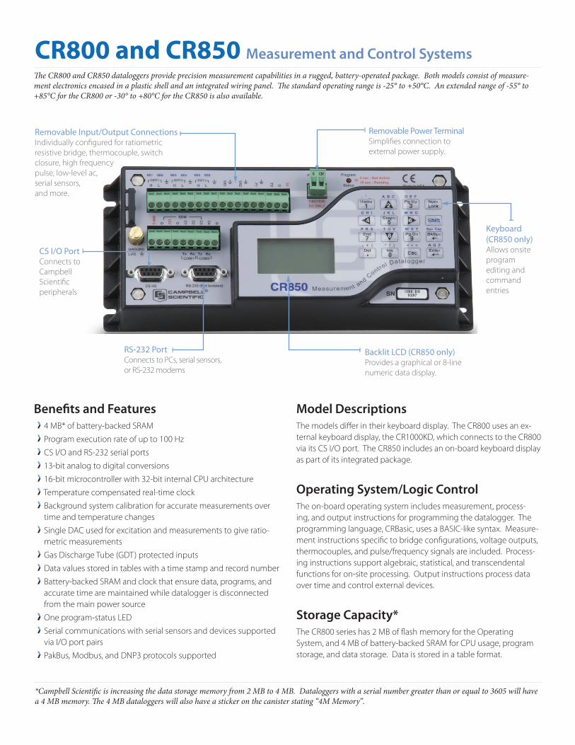
The CR800 and CR850 dataloggers provide precision measurement capabilities in a rugged, battery-operated package. Both models consist of measure-ment electronics encased in a plastic shell and an integrated wiring panel. The standard operating range is -25° to +50°C. An extended range of -55° to +85°C for the CR800 or -30° to +80°C for the CR850 is also available.
Benefits and Features4 MB* of battery-backed SRAM
Program execution rate of up to 100 Hz
CS I/O and RS-232 serial ports
13-bit analog to digital conversions
16-bit microcontroller with 32-bit internal CPU architecture
Temperature compensated real-time clock
Background system calibration for accurate measurements over time and temperature changes
Single DAC used for excitation and measurements to give ratio-metric measurements
Gas Discharge Tube (GDT) protected inputs
Data values stored in tables with a time stamp and record number
Battery-backed SRAM and clock that ensure data, programs, and accurate time are maintained while datalogger is disconnected from the main power source
One program-status LED
Serial communications with serial sensors and devices supported via I/O port pairs
PakBus, Modbus, and DNP3 protocols supported
Model DescriptionsThe models differ in their keyboard display. The CR800 uses an ex-ternal keyboard display, the CR1000KD, which connects to the CR800 via its CS I/O port. The CR850 includes an on-board keyboard display as part of its integrated package.
Operating System/Logic ControlThe on-board operating system includes measurement, process-ing, and output instructions for programming the datalogger. The programming language, CRBasic, uses a BASIC-like syntax. Measure-ment instructions specific to bridge configurations, voltage outputs, thermocouples, and pulse/frequency signals are included. Process-ing instructions support algebraic, statistical, and transcendental functions for on-site processing. Output instructions process data over time and control external devices.
Storage Capacity*The CR800 series has 2 MB of flash memory for the Operating System, and 4 MB of battery-backed SRAM for CPU usage, program storage, and data storage. Data is stored in a table format.
CR800 and CR850 Measurement and Control Systems
*Campbell Scientific is increasing the data storage memory from 2 MB to 4 MB. Dataloggers with a serial number greater than or equal to 3605 will have a 4 MB memory. The 4 MB dataloggers will also have a sticker on the canister stating “4M Memory”.
RS-232 PortConnects to PCs, serial sensors, or RS-232 modems
Keyboard (CR850 only)Allows onsite program editing and command entries
Backlit LCD (CR850 only)Provides a graphical or 8-line numeric data display.
Removable Input/Output Connections Individually configured for ratiometric resistive bridge, thermocouple, switch closure, high frequency pulse, low-level ac, serial sensors, and more.
Removable Power TerminalSimplifies connection to external power supply.
CS I/O Port Connects to Campbell Scientific peripherals
Input Output TerminalsAnalog Inputs Three differential (6 single-ended) channels measure voltage levels. Resolution on the most sensitive range is 0.67 µV.
Pulse Counters The CR800 and CR850 have two pulse channels that can count pulses from high level (5 V square wave), switch closure, or low level AC signals.
Switched Voltage ExcitationsTwo outputs provide precision excitation voltages for resistive bridge measurements.
Digital I/O Ports The CR800-series dataloggers include four ports for frequency mea-surements, digital control, and triggering. Three of these ports can also be used to measure SDM devices. The I/O ports can be paired as transmit and receive. Each pair has 0 to 5 V UART hardware that allows serial communications with serial sensors and devices. An RS-232-to-logic level converter may be required in some cases.
CS I/O PortAC-powered PCs and many communication peripherals connect with the datalogger via this port. Connection to an AC-powered PC requires either an SC32B or SC-USB interface. These interfaces isolate the PC’s electrical system from the datalogger, thereby protecting against ground loops, normal static discharge, and noise.
RS-232 Port This non-isolated port is for connecting a battery-powered laptop, serial sensor, or RS-232 modem. Because of ground loop potential on some measurements (e.g., low level single-ended), AC-powered PCs should use the CS I/O port instead of the RS-232 port (see above).
Switched 12 VoltThis terminal provides unregulated 12 Vdc that can be switched on and off under program control.
Transient ProtectionGas Discharge Tube (GDT) protects the inputs from electrical tran-sients. The CR800 series is CE compliant under the European Union’s EMC Directive, meeting ESD, EMC, Fast Transient standards.
Communication Protocols The CR800 series supports the PakBus, Modbus, DNP3,TCP/IP, FTP, and SMTP communication protocols. With the PakBus protocol, networks have the distributed routing intelligence to continually evaluate links. Continually evaluating links optimizes delivery times and, in the case of delivery failure, allows automatic switch over to a configured backup route.
The Modbus RTU protocol supports both floating point and long formats. The datalogger can act as a slave and/or master.
The DNP3 protocol supports only long data formats. The dataloggers are level 2 slave compliant, with some of the operations found in a level 3 implementation.
The TCP/IP, FTP, and SMTP protocols provide TCP/IP functionality when the datalogger is used in conjunction with an NL201 or NL240.
Enclosure/Stack BracketA CR800 or CR850 housed in a weather-resistant enclosure can collect data under extremely harsh conditions. The 31551 and 31143 stack brackets allow a peripheral to be placed under the mounting bracket, thus conserving space. The 31143 is hinged, allowing easy access to the lower component during wiring or during maintenance.
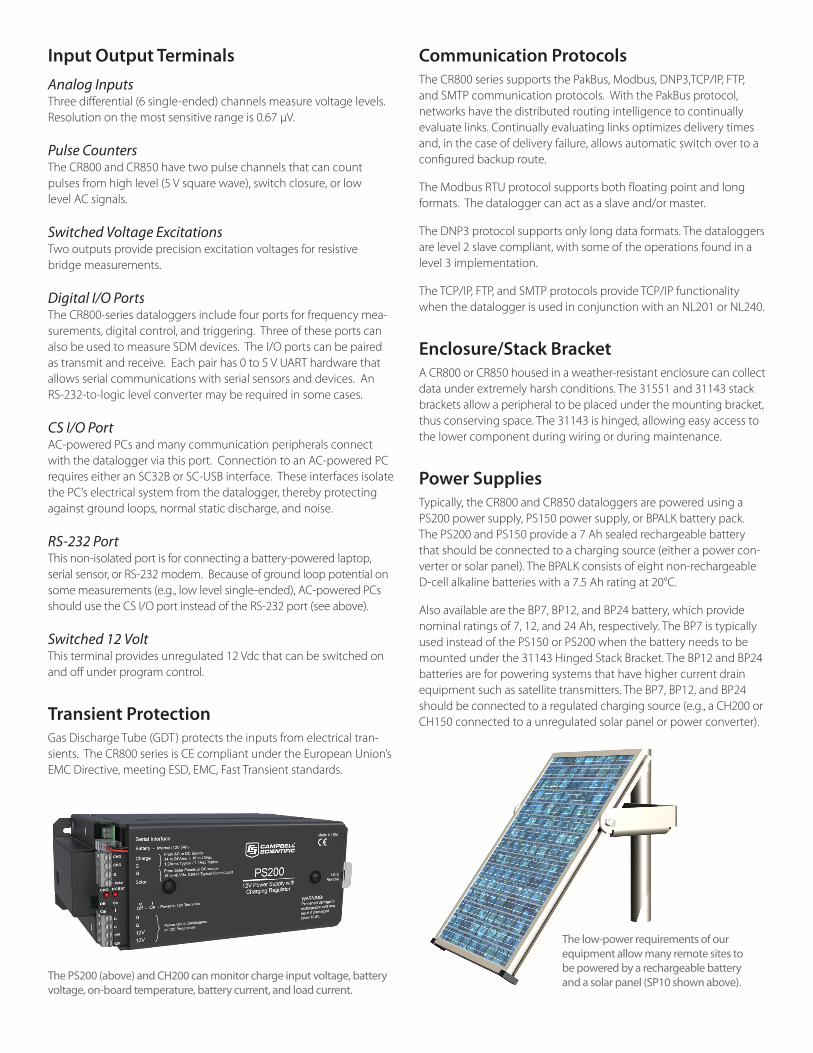
Power SuppliesTypically, the CR800 and CR850 dataloggers are powered using a PS200 power supply, PS150 power supply, or BPALK battery pack. The PS200 and PS150 provide a 7 Ah sealed rechargeable battery that should be connected to a charging source (either a power con-verter or solar panel). The BPALK consists of eight non-rechargeable D-cell alkaline batteries with a 7.5 Ah rating at 20°C.
Also available are the BP7, BP12, and BP24 battery, which provide nominal ratings of 7, 12, and 24 Ah, respectively. The BP7 is typically used instead of the PS150 or PS200 when the battery needs to be mounted under the 31143 Hinged Stack Bracket. The BP12 and BP24 batteries are for powering systems that have higher current drain equipment such as satellite transmitters. The BP7, BP12, and BP24 should be connected to a regulated charging source (e.g., a CH200 or CH150 connected to a unregulated solar panel or power converter).
The PS200 (above) and CH200 can monitor charge input voltage, battery voltage, on-board temperature, battery current, and load current.
The low-power requirements of our equipment allow many remote sites to be powered by a rechargeable battery and a solar panel (SP10 shown above).
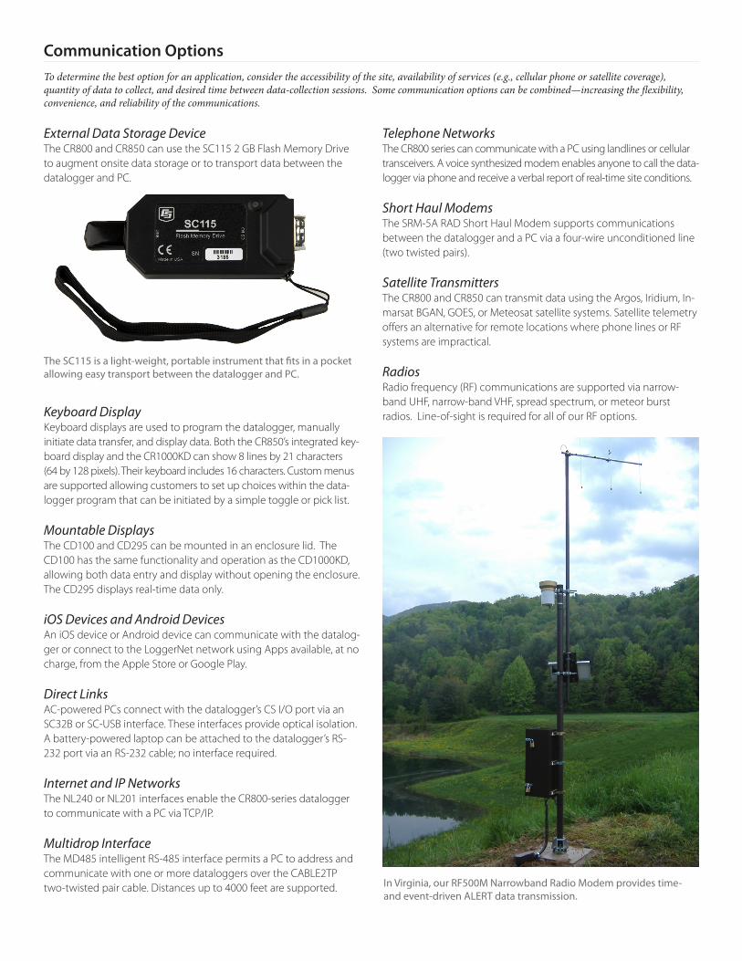
External Data Storage Device The CR800 and CR850 can use the SC115 2 GB Flash Memory Drive to augment onsite data storage or to transport data between the datalogger and PC.
Keyboard Display Keyboard displays are used to program the datalogger, manually initiate data transfer, and display data. Both the CR850’s integrated key- board display and the CR1000KD can show 8 lines by 21 characters (64 by 128 pixels). Their keyboard includes 16 characters. Custom menus are supported allowing customers to set up choices within the data-logger program that can be initiated by a simple toggle or pick list.
Mountable DisplaysThe CD100 and CD295 can be mounted in an enclosure lid. The CD100 has the same functionality and operation as the CD1000KD, allowing both data entry and display without opening the enclosure. The CD295 displays real-time data only.
iOS Devices and Android DevicesAn iOS device or Android device can communicate with the datalog-ger or connect to the LoggerNet network using Apps available, at no charge, from the Apple Store or Google Play.
Direct LinksAC-powered PCs connect with the datalogger’s CS I/O port via an SC32B or SC-USB interface. These interfaces provide optical isolation. A battery-powered laptop can be attached to the datalogger’s RS-232 port via an RS-232 cable; no interface required.
Internet and IP Networks The NL240 or NL201 interfaces enable the CR800-series datalogger to communicate with a PC via TCP/IP.
Multidrop InterfaceThe MD485 intelligent RS-485 interface permits a PC to address and communicate with one or more dataloggers over the CABLE2TP two-twisted pair cable. Distances up to 4000 feet are supported.
Telephone NetworksThe CR800 series can communicate with a PC using landlines or cellular transceivers. A voice synthesized modem enables anyone to call the data-logger via phone and receive a verbal report of real-time site conditions.
Short Haul Modems The SRM-5A RAD Short Haul Modem supports communications between the datalogger and a PC via a four-wire unconditioned line (two twisted pairs).
Satellite Transmitters The CR800 and CR850 can transmit data using the Argos, Iridium, In-marsat BGAN, GOES, or Meteosat satellite systems. Satellite telemetry offers an alternative for remote locations where phone lines or RF systems are impractical.
RadiosRadio frequency (RF) communications are supported via narrow-band UHF, narrow-band VHF, spread spectrum, or meteor burst radios. Line-of-sight is required for all of our RF options.
The SC115 is a light-weight, portable instrument that fits in a pocket allowing easy transport between the datalogger and PC.
In Virginia, our RF500M Narrowband Radio Modem provides time-and event-driven ALERT data transmission.
Communication OptionsTo determine the best option for an application, consider the accessibility of the site, availability of services (e.g., cellular phone or satellite coverage), quantity of data to collect, and desired time between data-collection sessions. Some communication options can be combined—increasing the flexibility, convenience, and reliability of the communications.
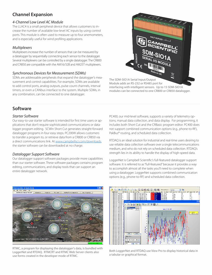
The SDM-SIO1A Serial Input/Output Module adds an RS-232 or RS485 port for interfacing with intelligent sensors. Up to 15 SDM-SIO1A modules can be connected to one CR800 or CR850 datalogger.
Channel Expansion4-Channel Low Level AC ModuleThe LLAC4 is a small peripheral device that allows customers to in-crease the number of available low-level AC inputs by using control ports. This module is often used to measure up to four anemometers, and is especially useful for wind profiling applications.
MultiplexersMultiplexers increase the number of sensors that can be measured by a datalogger by sequentially connecting each sensor to the datalogger. Several multiplexers can be controlled by a single datalogger. The CR800 and CR850 are compatible with the AM16/32B and AM25T multiplexers.
Synchronous Devices for Measurement (SDMs)SDMs are addressable peripherals that expand the datalogger’s mea-surement and control capabilities. For example, SDMs are available to add control ports, analog outputs, pulse count channels, interval timers, or even a CANbus interface to the system. Multiple SDMs, in any combination, can be connected to one datalogger.
RTMC, a program for displaying the datalogger’s data, is bundled with LoggerNet and RTDAQ. RTMCRT and RTMC Web Server clients also use forms created in the developer mode of RTMC.
Both LoggerNet and RTDAQ use View Pro to display historical data in a tabular or graphical format.
SoftwareStarter SoftwareOur easy-to-use starter software is intended for first time users or ap-plications that don’t require sophisticated communications or data-logger program editing. SCWin Short Cut generates straight-forward datalogger programs in four easy steps. PC200W allows customers to transfer a program to, or retrieve data from a CR800 or CR850 via a direct communications link. At www.campbellsci.com/downloads, the starter software can be downloaded at no charge.
Datalogger Support Software Our datalogger support software packages provide more capabilities than our starter software. These software packages contains program editing, communications, and display tools that can support an entire datalogger network.
PC400, our mid-level software, supports a variety of telemetry op-tions, manual data collection, and data display. For programming, it includes both Short Cut and the CRBasic program editor. PC400 does not support combined communication options (e.g., phone-to-RF), PakBus® routing, and scheduled data collection.
RTDAQ is an ideal solution for industrial and real-time users desiring to use reliable data collection software over a single telecommunications medium, and who do not rely on scheduled data collection. RTDAQ’s strength lies in its ability to handle the display of high-speed data.
LoggerNet is Campbell Scientific’s full-featured datalogger support software. It is referred to as “full-featured” because it provides a way to accomplish almost all the tasks you’ll need to complete when using a datalogger. LoggerNet supports combined communication options (e.g., phone-to-RF) and scheduled data collection.
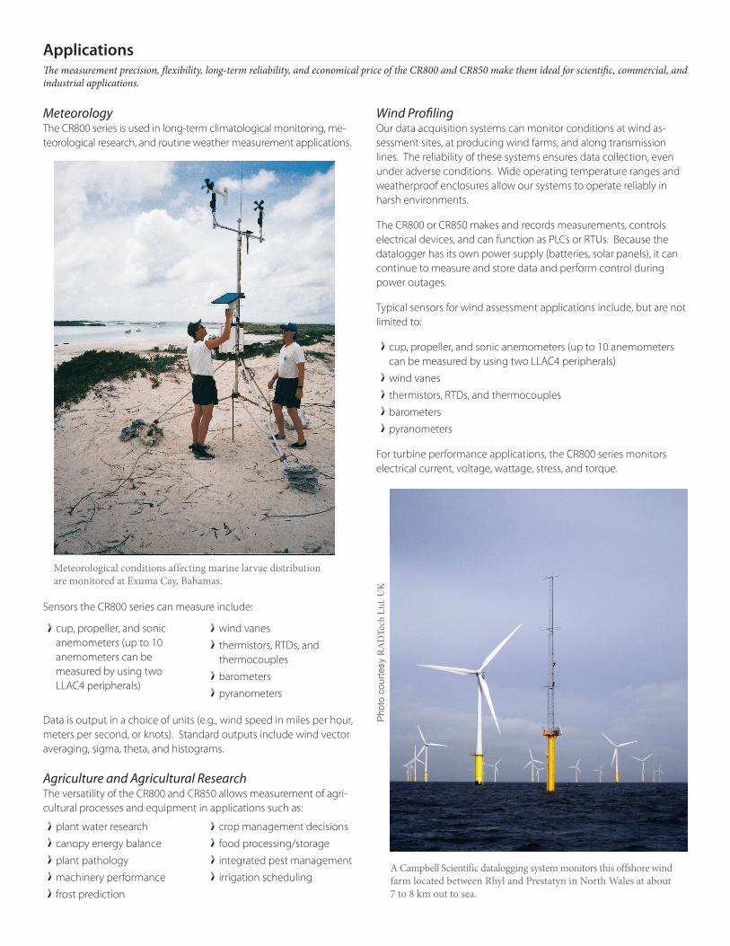
MeteorologyThe CR800 series is used in long-term climatological monitoring, me-teorological research, and routine weather measurement applications.
Sensors the CR800 series can measure include:
Data is output in a choice of units (e.g., wind speed in miles per hour, meters per second, or knots). Standard outputs include wind vector averaging, sigma, theta, and histograms.
Agriculture and Agricultural ResearchThe versatility of the CR800 and CR850 allows measurement of agri-cultural processes and equipment in applications such as:
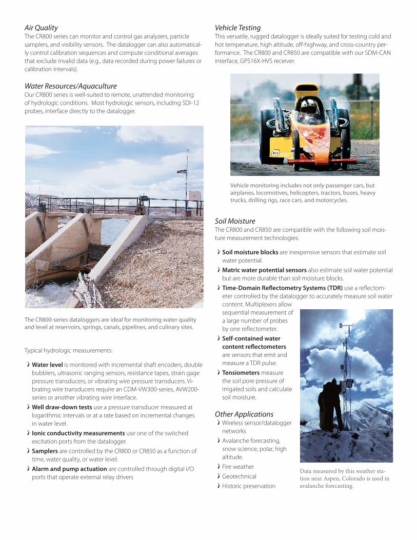
Wind ProfilingOur data acquisition systems can monitor conditions at wind as-sessment sites, at producing wind farms, and along transmission lines. The reliability of these systems ensures data collection, even under adverse conditions. Wide operating temperature ranges and weatherproof enclosures allow our systems to operate reliably in harsh environments.
The CR800 or CR850 makes and records measurements, controls electrical devices, and can function as PLCs or RTUs. Because the datalogger has its own power supply (batteries, solar panels), it can continue to measure and store data and perform control during power outages.
Typical sensors for wind assessment applications include, but are not limited to:
cup, propeller, and sonic anemometers (up to 10 anemometers can be measured by using two LLAC4 peripherals)
wind vanes
thermistors, RTDs, and thermocouples
barometers
pyranometers
For turbine performance applications, the CR800 series monitors electrical current, voltage, wattage, stress, and torque.
plant water research
canopy energy balance
plant pathology
machinery performance
frost prediction
crop management decisions
food processing/storage
integrated pest management
irrigation scheduling
Meteorological conditions affecting marine larvae distribution are monitored at Exuma Cay, Bahamas.
Phot
o co
urte
sy R
AD
Tech
Ltd
. UK
A Campbell Scientific datalogging system monitors this offshore wind farm located between Rhyl and Prestatyn in North Wales at about 7 to 8 km out to sea.
ApplicationsThe measurement precision, flexibility, long-term reliability, and economical price of the CR800 and CR850 make them ideal for scientific, commercial, and industrial applications.
cup, propeller, and sonic anemometers (up to 10 anemometers can be measured by using two LLAC4 peripherals)
wind vanes
thermistors, RTDs, and thermocouples
barometers
pyranometers
Air QualityThe CR800 series can monitor and control gas analyzers, particle samplers, and visibility sensors. The datalogger can also automatical-ly control calibration sequences and compute conditional averages that exclude invalid data (e.g., data recorded during power failures or calibration intervals).
Water Resources/AquacultureOur CR800 series is well-suited to remote, unattended monitoring of hydrologic conditions. Most hydrologic sensors, including SDI-12 probes, interface directly to the datalogger.
Typical hydrologic measurements:
Water level is monitored with incremental shaft encoders, double bubblers, ultrasonic ranging sensors, resistance tapes, strain gage pressure transducers, or vibrating wire pressure transducers. Vi-brating wire transducers require an CDM-VW300-series, AVW200-series or another vibrating wire interface.
Well draw-down tests use a pressure transducer measured at logarithmic intervals or at a rate based on incremental changes in water level.
Ionic conductivity measurements use one of the switched excitation ports from the datalogger.
Samplers are controlled by the CR800 or CR850 as a function of time, water quality, or water level.
Alarm and pump actuation are controlled through digital I/O ports that operate external relay drivers
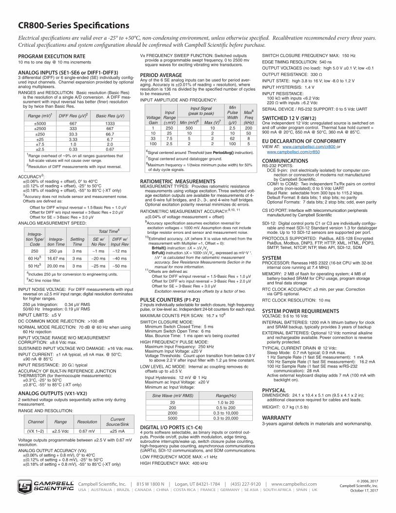
Vehicle TestingThis versatile, rugged datalogger is ideally suited for testing cold and hot temperature, high altitude, off-highway, and cross-country per-formance. The CR800 and CR850 are compatible with our SDM-CAN interface, GPS16X-HVS receiver.
Soil MoistureThe CR800 and CR850 are compatible with the following soil mois-ture measurement technologies:
Soil moisture blocks are inexpensive sensors that estimate soil water potential.
Matric water potential sensors also estimate soil water potential but are more durable than soil moisture blocks.
Time-Domain Reflectometry Systems (TDR) use a reflectom-eter controlled by the datalogger to accurately measure soil water content. Multiplexers allow sequential measurement of a large number of probes by one reflectometer.
Self-contained water content reflectometers are sensors that emit and measure a TDR pulse.
Tensiometers measure the soil pore pressure of irrigated soils and calculate soil moisture.
Other ApplicationsWireless sensor/datalogger networks
Avalanche forecasting, snow science, polar, high altitude.
Fire weather
Geotechnical
Historic preservation
The CR800-series dataloggers are ideal for monitoring water quality and level at reservoirs, springs, canals, pipelines, and culinary sites.
Vehicle monitoring includes not only passenger cars, but airplanes, locomotives, helicopters, tractors, buses, heavy trucks, drilling rigs, race cars, and motorcycles.
Data measured by this weather sta-tion near Aspen, Colorado is used in avalanche forecasting.
Campbell Scientic, Inc. | 815 W 1800 N | Logan, UT 84321-1784 | (435) 227-9120 | www.campbellsci.comUSA | AUSTRALIA | BRAZIL | CANADA | CHINA | COSTA RICA | FRANCE | GERMANY | SE ASIA | SOUTH AFRICA | SPAIN | UK
© 2006, 2017Campbell Scientific, Inc.
October 17, 2017
CR800-Series Specifications
PROGRAM EXECUTION RATE 10 ms to one day @ 10 ms increments
ANALOG INPUTS (SE1-SE6 or DIFF1-DIFF3) 3 differential (DIFF) or 6 single-ended (SE) individually config-ured input channels. Channel expansion provided by optional analog multiplexers.RANGES and RESOLUTION: Basic resolution (Basic Res) is the resolution of a single A/D conversion. A DIFF mea- surement with input reversal has better (finer) resolution by by twice than Basic Res.
Range (mV)1 DIFF Res (µV)2 Basic Res (µV)
±5000 667 1333±2500 333 667±250 33.3 66.7±25 3.33 6.7±7.5 1.0 2.0±2.5 0.33 0.67
1Range overhead of ~9% on all ranges guarantees that full-scale values will not cause over range. 2Resolution of DIFF measurements with input reversal.
ACCURACY3: ±(0.06% of reading + offset), 0° to 40°C ±(0.12% of reading + offset), -25° to 50°C ±(0.18% of reading + offset), -55° to 85°C (-XT only) 3Accuracy does not include sensor and measurement noise. Offsets are defined as:
Offset for DIFF w/input reversal = 1.5·Basic Res + 1.0 µV Offset for DIFF w/o input reversal = 3·Basic Res + 2.0 µV Offset for SE = 3·Basic Res + 3.0 µV
ANALOG MEASUREMENT SPEED:
Integra- tion Type/
CodeIntegra-
tion TimeSettling
Time
Total Time4
SE w/ No Rev
DIFF w/ Input Rev
250 250 µs 3 ms ~1 ms ~12 ms
60 Hz5 16.67 ms 3 ms ~20 ms ~40 ms
50 Hz5 20.00 ms 3 ms ~25 ms ~50 ms
4Includes 250 µs for conversion to engineering units.5AC line noise filter.
INPUT NOISE VOLTAGE: For DIFF measurements with input reversal on ±2.5 mV input range; digital resolution dominates for higher ranges. 250 µs Integration: 0.34 µV RMS 50/60 Hz Integration: 0.19 µV RMSINPUT LIMITS: ±5 VDC COMMON MODE REJECTION: >100 dBNORMAL MODE REJECTION: 70 dB @ 60 Hz when using 60 Hz rejectionINPUT VOLTAGE RANGE W/O MEASUREMENT CORRUPTION: ±8.6 Vdc max.SUSTAINED INPUT VOLTAGE W/O DAMAGE: ±16 Vdc max.INPUT CURRENT: ±1 nA typical, ±6 nA max. @ 50°C; ±90 nA @ 85°CINPUT RESISTANCE: 20 GΩ typicalACCURACY OF BUILT-IN REFERENCE JUNCTION THERMISTOR (for thermocouple measurements): ±0.3°C, -25° to 50°C ±0.8°C, -55° to 85°C (-XT only)
ANALOG OUTPUTS (VX1-VX2)2 switched voltage outputs sequentially active only during measurement.
RANGE AND RESOLUTION:
Channel Range ResolutionCurrent
Source/Sink
(VX 1–2) ±2.5 Vdc 0.67 mV ±25 mA
Voltage outputs programmable between ±2.5 V with 0.67 mV resolution.ANALOG OUTPUT ACCURACY (VX): ±(0.06% of setting + 0.8 mV), 0° to 40°C ±(0.12% of setting + 0.8 mV), -25° to 50°C ±(0.18% of setting + 0.8 mV), -55° to 85°C (-XT only)
Vx FREQUENCY SWEEP FUNCTION: Switched outputs provide a programmable swept frequency, 0 to 2500 mv square waves for exciting vibrating wire transducers.
PERIOD AVERAGE Any of the 6 SE analog inputs can be used for period aver-aging. Accuracy is ±(0.01% of reading + resolution), where resolution is 136 ns divided by the specified number of cycles to be measured.
INPUT AMPLITUDE AND FREQUENCY:
Voltage Gain
Input Range (±mV)
Input Signal (peak to peak)
Min Pulse Width (µV)
Max8 Freq (kHz) Min (mV)6 Max (V)7
1 250 500 10 2.5 20010 25 10 2 10 5033 7.5 5 2 62 8
100 2.5 2 2 100 5
6Signal centered around Threshold (see PeriodAvg() instruction).7Signal centered around datalogger ground. 8Maximum frequency = 1/(twice minimum pulse width) for 50% of duty cycle signals.
RATIOMETRIC MEASUREMENTS MEASUREMENT TYPES: Provides ratiometric resistance measurements using voltage excitation. Three switched volt- age excitation outputs are available for measurements of 4- and 6-wire full bridges, and 2-, 3-, and 4-wire half bridges. Optional excitation polarity reversal minimizes dc errors.
RATIOMETRIC MEASUREMENT ACCURACY:9,10, 11 ±(0.04% of voltage measurement + offset) 9Accuracy specification assumes excitation reversal for excitation voltages < 1000 mV. Assumption does not include bridge resistor errors and sensor and measurement noise.
10Estimated accuracy, ∆X (where X is value returned from the measurement with Multiplier =1, Offset = 0): BrHalf() instruction: ∆X = ∆V1/VX BrFull() instruction ∆X = 1000∆V1/VX, expressed as mVV−1. ∆V−1 is calculated from the ratiometric measurement accuracy. See Resistance Measurements Section in the manual for more information. 11Offsets are defined as: Offset for DIFF w/input reversal = 1.5Basic Res + 1.0 µV Offset for DIFF w/o input reversal = 3Basic Res + 2.0 µV Offset for SE = 3Basic Res + 3.0 µV Excitation reversal reduces offsets by a factor of two.
PULSE COUNTERS (P1-P2) 2 inputs individually selectable for switch closure, high frequency pulse, or low-level ac. Independent 24-bit counters for each input.
MAXIMUM COUNTS PER SCAN: 16.7 x 10⁶ SWITCH CLOSURE MODE: Minimum Switch Closed Time: 5 ms Minimum Switch Open Time: 6 ms Max. Bounce Time: 1 ms open w/o being counted
HIGH FREQUENCY PULSE MODE: Maximum Input Frequency: 250 kHz Maximum Input Voltage: ±20 V Voltage Thresholds: Count upon transition from below 0.9 V to above 2.2 V after input filter with 1.2 µs time constant.
LOW LEVEL AC MODE: Internal ac coupling removes dc offsets up to ±0.5 V.
Input Hysteresis: 12 mV @ 1 Hz Maximum ac Input Voltage: ±20 V Minimum ac Input Voltage:
Sine Wave (mV RMS) Range(Hz)
20 1.0 to 20200 0.5 to 2002000 0.3 to 10,0005000 0.3 to 20,000
DIGITAL I/O PORTS (C1-C4) 4 ports software selectable, as binary inputs or control out-puts. Provide on/off, pulse width modulation, edge timing, subroutine interrupts/wake up, switch closure pulse counting, high-frequency pulse counting, asynchronous communications (UARTs), SDI-12 communications, and SDM communications.
LOW FREQUENCY MODE MAX: <1 kHz
HIGH FREQUENCY MAX: 400 kHz
SWITCH CLOSURE FREQUENCY MAX: 150 Hz
EDGE TIMING RESOLUTION: 540 nsOUTPUT VOLTAGES (no load): high 5.0 V ±0.1 V; low <0.1
OUTPUT RESISTANCE: 330 Ω
INPUT STATE: high 3.8 to 16 V; low -8.0 to 1.2 V
INPUT HYSTERISIS: 1.4 V
INPUT RESISTANCE: 100 kΩ with inputs <6.2 Vdc 220 Ω with inputs ≥6.2 Vdc
SERIAL DEVICE / RS-232 SUPPORT: 0 to 5 Vdc UART
SWITCHED 12 V (SW12) One independent 12 Vdc unregulated source is switched on and off under program control. Thermal fuse hold current = 900 mA @ 20°C, 650 mA @ 50°C, 360 mA @ 85°C.
EU DECLARATION OF CONFORMITY VIEW AT: www.campbellsci.com/cr800 or www.campbellsci.com/cr850
COMMUNICATIONS RS-232 PORTS: DCE 9-pin: (not electrically isolated) for computer con- nection or connection of modems not manufactured by Campbell Scientific. COM1 to COM2: Two independent Tx/Rx pairs on control ports (non-isolated); 0 to 5 Vdc UART Baud Rate: selectable from 300 bps to 115.2 kbps. Default Format: 8 data bits; 1 stop bits; no parity Optional Formats: 7 data bits; 2 stop bits; odd, even parity
CS I/O PORT: Interface with telecommunication peripherals manufactured by Campbell Scientific
SDI-12: Digital control ports C1 or C3 are individually configu- rable and meet SDI-12 Standard version 1.3 for datalogger mode. Up to 10 SDI-12 sensors are supported per port.PROTOCOLS SUPPORTED: PakBus, AES-128 Encrypted PakBus, Modbus, DNP3, FTP, HTTP, XML, HTML, POP3, SMTP, Telnet, NTCIP, NTP, Web API, SDI-12, SDM
SYSTEM PROCESSOR: Renesas H8S 2322 (16-bit CPU with 32-bit internal core running at 7.4 MHz)
MEMORY: 2 MB of flash for operating system; 4 MB of battery-backed SRAM for CPU usage, program storage and final data storage
RTC CLOCK ACCURACY: ±3 min. per year. Correction via GPS optional.
RTC CLOCK RESOLUTION: 10 ms
SYSTEM POWER REQUIREMENTS VOLTAGE: 9.6 to 16 Vdc
INTERNAL BATTERIES: 1200 mA h lithium battery for clock and SRAM backup, typically provides 3 years of backupEXTERNAL BATTERIES: Optional 12 Vdc nominal alkaline and rechargeable available. Power connection is reverse polarity protected.TYPICAL CURRENT DRAIN @ 12 Vdc: Sleep Mode: 0.7 mA typical; 0.9 mA max. 1 Hz Sample Rate (1 fast SE measurement): 1 mA 100 Hz Sample Rate (1 fast SE measurement): 16.2 mA 100 Hz Sample Rate (1 fast SE meas w/RS-232 communication): 28 mA Active external keyboard display adds 7 mA (100 mA with backlight on).
PHYSICAL DIMENSIONS: 24.1 x 10.4 x 5.1 cm (9.5 x 4.1 x 2 in); additional clearance required for cables and leads.
WEIGHT: 0.7 kg (1.5 lb)
WARRANTY 3-years against defects in materials and workmanship.
Electrical specifications are valid over a -25° to +50°C, non-condensing environment, unless otherwise specified. Recalibration recommended every three years. Critical specifications and system configuration should be confirmed with Campbell Scientific before purchase.