coupling aerodynamic loading to structural analysis of
TRANSCRIPT
Proceedings of COBEM 2011Copyright c© 2011 by ABCM
21st International Congress of Mechanical EngineeringOctober 24-28, 2011, Natal, RN, Brazil
Coupling aerodynamic loading to structural analysis of wind turbines throughnumerical simulation
Abstract. Structural analysis of wind turbine blades is essential to design the other components of the turbine. In thiscontext, the study of the loads imposed by the wind is necessary, since the choice of aerodynamic factors is determinedby structural constraints. This work was carried out aiming to study the fluid-structure interaction in a micro-scale windturbine through computational simulation, in order to obtain the stresses and strains distribution on the blades due tothe wind drag force. After obtaining the data, analysis were made concerning the structural stresses on the blades fora specific tip speed ratio. In this work, numerical strategies were used to solve the fluid-structure interaction problem.Mesh generation of solid and fluid domains, solution of flow and structural problem and post processing were performedusing the CFX-ANSYS computational package. The wind speed used in the simulation was 6.5 m/s, a typical speed inthe coastal area of Ceará. Through the stresses and strains analysis, it was possible to study the aerodynamic effects onthe structure of the blades and the limitations that may arise in the mechanical design of wind turbines due to the effortsproduced by such effects.
Keywords:wind turbines, fluid-structure interaction, finite element method
1. INTRODUCTION
The alternative, renewable and clean sources of energy have been explored as research topic in the last years. The use ofalternative energy sources is justified due to the growth of global energy demand in recent decades, the approaching limitsto conventional sources consumption and the increasing environmental concern. An example of clean and alternativesource is wind energy. For exploring this source, large structures known as wind turbines transform wind energy intomechanical energy in order to turn a propeller system for generation of electric power. In this work, one horizontal-axis wind turbine model is performed. The goal of this study is to model the fluid-structure interaction in a micro-scalewind turbine using computational techniques under several wind loading conditions. The obtained results are stressesand strains on the blades due to the wind drag force. The first horizontal-axis windmill used principles of aerodynamiclift instead of drag. In early 20th century, it was started the electric generation done by the wind turbines. Currently,the researches are performed in order for variable-speed technology to become a dominant feature of future turbinedesigns. In this case, the control system must reduce the impact of transient wind gusts and subsequent component fatigue(Carlinet al., 2003). For instance, Ekelund (1994) explored the potential for active attenuation of structural dynamic load-oscillations by means of continuous control. The work by Ghoshalet al.(2000) presents different techniques for structuralhealth monitoring of wind turbine blades. The methods are based on signal processing using vibrometry techniques.Numerical works have been developed in order to predict the structural behavior of horizontal-axis wind turbine coupledto aerodynamical analysis. The paper by Lethéet al.(2009) presents the using detailed 3D Multibody simulation to predictthe loads that the different components need to transmit along the drivetrain from the blades to the generator. In (Gebhardtet al., 2010), an aeroelastic model that describes the interaction between aerodynamics and drivetrain dynamics of a largehorizontal̋Uaxis wind turbine is presented. In (Vitale and Rossi, 2008), it was developed a software tool that simulateshorizontal-axis wind turbines with low-power. According this topic, Muljadiet al. (1998) studies a control strategy forvariable-speed stall-regulated wind turbines. Computational models are developed and tested and concluding that windturbines exhibit fairly rich nonlinear dynamics. The overall aim of this work is to understand the air-structure couplingfound in a typical wind turbine. Analytical solutions combined to experimental tests results for fluid-structure interactioncan be found in several classical works, (Lamb, 1945; Westergard, 1931; Gibert, 1988), etc. The fluid-structure statementfor coupled vibrations problems was initially established for Zienkiewicz and Newton (1969). In this formulation, it wasintroduced an interface domain that combines the kinematics and momentum equilibrium equations of fluid and soliddomains. The fluid loading conditions are obtained by a CFD (Computational Fluids Dynamics) model and applied onwind turbine structure. The outline of the rest of the paper is as follows. In Section 2., aerodynamical concepts of aHorizontal-Axis Wind Turbine are described. Moreover, the basic assumptions of the model are presented. In the nextsection, we state the fluid-structure problem. For the structure, Kirchoff-Love assumptions are presented by mechanicalgoverning equations description. For the fluid domain, the Non-Linear Navier-Stokes equations are presented in fluiddynamics section. In Section 4., the computational method is illustrated. In Section 5., the numerical results are presentedand the performance of the coupled system is estimated by typical graphs. The conclusions are outlined in Section 6..

Proceedings of COBEM 2011Copyright c© 2011 by ABCM
21st International Congress of Mechanical EngineeringOctober 24-28, 2011, Natal, RN, Brazil
2. PROBLEM DESCRIPTION
The principle of work of Horizontal-Axis Wind Turbines can be explained by mass flow conservation. Therefore,the mechanical energy difference upstream and downstream from the wind is extracted by the axis of rotor disc. Inthis context, the velocity of the approaching air slows down such that arrives at the rotor disc. In the disc region, the airstream-tube expands by slowing down of motion and the its static pressure value increases to absorb the decrease in kineticenergy. After the air passes through the rotor disc, the downstream flow proceeds with reduced speed and static pressurebelow the atmospheric pressure level. Far downstream, the static pressure returns to the atmospheric level (Burtonet al.,2001). In Fig. 1, it is presented a stream-tube scheme modified by a Wind Turbine conventional. It can be noted that oneforce is produced and causes a change of momentum from the pressure difference (P+
d − P−d ) on the actuator disc.
Figure 1. Stream-Tube in Wind Turbines (Burtonet al., 2001).
In general, the best mechanical energy extraction occurs for a narrow range of angles of attack of the air over the windturbine blade aerofoils (Carlinet al., 2003). A parcel of this potential energy is used to deform the wind turbine structure.In the micro-scale wind turbines case, the tower and the blades can deflect considerable values.
In this context, it is presented a solution method to describe the aerodynamic statement of wind turbines. Othersauthors used similar techniques to obtain the solution of linear coupled problems (Zienkiewiczet al., 1988; Park, 1983).This method is based in solving the problem coupled by iterative scheme. Displacements, pressures and velocities areobtained from separate systems. Like a non-linear problem, the structural response is quite dependent of the fluid coupledresponse.
In this paper, the solutions for different domains are assumed coupled. Therefore, the change of loadings can be per-formed. In the next section, the Governing Equations for the mechanical solid and fluid coupling problems are presented.
3. GOVERNING FIELD EQUATIONS
In this section, the governing equations of the fluid and structure domains are presented. There are two classicalformulations to represent the fluid-structure interaction. The first one is known as Lagrangian formulation. The fluid andsolid domains are described by displacement vectors variables. The other one is Eulerian formulation and uses scalarvariables like pressures, velocity and displacement potentials to describe the fluid-structure coupling. In this work, forthe structural formulation, the most simple shell differential element combines a membrane and bending elements. Thebending theory done by Kirchoff-Love equations is valid for linear displacement conditions. For in-plane deformations,it is considered the elastic differential operator. The material behavior is linear and the mechanical properties, like asYoung’s modulusE, densityρ and Poisson’s ratioν, etc, are continues in the elastic domain. For the fluid formulation, anonlinear problem is developed. Pressures and Velocities functions are coupled by Navier-Stokes equations. In this paper,the hypothesis of laminar flow was used. Therefore, turbulences effects are neglected.
Proceedings of COBEM 2011Copyright c© 2011 by ABCM
21st International Congress of Mechanical EngineeringOctober 24-28, 2011, Natal, RN, Brazil
3.1 The Mechanical Solid Equations
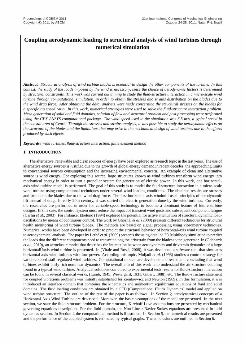
The assumptions of the solid model used in the ANSYS program are: the differential element is considered thin inaccording with the Kirchhoff-Love bending theory and the rotatory inertia effect in plane is not considered. For a finiteshell element approach, the flat elements are not all coplanar where the meet at a node. Isoparametric shell elements canalso be obtained by starting with a solid elastic element and reducing degrees of freedom. In Fig. 2, a shell element isdescribe by degrees of freedom representation and general state of Stress.
Figure 2. Shell Differential Element (Bettig, 2002).
The equations for bending plate in a spatial coordinate system (x, y, z) are written as:
D
(∂4uz
∂x4+ 2
∂4uz
∂x2∂y2+
∂4uz
∂y4
)= q (1)
whereuz is the transversal displacement,q is the external pressure loading andD is the flexural rigidity done by:
D =Et3
12 (1− ν2)(2)
wheret is the thickness of the plate,E is the Young’s modulus andν is the Poisson’s ratio.The longitudinal displacements can be related by Eq. (3) and (4).
G∇2ux +G
(1− 2ν)∂e
∂x= fx (3)
G∇2uy +G
(1− 2ν)∂e
∂y= fy (4)
whereux anduy are the longitudinal displacements and the force termsfx andfy are the longitudinal loadings inx andy directions, respectively. The termG is the Shear Modulus ande represents the solid dilatation done by:
e =∂ux
∂x+
∂uy
∂y+
∂uz
∂z(5)
3.2 The Fluid Dynamics Equations
The methodology used by the software CFX-ANSYS for obtaining the velocity and pressure fields is to solve theNavier-Stokes equations and mass conservation for the fluid motion based on the continuum hypothesis. The Navier-Stokes equations represent an application of Newton’s second law on fluid mechanics and relate the rate of change ofmomentum with the pressure gradient, viscosity and velocity field. The equations (6) through (8) are the Navier-Stokesequations for an infinitesimal fluid element of massdm in cartesian coordinates system.
ρDvx
Dt= ρgx − ∂P
∂x+
∂
∂x
[µ
(2∂vx
∂x− 2
3∇ · ~V
)]+
∂
∂y
[µ
(∂vx
∂y+
∂vy
∂x
)]+
∂
∂z
[µ
(∂vx
∂z+
∂vz
∂x
)](6)
ρDvy
Dt= ρgy − ∂P
∂y+
∂
∂y
[µ
(2∂vy
∂y− 2
3∇ · ~V
)]+
∂
∂x
[µ
(∂vy
∂x+
∂vx
∂y
)]+
∂
∂z
[µ
(∂vy
∂z+
∂vz
∂y
)](7)
ρDvz
Dt= ρgz − ∂P
∂z+
∂
∂z
[µ
(2∂vz
∂z− 2
3∇ · ~V
)]+
∂
∂x
[µ
(∂vz
∂x+
∂vx
∂z
)]+
∂
∂y
[µ
(∂vz
∂y+
∂vy
∂z
)](8)
The left term on each equation is the change of momentum,ρ being the fluid density,µ is the kinematic viscosityof the fluid, vx, vy andvz being the velocity components. The termP is the local thermodynamic pressure,∂P/∂x,
Proceedings of COBEM 2011Copyright c© 2011 by ABCM
21st International Congress of Mechanical EngineeringOctober 24-28, 2011, Natal, RN, Brazil
∂P/∂y and∂P/∂z are the pressure gradients to respect the cartesian directions,~g is the acceleration of gravity. The terminvolving the divergence of the velocity field represents the normal stress, and the other two terms multiplied by the partialderivatives represent the shear stresses.
This set of equations is non-linear, because the expressions of the stresses depend on the velocity field. Therefore, thesolution algorithm is iterative. For laminar flows, the first step of the solving process is to assume a value for the fluiddensity. Next, the velocity field is calculated through the equation of conservation of mass or continuity equation, Eq. (9).
∂ρ
∂t+∇ ·
(ρ~V
)= 0 (9)
where∂ρ/∂t is the transient term.Then, the velocity field is inserted into the Navier-Stokes equation and the pressure field is obtained. Therefore, it is
possible to relate the thermodynamic pressure with the density of the fluid through the expressions called equations ofstate. A new value for density is then found, and a new iteration begins. The process is then repeated until convergence isreached. In turbulent flows, fluctuations in the components of velocity occur, and these fluctuations cause additional shearstresses, called Reynolds stresses. These new stresses are added to the Navier-Stokes equations, and for its assessment,several methods and turbulence models have been developed lately.
4. COMPUTATIONAL PROCEDURE
In this paper, the solution was obtained by commercial tools. A Finite Element Code named ANSYS solves the integralmechanical equations for static conditions. Firstly, a rigid boundary for the wind axis turbine submerse on the fluid wasdesigned. In this context, the equations of the fluid domain were solved by using the CFX-Ansys Package (Carneiro,2011). The normal pressures field on the blades were obtained. These values represent the loading on the structuraldomain done by interface conditions, as described in Eq. (10).
∫
Γ
(pI · ndA) =∫
Γ
(σ · ndA) (10)
wherep represents the normal pressure field,n is the normal unitary vector to the interface fluid-structureΓ, I is theidentity matrix andσ is the stress tensor of the structure.
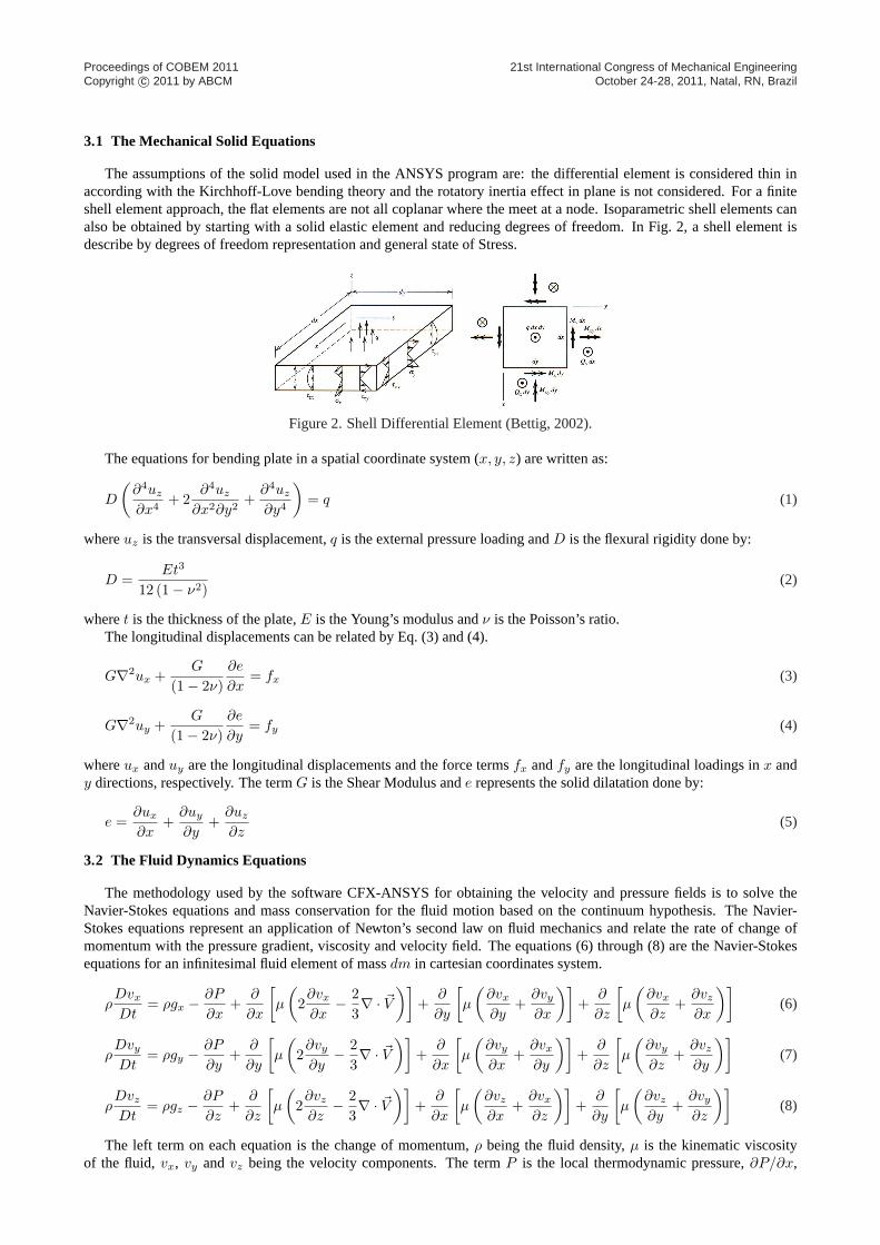
The normal pressure functionp(x, y, z) was determined to longz axis and its values interpolated on structural mesh.After, these results are combined by the ANSYS Multyphysics solver (ANSYS, 1995). In this work, the solution forthe structural problem was determined. The description of CFX-ANSYS interaction strategy to obtain the solutions ispresented in Fig. 3.
Figure 3. Solution algorithm of the CFX-ANSYS package.
In order to solve the fluid-structure problem, it is necessary calculate the elementary matrices and assemblage theglobal matrices (equivalent mass and stiffness matrices) of the system. Therefore, solid displacements are obtained bycombination of velocity-pressure field solutions for equilibrium condition and transferring the equivalents loads amongdifferent domains. The fluid problem solution can be determined by interactive methods to solve the nonlinear equationsystem. In the next section, a numerical model of a micro-scale wind turbine is presented. The performance is evaluatedby several numerical tests.
Proceedings of COBEM 2011Copyright c© 2011 by ABCM
21st International Congress of Mechanical EngineeringOctober 24-28, 2011, Natal, RN, Brazil
5. NUMERICAL RESULTS
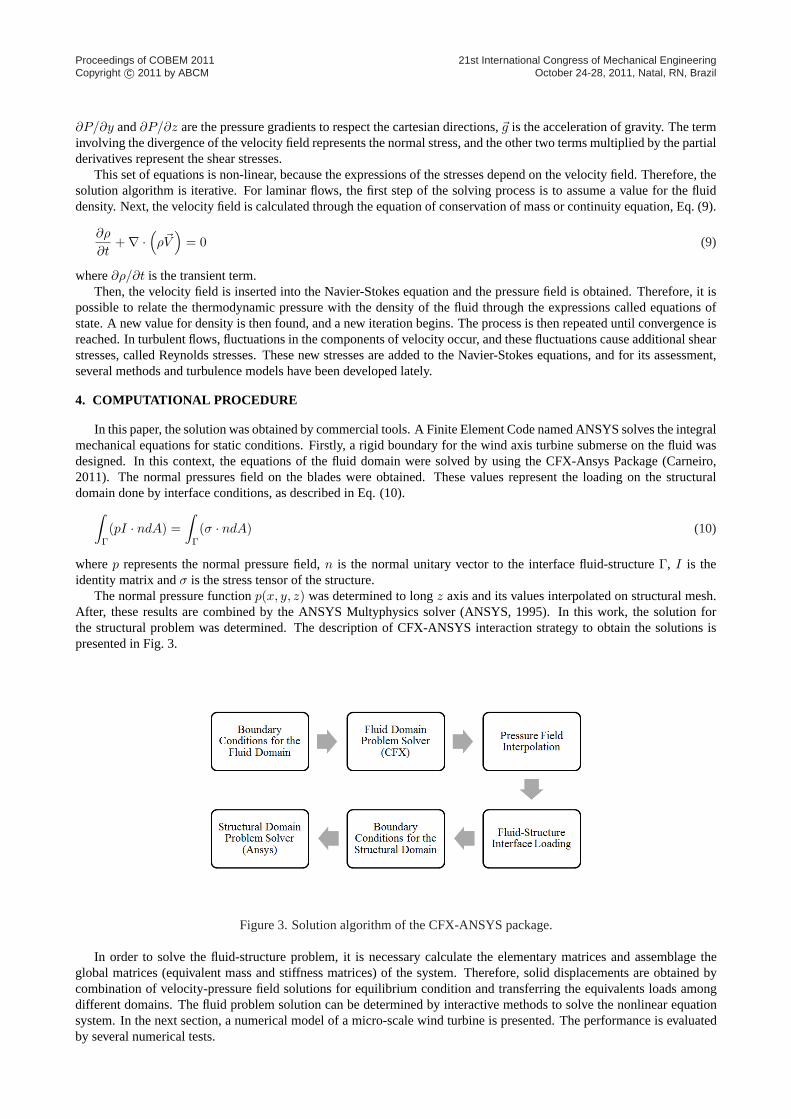
In this section, one presents the numerical results obtained for a fluid-structure interaction analysis. The numeric testswere performed by coupling the wind air that passes on the structure of a micro-scale wind turbine. Firstly, the pressurefield through the chordwise direction and one pressure line in the blade spanwise direction were obtained through CFDanalysis as found in (Royes, 2009). The pressure field in the chordwise direction is shown in Fig. 4.
Figure 4. Flotran: Pressure Contours.
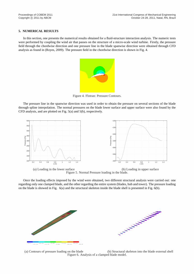
The pressure line in the spanwise direction was used in order to obtain the pressure on several sections of the bladethrough spline interpolation. The normal pressures on the blade lower surface and upper surface were also found by theCFD analysis, and are plotted on Fig. 5(a) and 5(b), respectively.
0.2 0.4 0.6 0.8 1 1.2 1.4100
150
200
250
300
350
400
450
500
z (m)
Pre
ssur
e (P
a)
(a) Loading in the lower surface
0.2 0.4 0.6 0.8 1 1.2 1.4−400
−350
−300
−250
−200
−150
−100
z (m)
Pre
ssur
e (P
a)
(b) Loading in upper surfaceFigure 5. Normal Pressure loading in the blade.
Once the loading effects imposed by the wind were obtained, two different structural analysis were carried out: oneregarding only one clamped blade, and the other regarding the entire system (blades, hub and tower). The pressure loadingon the blade is showed in Fig. 6(a) and the structural skeleton inside the blade shell is presented in Fig. 6(b).
-396.1-301.196
-206.291-111.387
-16.48278.422
173.327268.231
363.136458.04
(a) Contours of pressure loading on the blade
(b) Structural skeleton into the blade external shellFigure 6. Analysis of a clamped blade model.
Proceedings of COBEM 2011Copyright c© 2011 by ABCM
21st International Congress of Mechanical EngineeringOctober 24-28, 2011, Natal, RN, Brazil
The material of the blade exterior surface, Fig. 6(a), is aluminium, and the structural skeleton, Fig. 6(b), is wood. Thematerial properties are given in Tab. 1.
Table 1. Material properties.
Properties Aluminium WoodElasticity Modulus (GPa) 200 18
Poisson Ratio 0.3 0.3Density(kg/m3) 2100 785
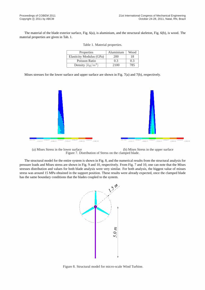
Mises stresses for the lower surface and upper surface are shown in Fig. 7(a) and 7(b), respectively.
389.593.151E+07
.303E+07.454E+07
.606E+07.757E+07
.909E+07.106E+08
.121E+08.136E+08
(a) Mises Stress in the lower surface
389.593.151E+07
.303E+07.454E+07
.606E+07.757E+07
.909E+07.106E+08
.121E+08.136E+08
(b) Mises Stress in the upper surfaceFigure 7. Distribution of Stress on the clamped blade.
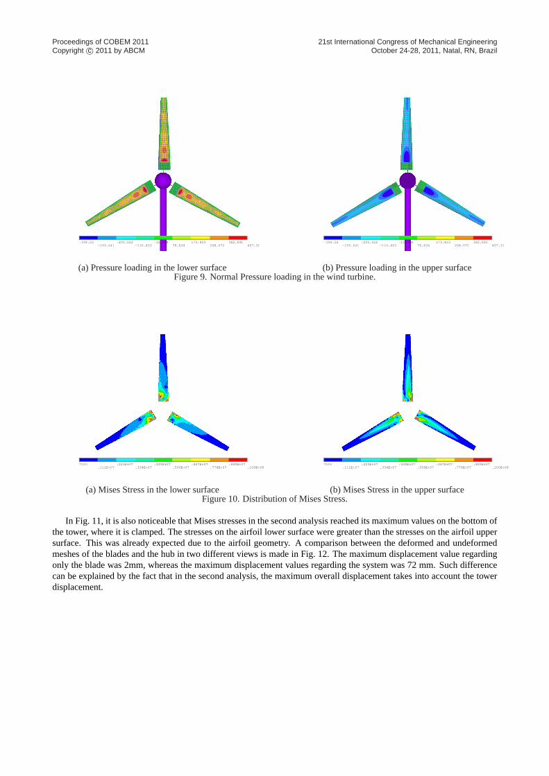
The structural model for the entire system is shown in Fig. 8, and the numerical results from the structural analysis forpressure loads and Mises stress are shown in Fig. 9 and 10, respectively. From Fig. 7 and 10, one can note that the Misesstresses distribution and values for both blade analysis were very similar. For both analysis, the biggest value of missesstress was around 15 MPa obtained in the support position. These results were already expected, once the clamped bladehas the same boundary conditions that the blades coupled to the system.
Figure 8. Structural model for micro-scale Wind Turbine.
Proceedings of COBEM 2011Copyright c© 2011 by ABCM
21st International Congress of Mechanical EngineeringOctober 24-28, 2011, Natal, RN, Brazil
-394.26-299.641
-205.022-110.403
-15.78478.834
173.453268.072
362.691457.31
(a) Pressure loading in the lower surface
-394.26-299.641
-205.022-110.403
-15.78478.834
173.453268.072
362.691457.31
(b) Pressure loading in the upper surfaceFigure 9. Normal Pressure loading in the wind turbine.
7000.112E+07
.223E+07.334E+07
.445E+07.556E+07
.667E+07.778E+07
.889E+07.100E+08
(a) Mises Stress in the lower surface
7000.112E+07
.223E+07.334E+07
.445E+07.556E+07
.667E+07.778E+07
.889E+07.100E+08
(b) Mises Stress in the upper surfaceFigure 10. Distribution of Mises Stress.
In Fig. 11, it is also noticeable that Mises stresses in the second analysis reached its maximum values on the bottom ofthe tower, where it is clamped. The stresses on the airfoil lower surface were greater than the stresses on the airfoil uppersurface. This was already expected due to the airfoil geometry. A comparison between the deformed and undeformedmeshes of the blades and the hub in two different views is made in Fig. 12. The maximum displacement value regardingonly the blade was 2mm, whereas the maximum displacement values regarding the system was 72 mm. Such differencecan be explained by the fact that in the second analysis, the maximum overall displacement takes into account the towerdisplacement.

Proceedings of COBEM 2011Copyright c© 2011 by ABCM
21st International Congress of Mechanical EngineeringOctober 24-28, 2011, Natal, RN, Brazil
7000.167E+07
.334E+07.500E+07
.667E+07.834E+07
.100E+08.117E+08
.133E+08.150E+08
Figure 11. Mises Stress in the full structural model.
(a) Undeformed Mesh - Lateral Vision (b) Deformed Mesh - Lateral Vision
(c) Undeformed Mesh - Frontal Vision (d) Deformed Mesh - Frontal VisionFigure 12. Displacements for the Wind Turbine Model.
6. CONCLUSIONS
In this work, several numerical tests have been performed. One typical airfoil for the blade found in a micro-scaleHorizontal Axis Wind Turbine has been tested. The first test was conceived as a clamped beam. The second test wasperformed as full structural model, involving blades, tower and hub. For mesh generation, shell elements have been used.Coupling system was performed by combining CFD results and structural analysis. The finite element formulation testedfor CFX-Ansys software show good results for the proposed test problems. Results form structural analysis were usedto predict the global resistance of the system with respect to the wind drag. The displacements results were evaluatedand large displacements were obtained. Based on the Static Failure Theory, the Mises stresses obtained did not reach theallowed limit. Therefore, it can be stated that the employed materials are suitable for the micro scale wind turbines design.
Proceedings of COBEM 2011Copyright c© 2011 by ABCM
21st International Congress of Mechanical EngineeringOctober 24-28, 2011, Natal, RN, Brazil
7. ACKNOWLEDGEMENTS
The authors would like to thank CNPq (Conselho Nacional de Pesquisa), Capes (Coordenação de Aperfeiçoamento dePessoal de Nível Superior) and Funcap (Fundação Cearence de apoio à Pesquisa) for financial support for this work.
8. REFERENCES
ANSYS, 1995.User Manual, Vol. 1, 2, 3, 4, 5.Bettig, B., 2002.Lectures in Introduction to Finite Element Analysis. MichiganTech, USA.Burton, T., Sharpe, D., Jenkins, N. and Bossanyi, E., 2001.Wind Energy Handbook. John Wiley and Sons, West Sussex,
England.Carlin, P.W., Laxson, A.S. and Muljadi, E.B., 2003. “The history and state of the art of variable-speed wind turbine
technology”.Wind Energy, Vol. 6, pp. 129–159.Carneiro, F.O.M., 2011.Levantamento de curvas de eficiência de aerogeradores de 3m de diâmetro utilizando modelos
de turbulência RANS de uma e duas equações comparação experimental. Master’s thesis, Universidade Federal doCeará - UFC.
Ekelund, T., 1994. “Control of variable speed wind turbines in a broad range of wind speeds”.Technical Report NUTEK-VIND-94-9, Swedish National Board for Industrial and Technical Development (NUTEK).
Gebhardt, C., Veluri, B., Preidikman, S., Jensen, H. and Massa, J., 2010. “Numerical simulations of the aerolasticbehavior of large horizontal-axis wind turbines: The drivetrain case”. InProceedings of Mecánica Computacional- XXXI Iberian Latin-American Congress on Computational Methods in Engineering - XXXI Cilamce, Buenos Aires.Vol. Vol XXIX, pp. 949–967.
Ghoshal, A., Sundaresan, M.J., Schulz, M.J. and Pai, P.F., 2000. “Structural health monitoring techniques for wind turbineblades”.Journal of Wind Engineering and Industrial Aerodynamics, Vol. 85, pp. 309–324.
Gibert, R., 1988.Vibrations des Structures - Interactions avec les fluids - Sources d’excitaion aléatoires. Eyrolles, Paris,France.
Lamb, M., 1945.Hidrodynamics. Dover Publications.Lethé, G., Cuyper, J.D., Kang, J., Furman, M. and Kading, D., 2009. “Simulating dynamics, durability and noise emission
of wind turbines in a single cae environment”.Journal of Mechanical Science and Technology, Vol. 23, pp. 1089–1093.Muljadi, E., Pierce, K. and Migliore, P., 1998. “Control strategy for variable-speed, stall-regulated wind turbines”.
Technical Report NREL/CP-500-24311.Park, K.C., 1983. “Stabilization of partitioned solution procedure for pore fluid-soil interaction analysis”.International
Journal for Numerical Methods in Engineering, Vol. 19, pp. 1669–1673.Royes, S.M., 2009.Estudio comparativo teórico de la evolución 2008/2009 de los alerones delanteros de Formula 1.
Master’s thesis, Universitat Politècnica de Catalunya.Vitale, A.J. and Rossi, A.P., 2008. “Software tool for horizontal-axis wind turbine simulation”.International Journal of
Hydrogen Energy, Vol. 33, pp. 3460–3465.Westergard, H., 1931. “Water pressures on dams during earthquaques effects”. InTransactions of ASCE. Vol. 98.Zienkiewicz, O.C. and Newton, E., 1969. “Coupled vibrations of a compressible fluid”. InProceedings of International
Symposium on Finite Elements Techniques. pp. 359–379.Zienkiewicz, O.C., Paul, D.K. and Chan, A.H.C., 1988. “Unconditionally stable staggered solution procedure for soil-pore
fluid interaction problems”.International Journal for Numerical Methods in Engineering, Vol. 26, pp. 1039–1055.
9. Responsibility notice
The author(s) is (are) the only responsible for the printed material included in this paper