cotton belt regional rail - dart.org belt regional rail ... table of supporting engineering...
TRANSCRIPT
Prepared for Dallas Area Rapid Transit General Planning Consultant Managed by URS Corporation
Cotton Belt Regional Rail 5% Preliminary Engineering Design Report
August 26, 2013
Final

Cotton Belt Regional Rail
Final 5% Preliminary Engineering Design Report i
Revision Record
Project/Report Name: Cotton Belt PE/EIS URS Project Number: 25338804
PM: Dan Meyers PIC: Jerry Smiley
Revision Number: Date:
Draft
Final
Originator: Peng Zhao Date: 26 August 2013
Comments by:
Distribution Name Department Firm
John Hoppie DART Rail Planning DART
Cotton Belt Regional Rail
Final 5% Preliminary Engineering Design Report ii
TABLE OF CONTENTS
1.0 INTRODUCTION .................................................................................................................... 1
2.0 DESCRIPTION OF COTTON BELT CORRIDOR ......................................................................... 1
2.1 Project Description ............................................................................................................................ 1
2.2 Reference Documents ....................................................................................................................... 1
2.2.1 Aerial Photography and Base Mapping ....................................................................................... 2
3.0 DESIGN CRITERIA .................................................................................................................. 2
4.0 HORIZONTAL AND VERTICAL ALIGNMENT ........................................................................... 3
4.1 Horizontal Alignment......................................................................................................................... 4
4.1.1 Section 1 - CB1 ............................................................................................................................. 5
4.1.2 Section 2 – CB2............................................................................................................................. 6
4.1.3 Section 3 – CB3............................................................................................................................. 6
4.2 Vertical Alignment ............................................................................................................................. 8
4.2.1 Section 1 - CB1 ............................................................................................................................. 8
4.2.2 Section 2 – CB2............................................................................................................................. 8
4.2.3 Section 3 – CB3............................................................................................................................. 9
4.3 Trackwork 11
5.0 RIGHT-OF-WAY ..................................................................................................................... 14
6.0 UTILITY MODIFICATIONS ...................................................................................................... 15
6.1 Section CB-1 ....................................................................................................................................... 15
6.2 Section CB-2 ....................................................................................................................................... 17
6.3 Section CB-3 ....................................................................................................................................... 18
7.0 BRIDGE AND STRUCTURAL DESIGN ..................................................................................... 21
7.1 Bridge Design ..................................................................................................................................... 21
7.2 Section 1 - CB1 ................................................................................................................................... 22
7.3 Section 2 - CB2 ................................................................................................................................... 23
7.4 Section 3 - CB3 ................................................................................................................................... 24
8.0 DRAINAGE ......................................................................................................................... 26
8.1 Section CB-1 ....................................................................................................................................... 27
8.1.1 Overview ...................................................................................................................................... 27
8.1.2 Areas of Importance .................................................................................................................... 28
8.2 Section CB-2 ....................................................................................................................................... 28
8.2.1 Overview ...................................................................................................................................... 28
8.2.2 Areas of Importance .................................................................................................................... 28
8.2.3 Hydraulics ..................................................................................................................................... 28
8.3 Section CB-3 ....................................................................................................................................... 30
8.3.1 Overview ...................................................................................................................................... 30
8.3.2 Areas of Importance .................................................................................................................... 30
8.3.3 Hydraulics ..................................................................................................................................... 30
9.0 STATION DESIGN .................................................................................................................. 33
9.1 Section CB-1 ....................................................................................................................................... 33
9.2 Section CB-2 ....................................................................................................................................... 33
9.3 Section CB-3 ....................................................................................................................................... 34
Cotton Belt Regional Rail
Final 5% Preliminary Engineering Design Report iii
10.0 TRANSPORTATION CROSSINGS .......................................................................................... 34
11.0 ENVIRONMENTAL CONSIDERATIONS ................................................................................ 37
11.1 Land Use…. ...................................................................................................................................... 37
11.2 Socioeconomic Characteristics including Environmental Justice .................................................... 38
11.3 Acquisitions and Displacements ...................................................................................................... 38
11.4 Parks and Recreational Facilities ..................................................................................................... 38
11.5 Cultural Resources ........................................................................................................................... 38
11.6 Geology….. 39
11.7 Floodplains ...................................................................................................................................... 39
11.8 Water Quality .................................................................................................................................. 40
11.9 Noise and Vibration ......................................................................................................................... 40
11.10 Air Quality ...................................................................................................................................... 41
11.11 Hazardous Materials ...................................................................................................................... 41
11.12 Water Resources ........................................................................................................................... 42
11.13 Biological Resources ...................................................................................................................... 42
12.0 GEOTECHNICAL CONSIDERATIONS .................................................................................. 43
13.0 SYSTEM ELEMENTS ........................................................................................................... 43
13.1 Positive Train Control ...................................................................................................................... 44
13.2 Wayside Signals ............................................................................................................................... 44
13.3 Highway Grade Crossing Signals ...................................................................................................... 45
13.4 Communication Systems ................................................................................................................. 45
LIST OF FIGURES
Figure 4-1 Corridor Section Breakdown .................................................................................................... 4
Figure 4-2 Typical Section of Track Structure .......................................................................................... 12
Figure 4-3 Typical Section of Direct Fixation Track ................................................................................. 13
LIST OF TABLES Table 6-1 Cotton Belt Phase I Trench Area Utility Crossings .................................................................. 19
Table 10-1 Summary of Grade Separation Thresholds ........................................................................... 36
LIST OF APPENDICES Appendix A: Cotton Belt Existing Utility/Crossing Lists ................................................................. 47
Appendix B: Cotton Belt Transportation Crossings ....................................................................... 62
Appendix C: Existing Freight Operations Exhibit ........................................................................... 67
Appendix D: Traffic Volumes ..................................................................................................... 6968
Appendix E: Bridge Structures List ............................................................................................ 7776
Appendix F: Table of Supporting Engineering Documents ........................................................ 7978
Cotton Belt Regional Rail
Final 5% Preliminary Engineering Design Report 1
1.0 INTRODUCTION Dallas Area Rapid Transit (DART) is preparing preliminary engineering plans for the Cotton Belt
Regional Rail Corridor from Dallas/Fort Worth International Airport (DFW Airport) to its
terminus in Plano. When completed, the regional passenger rail within the Cotton Belt Corridor
will provide service to DFW Airport, air passengers and other commuters in the North Central
Texas region. In addition, it is proposed to provide connection to the DART Orange, Red and
Green lines. Once the preliminary engineering is completed, DART and its partners will have a
preferred alignment for the Cotton Belt Regional Rail.
2.0 DESCRIPTION OF COTTON BELT CORRIDOR The Cotton Belt Corridor is an existing east/west freight rail corridor for which a regional
passenger rail is being proposed. The DART Cotton Belt project corridor is located on DART right-
of-way (ROW) and runs from just north of DFW Airport to central Plano. It passes through Collin,
Dallas and Tarrant Counties and includes the cities of Grapevine, Coppell, Carrollton, Addison,
Dallas, Richardson and Plano.
2.1 Project Description
The Cotton Belt project corridor is approximately 26 miles in length and generally runs in a
northeasterly direction from north of DFW Airport to its proposed terminus in Plano. The
proposed passenger rail will largely follow the existing freight rail within the corridor. The
corridor moves northeasterly, passing through an industrial area in Coppell. It then parallels Belt
Line Road through Coppell into Carrollton. The area adjacent to the Carrollton segment consists
of a mix of commercial and residential developments. As the corridor crosses IH 35E, it passes
under the DART Green Line and then veers away from Belt Line Road. It runs through residential
and industrial areas moving east along the southern edge of Addison Airport in Addison. It
crosses over the Dallas North Tollway (DNT) and enters Dallas City Limits going through mostly
residential areas in North Dallas. It continues east, entering Richardson, and runs on the north
side of the University of Texas - Dallas (UTD) campus. From here to its terminus it runs mostly
through commercial areas. In north Richardson and Plano, it traverses east over US 75 and
under the DART Red Line. Two alternatives, the North Alternative and the South Alternative are
included in the east terminus alignment alternative study.
2.2 Reference Documents
Data was collected from DART, Fort Worth T, North Central Texas Council of Governments
(NCTCOG), Texas Department of Transportation (TxDOT) and other entities to identify major
constraints and possible conflicts within the corridor. There are several projects in the
planning/design phase within the corridor area. Information shown for these projects is subject
to change and will require continued coordination as the projects advance. Project documents
that have been collected include the following:
City of Carrollton:
Carrollton Downtown Rail Station Master Plan Phase I 2006
Carrollton Downtown Rail Station Master Plan Phase II 2009
Cotton Belt Regional Rail
Final 5% Preliminary Engineering Design Report 2
City of Dallas:
Cypress Waters Development 2010
City Council Resolution No. 061835 June 2006
Dickerson Street January 2009
City of Plano
Cotton Belt Corridor Study April 2010
Fort Worth T
TEX Rail Project RFP January 2013
NCTCOG
Conceptual Engineering & Funding Study April 2010
NTTA
PGBT Segment IV Bridge, Utilities, Roadway Plan Set October 2002
TxDOT:
DFW Connector
IH 35E Bridge, Utilities, Roadway Plan Set February 1970
IH 35E Reconstruction Preliminary Engineering Plans Fall 2010
IH 35E Draft Design-Build Construction Plans by AGL Constructors July 2013
Luna Road Reconstruction June 1999
US 75/PGBT Interchange November 2012
2.2.1 Aerial Photography and Base Mapping The aerial photographs used in the plans were obtained from two sources. On March 29, 2010
the corridor was flown by Martinez Geospatial. This resulted in aerial photography that follows
the Cotton Belt corridor with imagery showing 1,000 feet to each side. The remaining aerial
images are from the NCTCOG. These images are from a spring 2007 flight. It is strongly
recommended that DART conduct aerial mapping as well as planimetric updates along the
preliminary engineering alignment during final design. The updated base mapping along with
current planimetrics would produce the most accurate final alignment design and earthwork
quantities.
3.0 DESIGN CRITERIA The alignment alternatives were developed in accordance with American Railway Engineering
and Maintenance-of-Way Association (AREMA) standards, DART Design Criteria Manual and the
draft Cotton Belt Regional Rail Design Criteria Manual. Any proposed street or utility
modifications will be designed in accordance with DART’s design criteria or the local jurisdiction
design criteria/standards: the more stringent standards will prevail.
Continued development of the proposed design will require the selection of a design vehicle to
establish the appropriate design criteria.

Cotton Belt Regional Rail
Final 5% Preliminary Engineering Design Report 3
Refer to Appendix F for the Cotton Belt engineering documents that supported the 5%
Preliminary Engineering design.
4.0 HORIZONTAL AND VERTICAL ALIGNMENT The design team divided the entire project corridor into three separate sections as shown in
Figure 4-1. Section 1 begins at DFW Airport and ends at the Elm Fork of the Trinity River. Section
2 begins at the Elm Fork and extends through Downtown Carrollton, terminating just east of the
DNT at the southbound frontage road. Section 3 begins at DNT southbound frontage road and
extends to the Terminal Station just east of US 75. The separation of the corridor allowed the
design team to work simultaneously on the project alignments, which in turn shortened the
design timeline. The 5% submittal set will include three separate volumes of plans for DART
review.

Cotton Belt Regional Rail
Final 5% Preliminary Engineering Design Report 4
Fig
ure
4-1
Co
rrid
or
Se
ctio
n B
rea
kd
ow
n
Cotton Belt Regional Rail
Final 5% Preliminary Engineering Design Report 5
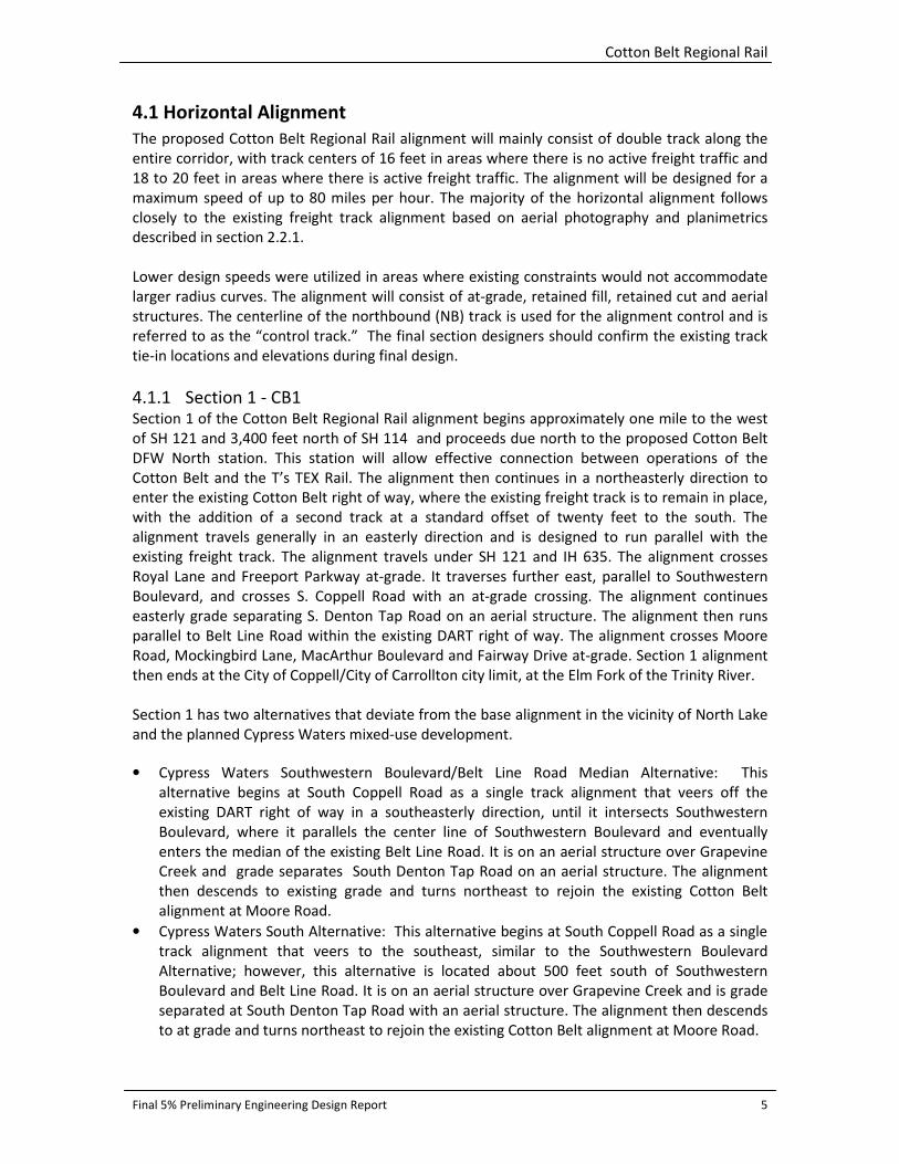
4.1 Horizontal Alignment
The proposed Cotton Belt Regional Rail alignment will mainly consist of double track along the
entire corridor, with track centers of 16 feet in areas where there is no active freight traffic and
18 to 20 feet in areas where there is active freight traffic. The alignment will be designed for a
maximum speed of up to 80 miles per hour. The majority of the horizontal alignment follows
closely to the existing freight track alignment based on aerial photography and planimetrics
described in section 2.2.1.
Lower design speeds were utilized in areas where existing constraints would not accommodate
larger radius curves. The alignment will consist of at-grade, retained fill, retained cut and aerial
structures. The centerline of the northbound (NB) track is used for the alignment control and is
referred to as the “control track.” The final section designers should confirm the existing track
tie-in locations and elevations during final design.
4.1.1 Section 1 - CB1 Section 1 of the Cotton Belt Regional Rail alignment begins approximately one mile to the west
of SH 121 and 3,400 feet north of SH 114 and proceeds due north to the proposed Cotton Belt
DFW North station. This station will allow effective connection between operations of the
Cotton Belt and the T’s TEX Rail. The alignment then continues in a northeasterly direction to
enter the existing Cotton Belt right of way, where the existing freight track is to remain in place,
with the addition of a second track at a standard offset of twenty feet to the south. The
alignment travels generally in an easterly direction and is designed to run parallel with the
existing freight track. The alignment travels under SH 121 and IH 635. The alignment crosses
Royal Lane and Freeport Parkway at-grade. It traverses further east, parallel to Southwestern
Boulevard, and crosses S. Coppell Road with an at-grade crossing. The alignment continues
easterly grade separating S. Denton Tap Road on an aerial structure. The alignment then runs
parallel to Belt Line Road within the existing DART right of way. The alignment crosses Moore
Road, Mockingbird Lane, MacArthur Boulevard and Fairway Drive at-grade. Section 1 alignment
then ends at the City of Coppell/City of Carrollton city limit, at the Elm Fork of the Trinity River.
Section 1 has two alternatives that deviate from the base alignment in the vicinity of North Lake
and the planned Cypress Waters mixed-use development.
• Cypress Waters Southwestern Boulevard/Belt Line Road Median Alternative: This
alternative begins at South Coppell Road as a single track alignment that veers off the
existing DART right of way in a southeasterly direction, until it intersects Southwestern
Boulevard, where it parallels the center line of Southwestern Boulevard and eventually
enters the median of the existing Belt Line Road. It is on an aerial structure over Grapevine
Creek and grade separates South Denton Tap Road on an aerial structure. The alignment
then descends to existing grade and turns northeast to rejoin the existing Cotton Belt
alignment at Moore Road.
• Cypress Waters South Alternative: This alternative begins at South Coppell Road as a single
track alignment that veers to the southeast, similar to the Southwestern Boulevard
Alternative; however, this alternative is located about 500 feet south of Southwestern
Boulevard and Belt Line Road. It is on an aerial structure over Grapevine Creek and is grade
separated at South Denton Tap Road with an aerial structure. The alignment then descends
to at grade and turns northeast to rejoin the existing Cotton Belt alignment at Moore Road.
Cotton Belt Regional Rail
Final 5% Preliminary Engineering Design Report 6
Both of these alternatives require Belt Line Road to be relocated and reconfigured. The
Southwestern Boulevard/Belt Line Road Median alternative minimizes potential ROW takes for
the properties south of the Belt Line Road. However, the alignment along Southwestern Blvd
may cause traffic issues for the elementary school north of Southwestern Boulevard during
school drop off and pick-up hours. The South Alternative avoids the potential traffic issues in the
school zone but it requires substantial ROW acquisition south of Belt Line Road and
Southwestern Blvd. The Southwestern Boulevard/Belt Line Road alternative was included in the
Final 5% Preliminary Engineering design as the Cypress Waters Alternative.
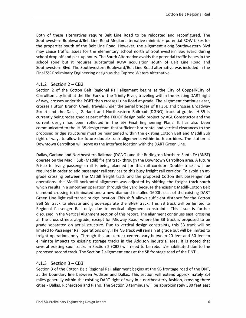
4.1.2 Section 2 – CB2 Section 2 of the Cotton Belt Regional Rail alignment begins at the City of Coppell/City of
Carrollton city limit at the Elm Fork of the Trinity River, traveling within the existing DART right
of way, crosses under the PGBT then crosses Luna Road at-grade. The alignment continues east,
crosses Hutton Branch Creek, travels under the aerial bridges of IH 35E and crosses Broadway
Street and the Dallas, Garland and Northeastern Railroad (DGNO) track at-grade. IH-35 is
currently being redesigned as part of the TXDOT design build project by AGL Constructor and the
current design has been reflected in the 5% Final Engineering Plans. It has also been
communicated to the IH-35 design team that sufficient horizontal and vertical clearances to the
proposed bridge structures must be maintained within the existing Cotton Belt and Madill Sub
right of ways to allow for future double track alignments within both corridors. The station at
Downtown Carrollton will serve as the interface location with the DART Green Line.
Dallas, Garland and Northeastern Railroad (DGNO) and the Burlington Northern Santa Fe (BNSF)
operate on the Madill Sub (Madill) freight track through the Downtown Carrollton area. A future
Frisco to Irving passenger rail is being planned for this rail corridor. Double tracks will be
required in order to add passenger rail services to this busy freight rail corridor. To avoid an at-
grade crossing between the Madill freight track and the proposed Cotton Belt passenger rail
operations, the Madill horizontal alignment was adjusted by shifting the freight track south
which results in a smoother operation through the yard because the existing Madill-Cotton Belt
diamond crossing is eliminated and a new diamond installed 1600ft east of the existing DART
Green Line light rail transit bridge location. This shift allows sufficient distance for the Cotton
Belt SB track to elevate and grade-separate the BNSF track. This SB track will be limited to
Regional Passenger Rail only, due to vertical alignment constraints. This issue is further
discussed in the Vertical Alignment section of this report. The alignment continues east, crossing
all the cross streets at-grade, except for Midway Road, where the SB track is proposed to be
grade separated on aerial structure. Due to vertical design constraints, this SB track will be
limited to Passenger Rail operations only. The NB track will remain at grade but will be limited to
freight operations only. Through this area, track centers vary between 20 feet and 30 feet to
eliminate impacts to existing storage tracks in the Addison industrial area. It is noted that
several existing spur tracks in Section 2 (CB2) will need to be rebuilt/rehabilitated due to the
proposed second track. The Section 2 alignment ends at the SB frontage road of the DNT.
4.1.3 Section 3 – CB3 Section 3 of the Cotton Belt Regional Rail alignment begins at the SB frontage road of the DNT,
at the boundary line between Addison and Dallas. This section will extend approximately 8.4
miles generally within the existing DART right of way in a northeasterly fashion, crossing three
cities - Dallas, Richardson and Plano. The Section 3 terminus will be approximately 580 feet east
Cotton Belt Regional Rail
Final 5% Preliminary Engineering Design Report 7
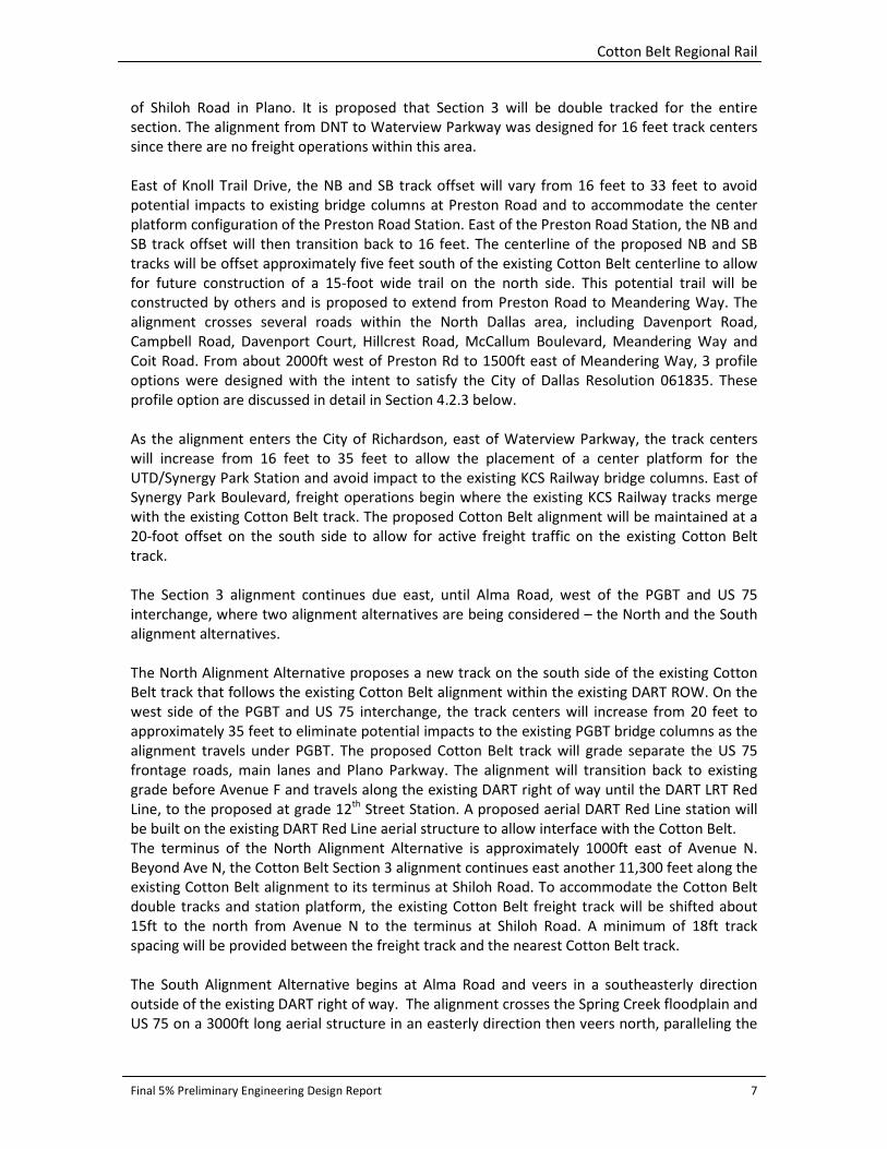
of Shiloh Road in Plano. It is proposed that Section 3 will be double tracked for the entire
section. The alignment from DNT to Waterview Parkway was designed for 16 feet track centers
since there are no freight operations within this area.
East of Knoll Trail Drive, the NB and SB track offset will vary from 16 feet to 33 feet to avoid
potential impacts to existing bridge columns at Preston Road and to accommodate the center
platform configuration of the Preston Road Station. East of the Preston Road Station, the NB and
SB track offset will then transition back to 16 feet. The centerline of the proposed NB and SB
tracks will be offset approximately five feet south of the existing Cotton Belt centerline to allow
for future construction of a 15-foot wide trail on the north side. This potential trail will be
constructed by others and is proposed to extend from Preston Road to Meandering Way. The
alignment crosses several roads within the North Dallas area, including Davenport Road,
Campbell Road, Davenport Court, Hillcrest Road, McCallum Boulevard, Meandering Way and
Coit Road. From about 2000ft west of Preston Rd to 1500ft east of Meandering Way, 3 profile
options were designed with the intent to satisfy the City of Dallas Resolution 061835. These
profile option are discussed in detail in Section 4.2.3 below.
As the alignment enters the City of Richardson, east of Waterview Parkway, the track centers
will increase from 16 feet to 35 feet to allow the placement of a center platform for the
UTD/Synergy Park Station and avoid impact to the existing KCS Railway bridge columns. East of
Synergy Park Boulevard, freight operations begin where the existing KCS Railway tracks merge
with the existing Cotton Belt track. The proposed Cotton Belt alignment will be maintained at a
20-foot offset on the south side to allow for active freight traffic on the existing Cotton Belt
track.
The Section 3 alignment continues due east, until Alma Road, west of the PGBT and US 75
interchange, where two alignment alternatives are being considered – the North and the South
alignment alternatives.
The North Alignment Alternative proposes a new track on the south side of the existing Cotton
Belt track that follows the existing Cotton Belt alignment within the existing DART ROW. On the
west side of the PGBT and US 75 interchange, the track centers will increase from 20 feet to
approximately 35 feet to eliminate potential impacts to the existing PGBT bridge columns as the
alignment travels under PGBT. The proposed Cotton Belt track will grade separate the US 75
frontage roads, main lanes and Plano Parkway. The alignment will transition back to existing
grade before Avenue F and travels along the existing DART right of way until the DART LRT Red
Line, to the proposed at grade 12th
Street Station. A proposed aerial DART Red Line station will
be built on the existing DART Red Line aerial structure to allow interface with the Cotton Belt.
The terminus of the North Alignment Alternative is approximately 1000ft east of Avenue N.
Beyond Ave N, the Cotton Belt Section 3 alignment continues east another 11,300 feet along the
existing Cotton Belt alignment to its terminus at Shiloh Road. To accommodate the Cotton Belt
double tracks and station platform, the existing Cotton Belt freight track will be shifted about
15ft to the north from Avenue N to the terminus at Shiloh Road. A minimum of 18ft track
spacing will be provided between the freight track and the nearest Cotton Belt track.
The South Alignment Alternative begins at Alma Road and veers in a southeasterly direction
outside of the existing DART right of way. The alignment crosses the Spring Creek floodplain and
US 75 on a 3000ft long aerial structure in an easterly direction then veers north, paralleling the
Cotton Belt Regional Rail
Final 5% Preliminary Engineering Design Report 8
existing DART LRT Red Line tracks on the west side. The proposed PGBT Station will serve as an
interface with the existing DART Red Line station. The alignment then parallels the existing DART
Red Line on the west and travels due north under PGBT after which it grade separates Plano
Parkway and reduces from a double track to single track alignment that follows the existing spur
track alignment on the west of the DART Red Line due to limited right of way. The single track
alignment then curves east under the DART LRT Red Line aerial structure. For the South
Alternative, it is proposed that the 12th
Street Station will be an aerial platform to allow for ease
of access to the proposed DART Red Line aerial station. The terminus of the South Alignment
Alternative is approximately 1000ft east of Avenue N.
4.2 Vertical Alignment
4.2.1 Section 1 - CB1 The Cotton Belt Regional Rail Section 1 vertical alignment begins north of SH 114 on an aerial
structure over SH 114. This aerial structure will be designed and constructed by the Fort Worth T
as part of the TEX Rail project. This grade separation avoids impacts to Cottonwood Branch and
the associated floodplain. The profile gradually descends onto retained fill to existing grade
before the Cotton Belt DFW North Station. North of the station, the profile matches existing
grade closely and ties in with the existing Cotton Belt. The profile continues at-grade under the
existing aerial structures of SH 121 and IH 635. The profile closely matches the existing grade as
it crosses Royal Lane, Freeport Parkway, S. Coppell Road, and crosses over the Grapevine Creek
on an aerial structure. It is on retained fill until it crosses S. Denton Tap Road, where the SB track
is on a grade separated aerial structure and then descends back to at-grade for the crossing of
Moore Road. Due to active freight track operations, the NB track will remain at grade as it
crosses South Denton Tap Road. Continuing east, the Section 1 profile is on aerial structure
crossing Grapevine Creek and then crosses Mockingbird Lane, MacArthur Boulevard and Fairway
Drive at grade. The profile gradually ascends on retained fill to aerial structure over two
floodplains west of the Elm Fork of the Trinity River.
4.2.2 Section 2 – CB2 The vertical alignment of Section 2 starts on structure over the Elm Fork of the Trinity River. The
profile stays at-grade on retained fill until it crosses the second Elm Fork on aerial structure. The
alignment crosses beneath aerial structure of Segment IV of the PGBT and crosses Luna Road at
grade. The profile grade then ascends on retained fill and aerial structure to cross the Hutton
Branch Creek. The profile matches the existing grade as it continues east under IH 35E. The
proposed design build IH 35 E plans show that the existing frontage roads and Belt Line Road will
be elevated to grade separate the Cotton Belt and BNSF tracks, which allows the tracks to
remain at grade.
East of IH 35, the NB profile follows the existing Cotton Belt profile and crosses underneath the
DART LRT Green Line structures, crossing the existing DGNO Track and Denton Drive at grade as
it follows the existing Cotton Belt freight track. East of the proposed Downtown Carrollton
Station, the NB Cotton Belt track will cross Denton Drive at grade and will require two diamond
crossings when it intersects the realigned BNSF and DGNO tracks.
The SB profile differs from the NB profile design just east of the proposed Downtown Carrollton
Station and Denton Drive at-grade crossing. The SB profile begins to ascend steeply on retained
Cotton Belt Regional Rail
Final 5% Preliminary Engineering Design Report 9
fill and transitions to aerial structure to allow grade separation of the existing BNSF & DGNO
tracks. Farther east, the SB profile descends on retained fill and ties back to the existing track
elevation just east of Unnamed Tributary of Hutton Branch. The Section 2 profile then slowly
increases in grade following existing at-grade crossings at Perry Street, Josey Lane, Kelly
Boulevard, Marsh Lane and Surveyor Boulevard.
At Midway Road, the SB track will be limited to passenger operations only as it increases on a
3.43% grade to grade separate Midway Road, while the NB track remains at grade to allow
freight operations. Both NB and SB profiles crosses Addison Road, Quorum Drive and Spectrum
Drive and the DNT frontage roads at-grade. Section 2 terminates before the grade separation of
the DNT main lanes.
4.2.3 Section 3 – CB3 The Section 3 vertical alignment begins at the DNT frontage roads where it matches closely the
existing grade. The profile is grade separated over the main lanes of the DNT. The profile follows
the existing Cotton Belt profile closely until west of Preston Road, at which point 4 profile
options were studied (at grade, shallow trench, tunnel and deep trench). The deep trench
option was deemed unfeasible and therefore only the 3 remaining profile options were
considered. The limits of the profile options are based on Dallas City Council Resolution 061835,
also known as the Natinsky Plan, from 2,000 feet west of Preston Road to 1,500 feet east of
Meandering Way (approximate length of 2.60 miles).
Profile Option 1: At-Grade The At-Grade Option follows the existing Cotton Belt profile closely with consideration given to
maintaining vertical tangents at proposed station locations and at grade street crossings. There
will be 3 creek crossings and 7 at grade street crossings within this profile limit, with the last
street crossing being Dickerson Street which will be an at-grade crossing.
Profile Option 2: Shallow Trench The Shallow Trench option consists of a combination of open cut trench that is typically 4 to 12
feet below grade with 6 to 10 feet above-grade screen walls. Within the trench limits, there will
be three creek crossings (McKamy Branch, Osage Branch Crossing 1 and 2) and six grade
separated street crossings. The profile begins to descend to approximately 12 feet below grade
starting at 2,000 feet west of Preston Road. The profile crosses under the Preston Road Bridge,
and then ascends slightly to cross McKamy Branch Creek one foot above the existing conditions
100-year water surface elevation. East of McKamy Branch, the profile descends back into a five
to 12-foot open cut trench, with a depth that is just above the projected Osage Branch 100-year
water surface elevation on the north side of the tracks. Davenport Road, Campbell Road and
Davenport Court are all proposed to be elevated to provide 18’ minimum vertical clearance
above the tracks. East of Davenport Court, the profile crosses Osage Branch Crossing 1 and 2,
maintaining a one foot freeboard above the Post-Project 100-year water surface elevation. The
profile remains in a five to 12-foot deep trench crossing under Hillcrest Road, McCallum
Boulevard and Meandering Way. These 3 streets are proposed to be elevated above the tracks
to provide 18’ minimum vertical clearance. East of Meandering Way, the profile rises to match
the existing grade before Dickerson Street. The profile then crosses Dickerson Street at grade.

Cotton Belt Regional Rail
Final 5% Preliminary Engineering Design Report 10
Profile Option 3: Tunnel The tunnel profile includes a 0.7-mile west portal, a 0.3-mile east portal and a 1.6-mile double
barrel tunnel, with each barrel having a 26ft inside diameter. It is anticipated that the majority
of the soil classification within the tunnel limits will be limestone rock formation. Due to the
double barrel tunnel configuration, the track centers will need to be 51ft apart and will be
contained within the existing DART ROW, therefor no additional ROW is anticipated. The tunnel
crosses under 3 creeks: McKamy Branch, Osage Branch Crossing #1 and Osage Branch Crossing
#2. The depth of overburden above the tunnel crown ranges between 20 and 40 feet. The
shallow cover areas are near the portal structures and below the creek crossings, with a
minimum 10ft overburden. The tunnel profile option terminates west of Dickerson St as the
profile rises to cross Dickerson St at grade.
Profile Option 4 (Eliminated): Deep Trench The deep trench concept would depress the rail alignment at least 15 feet below grade in the
North Dallas area. The handling of storm water drainage at creek crossings is the most critical
challenge for this option. Implementation of a deep trench option would require that water in
all three creeks be pumped past the trench. In 2012, a study was performed to evaluate the
feasibility of the deep trench option. Based on the study, it was concluded that the deep trench
option is not a feasible option due to significant capital costs, operating and maintenance costs,
and risk associated with pump failure due to lack of proper maintenance or power outages
which typically occur during major storm events. As such, the deep trench profile option is not
included in the 5% Final Engineering design.
As the Section 3 profile emerges beyond the limits of three profile options west of Dickerson
Street, the profile remains about 5 feet below existing grade to provide 18 feet minimum
vertical clearance under Coit Road which is proposed to be on aerial structure above the tracks.
East beyond Coit Road, the Section 3 profile then closely matches existing grade up to Alma
Road, where the North and South Alternatives begin.
For the North Alignment Option, the proposed profile will match the existing Cotton Belt profile
closely, crossing Synergy Park Boulevard, Prairie Creek, Renner Boulevard and Spring Creek on
aerial structure. The profile will ascend to grade separate at the US 75 Frontage Roads, the main
lanes and Plano Parkway on aerial structure, before descending to cross F Avenue at-grade. The
remaining profile to the terminus at Shiloh Road will match closely the existing Cotton Belt
profile.
For the South Alignment Option, the proposed profile will match the existing Cotton Belt profile
closely up to 1,000 feet west of the PGBT and US 75 interchange. At this point the profile will
transition to a long aerial structure in order to cross Spring Creek, its associated floodplain and
over the US 75 ramps and main lanes. The profile will transition from aerial structure to retained
fill to eventually match the existing ground as it approaches the Red Line’s Bush Turnpike
Station. Travelling north along the existing DART Red Line from the Bush Turnpike Station, the
South Alternative profile matches the existing grade at the PGBT frontage roads before
ascending to cross over Plano Parkway on an aerial structure. Once past Plano Parkway, the
remaining profile returns to match existing grade at 10th
Street. As the profile crosses under the
DART Red Line structure, the South Alternative profile ascends steeply in order to grade
separate Ave K and Municipal Ave. The 12th
Street aerial station will be at about the same
elevation as the proposed DART Red Line aerial station to allow a smooth interface. East past
Cotton Belt Regional Rail
Final 5% Preliminary Engineering Design Report 11
the 12th
Street aerial station, the profile descends to a retained fill and eventually matches the
existing grade to the end limit of the South Alternative.
4.3 Trackwork
The Cotton Belt Corridor is a shared corridor except for the area between the DNT and the KCS
Crossing. Freight operations have been abandoned in this North Dallas section. The operation
may be governed by Federal Railroad Administration (FRA) rules and may require DART execute
a Memorandum of Understanding with FRA, to comply with track center spacing, fouling in the
event of derailment, graded crossing protection and signaling interfaces with freight railroad
operation. Passenger rail vehicles not complying with FRA requirements may not operate on the
general railroad system unless the FRA has issued a waiver. DART must establish comprehensive
guidelines so the design criteria can be developed to obtain the maximum useful life from the
track components while providing a high quality transportation alternative to the surrounding
community. DART is in the process of selecting a design vehicle for passenger rail operation in
this corridor. The selection of the vehicle will establish track loading, clearance requirements,
operating speeds, braking distance requirements and many other design considerations. In the
absence of this, the track design is developed using elements of DART Design Criteria and
AREMA Commuter Rail Design Criteria. The track design shall be reevaluated during the final
design phase for the determination of rail section, concrete ties, ballast section, premium rail
section on sharp curves and turnouts and special track components that 3produce the most
comfortable riding track.
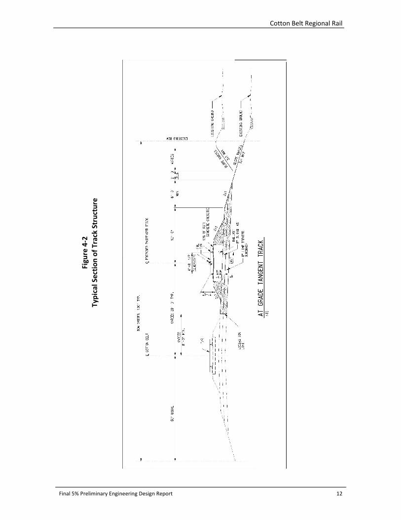
In the typical detail of track structure (see Figure 4-2) certain assumptions have been made to
develop order of magnitude costs for trackwork in the corridor. These assumptions will require
further review and refinements during subsequent design phases.
Cotton Belt Regional Rail
Final 5% Preliminary Engineering Design Report 12
Fig
ure
4-2
Ty
pic
al
Se
ctio
n o
f T
rack
Str
uct
ure

Cotton Belt Regional Rail
Final 5% Preliminary Engineering Design Report 13
Also, Direct Fixation Track is proposed in the Shallow Trench section of the alignment between
just west of Preston Road and west of Dickerson Street. A typical section detail of the proposed
Direct Fixation track is as shown below.
Fig
ure
4-3
Ty
pic
al
Se
ctio
n o
f D
ire
ct F
ixa
tio
n T
rack

Cotton Belt Regional Rail
Final 5% Preliminary Engineering Design Report 14
Special trackwork components will be required along the alignment for the movement of trains
from mainline to station passing track, from freight main to regional rail main, and also to
provide access to industrial sidings. For this purpose, turnout numbers 8, 10, 15 and 20 are
proposed to be used depending upon the speed requirements. Where necessary, double
crossovers and diamond crossings will also be considered. These special track units are expected
to use concrete ties and elastic fasteners.
Cotton Belt Vehicle Selection Criteria A major study component in the design development of the subject corridor is the
determination of an acceptable “Design Vehicle.” The vehicle selected should be a cost-
effective, efficient passenger rail vehicle sensitive to the needs and concerns of communities
located within the corridor. In order to initiate the design process of the corridor, the type of
vehicle must be evaluated and the “Design Vehicle” must be determined. The corridor design
will hinge on the selected vehicle and its ability to operate on the existing and proposed track.
The key elements in the design of the alignment are: curvature requirements; suitable gradient
to be considered for track profile design; vertical clearance requirements; acceleration,
deceleration and braking distance requirements; speed capabilities; wheel loads; and other
considerations to determine the vehicle.
A detailed study is required to determine which vehicle is most suited for operation on the
Cotton Belt Corridor. The study may consider the input from stakeholders and various agencies,
including the DART Board of Directors.
Freight Operations Local freight service is provided by short line and regional carriers. As passenger rail service is
developed in the corridor, consideration of local freight service is essential.
Four freight railroad companies operate within the corridor, through agreements, on DART-
owned tracks. Various agreements control the freight service activities within the Cotton Belt
Corridor. The Union Pacific Railroad has track usage rights on the entire corridor but operates no
trains. The corridor can be viewed as having three service areas with three freight service
providers. These freight service providers are: the Fort Worth and Western Railroad (FWWR) the
DGNO and the KCS.
Regional rail service and freight service operations would coexist within various Cotton Belt
Corridor segments. It is assumed one track would be dedicated for regional rail service and a
shared track would be maintained for both regional rail and freight service. However, some
sections may have a single track to minimize impacts if service can be accommodated within the
operating plan. Please see Appendix C, Existing Freight Operations Exhibit.
5.0 RIGHT-OF-WAY DART owns the Cotton Belt ROW. Property acquisitions will be required for proposed station
locations. Additional properties may be needed to expand some segments of the ROW to
achieve design speed, and to allow drainage, utility, structural and other guideway
improvements.
Cotton Belt Regional Rail
Final 5% Preliminary Engineering Design Report 15
6.0 UTILITY MODIFICATIONS Existing Utility Composite drawings have been prepared for the 5% submittal using record
drawings and Geographic Information Systems data obtained from the City of Coppell, City of
Grapevine, DFW Airport, Explorer Pipeline Company, Atmos Energy, Chesapeake Energy,
Verizon, Time Warner Cable, Oncor Electric, Sprint, Qwest Communications and other identified
utility owners. Another source of information used for the project regarding existing utilities is
DART documentation of utility license agreements. These agreements have been executed with
utility owners for the use of the Cotton Belt ROW for utility location and construction purposes.
The consultant team has coordinated with DART personnel and has received a list of known
license agreements associated with utilities that affect the project corridor.
One last source of information that has been used to document existing utilities in Section CB-1
of the project is the Subsurface Utility Engineering (SUE) investigation performed as part of
DART’s GEC-III Contract No. C-1013219. The limits of the SUE investigation extend from
downtown Fort Worth near NE 28th Street to IH 35E in the City of Carrollton. The SUE
investigation was documented on a set of drawings titled “Cotton Belt Composite Utilities, Mile
Post 603.50 to 632.27, Contract No. C-1013219” created by Gorrondona and Associates and
dated 12-27-2010. The SUE investigation includes up to Quality Level B utility location services
and determined approximate horizontal and vertical position of some of the underground
utilities within the corridor.
The completeness and accuracy of all information obtained regarding existing utilities have not
been fully verified. This information should be used for planning purposes only. The final
designer for the regional rail line system should verify and obtain accurate horizontal and
vertical information for existing utilities using subsurface utility engineering or other methods as
required to obtain appropriate information necessary for the design. Also, the contractor is
responsible for the verification of the location and elevation of all existing utilities affected by
the project prior to construction.
Utility and drainage modifications drawings have not been developed at the Final 5% Design
submittal. Due to limited scope of services after the May 18, 2011 Draft 5% design submittal,
the Existing Utility Composite Drawings were not updated with the most current rail alignments.
Therefore, the Utility Crossings lists contained in Appendix A reference the Guideway Plan and
Profiles drawings which contain the most current rail alignments as of the Final 5% design
submittal.
6.1 Section CB-1
A preliminary existing utility crossing list for Section CB-1 has been included in Appendix A of
this report. The most significant utility crossings and/or possible utility modifications that may
be required for the design and construction of the Cotton Belt Regional Rail in Section CB-1
include:
• Oncor 138 KV overhead (OH) electric transmission lines running longitudinally along the
southern half of the ROW between Stations 1163+81 and 1265+20
• An Explorer 12.75-inch petroleum line running longitudinally along the northern half of
the ROW from Station 1130+38 to the end of line section CB-1 and crossing the existing
tracks twice near Stations 1384+49 and 1385+20.
Cotton Belt Regional Rail
Final 5% Preliminary Engineering Design Report 16
• Sprint fiber optic and Qwest fiber optic lines running longitudinally along a meandering
path for the entire length of section CB-1
• 2 Chesapeake pipeline crossings, 12” gas line and 10” saltwater line, at approximately
Station 1025+00.
• Chesapeake gas valve station at approximately Station 1025+00.
The utilities listed above are discussed in more detail in the following paragraphs.
Existing Oncor 138 KV overhead electric transmission lines run longitudinally along Section CB-1
of the project between Stations 1163+81 and 1265+20 from Freeport Parkway to west of Moore
Road for approximately 1.92 miles. Oncor OH electric transmission high mast poles are located
on the south side of the existing freight rail line as well as the proposed regional rail line. The
horizontal clearance between Oncor OH electric transmission high mast poles and the proposed
regional rail line varies from approximately zero to 20 feet. Horizontal clearance requirements
must be evaluated for each of the 20 high mast poles associated with this OH electric
transmission line to determine how many of them must be relocated. At approximately Station
1217+80 the proposed rail crosses Denton Tap Road on an aerial structure. The vertical
clearance between the Oncor OH electric transmission lines must be evaluated to determine if
sufficient clearance exists at that location.
An existing Explorer 12.75-inch petroleum pipeline (approximately 19.5 miles long) is located
inside the Cotton Belt corridor generally parallel to the existing freight for most of the project
limits. This line extends from Royal Lane in the City of Coppell near the west end of the project
to US 75 in the City of Richardson near the east end of the project. The petroleum pipeline is
generally located approximately 32 feet north of the centerline of the existing freight tracks
throughout Section CB-1.
The proposed regional rail line in Section CB-1 is proposed to be located on the south side of the
existing freight line to avoid possible conflicts with or relocation of the Explorer petroleum
pipeline.
The Explorer petroleum pipeline crosses the proposed regional rail line twice in Section CB-1
near the intersection of Belt Line Road and Ledbetter Road near Stations 1384+49 and 1385+20,
respectively. Record drawings show that at both crossing locations the Explorer petroleum line
is inside an 18-inch O.D., 0.25 W.T. steel casing pipe.
Existing Qwest fiber optic and Sprint fiber optic lines run parallel to the corridor along a
meandering path for the entire length of Section CB-1. There are various locations where either
the Sprint or Qwest fiber optic line does not meet DART’s horizontal clearance requirements.
Between Stations 1010+00 to 1315+00 for approximately 5.8 miles, there are several locations
where the Qwest and Sprint fiber optic lines are located directly beneath or less than 15-feet
away from the centerline of the proposed regional rail line or proposed spur tracks realignment.
Horizontal clearance requirements need to be evaluated to decide the locations where these
fiber optic lines will be relocated.
The Qwest fiber optic line is less than 15-feet away from the centerline of the proposed regional
rail line between Stations 1029+00 and 1066+00 for approximately 3,700 feet, 1119+50 and
1131+00 for approximately 1,150 feet, 1172+00 and 1182+00 for approximately 1,000 feet,
Cotton Belt Regional Rail
Final 5% Preliminary Engineering Design Report 17
1204+00 and 1211+00 for approximately 700 feet, 1218+00 and 1219+00 for approximately 100
feet, 1242+00 and 1255+00 for approximately 1,300 feet and 1258+00 and 1314+00 for
approximately 5,600 feet.
The Sprint fiber optic line is less than 15 feet away from the centerline of the proposed regional
rail line between Stations 1104+50 and 1117+64 for approximately 1,314 feet, 1244+00 and
1269+00 for approximately 2,500 feet, 1278+00 and 1297+00 for approximately 1,900 feet, and
1385+30 and 1386+30 for approximately 100 feet.
Existing Chesapeake gas facilities impact the alignment at approximately Stations 1025+00. At
this location there are a 12” gas line and a 10” saltwater line that cross the alignment.
Additionally, a gas valve station exists at this location that directly conflicts with the proposed
rail alignment.
6.2 Section CB-2
A preliminary existing utility crossing list for Section CB-2 has been included in Appendix A of
this report. The most noteworthy utility crossings and/or possible utility modifications that may
be required for the design and construction of the Cotton Belt Regional Rail in Section CB-2
include:
• An Explorer 12.75-inch petroleum pipeline running longitudinally along the ROW
throughout Section 2 and crossing the existing and proposed rail lines at various
locations
• Qwest, Sprint and Verizon fiber optic lines running longitudinally along meandering
paths throughout the ROW for the entire length of Section CB-2
The utilities listed above are discussed in more detail in the following paragraphs.
The Explorer 12.75-inch petroleum pipeline exists longitudinally within the Cotton Belt Corridor
throughout all of Section CB-2. The pipeline crosses the proposed regional rail multiple times in
this section. It crosses once between the two branches of the Elm Fork Trinity River near Station
2018+00, once just west of IH 35E near Station 2092+00, several times across the various tracks
in the Downtown Carrollton Mercer Yard area, twice just west of Kelly Boulevard near Stations
2200+50 and 2204+75, once west of Surveyor Boulevard near Station 2304+50 and once east of
Surveyor Boulevard near Station 2314+25.
It is anticipated that the Explorer petroleum pipeline will require relocation in areas where the
existing utility is located closer than 20 feet to the proposed regional rail line or associated
proposed tracks. There are several segments of the petroleum line that fall within this 20 feet
minimum recommended separation distance. Those segments include the area near IH 35E and
Broadway Street between Stations 2097+00 and 2109+00, the portion of the line near the east
end of the Mercer Yard between Stations 2121+00 and 2134+00, and 85% of the length of the
petroleum line between Josey Lane and Spectrum Drive between Stations 2175+00 and
2379+50.
Quest, Sprint and Verizon fiber optic lines exist longitudinally within the Cotton Belt Corridor
throughout Section CB-2. These lines cross the track at various locations but are predominantly
longitudinal with the track. Significant portions of the Sprint lines will require relocation
Cotton Belt Regional Rail
Final 5% Preliminary Engineering Design Report 18
between Stations 2094+50 to 2106+00, 2123+00 to 2125+50, 2132+50 to 2137+50, and 2152+50
to the end at 3010+00. Additionally, Sprint fiber optic lines are mounted on the existing bridge
structures between Stations 2010+50 to 2013+20, 2036+11 to 2040+29 and 2077+34 to
2079+14. A majority of the Quest and Verizon fiber optic lines are outside the minimum
recommended 15 feet separation distance and can remain in place, except in the area along
Cecil Drive.
6.3 Section CB-3
A preliminary existing utility crossing list for Section CB-3 has been included in Appendix A of
this report. There are several noteworthy utility crossings and/or possible utility modifications
that may be required for the design and construction of the Cotton Belt Regional Rail in Section
CB-3 include:
• An Explorer 12.75-inch petroleum pipeline running longitudinally along the ROW
throughout most of Section CB-3 and crossing the existing and proposed rail lines at
various locations
• Qwest, Sprint and Verizon fiber optic lines running longitudinally along meandering
paths throughout the ROW for the entire length of Section CB-3
• Most utilities located in the area of the proposed Shallow Trench beginning west of
Preston Road and ending near Coit Road between Stations 3065+00 and 3216+00
The utilities listed above are discussed in more detail in the following paragraphs.
The Explorer 12.75-inch petroleum pipeline exists longitudinally within the Cotton Belt Corridor
throughout most of Section CB-3 from the DNT to US 75. The pipeline crosses the proposed
regional rail three times in this section. It crosses once just east of the KCS railroad near Station
3284+00, once east of West Renner Road near Station 3307+00 and once east of Alma Road
near Station 3381+50 at which point it exits the rail ROW and does not return again within the
limits of the eastern end of this project.
Again, it is anticipated that the Explorer petroleum pipeline will need to be relocated in areas
where the existing utility is located closer than 20 feet to the proposed regional rail line or
associated proposed tracks. There are several segments of the petroleum line that fall within the
20 feet minimum recommended separation distance in Section CB-3 of the project. Those
segments include an area near White Rock Creek between Stations 3036+00 and 3042+00, an
area between Chalfont Court and east of Preston Road between Stations 3052+00 and 3087+00,
and most of the line from Waterview Parkway to east of Synergy Park Boulevard between
Stations 3261+00 and 3298+00 and between Stations 3288+50 and 3298+00.
Quest, Sprint and Verizon fiber optic lines exist longitudinally within the Cotton Belt Corridor
throughout most of Section CB-3. These lines cross the track at various locations but are
predominantly longitudinal with the track. Significant portions of the Sprint lines will require
relocation. A majority of the Quest and Verizon fiber optic lines are outside the minimum
recommended 15 feet separation distance and can remain in place.
The Sprint fiber optic line is less than 15 feet from the proposed alignment from Stations
3010+00 to 2014+00, 3020+00 to 3049+00, 3053+00 to 301+00, 3148+50 to 3160+00, 3260+00
to 3283+00, and 3314+50 to 339+50. With the new alignment of the freight line, the Sprint fiber
Cotton Belt Regional Rail
Final 5% Preliminary Engineering Design Report 19
optic line is less than 15 feet from the proposed freight alignment from Station 13+00 to
152+50.
The Qwest fiber optic line is less than 15 feet from the proposed alignment from Stations
3034+00 to 3037+00, 2108+00 to 3110+50, 3192+50 to 3201+00, 3239+50 to 3262+50, 3288+50
to 3294+50, 3311+00 to 3351+00, 3378+00 to 3392+50, 3397+00 to 3399+00, 3402+50 to
3404+00, and 3420+00 to 3442+00.
The Verizon fiber optic line is less than 15 feet from the proposed alignment from Stations
3381+00 and 3391+00.
The Oncor overhead electric line is less than 15 feet from the proposed alignment between
Stations 3020+00 to 3043+00 and 3063+00 to 3071+50. The Oncor underground electric line is
less than 15 feet from the proposed alignment from Station 3357+50 to 3377+50.
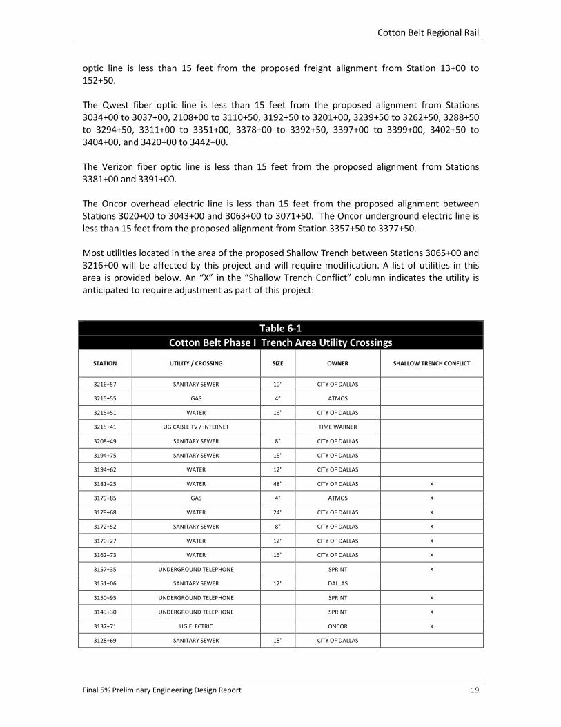
Most utilities located in the area of the proposed Shallow Trench between Stations 3065+00 and
3216+00 will be affected by this project and will require modification. A list of utilities in this
area is provided below. An “X” in the “Shallow Trench Conflict” column indicates the utility is
anticipated to require adjustment as part of this project:
Table 6-1
Cotton Belt Phase I Trench Area Utility Crossings
STATION UTILITY / CROSSING SIZE OWNER SHALLOW TRENCH CONFLICT
3216+57 SANITARY SEWER 10" CITY OF DALLAS
3215+55 GAS 4" ATMOS
3215+51 WATER 16" CITY OF DALLAS
3215+41 UG CABLE TV / INTERNET TIME WARNER
3208+49 SANITARY SEWER 8" CITY OF DALLAS
3194+75 SANITARY SEWER 15" CITY OF DALLAS
3194+62 WATER 12" CITY OF DALLAS
3181+25 WATER 48" CITY OF DALLAS X
3179+85 GAS 4" ATMOS X
3179+68 WATER 24" CITY OF DALLAS X
3172+52 SANITARY SEWER 8" CITY OF DALLAS X
3170+27 WATER 12" CITY OF DALLAS X
3162+73 WATER 16" CITY OF DALLAS X
3157+35 UNDERGROUND TELEPHONE SPRINT X
3151+06 SANITARY SEWER 12" DALLAS
3150+95 UNDERGROUND TELEPHONE SPRINT X
3149+30 UNDERGROUND TELEPHONE SPRINT X
3137+71 UG ELECTRIC ONCOR X
3128+69 SANITARY SEWER 18" CITY OF DALLAS

Cotton Belt Regional Rail
Final 5% Preliminary Engineering Design Report 20
Table 6-1
Cotton Belt Phase I Trench Area Utility Crossings
3126+95 GAS 3" ATMOS X
3126+80 WATER 12" CITY OF DALLAS X
3126+13 UNDERGROUND TELEPHONE VERIZON X
3110+86 WATER 16" CITY OF DALLAS
3110+80 GAS 4" ATMOS X
3102+42 SANITARY SEWER 21" CITY OF DALLAS
3098+72 GAS 6" ATMOS
3098+55 WATER 8" CITY OF DALLAS
3098+37 UG ELECTRIC ONCOR
3098+06 UG ELECTRIC ONCOR
3087+55 SANITARY SEWER 8" CITY OF DALLAS
3086+86.68 UG TELEPHONE SPRINT X
3070+00 to
3086+00 PETROLEUM LINE 12.75" EXPLORER X
3081+12 GAS 12" ATMOS X
3076+02 WATER 24" CITY OF DALLAS X
3072+20 WATER 12" CITY OF DALLAS X
3072+93 GAS 6" ATMOS X
In addition to the previously described utilities, there are hundreds of other existing utility lines
that cross the Cotton Belt. Since the corridor currently includes or has previously included an
active freight rail line along most portions of the proposed alignment, most of the existing
underground utilities have already been installed in accordance with typical railroad crossing
criteria. This means that most existing utilities have an acceptable level of ground cover above
the utility line and below the existing rail elevation. Also, most existing utilities have been
installed inside an encasement pipe underneath the existing tracks and outside the area of the
existing tracks for a certain horizontal distance.
Although our utility research has verified this is the case in most circumstances, this project will
still require adjustments to many existing utilities in many areas of the project. This is true
because many existing utilities were not encased from ROW line to ROW line across the entire
railroad corridor. Instead, they may have been encased for only a distance of 50 or 75 feet
centered on the existing track. In this situation, the encasement pipe would have to be
lengthened in areas where this project is proposing a new rail line parallel to the existing one.
Also, existing utility lines may have been constructed with adequate ground cover below the
existing rail, but may no longer have sufficient cover in areas where this project is proposing
new parallel rail lines at different elevations.
Finally, there are numerous at grade utilities, predominantly at street crossings, that conflict
with the new alignment and will need to be relocated. Most of these utilities fall into the
following categories: light posts, traffic signal posts, crossing gates, railroad control utilities and
in rare instances water and sanitary sewer manholes.
Cotton Belt Regional Rail
Final 5% Preliminary Engineering Design Report 21
Early coordination with the utility owners will be critical to planning for the modification of
utilities as part of this project. Power, water facilities and petroleum lines cannot be taken out of
service without regard to the time of year and the demand for service. Normally, large water
mains and electric power facilities can be shut down during the winter months when demand
for water and electricity is at its lowest. Coordination with gas and petroleum line owners is
equally important. Early coordination with the utility owners will be crucial to keeping the
project on schedule.
Potholing and additional SUE efforts are recommended during the final design effort and prior
to the commencement of construction activities in order to locate existing utilities more
accurately and to verify existing cover and pipe encasement characteristics. All utility crossings
will need to be reviewed for compliance with DART’s utility crossing requirements. Water and
sanitary sewer mains will need to be encased. Utilities that cross on a diagonal will need to be
realigned to cross the tracks perpendicularly where possible. Acceptable amounts of cover over
crossing utility lines must be provided.
7.0 BRIDGE AND STRUCTURAL DESIGN
7.1 Bridge Design
All the bridges along the Cotton Belt Corridor were designed in accordance with the latest
version of AREMA Manual for Railway Engineering (to be called “AREMA Manual” hereafter).
The existing Cotton Belt Corridor single track is an active freight train corridor, with the
exception of the north Dallas segment where the freight train operations have been abandoned.
The proposed Cotton Belt Corridor Regional Rail Line will be a double-track corridor for the
mixed traffic (freight train and passenger train). The existing Cotton Belt Corridor single track
will be rebuilt to be one of the two proposed tracks, while the other new track will be built
parallel to the existing track.
All structures/bridges were designed in accordance with the AREMA Manual and DART Design
Criteria with the train loads defined as follows.
• Train loading of Cooper E-80 as specified in the AREMA Manual for most of the
proposed bridges which may be shared with freight operations and are located over the
portion of the alignment where the current track is still active for the freight train
operation. These bridges are located in Section 1 – CB1 and Section 2 – CB2.
• AREMA Cooper E-40 train loading for all bridges, which are located over the portion of
the alignment where the existing track is not currently used for freight train operations.
These bridges include all the proposed new bridges located in Section 3 – CB3.
• AREMA Cooper E-40 train loading for the bridges, which are proposed for the passenger
rail operations only. These bridges include those bridges located in Section 1 – CB1 as
DFW International Airport Access Bridge, the grade separation bridge at S. Denton Tap
Road, and the bridges located in Section 2 - CB2 as Downtown Carrollton Rail Station
overpass bridge and the Midway grade separation bridge.

Cotton Belt Regional Rail
Final 5% Preliminary Engineering Design Report 22
7.2 Section 1 - CB1
All the existing bridges along the current single-track corridor are either river-crossing or creek-
crossing bridges or roadway overpasses. The existing bridge typically has open deck track, which
is supported on steel beam or even wooden beams. The existing bridge beams are mainly
supported on steel pile piers or wooden trestle piers. All the existing bridges have a maximum
span length of 30 feet or the existing piers are located no more than 30 feet apart. Each existing
bridge has multiple piers located inside the river or creek channels.
The field inspection of the existing bridges indicates the existing bridges are very old and appear
to be in unsound structural condition or not in compliance with the current AREMA Manual
requirements for freight operations. Therefore, most existing bridges are to be replaced with
new bridges.
There are a total of eight bridges proposed for Section 1. The approximate locations and main
features of these bridges are listed below:
• Cottonwood Branch crossing, west of SH 121, 80 feet long from Stations 1051+34 to
1052+14, direct-fixation dual-track, steel through girder bridge. Design loads: AREMA
Cooper E80.
• Unnamed channel crossing, west of SH 121, 65 feet long from Stations 1060+11 to
1060+76, direct-fixation dual-track, steel through girder bridge. Design loads: AREMA
Cooper E80.
• Grapevine Creek Crossing I, west of S. Denton Tap Road, 140 feet long from Stations
1198+25 to 1199+65, ballasted dual-track, prestressed concrete box beam bridge.
Design Loads: AREMA Cooper E40.
• S. Denton Tap Road, 476 feet long from Stations 1216+29 to 1221+05, single-track, two-
span of steel plate girder bridge over the roadway and five spans of prestressed
concrete I-beam bridge. Design Loads: AREMA Cooper E40.
• S. Denton Tap Road for Cypress Waters Option, 295 feet long from Station 1217+15 to
1220+20, ballasted dual-track, three spans of steel plate girder bridge over the roadway.
Design Loads: AREMA Cooper E40
• Grapevine Creek Crossing II, west of Mockingbird Lane, 132 feet long from Station
1294+47 to 1295+79, direct-fixation dual-track, steel through girder bridge. Design
loads: AREMA Cooper E80.
• Trinity River Elm Fork west channel crossing, east of Fairway Drive, 1,020 feet long from
Stations 1362+40 to 1372+60, ballasted dual-track, prestressed concrete box beam
bridge. Design Loads: AREMA Cooper E80.
An existing timber bridge roughly 70 fee long from approximately Station 1220+30 to 1221+00
will remain. An existing timber bridge roughly 910 feet long from approximately Station
1336+26 to 1345+36 will be demolished and will be replaced by embankment.
The Cotton Belt Corridor access to DFW Airport will share a bridge over SH 114 with the T’s Fort
Worth TEX Rail commuter rail. The design and construction of the bridge will be done by the
Fort Worth T.
The superstructures of the new bridges over the creeks or river channels are designed to have a
minimum one foot freeboard above the 100-year flood elevation. The low chord of the
Cotton Belt Regional Rail
Final 5% Preliminary Engineering Design Report 23
superstructure has a minimum clearance of 16-feet 6-inches over the roadway for the S. Denton
Tap Road grade separation bridge.
The overall length and span lengths of each new bridge are designed to be the same or longer
than the existing bridge at the same river or creek location in order to maintain the current
discharge capacity of the river or creek.
Each of the dual-track concrete beam bridges will have an identical and separate new bridge
superstructure while the single united substructure will be supporting two bridge
superstructures. The dual-track bridges will be built in two phases as described below:
• Build the bridge for the proposed new track first while maintaining the operation of the
existing bridge during the construction
• Shift the train operation to the new bridge after its construction is completed
• Replace the existing bridge with a new bridge as outlined above
7.3 Section 2 - CB2
All the existing bridges along the current single track corridor are either river or creek crossings,
except for one existing bridge over an unnamed dirt road. The existing bridge typically has open
deck track, which is supported on steel beams, concrete box beams or even wooden beams.
The existing bridge beams are mainly supported on steel pile piers or wooden trestle piers. All
the existing piers are located at no more than 30 feet apart or all the existing bridges have a
maximum span length of 30 feet. Each existing bridge has multiple piers located inside the river
and creek channels or over the unnamed dirt road.
The field inspection of the existing bridges indicates that they are very old and appear to be in
unsound structural condition or not in compliance with the current AREMA Manual
requirements. Therefore, the existing bridges are to be replaced with new bridges.
There is a new passenger-rail-only bridge proposed to cross over the existing BNSF line in
downtown Carrollton, span over a small creek just east of downtown and then cross over
Midway Road. Each of the three bridges carries one track, which is parallel to the adjacent at-
grade existing corridor track.
Seven bridges are proposed for Section 2. The approximate locations and main features of
these bridges are listed below:
• Elm Fork Branch of the Trinity River main channel crossing, 265 feet long from Station
2010+55 to 2013+20, ballasted dual-track, prestressed concrete box beam bridge.
Design loads: AREMA Cooper E80.
• Elm Fork Branch of the Trinity River East channel crossing, 418 feet long from Station
2036+11 to 2040+29, ballasted dual-track, prestressed concrete box beam bridge.
Design loads: AREMA Cooper E80.
• Unnamed minor road crossing, 35 feet long from Station 2057+97 to 2058+32, ballasted
dual-track, prestressed concrete box beam bridge. Design loads: AREMA Cooper E80.
• Hutton Branch of the Trinity River crossing, west of IH 35E, 180 feet long from Station
2077+34 to 2079+14, ballasted dual-track, prestressed concrete box beam bridge.
Design loads: AREMA Cooper E80.

Cotton Belt Regional Rail
Final 5% Preliminary Engineering Design Report 24
• BNSF flyover bridge at downtown Carrollton, 880 feet long from Station 2119+68 to
2128+48, ballasted single-track (Southbound), prestressed concrete box beam bridge.
Design loads: AREMA Cooper E40.
• Unnamed stream crossing at downtown Carrollton, 75 feet long from Station 2132+77
to 2133+52, ballasted single-track (Southbound), prestressed concrete box beam bridge.
Design loads: AREMA Cooper E40.
• Midway Road grade separation bridge, 600 feet long from Stations 2330+92 to 2336+92,
ballasted single-track (Southbound), two steel plate girder spans over Midway Road and
prestressed concrete box beam spans on either end of the steel spans. Design loads:
AREMA Cooper E40.
The bridges over the creek, river channel or dirt road as listed above will be built in the manner
similar to that for those bridges over the creek as proposed for the corridor alignment Section 1.
The dual-track bridge will have the separate bridge superstructure and shared substructure.
The low chords of the new bridge superstructures over each creek or river crossing are designed
to have a minimum one foot freeboard above the 100-year flood elevation. The low chord of
the superstructure has a clearance of about 14 feet, 0 inches over the unnamed minor road
while the adequate clearance as required will be provided for the bridges over the existing BNSF
track and/or highways.
Prestressed concrete box beams, prestressed concrete I beams, or steel plate girders are utilized
for all the bridges along Section 2 – CB2.
7.4 Section 3 - CB3
All the existing bridges along the current single track corridor are river crossings, creek-crossings
or roadway grade separation bridges. The existing bridge typically has an open deck track or
closed deck. The bridge decks are supported on steel beam, concrete beam, concrete box
beam, wooden beam, steel truss or steel through girder. The existing bridge beams are mainly
supported on steel pile piers, concrete piers or wooden trestle piers.
The field inspection of the existing bridges indicates that:
• Some of the existing bridges appear to be in good condition and they are tentatively
considered to be preserved to support one track of the corridor. These existing bridges
are located at North Dallas Tollway, Synergy Park Boulevard, W. Renner Road, Spring
Creek and US 75.
• All other existing bridges are very old and appear to be in unsound structural condition
or not in compliance with the current AREMA Manual requirements. Therefore, all these
unsound existing bridges are to be replaced with new bridges.
New grade separation bridges are proposed to cross over Coit Road, US 75 and Plano Parkway.
There is a new bridge proposed for crossing over US 75 at different locations for the North
Option and South Option as well, while the new bridge proposed to cross Plano Parkway is for
the South Option only.
The approximate locations and main features of the bridges for Section 3 are listed below:
Cotton Belt Regional Rail
Final 5% Preliminary Engineering Design Report 25
• North Dallas Tollway, 124 feet long from Station 3010+53 to 3011+77, direct-fixation
single track (Northbound), steel plate girder bridge. Design loads: AREMA Cooper E40.
• White Rock Creek Crossing, 140 feet long from Station 3046+19 to 3047+59, ballasted
dual-track, steel plate girder bridge. Design loads: AREMA Cooper E40.
• McKamy Branch Creek Crossing, 180 feet long from Station 3101+55 to 3103+35, direct-
fixation dual-track, steel through girder bridge. Design loads: AREMA Cooper E40.
• Osage Branch Crossing 1, 140 feet long from Station 3128+22 to 3129+62, direct-fixation
dual-track steel through girder bridge. Design loads: AREMA Cooper E40.
• Osage Branch Crossing 2, 50 feet long from Station 3149+79 to 3150+29, direct-fixation
dual-track, steel through girder bridge. Design loads: AREMA Cooper E40.
• Coit Rd. Roadway Bridge, 180 feet long, 90 feet wide at approximate Station 3216+00.
Design loads: ASHTO HL-93.
• Synergy Park Boulevard, 194 feet long from Station 3292+88 to 3294+82, direct-fixation
single track, ASHHTO Type IV girder bridge. Design loads: AREMA Cooper E40.
• W. Renner Road, 581 feet long from Station 3299+68 to 3305+49, ballasted single track
(Northbound), multi-span prestressed concrete beam bridge. Design loads: AREMA
Cooper E40.
• Spring Creek Bridge for the North Option, 320 feet long from Station 3387+88 to
3391+08, ballasted single track (Northbound), multi-span, prestressed concrete beam
bridge. Design loads: AREMA Cooper E40.
• US 75 Bridge for the North Option, 1,212 feet long from Stations 3404+85 to 3416+97,
ballasted single track (Northbound), four steel plate girder spans over the US 75 main
roadway and service roadways in addition to multi-spans of prestressed concrete beams
on each end of the steel span. Design loads: AREMA Cooper E40.
• US 75 Bridge for the South Option, 3,050 feet long from Stations 3388+27 to 3418+17,
ballasted dual-track, steel plate girder span connected to multi-span prestressed
concrete beams on each end of the steel span. Design loads: AREMA Cooper E40.
• Plano Parkway Bridge for the South Option, 480 feet long from Stations 3447+37 to
3452+17, direct fixation dual-track steel plate girder and ballasted concrete girder span
bridge. Design loads: AREMA Cooper E40.
• 12th
Street Aerial Station Bridge, 955 feet long from Station 3497+00 to 3488+55,
ballasted dual-track, typical concrete girder spans and two steel plate girder spans
crossing Avenue K and Municipal Avenue. Design loads: AREMA Cooper E40.
The approximate length, width and location of roadway bridges for Shallow Trench option are
list below.
• Davenport Rd. W Bridge, 340 feet long, 90 feet wide at Station 3098+00. Design loads:
AASHTO HL-93.
• Campbell Rd. Bridge, 458 feet long, 90 feet wide at Station 3110+00. Design loads:
AASHTO HL-93.
• Davenport Rd. E Bridge, 390 feet long, 50 feet wide at Station 3127+00. Design loads:
AASHTO HL-93.
• Hillcrest Rd. Bridge, 132 feet long, 90 feet wide at Station 3163+00. Design loads:
AASHTO HL-93.
• McCallum Blvd. Bridge, 132 feet long, 65 feet wide at Station 3171+00. Design loads:
AASHTO HL-93.

Cotton Belt Regional Rail
Final 5% Preliminary Engineering Design Report 26
• Meandering Way Bridge, 132 feet long, 50 feet wide at Station 3179+00. Design loads:
AASHTO HL-93.
• Coit Rd. Bridge, 180 feet long, 90 feet wide at Station 3216+00. Design loads: AASHTO
HL-93.
The low chords of the new bridge superstructures crossing each river or creek are designed to
have a minimum one foot freeboard above the pre-project or post-project 100-year flood
elevation. The low chord of the superstructure has a minimum clearance of 16 feet, 6 inches
over all the traffic roadways.
Each bridge superstructure is designed based on the bridge site features and condition. As a
result, the steel through girder, the prestressed concrete beam, steel plate girder or a
combination of two span types are utilized for those proposed bridges.
The bridges over the floodplains will be designed with single spans, where possible, without
piers in the creeks or as multi-span bridges with a minimum number of piers to minimize
impacts on the floodplains.
The concrete drilled shaft foundations are used for all the proposed bridges along all three
sections (CB1, CB2 and CB3).
See Appendix D, Bridge Structures List table for a summary of bridge information for the project.
8.0 DRAINAGE Drainage features have been added to the Existing Utility Composite Drawings prepared for the
5% submittal. Items were identified using record drawings obtained from the Cities of Grapevine
and Coppell, the Town of Addison and the Cities of Carrollton, Dallas, Richardson and Plano. Due
to access restrictions, limited field observations were made prior to this submittal to verify
locations and sizes of existing drainage structures. The final designer should verify and obtain
accurate horizontal and vertical information for all existing drainage structures using on-the-
ground survey and field investigations.
Drainage area maps for the Cotton Belt 5% submittal were prepared using a combination of
existing drainage area maps provided by the local municipalities listed above and aerial
topography provided by DART. Drainage areas have been verified using NCTCOG’s aerial
topography for areas outside the DART topographic limits. Due to the limitations in the scope of
work for the preliminary engineering, only off-site drainage areas were identified. Local wall
drain and track drainage areas will be determined during final design.
Drainage discharges have been calculated for a 100-year storm event to provide adequate
drainage facilities in accordance with DART design criteria and the design criteria for the
appropriate city. Times of concentration were calculated for each sub-area using formulas from
the DART Design Manual. Discharges for drainage areas smaller than 200 acres were determined
using the Rational Method. For major creek crossings hydrologic information was taken from the
existing study or hydraulic and hydrologic models.
Cotton Belt Regional Rail
Final 5% Preliminary Engineering Design Report 27
Although no utility modification sheets are included in the 5% plans, drainage modifications will
be required as a part of this project. Drainage facilities that cross under the existing Cotton Belt
rail are included in the Existing Utility Matrix provided as Appendix A.
Existing drainage structures on the proposed alignment shall be examined and analyzed to
determine whether or not a full replacement or additional culverts and/or extensions are
necessary to convey design flows. Additionally, the structural integrity of the existing drainage
crossings must be evaluated with respect to design loadings prior to any final decision on their
suitability for use in the final design. Storm sewers and culverts shall be provided for increased
runoff due to any drainage sub-areas created by the work performed to construct the line. New
drainage structures at track crossings will meet current storm drainage design requirements.
These proposed storm sewers will be connected to existing systems, which will not be improved
beyond the DART ROW or limits of construction unless determined otherwise by the final
section designer.
8.1 Section CB-1
8.1.1 Overview Generally, Cotton Belt Line Segment 1 crosses sub-basins contributing to Grapevine and
Cottonwood creeks. Most of the Cotton Belt Line Segment 1 neither changes drainage areas nor
alters overall runoff characteristics of major basins crossing the proposed alignment. Minor
changes to the existing drainage, flow paths and runoff characteristics should be expected along
and adjacent to the DART ROW. Construction of Cotton Belt Line Segment 1 will have limited
impact on existing drainage patterns.
This submittal demonstrates intermediate designs utilizing combinations of open channels or
ditches with culvert crossings and includes storm sewer relocations. Complete underdrain
systems design was not included as part of this preliminary design; however, it will be the
responsibility of the final section designer. Open channel ditches located within the DART ROW
will be utilized to carry 100-year storm runoff. Areas along the alignment where the permanent
railroad ROW is limited will require additional drainage easements for constructing planned
drainage ditches or storm structures as incurred from this design. Ditches will generally have a
depth of two feet and a minimum bottom width of two feet, with maximum 3:1 fore slopes and
4:1 back slopes. In areas along the alignment where it is required to reduce the DART easement
width or additional drainage easement widths due to constraints by manmade or natural
features, low height reinforced concrete flumes may be used pending the condition that design
capacity can be achieved. Proposed ditches will generally have the same profile as the vertical
alignment grade of the track, with some exceptions of the proposed ditches connecting to
existing ditches or structures, or the need to create an artificial high point that causes grades to
flow against the grade of the track. All cross-sections and Utility Modification Composite final
design sheets will reflect the horizontal and vertical location of drainage ditches.
In areas along the alignment where planned drainage ditches intercept storm runoff from large
drainage areas, underground storm systems and inlets may be required in addition to open
channels and flumes to convey storm runoff to existing creeks and tributaries. These
underground storm systems will be designed by the final section designer.
Cotton Belt Regional Rail
Final 5% Preliminary Engineering Design Report 28
8.1.2 Areas of Importance During final design, the hydraulic capacity of existing creek and tributary crossings will be
calculated and compared to the expected storm runoff. Hydraulic studies shall be performed for
creek crossings at Stations 1051+35 and 1060+17 on Cottonwood Creek and at Stations 1198+34
and 1294+44 on Grapevine Creek using HEC-RAS modeling to determine 100-year water surface
elevations, and cross-sections shall be developed to determine the water surface limits. The
vertical alignment of the track at these crossings will be determined using DART design criteria
with respect to the 100-year water surface elevations and limits. Limited or no modifications
shall be planned for creeks beneath proposed aerial rail crossings with the exception of slope
stabilization that may be required as determined by the final section designer.
The existing aerial crossing of a drainage channel at Station 1220+68 shall be replaced with a
proposed culvert rail crossing. All existing inline culverts shall be utilized for ditches crossing
existing roads, private driveways and similar utilities. A summary of existing culvert structures
and crossings is listed in Appendix A. Replaced and/or relocated storm sewers and inlets
including but not limited to systems concentrating along the proposed rail will be connected to
existing systems and shall be reflected in the Utility Modification Composite sheets.
8.2 Section CB-2
8.2.1 Overview The Cotton Belt Line Section CB-2 neither changes drainage areas nor alters the overall runoff
characteristics of major basins crossing the proposed alignment. Open ditches run along both
sides of the existing rail. Where possible, the existing ditch will be shifted to accommodate the
proposed rail. Where this is not possible due to ROW constraints or other conflicts, an enclosed
storm drain system will be proposed. Proposed ditches will generally have the same profile as
the existing ditches in order to minimize off-site impacts. The hydraulic capacity of major ditches
will be evaluated to ensure adequate freeboard. Smaller ditches will be designed by the final
section designer.
8.2.2 Areas of Importance The areas of importance for the CB-2 line section are related to the two creek crossings.
Portions of the downtown Carrollton area are in the 100-year floodplain of Hutton Branch.
Where the proposed alignment is at-grade it is important to ensure there is adequate freeboard
above the 100-year water surface elevation.
Both Addison and Carrollton are largely developed along the corridor. In both communities
there are several spur tracks that provide freight access into nearby warehouses. Special
attention will be given to the drainage across the spur tracks to ensure that existing drainage
patterns are maintained and that freight rail design criteria are met. Additionally, there are
several cross culverts that will potentially need to be replaced in order to accommodate the
proposed alignment.
8.2.3 Hydraulics Line Section CB-2 crosses two major water courses; the Elm Fork of the Trinity River and Hutton
Branch. Both of these waterways have been studied and have floodplains mapped by the
Federal Emergency Management Association (FEMA). Additionally, the Elm Fork is identified as
Cotton Belt Regional Rail
Final 5% Preliminary Engineering Design Report 29
being in the Regulatory Zone of the Trinity River Corridor, as designated in the Trinity River
Corridor map. The following summarizes the waterway crossing for CB-2. A more detailed
discussion of the hydraulic modeling, design requirements and permitting requirements will be
provided at the 10% level in a separate Hydraulic Report.
Elm Fork Trinity River The Cotton Belt alignment crosses the Elm Fork of the Trinity River in Carrollton 120 feet
upstream of Belt Line Road. The latest HEC-RAS model (modified August 2010) was obtained
from the U.S. Army Corps of Engineers (USACE) and utilizes HEC-RAS Version 4.1.0.
There are three bridge crossings of the Elm Fork – one bridge over the main channel and one
each in the left and right overbanks. The existing main channel structure is modeled as 237 feet
long with two 8-foot diameter piers and a section depth of four feet. The existing structure over
the left overbank is modeled as 392 feet with seven 10-foot diameter piers and a section depth
of 2.8 feet. The existing structure over the right overbank is modeled as 1,013 feet with eight 17-
foot diameter piers and a section depth of 2.8 feet. The 100-year water surface elevation is
441.58 at Section 87541. The Elm Fork floodplain influences the proposed Cotton Belt regional
rail from CB-1 Station 1360+00 to CB-2 Station 2053+00.
Any changes or improvements within the Elm Fork floodplain must comply with FEMA
regulations and with the requirements associated with obtaining a Corridor Development
Certificate (CDC), as well as any local floodplain requirements. The requirements having the
most impact on this project are: no rise in 100-year water surface elevation (within four-
hundredths of a foot), no significant increase in the Standard Project Floor (SPF) water surface
elevation and 0% and 5% maximum allowable valley storage loss for the 100-year and SPF
events respectively.
A modified conditions HEC-RAS model was developed to include areas of ineffective flow in the
downstream and upstream cross-sections of the existing right overbank bridge that were not
included in the existing model. This was done in agreement with the USACE and verified with a
map they provided, which shows the ineffective flow delineation. An additional cross section
upstream of the bridge (87551) at DART’s ROW limit was added to this model as well.
The modified model was used to develop a preliminary proposed conditions model to show the
impacts of the proposed Cotton Belt alignment on the Elm Fork. In the proposed conditions, all
three bridges have been modeled with 4-foot piers spaced approximately every 50 feet and a
40-foot deck width. The results indicate that excavation upstream might be required to prevent
increases in water surface elevation for the 100-year storm event. Also, a minimum low chord
elevation of 447.7 feet might be required in order to prevent significant increases in the SPF
water surface elevation.
Hutton Branch Hutton Branch influences the Cotton Belt Regional Rail alignment in two places. The first is at
the creek crossing west of IH 35E, at rail Station 2078+00. The second area is in Downtown
Carrollton, where the alignment parallels Hutton Branch.
The Cotton Belt crosses Hutton Branch midway between Luna Road and IH 35E. The HEC-RAS
model used in the FEMA map modernization effort was obtained from the City of Carrollton. The

Cotton Belt Regional Rail
Final 5% Preliminary Engineering Design Report 30
model utilizes HEC-RAS V3.1.3 and fully developed discharges. The existing bridge is modeled as
13 spans supported by 24-inch diameter piers for a total length of 179 feet, with a section depth
of 1.8 feet. The 100-year water surface elevation is 443.32.
In the Downtown Carrollton area, the rail alignment is parallel to Hutton Branch and crosses
through a portion of the Hutton Branch floodplain. Any fill placed within the effective flow area
of Hutton Branch will impact the 100-year water surface elevations and velocities. Additionally,
any fill placed within the floodplain of Hutton Branch must be mitigated to ensure that there is
no loss of valley storage. The alignment crosses an unnamed tributary to Hutton Branch at Rail
Station 2133+00. A new HEC-RAS model of the tributary was created to determine if the
proposed improvements impact the 100-year water surface elevation. Results showed that the
100-year flow is contained to the channel and there are no impacts to the unnamed tributary.
8.3 Section CB-3
8.3.1 Overview The Cotton Belt Line Section CB-3 neither changes drainage areas nor alters the overall runoff
characteristics of major basins crossing the proposed alignment. Open ditches run along both
sides of the existing rail. Where possible, the existing ditch will be shifted to accommodate the
proposed rail. Where this is not possible due to ROW constraints or other conflicts, an enclosed
storm drain system will be proposed. Proposed ditches will generally have the same profile as
the existing ditches in order to minimize off-site impacts. The hydraulic capacity of major ditches
will be evaluated to ensure adequate freeboard. Smaller ditches will be designed by the final
section designer.
8.3.2 Areas of Importance There are several areas of importance in Line Section CB-3. The first is in the North Dallas area
between the DNT and Coit Road. There are a couple of alignment alternatives in this area, and
all of them require consideration of the flood elevation of nearby creeks. The alignment crosses
three creeks, and the floodplain runs along the rail for several thousand feet. The creek
hydraulics are discussed in Section 8.3.3. A large amount of storm runoff crosses under the rail
east of Knoll Trail Drive. Before development occurred, this stream was the Addison Branch of
White Rock Creek. In order to meet freeboard requirements, the existing culverts need to be
replaced to provide additional capacity. The hydrology at this crossing will be examined for the
10% submittal to ensure there are no negative impacts downstream of the crossing. There are a
number of smaller cross culverts in the area that must be adjusted to accommodate the
proposed alignment at the following rail stations: Station 3086+81, Station 3095+44, Station
3121+50, Station 3193+00 and Station 3208+00. Additionally, shallow ditches or flumes will
intercept runoff before it gets to the proposed retaining walls. These will follow the existing
ground alignment and outfall at a creek or cross culvert.
8.3.3 Hydraulics
White Rock Creek Line Section 3 of the Cotton Belt crosses White Rock Creek in the North Dallas area. The
alignment runs through the White Rock Creek floodplain on fill and spans the main creek
channel. The White Rock Creek hydraulic model was obtained from Halff & Associates, and the
Cotton Belt Regional Rail
Final 5% Preliminary Engineering Design Report 31
model has been approved by FEMA. FEMA is in the process of updating the flood maps to reflect
flood elevations obtained from the model.
The existing bridge is a single span structure. Addition of just one bridge pier, which is likely to
be needed, causes significant increases in the 100-year water surface elevation upstream.
Channel improvements will be required in order to offset the increase in water surface elevation
and to protect this reach of channel from erosive velocities. To address this issue, different
alternatives were investigated with preliminary hydraulic modeling including: excavation to
increase the area of flow and resurfacing the channel to decrease its roughness.
Excavation decreases the water surface elevation and increases velocities outside of DART’s
ROW. Additionally, the hike and bike trail and a golf cart path on the creek’s right over bank
would have to be relocated.
Resurfacing the channel bottom with concrete to about an elevation along the banks five feet
above the flow line, and continuing to the top of bank with gabions creates an increase in water
surface elevation immediately upstream of the bridge, but no changes in velocity or water
surface elevation further upstream.
The recommended improvements based on these preliminary results would be to resurface the
channel in the segment underneath the bridge as described above. Even though an increase in
water surface elevation is expected, it would occur within DART’s ROW. A cross-section was
added in the model at the upstream ROW boundary to ensure that no changes occur outside of
DART’s property if this alternative is selected.
McKamy Branch The McKamy Branch crossing is upstream of the confluence of McKamy Creek and White Rock
Creek at CB-3 Station 3102+00. McKamy Branch runs along the south ROW from Station
3087+00 until the rail crossing. An existing HEC-RAS model for McKamy Branch was obtained
from the City of Dallas. The elevations in this model closely match those on the FEMA Flood
Insurance Studies.
Immediately downstream of the rail crossing McKamy Creek passes under Davenport Drive. The
hydraulics of the Davenport Drive crossing directly impacts the 100-year water surface elevation
at the rail crossing. Improving the bridge structure at Davenport Drive lowers the flood elevation
at the rail. However, the lowered water surface elevation results in increased upstream
velocities and a decrease in valley storage for the 100-year event. The proposed low-chord
elevation of the regional rail structure also impacts the upstream water surface elevations and
velocities. If the preferred alignment alternative results in an increase in erosive velocities it will
be necessary to provide erosion protection for the limits of the increase. This is especially
important between the rail and Davenport Drive where the creek abuts residential properties. In
order to minimize the impacts of the proposed improvements, a structure at the upstream ROW
is recommended to return the upstream water surface elevations and velocities to the pre-
project state.
Osage Branch The Cotton Belt crosses Osage Branch in two locations, and runs alongside the creek between
Station 3116+00 and Station 3158+00. The latest available hydraulic model for Osage Branch is a
Cotton Belt Regional Rail
Final 5% Preliminary Engineering Design Report 32
HEC-2 file. The water surface elevations in the output file are in the general range of the FEMA
Flood Insurance Rate Map elevations, but do not appear to match exactly. The HEC-2 model was
imported into HEC-RAS V4.1 for this study. The difference in water surface elevation in the
project area has a maximum increase of 0.06 feet, which is within the 0.50 foot FEMA allowance
for model conversion.
After importing the model into HEC-RAS, the model geometry was compared to available
topographic maps. It was noticed that an existing bridge was not included in the model. Spanky
Branch Court crosses Osage Branch upstream of the first Cotton Belt Crossing. The bridge at
Spanky Branch Court was added along with an additional cross-section at the downstream face
to create the pre-project geometry. The addition of the bridge causes an increase in water
surface elevation of 1.13 feet at the upstream face. This increase tapers down to zero
downstream of the second Cotton Belt crossing, and therefore does not affect the design of the
Cotton Belt structure.
As with McKamy Creek, the rail crossing is immediately upstream of the creek crossing at
Davenport Drive. Improvements to Davenport Drive lower the 100-year water surface elevation
at the rail crossing, but result in increased erosive velocities upstream of the project ROW. There
is also a loss of valley storage associated with the lower water surface elevation.
Prairie Creek Prairie Creek crosses the Cotton Belt alignment in Richardson. A HEC-RAS model was obtained
from the City of Richardson. The City is in the process of updating the model hydrology, and
provided several discharges. Since the updated discharges have not been finalized, it was
suggested that the Fully Developed Flows developed by Halff & Associates in 1987 be used,
since they were higher than the more recent ones. This would help ensure that the Cotton Belt
impacts would not be under calculated.
The HEC-RAS model provided by the City of Richardson did not include the existing Cotton Belt
bridge structure. The structure was added to the existing geometry to create a pre-project
geometry. Since the existing bridge has over 20 feet of freeboard to the 100-year water surface
elevation, the only hydraulic impact is the bridge piers. The addition of the bridge causes a two-
hundredth of a foot increase in the 100-year water surface elevation between the upstream
face of the bridge and an existing weir approximately 175 feet upstream.
Spring Creek The existing Cotton Belt alignment crosses Spring Creek upstream of SH 190. The City boundary
between Richardson and Plano is the center of SH 190. The City of Richardson provided a HEC-
RAS model for Spring Creek that ends upstream of a drop structure that is downstream of SH
190. The City of Plano does not have a hydraulic model for Spring Creek. A hard copy of the
current FEMA model in HEC-2 format was obtained. This model pre-dates SH 190, so the SH 190
bridges are not included in the model.
In order to create a pre-project model, the sections from FEMA’s HEC-2 printout were added to
the Richardson HEC-RAS model and evaluated utilizing HEC-RAS version 4.1. The piers of the SH
190 bridges were added to the pre-project model as blocked obstructions since the bridge deck
elevation is well above the floodplain. Cross-sections were also added to this model

Cotton Belt Regional Rail
Final 5% Preliminary Engineering Design Report 33
downstream and upstream of the current rail bridge over Spring Creek in order to more
accurately determine the impact of the SH 190 improvements.
Preliminary proposed models were created to investigate the impact of the Cotton Belt
alignment on Spring Creek’s hydraulics. Results indicate that adding a bridge with 4-foot
diameter piers spaced at 50 feet will result in impacts to the 100-year water surface elevations
and velocities upstream of the crossing. These impacts will have to be mitigated. The use
gabions or other type of channel protection will be necessary where the proposed
improvements result in an increase in erosive velocities. Increases in the 100-year water surface
elevation caused by fill placed within the floodplain are not permissible, so mitigation
alternatives such as excavation or channel lining will have to be evaluated.
9.0 STATION DESIGN Preliminary Stations were placed at key locations along the Cotton Belt corridor to provide
accessibility and convenience to the community. These station locations were determined after
numerous meetings with stakeholders, accessibility and land availability. Currently, 13 possible
stations have been identified including locations at or near DFW Airport, Carrollton, Addison,
North Dallas, UTD Campus, Plano and Richardson. These key locations provide access to DART
Orange, Green, and Red Lines, as well as the future Denton County Transportation Authority’s
“A” train extension line to Belt Line Road in Carrollton. Preliminary station site plans as well as
can be found in the Final 5% Preliminary Engineering Cotton Belt Regional System Station Site
Plans Package.
9.1 Section CB-1
In Section CB-1 there are two proposed stations: DFW North Station and North Lake Station.
DFW North Station is located north of SH 114 and is intended to serve as an interface with the
TEX Rail’s proposed commuter rail station. The DFW North station consists of a pair of side
platforms, Kiss & Ride spaces, bus bays and 297 Park & Ride spaces.
For the Cypress Waters alternative in section 1, the North Lake Station is proposed exclusive to
this option. The station is located in Dallas, Texas, on the northern edge of North Lake. It
consists of side platforms, Kiss & Ride spaces, bus bays and 184 Park & Ride spaces.
9.2 Section CB-2
In Section CB-2 there are two proposed stations: Downtown Carrollton Station and Addison
Transit Center Station. The Downtown Carrollton Station has a pair of side platforms, Kiss & Ride
spaces, bus bays and 222 Park & Ride spaces. The station is centrally located east of IH 35E and
DART LRT Green Line, and just north of Belt Line Road in Carrollton, Texas. This station will serve
as an interface with the future Denton County Transportation Authority’s “A” train extension
line and also the Frisco-Irving alignment. The Addison Transit Center Station is located just west
of Quorum Drive, adjacent to the existing DART Addison Transit Center in Addison, Texas. This
station will utilize existing Kiss & Ride spaces, Bus Bays and Park & Ride spaces.
Cotton Belt Regional Rail
Final 5% Preliminary Engineering Design Report 34
9.3 Section CB-3
In Section CB-3, there are nine station options. Knoll Trail Station is located just east of Dallas
North Tollway, it consists of just a pair of side platforms. No Kiss & Ride spaces, bus bays nor
Park & Ride spaces are planned for this station location. Preston Road Station is located just east
of Preston Road in Dallas, Texas. The station consists of center platform. No Kiss & Ride spaces,
bus bays nor Park & Ride spaces are planned for this station location as well. There are two
station design options for the Renner Village Station. Renner Village Station West Option is
located east of Dickerson Street in Dallas, Texas. This station layout includes a pair of side
platforms, Kiss & Ride spaces, bus bays, and 324 Park & Ride spaces. Renner Village Station East
Option is located just west of Coit Road in Dallas, Texas. This alternative includes Kiss & Ride
spaces, bus bays, and 193 Park & Ride spaces. The UTD/Synergy Station is located just east of
KCS Railway in Richardson, Texas. The station has a center platform design. This station also
consists of Kiss & Ride spaces, bus bays, and 142 Park & Ride spaces.
For the South Alternative, two stations are proposed exclusive to this option. The first is the
proposed President George Bush Turnpike Station located west of the existing DART LRT Red
Line PGBT station, south of the President George Bush Turnpike in Richardson. The station
layout includes a pair of side platforms with no parking spaces, nor bus bays. The second station
is the 12th Street Aerial Station. This station will be on aerial structure, grade separating Avenue
K and Municipal Avenue in Plano. The elevation of the proposed aerial station will coincide with
the proposed aerial Red Line station. The 12th
Street station layout consists of a pair of side
platforms, Kiss & Ride spaces, bus bays and 179 Park & Ride spaces.
For the North Alternative, only one station is proposed exclusive to this option; the 12th Street
At-grade station. This station is located just east of DART LRT Red Line in Plano, Texas. The
station layout will be the same as that for the South Alternative, and will consists of center
platform, Kiss & Ride spaces, bus bays and 179 Park & Ride spaces.
The last station of the project is the Shiloh Station. It is located just west of Shiloh Road, consists
of center platform, Kiss & ride spaces, bus bays and 663 Park & Ride spaces
10.0 TRANSPORTATION CROSSINGS The proposed Cotton Belt Corridor crosses 69 transportation facilities. The 69 crossings consist
of 64 roads (52 at-grade and 12 grade separated), two passenger rails (both grade separated),
two freight rails (one at-grade and one grade separated) and one bike path (at-grade). Of the 64
road crossings, two are closed (barricades in place), two are future roads and four are
driveways. Additionally, two of the crossings would be new crossings of Belt Line Road if the
Cypress Waters Alignment Option is selected. See Appendix D for information about each of
the crossings.
Grade Separations There are a total of 15 existing grade separations consisting of 12 roadway and 3 railroad grade
separations along the proposed Cotton Belt Corridor. Constraints that are associated with the
existing grade separations are the horizontal and vertical clearances. The proposed passenger
rail design shall take into consideration the existing structures. Existing abutments and bents
may provide a constraint to the placement of the proposed passenger rail horizontal alignment.
It may be necessary to provide crash walls at existing bents due to limited horizontal clearances.

Cotton Belt Regional Rail
Final 5% Preliminary Engineering Design Report 35
When setting the profile for the proposed passenger rail, the low chord elevations of the
proposed bridge shall maintain an appropriate vertical clearance over the existing facilities.
For this analysis a preliminary review was conducted to determine if existing at-grade crossings
will require a grade separation. The Institute of Transportation Engineer’s (ITE’s) Light Rail
Transit Grade Separation Guidelines (ITE Journal, January 1993) provides guidance for
determining the need for a grade separation. Based on assumed 20 minute headway for the
passenger trains, the ITE thresholds are summarized in Table 10-1.
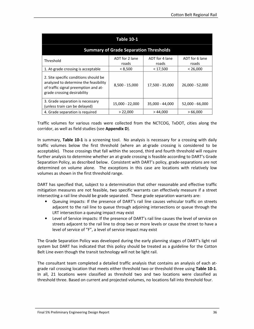
Cotton Belt Regional Rail
Final 5% Preliminary Engineering Design Report 36
Table 10-1
Summary of Grade Separation Thresholds
Threshold ADT for 2 lane
roads
ADT for 4 lane
roads
ADT for 6 lane
roads
1. At-grade crossing is acceptable < 8,500 < 17,500 < 26,000
2. Site specific conditions should be
analyzed to determine the feasibility
of traffic signal preemption and at-
grade crossing desirability
8,500 - 15,000 17,500 - 35,000 26,000 - 52,000
3. Grade separation is necessary
(unless train can be delayed) 15,000 - 22,000 35,000 - 44,000 52,000 - 66,000
4. Grade separation is required > 22,000 > 44,000 > 66,000
Traffic volumes for various roads were collected from the NCTCOG, TxDOT, cities along the
corridor, as well as field studies (see Appendix D).
In summary, Table 10-1 is a screening tool. No analysis is necessary for a crossing with daily
traffic volumes below the first threshold (where an at-grade crossing is considered to be
acceptable). Those crossings that fall within the second, third and fourth threshold will require
further analysis to determine whether an at-grade crossing is feasible according to DART’s Grade
Separation Policy, as described below. Consistent with DART’s policy, grade-separations are not
determined on volume alone. The exceptions in this case are locations with relatively low
volumes as shown in the first threshold range.
DART has specified that, subject to a determination that other reasonable and effective traffic
mitigation measures are not feasible, two specific warrants can effectively measure if a street
intersecting a rail line should be grade separated. These grade separation warrants are:
• Queuing impacts: If the presence of DART’s rail line causes vehicular traffic on streets
adjacent to the rail line to queue through adjoining intersections or queue through the
LRT intersection a queuing impact may exist
• Level of Service impacts: If the presence of DART’s rail line causes the level of service on
streets adjacent to the rail line to drop two or more levels or cause the street to have a
level of service of “F”, a level of service impact may exist
The Grade Separation Policy was developed during the early planning stages of DART’s light rail
system but DART has indicated that this policy should be treated as a guideline for the Cotton
Belt Line even though the transit technology will not be light rail.
The consultant team completed a detailed traffic analysis that contains an analysis of each at-
grade rail crossing location that meets either threshold two or threshold three using Table 10-1.
In all, 21 locations were classified as threshold two and two locations were classified as
threshold three. Based on current and projected volumes, no locations fall into threshold four.
Cotton Belt Regional Rail
Final 5% Preliminary Engineering Design Report 37
The grade separation recommendations in the draft report based on traffic analysis are made
using a combination of:
• The ITE Grade Separation Policy to determine which intersections need further
evaluation and,
• The DART Grade Separation Policy to determine if grade separation is necessary.
Therefore, based on projected 2030 traffic volumes, roadway geometry and location of the at-
grade rail crossing, the following roadway crossings are recommended for grade separation:
• Midway Road (threshold three)
• Coit Road (threshold three)
• Denton Tap Road (threshold two)
• Plano Parkway (threshold two)
• Luna Road (threshold two)
Although the traffic analysis for the Luna Road crossing suggests a need for a grade separation,
physical constraints given the presence of the adjacent PGBT overpass do not permit this
separation.
11.0 ENVIRONMENTAL CONSIDERATIONS An Alternatives and Environmental Considerations Report (AECR) was prepared for the
proposed Cotton Belt Corridor Regional Rail project. The AECR outlines the alternatives
considered and environmental analyses conducted to date. The AECR identifies the
environmental resources and existing conditions surrounding the Cotton Belt corridor from the
DFW Airport to Shiloh Road in Plano, Texas; provides background data for consideration of the
proposed project alternatives to be evaluated during the future National Environmental Policy
Act (NEPA) phase of the project once funding for project construction has been identified; and
identifies potential social, economic and environmental impacts of the proposed project.
Options for potential mitigation measures are also presented in the AECR. The AECR is
supported by a series of technical memoranda and reports prepared as part of the
environmental evaluation of alternatives and are appended to the AECR. Future designer should
review these documents for environmental concerns and consider any mitigation measures
specified within those documents. The following is a summary of environmental considerations
identified during this phase of the study.
11.1 Land Use
Residential areas comprise over 17 percent of the land use (2005 land use) in the study area.
Commercial and government/educational categories each comprise over 13 percent of the land
use in the corridor. Over 26 percent of the study area is classified as undeveloped which
includes under construction, vacant, parking, expanded parking and gravel. Remaining land use
in the corridor includes industrial, infrastructure, airports, dedicated (parks, landfill and flood
control) and water. The majority of the proposed Cotton Belt Regional Rail would follow the
existing Cotton Belt rail corridor. Therefore, there would not be a need to permanently impact
the land use of most of the project area. Since most development along the corridor occurred

Cotton Belt Regional Rail
Final 5% Preliminary Engineering Design Report 38
after the existing rail corridor was constructed, several industrial and warehouse areas were
developed along the corridor to have direct access to the rail for the transportation of goods.
11.2 Socioeconomic Characteristics including Environmental Justice
There are approximately 40 major employers (250 or more employees) within one-half mile of
the proposed rail stations and within one-quarter mile of the alignment. Major activity centers
in the study area include DFW Airport, Addison Airport, the University of Texas at Dallas (UTD) in
the City of Richardson and Addison Circle in the City of Addison.
Environmental Justice (EJ) populations have been identified within the Cotton Belt Corridor. EJ
populations include minority, low-income and Limited English Proficiency populations. At this
time, it is known that there are EJ populations near the proposed Downtown Carrollton Station,
Renner Village Station, UTD/Synergy Park Station and near US 75 to the eastern terminus at
Shiloh Road. Therefore, the proposed project would need to be evaluated for disproportionately
high and adverse human health or environmental effects to minority or low-income populations.
A final environmental justice determination would be made as part of future environmental
reviews under the NEPA process.
11.3 Acquisitions and Displacements
As described above, DART owns the Cotton Belt ROW; however, it is anticipated that property
acquisitions would occur. A preliminary assessment of properties that may be affected by
implementation of the proposed project is currently underway. Please refer to the Acquisitions
and Displacements Technical Memorandum.
11.4 Parks and Recreational Facilities
Numerous community parks, neighborhood parks, golf courses and recreational facilities are
adjacent to or located near the Cotton Belt Corridor rail alignment. Three regulations apply to
the use of parks and recreational facilities for transportation projects: Section 4(f) of the U. S.
Department of Transportation Act of 1966, Section 6(f) of the Land and Water Conservation
Fund (L&WCF) Act, and Texas Parks and Wildlife Code Title 3 Chapter 26. Publically owned
properties covered under Section 4(f) that may be affected by the proposed project include
Kelly Athletic Facilities, “City of Dallas Floodway Management Area 2” and “City of Dallas Public
Use Area” Future stages of project development should consider alternatives or methods to
avoid these properties. The proposed project has been reviewed for Section 6(f) involvement
and would not cause the conversion of any land acquired, planned or developed with funds
from L&WCF.
11.5 Cultural Resources
The proposed project would be constructed adjacent to the existing rail line and within the
current railroad ROW. The reconnaissance survey recorded 68 historic-age architectural
Cotton Belt Regional Rail
Final 5% Preliminary Engineering Design Report 39
resources within the project area of potential effect (APE) (refer to the Cultural Resources
Existing Conditions Technical Memorandum). Of these, none are currently listed in the National
Register of Historic Places (NRHP) and one (Addison State Bank - Resource 44) is listed as a
Registered Texas Historic Landmark. In total, three resources are recommended individually
eligible for inclusion in the NRHP: Addison State Bank (Resource 44); Carrollton Depot (Resource
21); and White Rock Creek Bridge (Resource 45). In addition, Resources 21 and 45 are
recommended as contributing resources to the Cotton Belt Railroad Thematic Corridor. Historic-
age resources that are within the APE, but outside the current railroad ROW would not be
impacted by the proposed project. One resource (White Rock Creek Bridge) located within the
ROW is recommended individually eligible for listing in the NRHP and recommended as a
contributing resource to the potential Cotton Belt Historic Railroad Thematic Corridor. Section
4(f) of the U. S. Department of Transportation Act of 1966, would also apply to the “use” of
White Rock Creek Bridge and may require additional evaluation pursuant to Section 4(f).
At present, no archaeological resources occur within the proposed Cotton Belt Corridor Regional
Rail ROW. Therefore, no known archaeological resources would be impacted by the proposed
actions. It should be noted, however, that an intensive archaeological survey within a defined
APE for archaeological resources has not been completed. Given the distribution and context of
previously recorded archaeological sites within the archaeological study area, the present
understanding of the occupational history of the region, and the occurrence of soils suitable for
the preservation of archaeological deposits, the proposed Cotton Belt Corridor Regional Rail
ROW has the potential to contain previously unrecorded archaeological resources.
11.6 Geology
Four geologic types underlie the project area – the Eagle Ford Formation, alluvium, fluviatile
terrace deposits, and Austin Chalk. One proposed alternative for the project would include a
tunnel which would pass through the Austin Chalk formation. Austin Chalk is known for
producing small-scale faulting. The formation is also susceptible to weathering due to erosion.
The occurrence of fossils in this formation is not common. Because Austin Chalk is a hard
formation with soft layers and faulting/weathered sections, special structural design measures
may be needed to strengthen tunnel walls in the vicinity of faults or layers (if the tunnel
alternative is selected).
11.7 Floodplains
FEMA floodplain maps were consulted for the project area (Map ID 48439C0115K,
48439C0120K, 48439C0110K, 48113C0135J and 48113C0345J, 48113C0155J, 48113C0160J,
48113C0180J, 48113C0185J, 48085C0485J, 48085C0505J, 48113C0065J, 48085C0390J, and
48085C0395J). According to the maps, three 100-year floodplains exist within the western half
of the project area. One crossing is a 100-year floodplain associated with Cottonwood Branch;
approximately 1,313 linear feet of this floodplain is crossed by the proposed project. The second
crossing is the 100-year floodplain associated with Grapevine Creek; approximately 3,350 linear
feet of this floodplain is crossed by the project. The third crossing is the 100-year floodplain
associated with Elm Fork Trinity River; approximately 9,488 feet of this floodplain is crossed by
the project. A crossing in the eastern half of the study area is the 100-year floodplain associated
with White Rock Creek; approximately 1,112 linear feet of this floodplain is crossed by the

Cotton Belt Regional Rail
Final 5% Preliminary Engineering Design Report 40
project. The tributary of White Rock Creek has a 100-year floodplain associated with it;
approximately 1,739 linear feet of this floodplain is crossed by the project.
A Trinity River Corridor Development Certificate (CDC) is required for projects located within the
Trinity River Regulatory Zone and is intended to minimize flood risk by regulating development
within the Trinity River Corridor in North Central Texas. The Trinity River Regulatory Zone is
consistent with the 100-year floodplain for the Trinity River, of which the Elm Fork of the Trinity
River is crossed by the project.
11.8 Water Quality
The study area is located within the Trinity River basin, which drains approximately 17,969
square miles. For the purposes of monitoring water quality, the Texas Commission on
Environmental Quality (TCEQ) has divided the Trinity River basin into 41 discrete segments. The
proposed project is located within Segment 0822 – Elm Fork Trinity River Below Lewisville Lake,
Segment 0822B – Grapevine Creek, and Segment 0827A – White Rock Creek. Defined uses of
Segments 0822 and 0822B include aquatic life use, contact recreation use, general use, and
public water supply. Defined uses of Segment 0827A include aquatic life use and contact
recreation use. According to the 2012 Section 303(d) list, none of the segments are listed as
impaired.
In Texas, the National Pollutant Discharge Elimination System (NPDES) permit program is
administered by the TCEQ, as part of the Texas Pollutant Discharge Elimination System (TPDES).
Stormwater runoff resulting from the proposed project would be addressed through compliance
with the TPDES Construction General Permit. More than five acres of earth disturbance would
occur as a result of the project; therefore, a Stormwater Pollution Prevention Program (SWPPP),
construction site notice, and Notice of Intent (NOI) would be required. Implementation of Best
Management Practices (BMPs) during construction, including erosion controls, sediment
controls, and/or post-construction total suspended solids controls, would reduce impacts to
water quality.
11.9 Noise and Vibration
The noise and vibration for the proposed was conducted is in conformance with the procedures
and criteria included in the Federal Transit Administration (FTA) guidance manual “Transit Noise
and Vibration Impact Assessment” (Final Report No. FTA-VA-90-1003-06, May 2006), and in the
DART policy document “Environmental Impact Assessment and Mitigation Guidelines for Transit
Projects” (May 2012).
The results of the noise impact assessment identified noise impacts at a total of 3880 receptors
without mitigation, including 2652 severe impacts and 1228 moderate impacts for the Baseline
Alternative with the At-Grade Alternative through North Dallas and the North Alignment
Alternative. Without mitigation, the primary cause of potential noise impact for the Cotton Belt
Corridor is noise from train horns that would be sounded at the numerous at-grade crossings
along the alignment. Thus, the primary recommended mitigation measure is the
implementation of quiet zones throughout the project corridor. Over 95 percent of all noise

Cotton Belt Regional Rail
Final 5% Preliminary Engineering Design Report 41
impacts would be eliminated with the implementation of quiet zones throughout the corridor.
Remaining noise impacts can be mitigated through various measures for reducing noise impacts.
The results of the vibration impact assessment identified potential ground-borne vibration
impact at a total of five receptors without mitigation for the Baseline Alternative and at two
receptors with the Cypress Waters Alternative. For the North Dallas Tunnel Alternative, a total
of 32 potential ground-borne noise impacts are identified. There are no vibration impacts
predicted for the South Alignment Alternative with Aerial Station and Depressed Freight. There
are various vibration mitigation measures that can be implemented. Additional analysis should
be conducted during later stages of the project to determine specific vibration mitigation
measures.
11.10 Air Quality
An air quality impact analysis was not conducted during this phase of the project. If the
proposed project advances, an air quality impact analysis may be required based on the criteria
defined by the FTA environmental process. A project-level conformity determination is also
required for the project because it is a nonexempt project in a non-attainment area for ozone.
FTA cannot approve funding for project activities beyond preliminary engineering unless the
proposed project meets EPA transportation conformity regulations at the project level. The
project is included in the North Central Texas Council of Governments (NCTCOG) Transportation
Conformity. In addition, NCTCOG has demonstrated that Mobility 2035: The Metropolitan
Transportation Plan for North Central Texas and 2011-2014 Transportation Improvement
Program for North Central Texas – 2011 Amendment meet all transportation air quality
conformity requirements of the CAAA, the air quality plan, the transportation conformity rule
and transportation conformity related provisions contained in the Safe, Accountable, Flexible,
Efficient Transportation Equity Act: A Legacy for Users (SAFETEA-LU) (NCTCOG, 2011).
11.11 Hazardous Materials
A search of the regulatory databases for sites that handle, generate, transport, store, or dispose
of hazardous and/or regulated materials was conducted by Environmental Data Resources, Inc.
(EDR). The EDR report was generated for the one-half mile radius of the Cotton Belt corridor and
was reviewed for potential hazardous site. From the database a total of 26 potential Hazmat
sites were identified. However, out of 26 sites, two sites are rated high risk due to chlorinated
solvent contamination in the soil, eight as medium risk, and the remaining 16 were rated as a
low potential to impact construction activities. Based on the current alignment, it appears that
none of the identified high or medium risk sites are within the construction area where
subsurface soil would be disturbed during the construction activities hence, should not pose a
risk. However, if current alignment changes, then further evaluation of the sites may be
required to determine the Hazmat risk. There may be a potential for a Hazmat risk area near the
US 75 intersection if subsurface soil is disturbed during construction activities. There are two
Hazmat sites (Refer to the Hazardous Materials Technical Memorandum, August 2013, Map ID
42 and 48) on either side of the US 75 which are in medium risk category. Map ID 42 site,
located at 810 North Central Express Parkway, is a dry cleaning facility and the site soil is
contaminated with chlorinated solvents. Map ID 48 is a Leaking Petroleum Storage Tank (LPST)
site located at 625 North Central Express Parkway and the site groundwater is contaminated.
Cotton Belt Regional Rail
Final 5% Preliminary Engineering Design Report 42
The existing DART railroad track goes over US 75. If the existing bridge is replaced and
subsurface soil is disturbed for pillar construction, then there is a potential for the Hazmat risk.
From the site reconnaissance conducted on November 13, 21, 29, and December 3, 2012, no
significant environmental impact related to hazardous materials was observed along the 26-mile
Cotton Belt Corridor, either on existing DART right-of-way property or adjacent properties.
However, a few spills and stains were observed on the track as well as household trash on
properties adjacent to the right-of-way.
11.12 Water Resources
The water resources study area used for the assessment of potential impacts included a one-
quarter-mile corridor centered on the project centerline. A Preliminary Draft Jurisdictional
Determination report, August 2013, was prepared during this phase of the study to identify,
delineate, and describe jurisdictional wetlands and other waters of the U.S. Conclusions
contained in the draft report are subject to confirmation by the USACE. Twenty-seven potential
waters of the U.S., including three wetlands, lie within the proposed right of way. The proposed
project has the potential to affect approximately five acres of waters of the U.S. within the
proposed right of way. Impacts to waters of the U.S. resulting from the discharge of dredged or
fill material are regulated by the USACE under Section 404 of the Clean Water Act. If a linear
transportation project places less than 0.5 acre of fill into waters of the U.S., it would typically
be authorized under Nationwide Permit (NWP) 14; impacts of more than 0.5 acre require an
Individual Permit. Impacts authorized under a NWP-Linear Transportation Projects which equal
or exceed 0.1 acre require Pre-Construction Notification (PCN) to the USACE; impacts to
wetlands (of any amount) would also require PCN.
Section 408 of the Clean Water Act requires that projects which would take possession of, use,
or cause injury to harbor or river improvements be reviewed and approved by the USACE. No
facilities subject to Section 408 have been identified within the proposed right-of-way.
11.13 Biological Resources
Existing literature and mapping were reviewed for the project area to identify soils, potential
vegetative communities, potential wildlife assemblages, potential wetland areas, and
threatened or endangered species of potential occurrence.
Detailed field investigations were performed in March 2013 to assess the specific vegetation
types and species occurring within and adjacent to the project corridor. In general, the project
corridor contains vegetation commonly found in the Cross Timbers and Blackland Prairie Natural
Regions. No crops were found in the project area. The proposed project corridor crosses the
communities of Grapevine, Coppell, Dallas, Carrollton, Addison, Plano, and Richardson. All of
these municipalities have tree protection ordinances in place. According to the ordinances,
removal or alteration of trees on public property require permits from the city in question.
Some of these cities also have protection provisions in place for trees on private property. Any
tree removals would need to be done in accordance with city ordinances and permits would
need to be obtained if necessary.

Cotton Belt Regional Rail
Final 5% Preliminary Engineering Design Report 43
According to data obtained from the Natural Diversity Database from Texas Parks and Wildlife
Department, one rookery utilized by Snowy Egrets (Egretta thula), Little Blue Herons (Egretta
caerulea), and Cattle Egrets (Bubulcus ibis) has been reported to occur within the central portion
of the project area. During field investigations, no rookeries were noted within or adjacent to
the project corridor.
Federally listed species and their habitats are protected under the Endangered Species Act of
1973 (16 U.S.C. 1531-1544, 87 Stat. 884), as amended. No potential habitat for federally listed
species was identified within the project area, therefore it is anticipated that the proposed
project would have no effect on federally-listed species for Tarrant, Dallas and Collin Counties.
Eight state-listed threatened species could occur in the project area including the alligator
snapping turtle (Macrochelys temminckii), canebrake rattlesnake (Crotalus horridus), Bald Eagle
(Haliaeetus leucocephalus), White-faced Ibis (Plegadis chihi), Wood Stork (Mycteria Americana),
Louisiana pigtoe (Pleurobema riddellii), Texas pigtoe (Fusconaia askewi) and the Texas
heelsplitter (Potamilus amphichaenus). The latter three species (Louisiana pigtoe, Texas pigtoe,
Texas heelsplitter), all have element of occurrences within 0.7 – 8 miles from the project area.
The project may impact these eight state-listed species if they are present within the project
area. The proposed project would have no impact on any other state-listed threatened species.
Five state-listed species of concern could occur in the project area including fawnsfoot (Truncilla
donaciformis), little spectaclecase (Villosa lienosa), Wabash pigtoe (Fusconaia flava), Texas
garter snake (Thamnophis sirtalis annectens) and plains spotted skunk (Spilogale putorius
interrupta). The Texas garter snake has two element of occurrences (ID 432) 9.3 miles south of
study area and (ID 434) 7.1 miles north of the project area.
Replacement of bridges over rivers may impact water species. However, use of BMPs would
avoid or minimize water quality impacts to the river, thus avoiding impacts to the species.
State law prohibits direct harm for state-listed species, but does not currently provide for
habitat protection. If any individuals of state-listed species are encountered within the project
area during construction, care should be taken to avoid harming them.
Several swallow (unknown species) nests were identified under the President George Bush
Turnpike along the South Alignment in Richardson. Although these species are not listed as
threatened or endangered, they would fall under the protection of the Migratory Bird Treaty Act
and any work done in this area would need to be avoided during nesting season.
12.0 GEOTECHNICAL CONSIDERATIONS Soil borings and geotechnical analysis will be performed after the Cotton Belt 5% PE submittal.
The geotechnical information will be provided in the 10% PE design package.
13.0 SYSTEM ELEMENTS The methodology provides an integrated approach to design, construction, and commissioning
with emphasis on ensuring a systematic and detailed coordination effort linking all design
disciplines starting at the earliest design stages. The real challenge with systems engineering is
not only designing the specific systems elements, it is in integrating systems and sub-systems
together to make them function seamlessly as one comprehensive system.

Cotton Belt Regional Rail
Final 5% Preliminary Engineering Design Report 44
The Cotton Belt systems planning scope consists of conceptual design for the following primary
systems and sub-systems: Positive Train Control (PTC), Wayside Signal, Highway Grade Crossing,
and Communication Systems.
The following is a general overview of the design methodology and criteria for these systems
that will be required for the Cotton Belt Regional Rail Project. Guidance documents with typical
design details are included in App
13.1 Positive Train Control
The Rail Safety Improvement Act of 2008(RSI08) requires all railroads providing regularly
scheduled intercity passenger service to implement a fully functional PTC Signal System by
December 31, 2015. RSI08 was enacted in response to several recent high profile train accidents
involving multiple fatalities.
Positive Train Control (PTC) systems are integrated command and control, communications, and
information systems that operate together to control train movements ensuring safety, security,
precision, and efficiency of rail operations. PTC systems improve railroad safety by significantly
reducing the probability of railroad accidents including: train collisions, train intrusion into
established work zones, collisions between trains and on-track equipment, and over speed
derailments.
PTC systems are comprised of digital data link communications networks, continuous and
accurate positioning systems such as NDGPS, on-board computers with digitized maps on
locomotives and maintenance-of-way equipment, in-cab displays, throttle-brake interfaces on
locomotives, wayside interface units at switch machines, wayside detectors, and control center
computers and displays.
13.2 Wayside Signals
There are three basic types of wayside signal systems: Automatic Block Signal (ABS), Interlocking
(INT), and Traffic Control System (TCS) commonly called Centralized Traffic Control (CTC). On rail
lines equipped with Block Signal Systems, wayside signals located along the tracks generally
display indications to a train engineer to proceed, slow down, or stop. Signal indications are
commonly displayed by illuminated green, yellow, or red aspects respectively (or an equivalent
scheme including some that are not colored). The wayside signal systems provides additional
information regarding: rail integrity (broken or missing rail), train occupancy (a train in the
“block” or section of track governed by the signal), and/or the position of track switches in the
block.
The wayside block signaling sections use fixed wayside signals at interlockings and Automatic
Block Signals (ABS) between interlockings. Signals are spaced to provide required design
headways. In CTC territory signals at each control point can be managed directly by a dispatcher
located at the Train Control Center (TCC). Dispatchers can control routes for specific trains;
remotely control track switches, and operate signals to display the desired proceed indications.
CTC technology utilizes vital wayside signal system logic to ensure that route integrity is
Cotton Belt Regional Rail
Final 5% Preliminary Engineering Design Report 45
preserved and appropriate signal locking logic is provided prior to signals displaying proceed
indications.
Vital wayside train-control functions are generated utilizing vital microprocessors. Vital plug-in
relays are used for specific applications. All non-vital functions performed using non-vital
microprocessors. The Signal System technology ensures safe and reliable control of the
operation of trains utilizing the rail system. The system design shall be fail-safe and provide safe
degraded operating modes. A vital function is any circuit or software logic that can affect the
safety of train operations. All vital functions shall meet fail safe design principles. Fail Safe
Design Criteria - Vital logic design shall be based on closed loop circuit principals with the train
operator considered as an active element.
13.3 Highway Grade Crossing Signals
Signal systems at highway grade crossings will include all signs, signals, warning devices, and
their supports located within the rail right-of-way. The function of these systems will permit safe
and efficient operation of commuter trains, on track equipment, highway traffic, and
pedestrians over level grade crossings. Grade crossing warning devices shall be designed in
conformance with the Texas Manual on Uniform Traffic Control Devices (TXMUTCD), TXDOT,
and the recommended American Railway Engineering and Maintenance-of-Way (AREMA)
practices.
Highway rail grade crossing warning systems shall be maintained to operate in compliance with
the design of the warning system, but in no event shall they provide less than 20 seconds
warning time for the operation of through trains before grade crossings are occupied by rail
traffic.
13.4 Communication Systems
This section describes the functional and interface criteria to be designed into all Commuter Rail
Communication Systems. System provisions shall meet the requirements of all applicable
standard and directive drawings and shall be coordinated with the agency. Subsystems shall be
compliant with federal, state, and local laws such as the Americans with Disabilities Act (ADA)
and applicable National Fire Prevention Association (NFPA) codes and standards relating to
public transportation and communications systems.
The Communications System shall consist of the following subsystems:
• Communication Transmission Subsystem
• Radio Subsystem - Rail
• Closed Circuit Television (CCTV) Subsystem
• Public Address and Visual Message Board (PA/VMB) Subsystem
• Telephone Subsystem
• Administrative Telephone
• Passenger Emergency Call
• Emergency Telephone
• Wayside Telephone
• Fire Detection Subsystem
Cotton Belt Regional Rail
Final 5% Preliminary Engineering Design Report 46
• Intrusion Detection Subsystem
The Communications Transmission Subsystem provides the medium for point-to-point, shared
voice, and data transmission. It consists of transmission, multiplexing and inter-connect
equipment and provides interfaces for all terminal equipment requiring connectivity from field
communicating sites to the Operations Control Center (OCC).
1. The Radio Subsystem shall consist of the following parts: Two-way communications to
support rail operations, maintenance and public safety, and project build-out.
2. CCTV shall be provided at all passenger stations to enhance operations and security. The
design shall adequately accommodate signal, power and control cabling.
3. PA/VMB shall be provided at all Passenger stations. PA/VMB equipment shall allow
communication with patrons or employees, as appropriate during emergency or
interruptions of train service equipment shall be designed to comply with ADA
accessibility guidelines.
4. The Telephone Subsystem shall provide emergency and administrative voice and dial-up
data services to communications devices throughout the rail system. These devices
include administrative telephones, passenger emergency call (PEC) units, elevator
emergency telephones, wayside telephones, and digital communications alarm
transmitter (DACT) units. The system shall allow communications between and among
various field facilities and the Operations Control Center and enable communications
between Commuter Rail field facilities.
5. All fire detection equipment shall conform to the latest requirements of National Fire
Protection Association NFPA Codes Section 12A, 72, 72-90 and 130.
6. Intrusion Detection Subsystem shall provide intrusion detection and alarming
equipment at communications houses, interface cabinets, facilities and rooms.

Cotton Belt Regional Rail
Final 5% Preliminary Engineering Design Report 47
Appendix A: Cotton Belt Existing Utility/Crossing Lists

Cotton Belt Regional Rail
Final 5% Preliminary Engineering Design Report 48
Cotton Belt Section CB-1 Existing Crossing List
DWG. NO. Station Utility/Crossing Size Owner
CC2-1005 1022+50 Overhead Line
CC2-1005 1023+00 Drainage Pipe Culvert 60” City of Grapevine
CC2-1005 -
CC2-1048 1026+00 1387+96 Fiber optic longitudinal Sprint
CC2-1005 -
CC2-1048 1026+00 1387+96 Fiber optic longitudinal Qwest
CC2-1005 1024+56 Gas pipeline crossing 12" Chesapeake
CC2-1005 1025+03 Saltwater line with 16" steel casing crossing 10" Chesapeake
CC2-1005 1026+46 Fiber optic crossing Qwest
CC2-1007 1042+17 Petroleum pipeline crossing 8" Explorer Pipeline
CC2-1008 1051+35 Cottonwood Creek Crossing (Bridge) 80-feet City of Grapevine
CC2-1009 1054+55 Saltwater line with 16" steel casing crossing 10" Chesapeake
CC2-1009 1054+67 Gas pipeline crossing 24" Chesapeake
CC2-1009 1060+12 Cottonwood Creek Crossing (Bridge) 64-feet City of Grapevine
CC2-1010 -
CC2-1029 1065+38 1217+29 Fiber optic longitudinal Verizon Tel
CC2-1010 1067+47 Lighting OHE crossing
CC2-1011 1070+11 Lighting OHE crossing
CC2-1011 1072+96 Two - Pipe/Box culvert across the existing rail. 2 - 30" City of Grapevine
CC2-1011 1072+96 Drainage crossing
CC2-1011 1074+34 Gas pipeline high pressure crossing 4" Atmos
CC2-1012 1078+96 UG telecommunication conduit crossing 3" Verizon Tel
CC2-1012 1083+23 Gas pipeline crossing 24" Chesapeake
CC2-1012 1083+40 Saltwater line with 16" steel casing crossing 10" Chesapeake
CC2-1013 1091+99 Drainage crossing 2 - 24” City of Grapevine
CC2-1014 1101+59 Gas pipeline high pressure crossing 4" Atmos
CC2-1015 1102+07 Saltwater line with 16" steel casing crossing 10" Chesapeake
CC2-1015 1102+22 Gas pipeline crossing 10" Chesapeake
CC2-1015 1102+37 Saltwater line with 16" steel casing crossing 10" Chesapeake
CC2-1015 1102+53 Gas pipeline crossing 10" Chesapeake
CC2-1015 1105+79 Drainage Pipe Culvert 2 – 27” City of Grapevine
CC2-1016 1113+35 Drainage Pipe/Box Culvert across existing rail. 60” City of Coppell
CC2-1017 1122+20 Drainage Pipe Culvert across existing rail. 24” City of Coppell
CC2-1018 1129+41 Water line crossing 16" City of Coppell
CC2-1018 1129+50 Storm Drain 39” City of Coppell
CC2-1018 1129+33 Drainage Pipe Culvert parallel to rail on the North 30” City of Coppell
CC2-1018 1129+33 Drainage Pipe Culvert parallel to rail on the South 27” City of Coppell
CC2-1018 1129+72 Two UG 1.25" FO cables with 4" steel casing crossing 4" Time Warner Cable
CC2-1018 1129+76 Sanitary sewer crossing 12" City of Coppell
CC2-1018 1129+80 Two UG telecommunication cables crossing 4" Verizon Tel
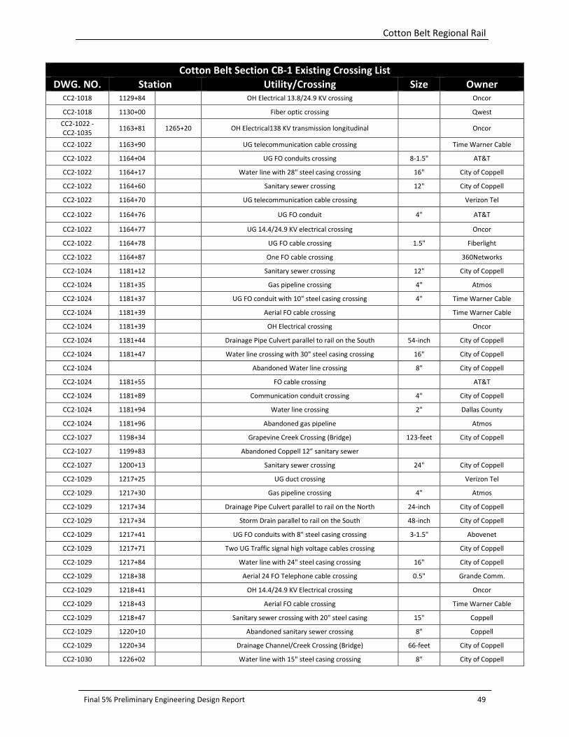
Cotton Belt Regional Rail
Final 5% Preliminary Engineering Design Report 49
Cotton Belt Section CB-1 Existing Crossing List
DWG. NO. Station Utility/Crossing Size Owner CC2-1018 1129+84 OH Electrical 13.8/24.9 KV crossing Oncor
CC2-1018 1130+00
Fiber optic crossing
Qwest
CC2-1022 -
CC2-1035 1163+81 1265+20 OH Electrical138 KV transmission longitudinal Oncor
CC2-1022 1163+90 UG telecommunication cable crossing Time Warner Cable
CC2-1022 1164+04 UG FO conduits crossing 8-1.5" AT&T
CC2-1022 1164+17 Water line with 28" steel casing crossing 16" City of Coppell
CC2-1022 1164+60 Sanitary sewer crossing 12" City of Coppell
CC2-1022 1164+70 UG telecommunication cable crossing Verizon Tel
CC2-1022 1164+76 UG FO conduit 4" AT&T
CC2-1022 1164+77 UG 14.4/24.9 KV electrical crossing Oncor
CC2-1022 1164+78 UG FO cable crossing 1.5" Fiberlight
CC2-1022 1164+87 One FO cable crossing 360Networks
CC2-1024 1181+12 Sanitary sewer crossing 12" City of Coppell
CC2-1024 1181+35 Gas pipeline crossing 4" Atmos
CC2-1024 1181+37 UG FO conduit with 10" steel casing crossing 4" Time Warner Cable
CC2-1024 1181+39 Aerial FO cable crossing Time Warner Cable
CC2-1024 1181+39 OH Electrical crossing Oncor
CC2-1024 1181+44 Drainage Pipe Culvert parallel to rail on the South 54-inch City of Coppell
CC2-1024 1181+47 Water line crossing with 30" steel casing crossing 16" City of Coppell
CC2-1024 Abandoned Water line crossing 8" City of Coppell
CC2-1024 1181+55 FO cable crossing AT&T
CC2-1024 1181+89 Communication conduit crossing 4" City of Coppell
CC2-1024 1181+94 Water line crossing 2" Dallas County
CC2-1024 1181+96 Abandoned gas pipeline Atmos
CC2-1027 1198+34 Grapevine Creek Crossing (Bridge) 123-feet City of Coppell
CC2-1027 1199+83 Abandoned Coppell 12” sanitary sewer
CC2-1027 1200+13 Sanitary sewer crossing 24" City of Coppell
CC2-1029 1217+25 UG duct crossing Verizon Tel
CC2-1029 1217+30 Gas pipeline crossing 4" Atmos
CC2-1029 1217+34 Drainage Pipe Culvert parallel to rail on the North 24-inch City of Coppell
CC2-1029 1217+34 Storm Drain parallel to rail on the South 48-inch City of Coppell
CC2-1029 1217+41 UG FO conduits with 8" steel casing crossing 3-1.5" Abovenet
CC2-1029 1217+71 Two UG Traffic signal high voltage cables crossing City of Coppell
CC2-1029 1217+84 Water line with 24" steel casing crossing 16" City of Coppell
CC2-1029 1218+38 Aerial 24 FO Telephone cable crossing 0.5" Grande Comm.
CC2-1029 1218+41 OH 14.4/24.9 KV Electrical crossing Oncor
CC2-1029 1218+43 Aerial FO cable crossing Time Warner Cable
CC2-1029 1218+47 Sanitary sewer crossing with 20" steel casing 15" Coppell
CC2-1029 1220+10 Abandoned sanitary sewer crossing 8" Coppell
CC2-1029 1220+34 Drainage Channel/Creek Crossing (Bridge) 66-feet City of Coppell
CC2-1030 1226+02 Water line with 15" steel casing crossing 8" City of Coppell
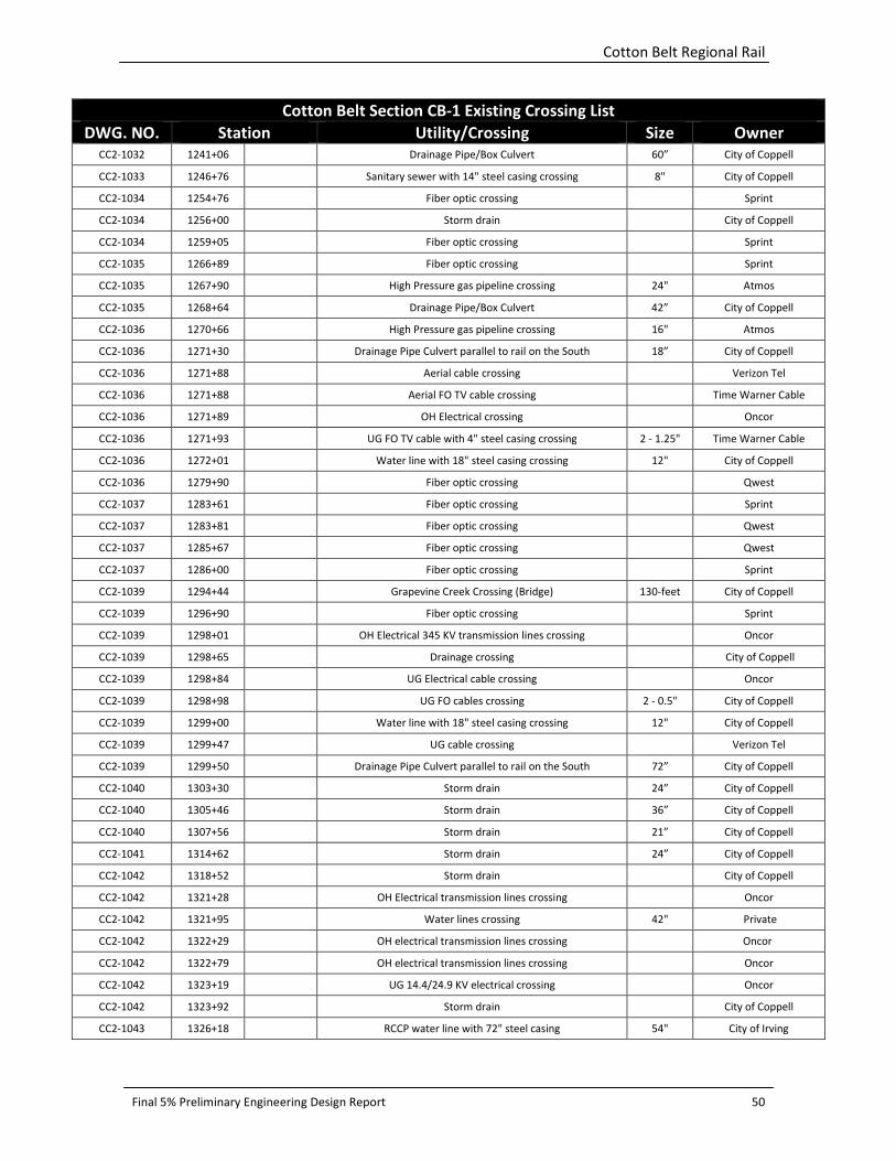
Cotton Belt Regional Rail
Final 5% Preliminary Engineering Design Report 50
Cotton Belt Section CB-1 Existing Crossing List
DWG. NO. Station Utility/Crossing Size Owner CC2-1032 1241+06 Drainage Pipe/Box Culvert 60” City of Coppell
CC2-1033 1246+76 Sanitary sewer with 14" steel casing crossing 8" City of Coppell
CC2-1034 1254+76 Fiber optic crossing Sprint
CC2-1034 1256+00
Storm drain
City of Coppell
CC2-1034 1259+05 Fiber optic crossing Sprint
CC2-1035 1266+89 Fiber optic crossing Sprint
CC2-1035 1267+90 High Pressure gas pipeline crossing 24" Atmos
CC2-1035 1268+64 Drainage Pipe/Box Culvert 42” City of Coppell
CC2-1036 1270+66 High Pressure gas pipeline crossing 16" Atmos
CC2-1036 1271+30 Drainage Pipe Culvert parallel to rail on the South 18” City of Coppell
CC2-1036 1271+88 Aerial cable crossing Verizon Tel
CC2-1036 1271+88 Aerial FO TV cable crossing Time Warner Cable
CC2-1036 1271+89 OH Electrical crossing Oncor
CC2-1036 1271+93 UG FO TV cable with 4" steel casing crossing 2 - 1.25" Time Warner Cable
CC2-1036 1272+01 Water line with 18" steel casing crossing 12" City of Coppell
CC2-1036 1279+90 Fiber optic crossing Qwest
CC2-1037 1283+61 Fiber optic crossing Sprint
CC2-1037 1283+81 Fiber optic crossing Qwest
CC2-1037 1285+67 Fiber optic crossing Qwest
CC2-1037 1286+00 Fiber optic crossing Sprint
CC2-1039 1294+44 Grapevine Creek Crossing (Bridge) 130-feet City of Coppell
CC2-1039 1296+90 Fiber optic crossing Sprint
CC2-1039 1298+01 OH Electrical 345 KV transmission lines crossing Oncor
CC2-1039 1298+65 Drainage crossing City of Coppell
CC2-1039 1298+84 UG Electrical cable crossing Oncor
CC2-1039 1298+98 UG FO cables crossing 2 - 0.5" City of Coppell
CC2-1039 1299+00 Water line with 18" steel casing crossing 12" City of Coppell
CC2-1039 1299+47 UG cable crossing Verizon Tel
CC2-1039 1299+50 Drainage Pipe Culvert parallel to rail on the South 72” City of Coppell
CC2-1040 1303+30 Storm drain 24” City of Coppell
CC2-1040 1305+46 Storm drain 36” City of Coppell
CC2-1040 1307+56 Storm drain 21” City of Coppell
CC2-1041 1314+62 Storm drain 24” City of Coppell
CC2-1042 1318+52 Storm drain City of Coppell
CC2-1042 1321+28 OH Electrical transmission lines crossing Oncor
CC2-1042 1321+95 Water lines crossing 42" Private
CC2-1042 1322+29
OH electrical transmission lines crossing Oncor
CC2-1042 1322+79 OH electrical transmission lines crossing Oncor
CC2-1042 1323+19 UG 14.4/24.9 KV electrical crossing Oncor
CC2-1042 1323+92 Storm drain City of Coppell
CC2-1043 1326+18 RCCP water line with 72" steel casing 54" City of Irving
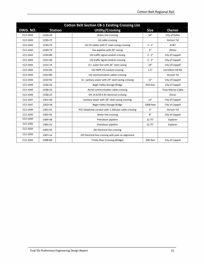
Cotton Belt Regional Rail
Final 5% Preliminary Engineering Design Report 51
Cotton Belt Section CB-1 Existing Crossing List
DWG. NO. Station Utility/Crossing Size Owner CC2-1043 1326+50 Water line crossing 54" City of Dallas
CC2-1043 1330+72 UG cable crossing Verizon Tel
CC2-1043 1330+73 UG FO cables with 4" steel casing crossing 3 - 1" AT&T
CC2-1043 1330+74 Gas pipeline with 10" casing 6" Atmos
CC2-1043 1330+80 UG traffic signal conduit crossing 2 - 2" City of Coppell
CC2-1043 1331+36 UG traffic signal conduit crossing 2 - 2" City of Coppell
CC2-1043 1331+74 D.I. water line with 36" steel casing 24" City of Coppell
CC2-1043 1331+83 UG HDPE FO conduit crossing 1.5" Carrollton-FB ISD
CC2-1043 1331+90 UG communication cables crossing Verizon Tel
CC2-1043 1333+92 D.I. sanitary sewer with 24" steel casing crossing 12" City of Coppell
CC2-1044 1336+26 Begin Valley Storage Bridge 910-feet City of Coppell
CC2-1044 1338+23 Aerial communication cable crossing Time Warner Cable
CC2-1044 1338+23 OH 14.4/29.4 KV electrical crossing Oncor
CC2-1047 1361+34 Sanitary sewer with 18" steel casing crossing 12" City of Coppell
CC2-1047 1362+38 Begin Valley Storage Bridge 1008-feet City of Coppell
CC2-1049 1381+55 PVC telephone conduit with 1-200 pair cable crossing 4" Verizon Tel
CC2-1050 1382+91 Water line crossing 8" City of Coppell
CC2-1050 1384+48 Petroleum pipeline 12.75” Explorer
CC2-1050 1385+22 Petroleum pipeline 12.75” Explorer
CC2-1050 1385+95
OH Electrical line crossing
CC2-1050 1387+14
OH Electrical line crossing with pole on alignment
CC2-1050 1388+60
Trinity River Crossing (Bridge) 246-feet City of Coppell

Cotton Belt Regional Rail
Final 5% Preliminary Engineering Design Report 52
Cotton Belt Section CB-2 Existing Crossing List
DWG. NO. Station Utility/Crossing Size Owner
CC2-2002 2017+52 Fiber optic crossing Qwest
CC2-2002 2017+32 Underground Telephone Qwest
CC2-2002 2018+24 Petroleum Line 12.75" Explorer
CC2-2002 2018+86 Water 12" City of Carrollton
CC2-2002 2019+55 Sanitary Sewer 10" City of Carrollton
CC2-2006 2043+91 2050+43 Overhead Electric Oncor
CC2-2006 -
CC2-2007 2050+45 2054+12 Underground Electric Oncor
CC2-2007 2053+98 Sanitary Sewer 60" City of Carrollton
CC2-2007 2055+07 Water 24" City of Carrollton
CC2-2007 2055+13 Overhead Electric Oncor
CC2-2007 -
CC2-2010 2059+14 2081+35 Sanitary Sewer 33" City of Carrollton
CC2-2007 2059+21 Gas 8" Atmos
CC2-2007 2059+60 Storm Drain Crossing 60" CMP City of Carrollton
CC2-2010 2076+00 Sanitary Sewer 12" City of Carrollton
CC2-2010 2081+33 Sanitary Sewer 33" City of Carrollton
CC2-2010 2081+55 Sanitary Sewer 42" City of Carrollton
CC2-2010 2082+02 Water 12" City of Carrollton
CC2-2011 2086+48 Overhead Electric Oncor
CC2-2011 2087+01 Overhead Electric Oncor
CC2-2011 -
CC2-2013 2087+36 2101+69 Overhead Electric Oncor
CC2-2012 2092+00 Petroleum Line 12.75" Explorer
CC2-2012 2097+46 Overhead Electric Oncor
CC2-2012 2079+58
Telephone
Verizon
CC2-2012 2097+65 Underground Telephone Verizon
CC2-2012 2097+73 Water 12" City of Carrollton
CC2-2013 2101+00 Storm Drain Crossing 33" RCP TxDOT
CC2-2013 2101+14
Gas 4" Atmos
CC2-2013 2101+36 Gas 4" Atmos
CC2-2013 2101+36 Underground Telephone
Williams
CC2-2013 2101+42
Water 6" City of Carrollton
CC2-2013 2101+52 Petroleum Line 12.75" Explorer
CC2-2013 2101+81 Overhead Electric / Telephone Oncor And Verizon
CC2-2013 2105+45 Petroleum line 12.75" Explorer
CC2-2013 2105+79 Overhead Electric Oncor
CC2-2013 2105+85 Storm Drain Crossing 30" RCP DART
CC2-2013 2106+00
Underground Telephone
Verizon
CC2-2013 2106+19 Water 12" City of Carrollton
CC2-2013 2106+44 Water 66" City of Dallas
CC2-2013 2107+17 Storm Drain Crossing 27" RCP DART
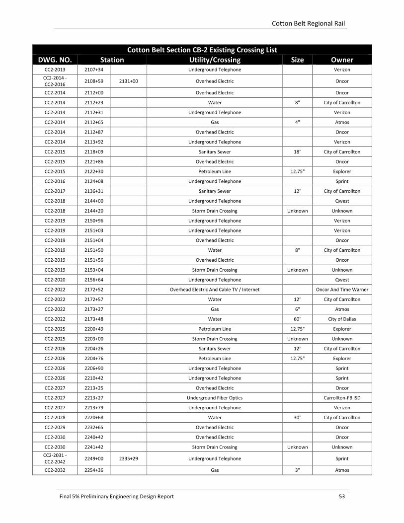
Cotton Belt Regional Rail
Final 5% Preliminary Engineering Design Report 53
Cotton Belt Section CB-2 Existing Crossing List
DWG. NO. Station Utility/Crossing Size Owner
CC2-2013 2107+34 Underground Telephone Verizon
CC2-2014 -
CC2-2016 2108+59 2131+00 Overhead Electric Oncor
CC2-2014 2112+00 Overhead Electric Oncor
CC2-2014 2112+23 Water 8" City of Carrollton
CC2-2014 2112+31 Underground Telephone Verizon
CC2-2014 2112+65 Gas 4" Atmos
CC2-2014 2112+87 Overhead Electric Oncor
CC2-2014 2113+92 Underground Telephone Verizon
CC2-2015 2118+09 Sanitary Sewer 18" City of Carrollton
CC2-2015 2121+86 Overhead Electric Oncor
CC2-2015 2122+30 Petroleum Line 12.75" Explorer
CC2-2016 2124+08 Underground Telephone Sprint
CC2-2017 2136+31 Sanitary Sewer 12" City of Carrollton
CC2-2018 2144+00
Underground Telephone
Qwest
CC2-2018 2144+20 Storm Drain Crossing Unknown Unknown
CC2-2019 2150+96 Underground Telephone Verizon
CC2-2019 2151+03
Underground Telephone
Verizon
CC2-2019 2151+04 Overhead Electric Oncor
CC2-2019 2151+50 Water 8" City of Carrollton
CC2-2019 2151+56 Overhead Electric Oncor
CC2-2019 2153+04 Storm Drain Crossing Unknown Unknown
CC2-2020 2156+64 Underground Telephone Qwest
CC2-2022 2172+52 Overhead Electric And Cable TV / Internet Oncor And Time Warner
CC2-2022 2172+57 Water 12" City of Carrollton
CC2-2022 2173+27 Gas 6" Atmos
CC2-2022 2173+48 Water 60" City of Dallas
CC2-2025 2200+49 Petroleum Line 12.75" Explorer
CC2-2025 2203+00 Storm Drain Crossing Unknown Unknown
CC2-2026 2204+26 Sanitary Sewer 12" City of Carrollton
CC2-2026 2204+76 Petroleum Line 12.75" Explorer
CC2-2026 2206+90 Underground Telephone Sprint
CC2-2026 2210+42 Underground Telephone Sprint
CC2-2027 2213+25 Overhead Electric Oncor
CC2-2027 2213+27 Underground Fiber Optics Carrollton-FB ISD
CC2-2027 2213+79 Underground Telephone Verizon
CC2-2028 2220+68 Water 30" City of Carrollton
CC2-2029 2232+65 Overhead Electric Oncor
CC2-2030 2240+42 Overhead Electric Oncor
CC2-2030 2241+42 Storm Drain Crossing Unknown Unknown
CC2-2031 -
CC2-2042 2249+00 2335+29 Underground Telephone Sprint
CC2-2032 2254+36 Gas 3" Atmos
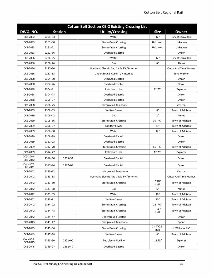
Cotton Belt Regional Rail
Final 5% Preliminary Engineering Design Report 54
Cotton Belt Section CB-2 Existing Crossing List
DWG. NO. Station Utility/Crossing Size Owner
CC2-2032 2254+63 Water 12" City of Carrollton
CC2-2033 2261+00 Storm Drain Crossing Unknown Unknown
CC2-2033 2261+21 Storm Drain Crossing Unknown Unknown
CC2-2033 2262+56 Overhead Electric Oncor
CC2-2036 2286+25 Water 12" City of Carrollton
CC2-2036 2286+76 Gas 6" Atmos
CC2-2036 2287+30 Overhead Electric And Cable TV / Internet Oncor And Time Warner
CC2-2036 2287+53 Underground Cable TV / Internet Time Warner
CC2-2038 2304+00 Overhead Electric Oncor
CC2-2038 2304+26 Overhead Electric Oncor
CC2-2038 2304+31 Petroleum Line 12.75" Explorer
CC2-2038 2304+73 Overhead Electric Oncor
CC2-2038 2305+07 Overhead Electric Oncor
CC2-2038 2308+25 Underground Telephone Verizon
CC2-2039 2308+35 Sanitary Sewer 8" Town of Addison
CC2-2039 2308+42 Gas 2" Atmos
CC2-2039 2308+66 Storm Drain Crossing 30" RCP Town of Addison
CC2-2039 2308+67 Sanitary Sewer 21” Town of Addison
CC2-2039 2308+88 Water 12" Town of Addison
CC2-2039 2308+99 Overhead Electric Oncor
CC2-2039 2311+03 Overhead Electric Oncor
CC2-2039 2312+70 Storm Drain Crossing 66" RCP Town of Addison
CC2-2039 2314+27 Petroleum Line 12.75" Explorer
CC2-2040 -
CC2-2042 2316+80 2333+52 Overhead Electric Oncor
CC2-2040 -
CC2-2041 2317+94 2327+03 Overhead Electric Oncor
CC2-2042 2333+32 Underground Telephone Verizon
CC2-2042 2333+53 Overhead Electric And Cable TV / Internet Oncor And Time Warner
CC2-2042 2333+60 Storm Drain Crossing 2-48"
CMP Town of Addison
CC2-2042 2333+68 Gas 6" Atmos
CC2-2042 2333+85 Water 16" Town of Addison
CC2-2042 2333+91 Sanitary Sewer 10" Town of Addison
CC2-2042 2334+22 Storm Drain Crossing 24" RCP Town of Addison
CC2-2042 2334+43 Storm Drain Crossing 3 - 48"
CMP Town of Addison
CC2-2042 2334+47 Underground Electric Oncor
CC2-2043 2343+47 Underground Telephone Sprint
CC2-2043 2345+56 Storm Drain Crossing 2 - 4'x2.5'
RCB J. L. Williams & Co.
CC2-2043 2347+38 Sanitary Sewer 8" Town of Addison
CC2-2043 -
CC2-2045 2343+50 2372+00 Petroleum Pipeline 12.75” Explorer
CC2-2045 2359+97 2362+49 Overhead Electric Oncor
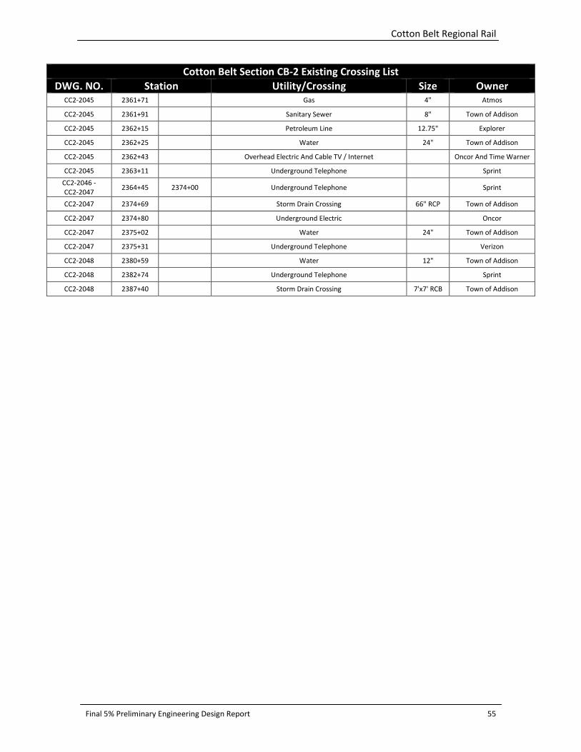
Cotton Belt Regional Rail
Final 5% Preliminary Engineering Design Report 55
Cotton Belt Section CB-2 Existing Crossing List
DWG. NO. Station Utility/Crossing Size Owner
CC2-2045 2361+71 Gas 4" Atmos
CC2-2045 2361+91 Sanitary Sewer 8" Town of Addison
CC2-2045 2362+15 Petroleum Line 12.75" Explorer
CC2-2045 2362+25 Water 24" Town of Addison
CC2-2045 2362+43 Overhead Electric And Cable TV / Internet Oncor And Time Warner
CC2-2045 2363+11 Underground Telephone Sprint
CC2-2046 -
CC2-2047 2364+45 2374+00 Underground Telephone Sprint
CC2-2047 2374+69 Storm Drain Crossing 66" RCP Town of Addison
CC2-2047 2374+80 Underground Electric Oncor
CC2-2047 2375+02 Water 24" Town of Addison
CC2-2047 2375+31 Underground Telephone Verizon
CC2-2048 2380+59 Water 12" Town of Addison
CC2-2048 2382+74 Underground Telephone Sprint
CC2-2048 2387+40 Storm Drain Crossing 7'x7' RCB Town of Addison
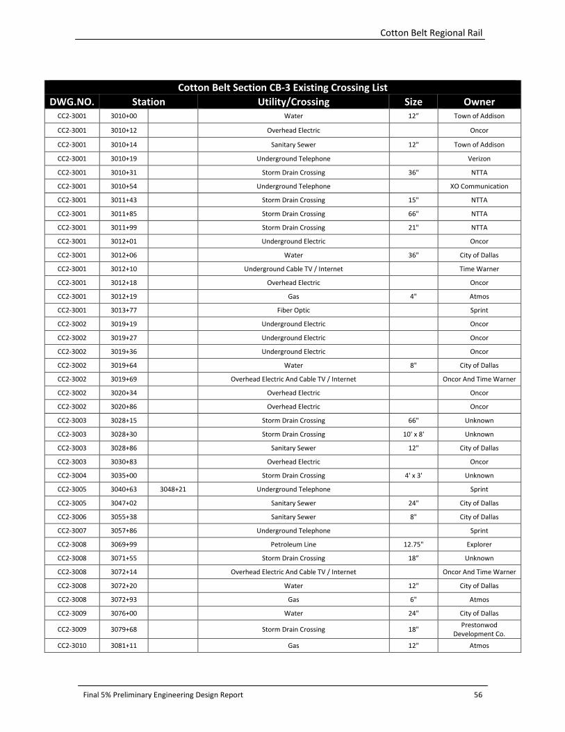
Cotton Belt Regional Rail
Final 5% Preliminary Engineering Design Report 56
Cotton Belt Section CB-3 Existing Crossing List
DWG.NO. Station Utility/Crossing Size Owner
CC2-3001 3010+00 Water 12” Town of Addison
CC2-3001 3010+12
Overhead Electric
Oncor
CC2-3001 3010+14
Sanitary Sewer 12" Town of Addison
CC2-3001 3010+19 Underground Telephone Verizon
CC2-3001 3010+31
Storm Drain Crossing 36" NTTA
CC2-3001 3010+54 Underground Telephone XO Communication
CC2-3001 3011+43
Storm Drain Crossing 15" NTTA
CC2-3001 3011+85
Storm Drain Crossing 66" NTTA
CC2-3001 3011+99
Storm Drain Crossing 21" NTTA
CC2-3001 3012+01
Underground Electric
Oncor
CC2-3001 3012+06
Water 36" City of Dallas
CC2-3001 3012+10
Underground Cable TV / Internet
Time Warner
CC2-3001 3012+18
Overhead Electric
Oncor
CC2-3001 3012+19
Gas 4" Atmos
CC2-3001 3013+77
Fiber Optic
Sprint
CC2-3002 3019+19
Underground Electric
Oncor
CC2-3002 3019+27
Underground Electric
Oncor
CC2-3002 3019+36
Underground Electric
Oncor
CC2-3002 3019+64
Water 8" City of Dallas
CC2-3002 3019+69
Overhead Electric And Cable TV / Internet
Oncor And Time Warner
CC2-3002 3020+34
Overhead Electric
Oncor
CC2-3002 3020+86
Overhead Electric
Oncor
CC2-3003 3028+15
Storm Drain Crossing 66" Unknown
CC2-3003 3028+30
Storm Drain Crossing 10' x 8' Unknown
CC2-3003 3028+86
Sanitary Sewer 12" City of Dallas
CC2-3003 3030+83
Overhead Electric
Oncor
CC2-3004 3035+00
Storm Drain Crossing 4' x 3' Unknown
CC2-3005 3040+63 3048+21 Underground Telephone
Sprint
CC2-3005 3047+02
Sanitary Sewer 24" City of Dallas
CC2-3006 3055+38
Sanitary Sewer 8" City of Dallas
CC2-3007 3057+86
Underground Telephone
Sprint
CC2-3008 3069+99
Petroleum Line 12.75" Explorer
CC2-3008 3071+55
Storm Drain Crossing 18” Unknown
CC2-3008 3072+14
Overhead Electric And Cable TV / Internet
Oncor And Time Warner
CC2-3008 3072+20
Water 12" City of Dallas
CC2-3008 3072+93
Gas 6" Atmos
CC2-3009 3076+00
Water 24" City of Dallas
CC2-3009 3079+68
Storm Drain Crossing 18" Prestonwod
Development Co.
CC2-3010 3081+11
Gas 12" Atmos
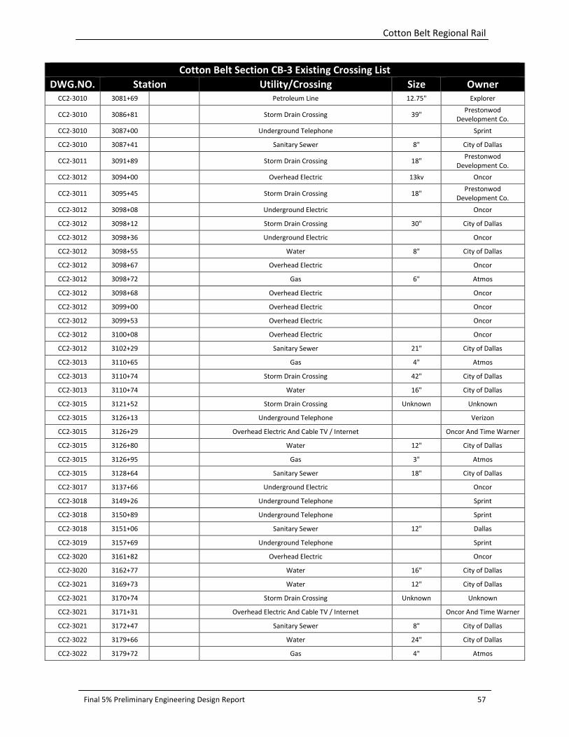
Cotton Belt Regional Rail
Final 5% Preliminary Engineering Design Report 57
Cotton Belt Section CB-3 Existing Crossing List
DWG.NO. Station Utility/Crossing Size Owner
CC2-3010 3081+69
Petroleum Line 12.75" Explorer
CC2-3010 3086+81
Storm Drain Crossing 39" Prestonwod
Development Co.
CC2-3010 3087+00
Underground Telephone
Sprint
CC2-3010 3087+41
Sanitary Sewer 8" City of Dallas
CC2-3011 3091+89
Storm Drain Crossing 18" Prestonwod
Development Co.
CC2-3012 3094+00 Overhead Electric 13kv Oncor
CC2-3011 3095+45
Storm Drain Crossing 18" Prestonwod
Development Co.
CC2-3012 3098+08 Underground Electric Oncor
CC2-3012 3098+12
Storm Drain Crossing 30" City of Dallas
CC2-3012 3098+36
Underground Electric
Oncor
CC2-3012 3098+55
Water 8" City of Dallas
CC2-3012 3098+67
Overhead Electric
Oncor
CC2-3012 3098+72
Gas 6" Atmos
CC2-3012 3098+68 Overhead Electric Oncor
CC2-3012 3099+00
Overhead Electric
Oncor
CC2-3012 3099+53
Overhead Electric
Oncor
CC2-3012 3100+08
Overhead Electric
Oncor
CC2-3012 3102+29
Sanitary Sewer 21" City of Dallas
CC2-3013 3110+65
Gas 4" Atmos
CC2-3013 3110+74
Storm Drain Crossing 42" City of Dallas
CC2-3013 3110+74
Water 16" City of Dallas
CC2-3015 3121+52
Storm Drain Crossing Unknown Unknown
CC2-3015 3126+13
Underground Telephone
Verizon
CC2-3015 3126+29
Overhead Electric And Cable TV / Internet
Oncor And Time Warner
CC2-3015 3126+80
Water 12" City of Dallas
CC2-3015 3126+95
Gas 3" Atmos
CC2-3015 3128+64
Sanitary Sewer 18" City of Dallas
CC2-3017 3137+66
Underground Electric
Oncor
CC2-3018 3149+26
Underground Telephone
Sprint
CC2-3018 3150+89
Underground Telephone
Sprint
CC2-3018 3151+06
Sanitary Sewer 12" Dallas
CC2-3019 3157+69
Underground Telephone
Sprint
CC2-3020 3161+82
Overhead Electric
Oncor
CC2-3020 3162+77
Water 16" City of Dallas
CC2-3021 3169+73
Water 12" City of Dallas
CC2-3021 3170+74
Storm Drain Crossing Unknown Unknown
CC2-3021 3171+31
Overhead Electric And Cable TV / Internet
Oncor And Time Warner
CC2-3021 3172+47
Sanitary Sewer 8" City of Dallas
CC2-3022 3179+66
Water 24" City of Dallas
CC2-3022 3179+72
Gas 4" Atmos
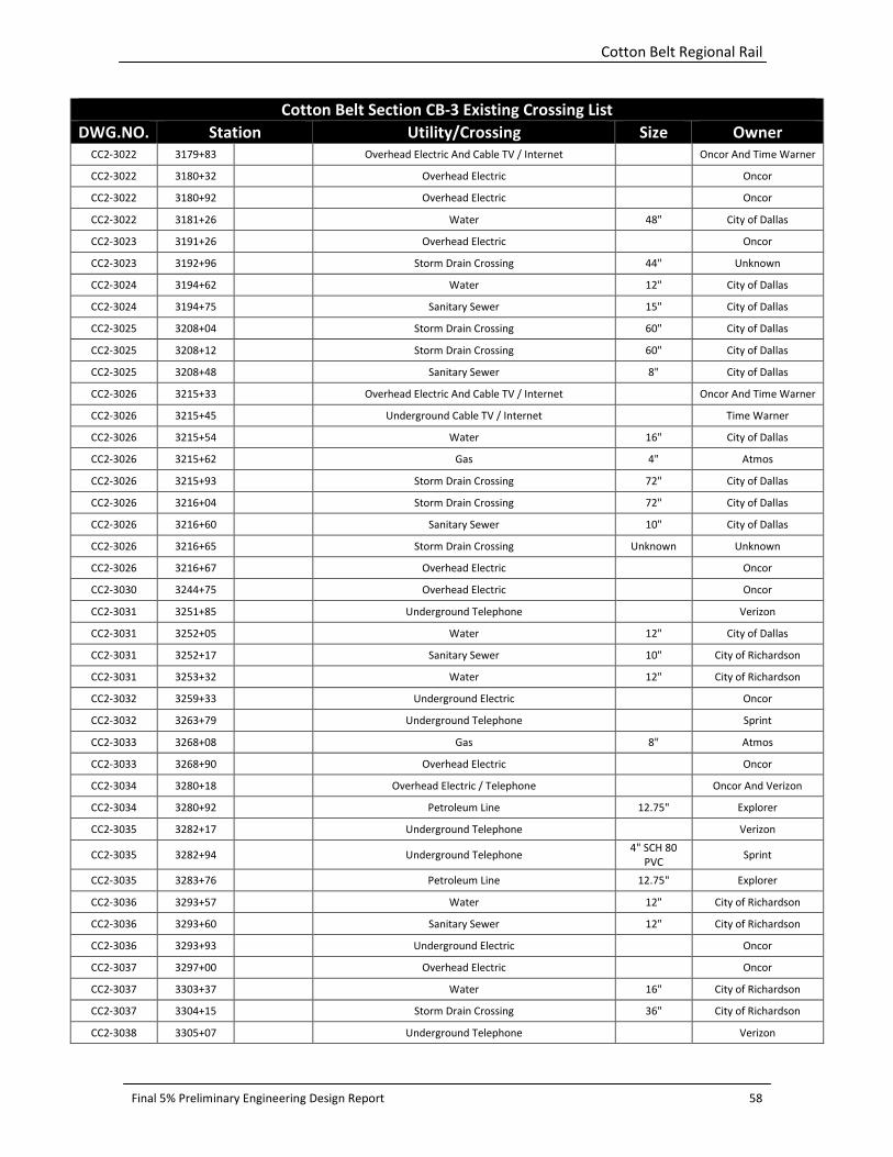
Cotton Belt Regional Rail
Final 5% Preliminary Engineering Design Report 58
Cotton Belt Section CB-3 Existing Crossing List
DWG.NO. Station Utility/Crossing Size Owner
CC2-3022 3179+83
Overhead Electric And Cable TV / Internet
Oncor And Time Warner
CC2-3022 3180+32
Overhead Electric
Oncor
CC2-3022 3180+92
Overhead Electric
Oncor
CC2-3022 3181+26
Water 48" City of Dallas
CC2-3023 3191+26
Overhead Electric
Oncor
CC2-3023 3192+96
Storm Drain Crossing 44" Unknown
CC2-3024 3194+62
Water 12" City of Dallas
CC2-3024 3194+75
Sanitary Sewer 15" City of Dallas
CC2-3025 3208+04
Storm Drain Crossing 60" City of Dallas
CC2-3025 3208+12
Storm Drain Crossing 60" City of Dallas
CC2-3025 3208+48
Sanitary Sewer 8" City of Dallas
CC2-3026 3215+33
Overhead Electric And Cable TV / Internet
Oncor And Time Warner
CC2-3026 3215+45
Underground Cable TV / Internet
Time Warner
CC2-3026 3215+54
Water 16" City of Dallas
CC2-3026 3215+62
Gas 4" Atmos
CC2-3026 3215+93
Storm Drain Crossing 72" City of Dallas
CC2-3026 3216+04
Storm Drain Crossing 72" City of Dallas
CC2-3026 3216+60
Sanitary Sewer 10" City of Dallas
CC2-3026 3216+65
Storm Drain Crossing Unknown Unknown
CC2-3026 3216+67
Overhead Electric
Oncor
CC2-3030 3244+75
Overhead Electric
Oncor
CC2-3031 3251+85
Underground Telephone
Verizon
CC2-3031 3252+05
Water 12" City of Dallas
CC2-3031 3252+17
Sanitary Sewer 10" City of Richardson
CC2-3031 3253+32
Water 12" City of Richardson
CC2-3032 3259+33 Underground Electric Oncor
CC2-3032 3263+79
Underground Telephone
Sprint
CC2-3033 3268+08
Gas 8" Atmos
CC2-3033 3268+90
Overhead Electric
Oncor
CC2-3034 3280+18
Overhead Electric / Telephone
Oncor And Verizon
CC2-3034 3280+92
Petroleum Line 12.75" Explorer
CC2-3035 3282+17
Underground Telephone
Verizon
CC2-3035 3282+94
Underground Telephone 4" SCH 80
PVC Sprint
CC2-3035 3283+76
Petroleum Line 12.75" Explorer
CC2-3036 3293+57
Water 12" City of Richardson
CC2-3036 3293+60
Sanitary Sewer 12" City of Richardson
CC2-3036 3293+93
Underground Electric
Oncor
CC2-3037 3297+00
Overhead Electric
Oncor
CC2-3037 3303+37
Water 16" City of Richardson
CC2-3037 3304+15
Storm Drain Crossing 36" City of Richardson
CC2-3038 3305+07
Underground Telephone
Verizon

Cotton Belt Regional Rail
Final 5% Preliminary Engineering Design Report 59
Cotton Belt Section CB-3 Existing Crossing List
DWG.NO. Station Utility/Crossing Size Owner
CC2-3038 3305+79
Underground Electric
Oncor
CC2-3038 3307+25
Petroleum Line 12.75" Explorer
CC2-3038 3310+11
Storm Drain Crossing 84" Unknown
CC2-3039 -
CC2-3046 3316+30 3375+98 Underground Telephone
Sprint
CC2-3041 3331+97
Sanitary Sewer 10" City of Richardson
CC2-3041 3335+28
Storm Drain Crossing 5' x 3' City of Richardson
CC2-3041 3335+79
Water 12" City of Richardson
CC2-3041 3335+86
Underground Cable TV / Internet
Time Warner
CC2-3041 3335+89
Overhead Electric
Oncor
CC2-3041 3336+26
Water 30" City of Richardson
CC2-3041 3336+60
Gas 6" Atmos
CC2-3041 3336+73
Gas 6" Atmos
CC2-3041 3336+89
Overhead Electric
Oncor
CC2-3041 3336+90
Underground Telephone
Verizon
CC2-3043 3349+31
Sanitary Sewer 12" City of Richardson
CC2-3043 3350+32
Underground Electric
Oncor
CC2-3044 3355+95
Overhead Electric
Oncor
CC2-3044 3359+77
Water 12" City of Richardson
CC2-3044 3361+25
Gas 2" Atmos
CC2-3044 3361+81
Storm Drain Crossing Unknown City of Richardson
CC2-3045 3368+76
Overhead Electric
Oncor
CC2-3046 3369+96
Sanitary Sewer 33" City of Richardson
CC2-3047 3378+50
Storm Drain Crossing 18" City of Richardson
CC2-3047 3381+10
Overhead Electric
Oncor
CC2-3047 3381+35 Petroleum Line 12.75" Explorer
CC2-3047 3381+45
Underground Telephone
Level 3
CC2-3048 3385+00 Underground Telephone Sprint
CC2-3048 3385+75 3389+71 Underground Telephone
Qwest
CC2-3048 3390+77
Underground Telephone
Sprint
CC2-3048 3391+59
Sanitary Sewer 36” City of Plano
CC2-3048 3392+39
Underground Telephone
Level 3
CC2-3049 3400+23
Sanitary Sewer 42" City of Plano
CC2-3050 3408+36
Overhead Electric And Cable TV / Internet
Oncor And Time Warner
CC2-3050 3408+53
Water 18" City of Plano
CC2-3051 3414+07
Storm Drain Crossing 36" TxDOT
CC2-3051 3416+07
Overhead Electric And Cable TV / Internet
Oncor And Time Warner
CC2-3051 3416+53
Water 18" City of Plano
CC2-3052 3417+21
Gas 2" Atmos
CC2-3052 3422+74
Overhead Electric And Cable TV / Internet
Oncor And Time Warner
CC2-3052 3422+90
Water 12" City of Plano
CC2-3052 3423+46
Gas 2" Atmos

Cotton Belt Regional Rail
Final 5% Preliminary Engineering Design Report 60
Cotton Belt Section CB-3 Existing Crossing List
DWG.NO. Station Utility/Crossing Size Owner
CC2-3052 3424+53
Gas 3" Atmos
CC2-3053 3432+90
Sanitary Sewer 8" City of Plano
CC2-3054 3434+22
Storm Drain 18” Unknown
CC2-3054 3434+35
Water 8" City of Plano
CC2-3054 3434+68
Overhead Cable TV / Internet
Time Warner
CC2-3054 3435+02
Overhead Electric
Oncor
CC2-3054 3435+61
Overhead Electric
Oncor
CC2-3054 3436+31 Overhead Electric Oncor
CC2-3054 3439+78
Overhead Electric
Oncor
CC2-3054 3440+04
Overhead Electric
Oncor
CC2-3054 3440+05 Sanitary Sewer 6” City of Plano
CC2-3054 3440+27
Water 8" City of Plano
CC2-3055 -
CC2-3056 3442+18 3452+05 Underground Telephone
Sprint
CC2-3055 3442+24
Underground Telephone
Level 3
CC2-3055 3443+31
Underground Telephone
Level 3
CC2-3055 3443+90
Storm Drain Crossing 18" Unknown
CC2-3055 3445+95
Storm Drain Crossing 60" City of Plano
CC2-3055 3446+06
Gas 8" Atmos
CC2-3055 3448+48
Underground Telephone
Verizon
CC2-3055 3448+65
Water 12" City of Plano
CC2-3056 3449+12
Overhead Electric
Oncor
CC2-3056 3452+36
Storm Drain Crossing 2-18" x
28.5" RCAP City of Plano
CC2-3056 3453+52
Overhead Electric And Cable TV / Internet
Oncor And Time Warner
CC2-3056 3453+66
Water 12" City of Plano
CC2-3056 3453+85
Sanitary Sewer 6" City of Plano
CC2-3056 3454+06
Underground Telephone
Verizon
CC2-3057 3464+82
Underground Cable TV / Internet
Time Warner
CC2-3057 3464+85
Water 12” City of Plano
CC2-3057 3464+94
Underground Telephone
Level 3
CC2-3058 3465+03
Gas 2” Atmos
CC2-3058 3465+17
Overhead Electric
Oncor
CC2-3059 3476+02
Sanitary Sewer 8” City of Plano
CC2-3059 3479+19
Underground Telephone
Sprint
CC2-3061 3494+30
Sanitary Sewer 8” City of Plano
CC2-3061 3494+41
Gas 4” Atmos
CC2-3061 3494+76
Overhead Electric
Oncor
CC2-3062 3501+25
Water 8” City of Plano
CC2-3062 3501+30
Overhead Electric And Cable TV / Internet
Oncor And Time Warner
CC2-3062 3501+35
Underground Telephone
XO Communications
CC2-3062 3502+30
Overhead Electric
Oncor
CC2-3062 3502+40
Gas
Atmos

Cotton Belt Regional Rail
Final 5% Preliminary Engineering Design Report 61
Cotton Belt Section CB-3 Existing Crossing List
DWG.NO. Station Utility/Crossing Size Owner
CC2-3067 3541+17
Water 20” City of Plano
CC2-3069 3553+24
Overhead Electric
Oncor
CC2-3069 3553+32
Overhead Electric
Oncor
CC2-3069 3555+76
Sanitary Sewer 21” City of Plano
CC2-3069 3556+16
Gas 4” Atmos
CC2-3069 3556+20
Water 14” NTMWD
CC2-3069 3556+30
Overhead Electric
Oncor
CC2-3069 3556+95
Overhead Electric
Oncor
CC2-3069 3557+31
Water 8” City of Plano
CC2-3069 3557+41
Overhead Electric
Oncor

Cotton Belt Regional Rail
Final 5% Preliminary Engineering Design Report 62
Appendix B: Cotton Belt Transportation Crossings

Cotton Belt Regional Rail
Final 5% Preliminary Engineering Design Report 63
Appendix B
Cotton Belt Roadway Crossings Inventory
Street Name City/Agency
Existing
Crossing
Type
Functional
Classification
Existing/Proposed
Typical Section
Pavement
Type
Existing
Traffic
Control
Device
Dooley St Grapevine AG Collector 2 Lanes, curb &
gutter Concrete
2 Quad
Gates/Signals
Texan Trail Rd Grapevine GS Major Arterial 6 Lane Divided, Curb Concrete N/A
SH 121 (Int'l
Pkwy) DFW Airport/TxDOT GS Expressway
6 Lane Divided w/
Aux Lanes Asphalt N/A
County Line
Road (Closed) Coppell AG
Not Defined
(Local) Single Lane
Dirt,
Unimproved None
IH 635 Coppell/TXDOT GS Freeway 6 Lane Divided Concrete N/A
S. Royal Ln Coppell AG Principal
Arterial
4 Lane Divided,
Curb/6 Lane Divided,
Curb
Concrete 2 Quad
Gates/Signals
Freeport Pkwy Coppell AG Collector 4 Lane Divided, Curb Concrete 2 Quad
Gates/Signals
Coppell Rd Coppell AG Collector 2 Lane, No Shoulder Asphalt 2 Quad
Gates/Signals
Denton Tap Rd Coppell AG Principal
Arterial 6 Lane Divided, Curb Concrete
2 Quad
Gates/Signals
W Belt Line Rd
(Future) Dallas None
Principal
Arterial
4 Lane Divided,
Curb/6 Lane Divided,
Curb
Concrete N/A
W Belt Line Rd
(Future) Coppell None
Principal
Arterial
4 Lane Divided,
Curb/6 Lane Divided,
Curb
Concrete N/A
Moore Rd Coppell AG Collector 2 Lane w/ Left Turn
Lane, Curb Concrete
2 Quad
Gates/Signals
Mockingbird Ln Coppell AG Collector 2 Lane w/ Left Turn
Lane, Curb Concrete
2 Quad
Gates/Signals
MacArthur Blvd Coppell AG Principal
Arterial 6 Lane Divided, Curb Concrete
2 Quad
Gates/Signals
Fairway Dr Coppell AG Collector 2 Lane w/ Left Turn
Lane, Curb Concrete
2 Quad
Gates/Signals
Driveway -
Industrial
Businesses
Coppell AG None
(Driveway)
2 Way approx 36'
wide Concrete
2 Quad
Gates/Signals
Driveway -
Dallas Pistol
Club
Carrollton GS None
(Driveway)
2 Way approx 12'
wide
Dirt,
Unimproved N/A
President
George Bush
Turnpike
Carrollton/NTTA GS Freeway 6 Lane Divided Concrete N/A
Luna Rd Carrollton AG Arterial 6 Lane Divided w/
Left Turn Lane, Curb Concrete
2 Quad
Gates/Signals
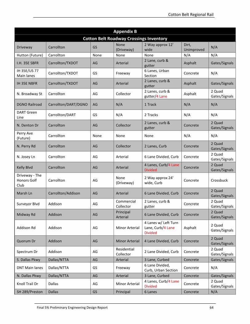
Cotton Belt Regional Rail
Final 5% Preliminary Engineering Design Report 64
Appendix B
Cotton Belt Roadway Crossings Inventory
Driveway Carrollton GS None
(Driveway)
2 Way approx 12'
wide
Dirt,
Unimproved N/A
Hutton (Future) Carrollton None None None N/A N/A
I.H. 35E SBFR Carrollton/TXDOT AG Arterial 2 Lane, curb &
gutter Asphalt Gates/Signals
IH 35E/US 77
Main lanes Carrollton/TXDOT GS Freeway
6 Lanes, Urban
Section Concrete N/A
IH 35E NBFR Carrollton/TXDOT AG Arterial 2 Lanes, curb &
gutter Asphalt Gates/Signals
N. Broadway St Carrollton AG Collector 2 Lanes, curb &
gutter/4 Lane Asphalt
2 Quad
Gates/Signals
DGNO Railroad Carrollton/DART/DGNO AG N/A 1 Track N/A N/A
DART Green
Line Carrollton/DART GS N/A 2 Tracks N/A N/A
N. Denton Dr Carrollton AG Collector 2 Lanes, curb &
gutter Concrete
2 Quad
Gates/Signals
Perry Ave
(Future) Carrollton None None None N/A N/A
N. Perry Rd Carrollton AG Collector 2 Lanes, Curb Concrete 2 Quad
Gates/Signals
N. Josey Ln Carrollton AG Arterial 6 Lane Divided, Curb Concrete 2 Quad
Gates/Signals
Kelly Blvd Carrollton AG Arterial 4 Lanes, Curb/4 Lane
Divided Concrete
2 Quad
Gates/Signals
Driveway - The
Honors Golf
Club
Carrollton AG None
(Driveway)
2 Way approx 24'
wide, Curb Concrete Crossbuck
Marsh Ln Carrollton/Addison AG Arterial 6 Lane Divided, Curb Concrete 2 Quad
Gates/Signals
Surveyor Blvd Addison AG Commercial
Collector
2 Lanes, curb &
gutter Concrete
2 Quad
Gates/Signals
Midway Rd Addison AG Principal
Arterial 6 Lane Divided, Curb Concrete
2 Quad
Gates/Signals
Addison Rd Addison AG Minor Arterial
4 Lanes w/ Left Turn
Lane, Curb/4 Lane
Divided
Asphalt 2 Quad
Gates/Signals
Quorum Dr Addison AG Minor Arterial 4 Lane Divided, Curb Concrete 2 Quad
Gates/Signals
Spectrum Dr Addison AG Residential
Collector 2 Lane Divided, Curb Concrete
2 Quad
Gates/Signals
S. Dallas Pkwy Dallas/NTTA AG Arterial 3 Lane, Curbed Concrete Gates/Signals
DNT Main lanes Dallas/NTTA GS Freeway 6 Lane Divided,
Curb, Urban Section Concrete N/A
N. Dallas Pkwy Dallas/NTTA AG Arterial 3 Lane, Curbed Concrete Gates/Signals
Knoll Trail Dr Dallas AG Minor Arterial 4 Lanes, Curb/4 Lane
Divided Concrete
2 Quad
Gates/Signals
SH 289/Preston Dallas GS Principal 6 Lanes Concrete N/A
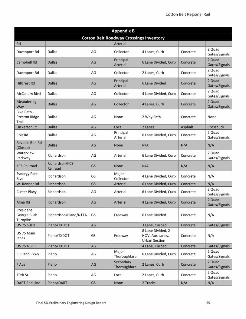
Cotton Belt Regional Rail
Final 5% Preliminary Engineering Design Report 65
Appendix B
Cotton Belt Roadway Crossings Inventory
Rd Arterial
Davenport Rd Dallas AG Collector 4 Lanes, Curb Concrete 2 Quad
Gates/Signals
Campbell Rd Dallas AG Principal
Arterial 6 Lane Divided, Curb Concrete
2 Quad
Gates/Signals
Davenport Rd Dallas AG Collector 2 Lanes, Curb Concrete 2 Quad
Gates/Signals
Hillcrest Rd Dallas AG Principal
Arterial 6 Lane Divided Concrete
2 Quad
Gates/Signals
McCallum Blvd Dallas AG Collector 4 Lane Divided, Curb Concrete 2 Quad
Gates/Signals
Meandering
Way Dallas AG Collector 4 Lanes, Curb Concrete
2 Quad
Gates/Signals
Bike Path -
Preston Ridge
Trail
Dallas AG None 2 Way Path Concrete None
Dickerson St Dallas AG Local 2 Lanes Asphalt Crossbuck
Coit Rd Dallas AG Principal
Arterial 6 Lane Divided, Curb Concrete
2 Quad
Gates/Signals
Revielle Run Rd
(Closed) Dallas AG None N/A N/A N/A
Waterview
Parkway Richardson AG Arterial 6 Lane Divided, Curb Concrete
2 Quad
Gates/Signals
KCS Railroad Richardson/KCS
Railroad GS None N/A N/A N/A
Synergy Park
Blvd Richardson GS
Major
Collector 4 Lane Divided, Curb Concrete N/A
W. Renner Rd Richardson GS Arterial 6 Lane Divided, Curb Concrete N/A
Custer Pkwy Richardson AG Arterial 6 Lane Divided, Curb Concrete 2 Quad
Gates/Signals
Alma Rd Richardson AG Arterial 4 Lane Divided, Curb Concrete 2 Quad
Gates/Signals
President
George Bush
Turnpike
Richardson/Plano/NTTA GS Freeway 6 Lane Divided Concrete N/A
US 75 SBFR Plano/TXDOT AG 3 Lane, Curbed Concrete Gates/Signals
US 75 Main
lanes Plano/TXDOT GS Freeway
8 Lane Divided, 2
HOV, Aux Lanes,
Urban Section
Concrete N/A
US 75 NBFR Plano/TXDOT AG 4 Lane, Curbed Concrete Gates/Signals
E. Plano Pkwy Plano AG Major
Thoroughfare 6 Lane Divided, Curb Concrete
2 Quad
Gates/Signals
F Ave Plano AG Secondary
Thoroughfare 2 Lanes, Curb Concrete
2 Quad
Gates/Signals
10th St Plano AG Local 2 Lanes, Curb Concrete 2 Quad
Gates/Signals
DART Red Line Plano/DART GS None 2 Tracks N/A N/A
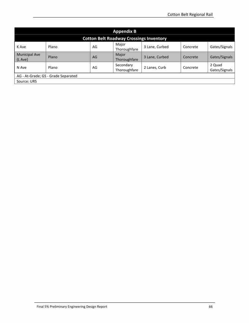
Cotton Belt Regional Rail
Final 5% Preliminary Engineering Design Report 66
Appendix B
Cotton Belt Roadway Crossings Inventory
K Ave Plano AG Major
Thoroughfare 3 Lane, Curbed Concrete Gates/Signals
Municipal Ave
(L Ave) Plano AG
Major
Thoroughfare 3 Lane, Curbed Concrete Gates/Signals
N Ave Plano AG Secondary
Thoroughfare 2 Lanes, Curb Concrete
2 Quad
Gates/Signals
AG - At-Grade; GS - Grade Separated
Source: URS

Cotton Belt Regional Rail
Final 5% Preliminary Engineering Design Report 67
Appendix C: Existing Freight Operations Exhibit

Cotton Belt Regional Rail
Final 5% Preliminary Engineering Design Report 68
Cotton Belt Regional Rail
Final 5% Preliminary Engineering Design Report 69
Appendix D: Traffic Volumes

Cotton Belt Regional Rail
Final 5% Preliminary Engineering Design Report 70
Appendix D
Traffic Volumes
ADT
Roadway Source Date From To Direction Direction
Total
Daily
Total
Royal Lane
Parsons 11/2/2010 RR Tracks RR Tracks N 6,881
Parsons 11/2/2010 RR Tracks RR Tracks S 6,263
NCTCOG(Mobility
2030) 2030
Both 23,380
Freeport Parkway Parsons 11/2/2010 RR Tracks RR Tracks N 6,460
Parsons 11/2/2010 RR Tracks RR Tracks S 5,694
Coppell Road Parsons 11/2/2010 RR Tracks RR Tracks N 1,689
Parsons 11/2/2010 RR Tracks RR Tracks S 1,886
S. Denton Tap Rd
NCTCOG - Unmet 2030 Bethel Rd Belt Line Both 44,571
Saturation Count
Program, TxDOT 2004
Bethel Rd S'western N 15,065
Saturation Count
Program, TxDOT 2004
Bethel Rd S'western S 15,065
City of Coppel 7/21/2009 S of RR Tracks - N 14,703
City of Coppel 7/21/2009
N of RR
Tracks - S 14,647
Parsons 11/2/2010 RR Tracks RR Tracks N 14,524
Parsons 11/2/2010 RR Tracks RR Tracks S 14,922
NCTCOG(Mobility
2030) 2030
Both 43,840
Belt Line Rd
NCTCOG - Unmet 2030
Denton Tap
Rd MacArthur Both 38,669
Saturation Count
Program, TxDOT 2004
Southwestern Moore Rd Both 13,036
City of Coppell 3/28/2005
Denton Tap
Rd Moore Rd Both 15,869
Parsons 11/2/2010
Denton Tap
Rd Moore Rd E 6,737
Parsons 11/2/2010
Denton Tap
Rd Moore Rd W 6,618
NCTCOG(Mobility
2030) 2030
Both 37,970
Belt Line Rd
NCTCOG - Unmet 2030
Denton Tap
Rd MacArthur Both 38,669
Saturation Count
Program, TxDOT 2004
Moore Rd
Mockingbird
Ln Both 14,648
City of Coppell 1/8/2003 Moore Rd MacArthur Both 11,918
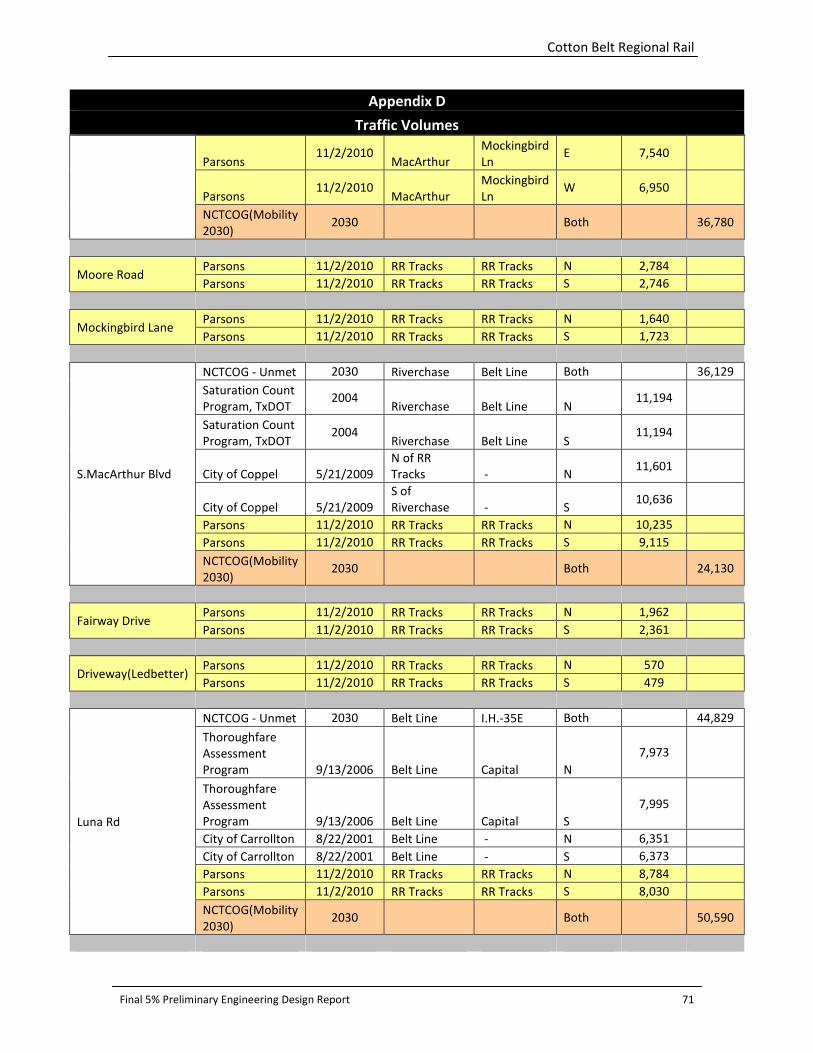
Cotton Belt Regional Rail
Final 5% Preliminary Engineering Design Report 71
Appendix D
Traffic Volumes
Parsons 11/2/2010
MacArthur
Mockingbird
Ln E 7,540
Parsons 11/2/2010
MacArthur
Mockingbird
Ln W 6,950
NCTCOG(Mobility
2030) 2030
Both 36,780
Moore Road Parsons 11/2/2010 RR Tracks RR Tracks N 2,784
Parsons 11/2/2010 RR Tracks RR Tracks S 2,746
Mockingbird Lane Parsons 11/2/2010 RR Tracks RR Tracks N 1,640
Parsons 11/2/2010 RR Tracks RR Tracks S 1,723
S.MacArthur Blvd
NCTCOG - Unmet 2030 Riverchase Belt Line Both 36,129
Saturation Count
Program, TxDOT 2004
Riverchase Belt Line N 11,194
Saturation Count
Program, TxDOT 2004
Riverchase Belt Line S 11,194
City of Coppel 5/21/2009
N of RR
Tracks - N 11,601
City of Coppel 5/21/2009
S of
Riverchase - S 10,636
Parsons 11/2/2010 RR Tracks RR Tracks N 10,235
Parsons 11/2/2010 RR Tracks RR Tracks S 9,115
NCTCOG(Mobility
2030) 2030
Both 24,130
Fairway Drive Parsons 11/2/2010 RR Tracks RR Tracks N 1,962
Parsons 11/2/2010 RR Tracks RR Tracks S 2,361
Driveway(Ledbetter) Parsons 11/2/2010 RR Tracks RR Tracks N 570
Parsons 11/2/2010 RR Tracks RR Tracks S 479
Luna Rd
NCTCOG - Unmet 2030 Belt Line I.H.-35E Both 44,829
Thoroughfare
Assessment
Program 9/13/2006 Belt Line Capital N
7,973
Thoroughfare
Assessment
Program 9/13/2006 Belt Line Capital S
7,995
City of Carrollton 8/22/2001 Belt Line - N 6,351
City of Carrollton 8/22/2001 Belt Line - S 6,373
Parsons 11/2/2010 RR Tracks RR Tracks N 8,784
Parsons 11/2/2010 RR Tracks RR Tracks S 8,030
NCTCOG(Mobility
2030) 2030
Both 50,590

Cotton Belt Regional Rail
Final 5% Preliminary Engineering Design Report 72
Appendix D
Traffic Volumes
IH 35E SBFR Parsons 11/2/2010 RR Tracks RR Tracks S 9,552
IH 35E NBFR Parsons
11/2/2010 RR Tracks RR Tracks
N 9,301
Broadway Street Parsons 11/2/2010 RR Tracks RR Tracks N 2,270
Parsons 11/2/2010 RR Tracks RR Tracks S 2,357
Denton Drive Parsons 11/30/2010 RR Tracks RR Tracks N 1,403
Parsons 11/30/2010 RR Tracks RR Tracks S 1,830
Perry Road Parsons 11/2/2010 RR Tracks RR Tracks N 1,875
Parsons 11/2/2010 RR Tracks RR Tracks S 1,898
N. Josey Ln
NCTCOG - Unmet 2030 RR Tracks RR Tracks Both 37,102
System
Investment
Grade Studies 2/9/2006 Keller Sprngs
Keller
Springs N
13,530
System
Investment
Grade Studies 2/9/2006 Keller Sprngs
Keller
Springs S
15,994
City of Carrollton 6/21/2001 McKamy - N 19,099
City of Carrollton 6/21/2001 McKamy - S 18,823
Parsons 11/2/2010 RR Tracks RR Tracks N 14,934
Parsons 11/2/2010 RR Tracks RR Tracks S 16,691
NCTCOG(Mobility
2030) 2030
Both 36,420
Kelly Boulevard
Parsons 11/2/2010 RR Tracks RR Tracks N 5,736
Parsons 11/2/2010 RR Tracks RR Tracks S 5,542
NCTCOG(Mobility
2030) 2030
Both 24,670
Driveway-Honors
Golf Club
Parsons 11/2/2010 RR Tracks RR Tracks N 61
Parsons 11/2/2010 RR Tracks RR Tracks S 98
Marsh Ln
NCTCOG - Unmet 2030
Research
Keller
Springs Both 38,339
Saturation Count
Program, TxDOT 2004
Keller Springs Arapaho N 19,914
Saturation Count
Program, TxDOT 2004
Keller Springs Arapaho S 19,914
City of Addison 10/27/2009 Arapaho RR Tracks N 16,638
City of Addison 10/27/2009 Arapaho RR Tracks S 16,829
Parsons 11/2/2010 RR Tracks RR Tracks N 17,241
Parsons 11/2/2010 RR Tracks RR Tracks S 17,052

Cotton Belt Regional Rail
Final 5% Preliminary Engineering Design Report 73
Appendix D
Traffic Volumes
NCTCOG(Mobility
2030) 2030
Both 35,050
Surveyor Boulevard Parsons 11/2/2010 RR Tracks RR Tracks N 2,025
Parsons 11/2/2010 RR Tracks RR Tracks S 2,071
Midway Rd
NCTCOG - Unmet 2030 Lindberg Arapaho Both 54,301
Saturation Count
Program, TxDOT 2004
Lindberg Arapaho N 25,441
Saturation Count
Program, TxDOT 2004
Lindberg Arapaho S 25,441
City of Addison 10/27/2009 Belt Line Lindberg N 17,188
City of Addison 10/27/2009 Belt Line Lindberg S 17,085
Parsons 11/30/2010 RR Tracks RR Tracks N 17,783
Parsons 11/30/2010 RR Tracks RR Tracks S 17,761
NCTCOG(Mobility
2030) 2030
Both 61,500
Addison Road
Saturation Count
Program, TxDOT 2004
Lindbergh Arapaho Both 22,073
Parsons 11/2/2010 RR Tracks RR Tracks N 6,137
Parsons 11/2/2010 RR Tracks RR Tracks S 8,799
Quorum Drive Parsons 12/7/2010 RR Tracks RR Tracks N 4,255
Parsons 12/7/2010 RR Tracks RR Tracks S 3,038
Spectrum Drive Parsons 11/2/2010 RR Tracks RR Tracks N 1,685
Parsons 11/2/2010 RR Tracks RR Tracks S 759
DNT SB FR
NCTCOG - Unmet 2030
Keller Springs
Airport
Pkwy S 29,922
System
Investment
Grade Studies 11/3/2005 Airport Pkwy Arapaho S
13,771
Parsons 11/2/2010 RR Tracks RR Tracks S 12,764
DNT NB FR
NCTCOG - Unmet 2030
Bent Tree
Forest
Keller
Springs N 29,727
System
Investment
Grade Studies 11/3/2005 Arapaho
Keller
Springs N
13,039
Parsons 11/2/2010 RR Tracks RR Tracks N 12,144
Knoll Trail Parsons 11/2/2010 RR Tracks RR Tracks N 3,265
Parsons 11/2/2010 RR Tracks RR Tracks S 3,033
Davenport(South) Parsons 12/7/2010 RR Tracks RR Tracks E 2,327

Cotton Belt Regional Rail
Final 5% Preliminary Engineering Design Report 74
Appendix D
Traffic Volumes
Parsons 12/7/2010 RR Tracks RR Tracks W 2,406
Campbell Rd
NCTCOG - Unmet 2030 Keller Sprngs Davenport Both 29,387
Thoroughfare
Assessment
Program 1/30/2007 Keller Sprngs Davenport NW
8,960
Thoroughfare
Assessment
Program 1/30/2007 Keller Sprngs Davenport SE
8,019
City of Dallas 10/29/2001 Keller Sprngs Davenport Both 20,729
Parsons 11/2/2010 RR Tracks RR Tracks E 7,436
Parsons 11/2/2010 RR Tracks RR Tracks W 8,238
NCTCOG(Mobility
2030) 2030
Both 29,020
Davenport(North) Parsons 11/2/2010 RR Tracks RR Tracks N 2,224
Parsons 11/2/2010 RR Tracks RR Tracks S 1,468
Hillcrest Rd
NCTCOG - Unmet 2030 McCallum McKamy Both 23,344
Saturation Count
Program, TxDOT 2004
McCallum McKamy N 8,051
Saturation Count
Program, TxDOT 2004
McCallum McKamy S 8,051
City of Dallas 1/22/2001 McCallum McKamy Both 17,656
Parsons 11/2/2010 RR Tracks RR Tracks N 8,211
Parsons 11/2/2010 RR Tracks RR Tracks S 7,621
NCTCOG(Mobility
2030) 2030
Both 23,540
McCallum
Boulevard
Parsons 11/2/2010 RR Tracks RR Tracks E 1,786
Parsons 11/2/2010 RR Tracks RR Tracks W 2,910
Meandering Way Parsons 11/2/2010 RR Tracks RR Tracks N 1,365
Parsons 11/2/2010 RR Tracks RR Tracks S 1,204
Dickerson Street
Saturation Count
Program, TxDOT 2004
McCallum Frankford Both 1,291
Parsons 11/2/2010 RR Tracks RR Tracks N 596
Parsons 11/2/2010 RR Tracks RR Tracks S 661
Coit Rd
NCTCOG - Unmet 2030 Frankford McCallum Both 53,274
Saturation Count
Program, TxDOT 2004
Frankford McCallum N 23,961
Saturation Count
Program, TxDOT 2004
Frankford McCallum S 23,961
City of Dallas 1/22/2001 Frankford McCallum Both 42,950
Parsons 11/2/2010 RR Tracks RR Tracks N 19,353
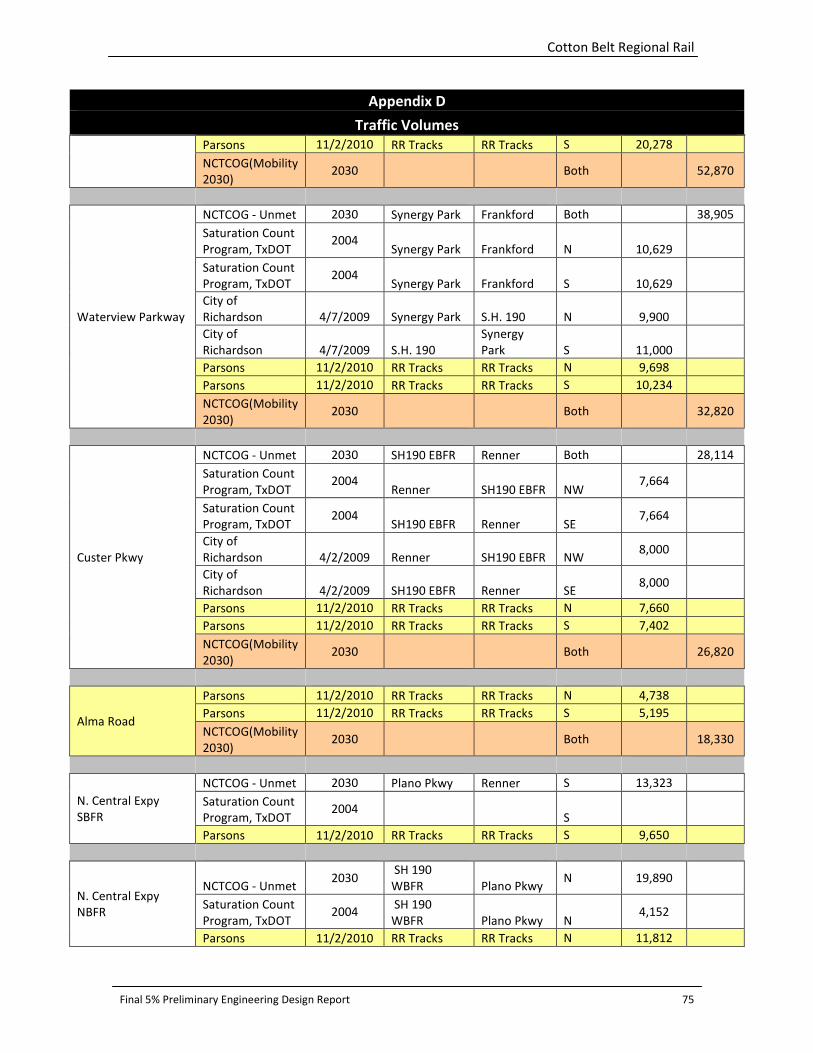
Cotton Belt Regional Rail
Final 5% Preliminary Engineering Design Report 75
Appendix D
Traffic Volumes
Parsons 11/2/2010 RR Tracks RR Tracks S 20,278
NCTCOG(Mobility
2030) 2030
Both 52,870
Waterview Parkway
NCTCOG - Unmet 2030 Synergy Park Frankford Both 38,905
Saturation Count
Program, TxDOT 2004
Synergy Park Frankford N 10,629
Saturation Count
Program, TxDOT 2004
Synergy Park Frankford S 10,629
City of
Richardson 4/7/2009 Synergy Park S.H. 190 N 9,900
City of
Richardson 4/7/2009 S.H. 190
Synergy
Park S 11,000
Parsons 11/2/2010 RR Tracks RR Tracks N 9,698
Parsons 11/2/2010 RR Tracks RR Tracks S 10,234
NCTCOG(Mobility
2030) 2030
Both 32,820
Custer Pkwy
NCTCOG - Unmet 2030 SH190 EBFR Renner Both 28,114
Saturation Count
Program, TxDOT 2004
Renner SH190 EBFR NW 7,664
Saturation Count
Program, TxDOT 2004
SH190 EBFR Renner SE 7,664
City of
Richardson 4/2/2009 Renner SH190 EBFR NW 8,000
City of
Richardson 4/2/2009 SH190 EBFR Renner SE 8,000
Parsons 11/2/2010 RR Tracks RR Tracks N 7,660
Parsons 11/2/2010 RR Tracks RR Tracks S 7,402
NCTCOG(Mobility
2030) 2030
Both 26,820
Alma Road
Parsons 11/2/2010 RR Tracks RR Tracks N 4,738
Parsons 11/2/2010 RR Tracks RR Tracks S 5,195
NCTCOG(Mobility
2030) 2030
Both 18,330
N. Central Expy
SBFR
NCTCOG - Unmet 2030 Plano Pkwy Renner S 13,323
Saturation Count
Program, TxDOT 2004
S
Parsons 11/2/2010 RR Tracks RR Tracks S 9,650
N. Central Expy
NBFR
NCTCOG - Unmet 2030
SH 190
WBFR Plano Pkwy N 19,890
Saturation Count
Program, TxDOT 2004
SH 190
WBFR Plano Pkwy N 4,152
Parsons 11/2/2010 RR Tracks RR Tracks N 11,812

Cotton Belt Regional Rail
Final 5% Preliminary Engineering Design Report 76
Appendix D
Traffic Volumes
Plano Parkway
Parsons 11/2/2010 RR Tracks RR Tracks E 12,076
Parsons 11/2/2010 RR Tracks RR Tracks W 18,775
NCTCOG(Mobility
2030) 2030
Both 38,800
F Avenue
Saturation Count
Program, TxDOT 10/20/2004 RR Tracks RR Tracks Both 2,543
Parsons 11/30/2010 RR Tracks RR Tracks N 888
Parsons 11/30/2010 RR Tracks RR Tracks S 1,130
10th Street
Saturation Count
Program, TxDOT 10/20/2004 RR Tracks RR Tracks S 18,467
Parsons 11/2/2010 RR Tracks RR Tracks E 589
Parsons 11/2/2010 RR Tracks RR Tracks W 921
K Avenue
Saturation Count
Program, TxDOT 10/20/2004 RR Tracks RR Tracks Both 1,180
Parsons 11/2/2010 RR Tracks RR Tracks S 8,528
L Avenue Parsons 11/2/2010 RR Tracks RR Tracks N 7,118
N Avenue
Saturation Count
Program, TxDOT 10/20/2004 RR Tracks RR Tracks Both 2,384
Parsons 11/2/2010 RR Tracks RR Tracks N 777
Parsons 11/2/2010 RR Tracks RR Tracks S 829
NCTCOG(Mobility
2030) 2030
Both 2,230
Jupiter Road
Saturation Count
Program, TxDOT 10/20/2004 RR Tracks RR Tracks N 14,434
Parsons 11/2/2010 RR Tracks RR Tracks N 11,896
Parsons 11/2/2010 RR Tracks RR Tracks S 12,540
NCTCOG(Mobility
2030) 2030
Both 37,780
Shiloh Road
Saturation Count
Program, TxDOT 10/20/2004 RR Tracks RR Tracks N 6,581
Parsons 11/2/2010 RR Tracks RR Tracks N 5,692
Parsons 11/2/2010 RR Tracks RR Tracks S 5,688
NCTCOG(Mobility
2030) 2030
Both 46,720

Cotton Belt Regional Rail
Final 5% Preliminary Engineering Design Report 77
Appendix E: Bridge Structures List
Cotton Belt Regional Rail
Final 5% Preliminary Engineering Design Report 78
Cotton Belt Regional Rail
Final 5% Preliminary Engineering Design Report 79
Appendix F: Table of Supporting Engineering Documents

Cotton Belt Regional Rail
Final 5% Preliminary Engineering Design Report 80
Appendix F: TO 4 and TO 42 Cotton Belt Supporting Engineering Documents:
Name of File Date Submitted to DART Status
DRAFT – Design Criteria Manual
(Volume 1 of 2)
July 2010 (revised
January 2011)
Submitted on July
14, 2010
Draft PDF
CADD File Management Manual September 2010 Draft PDF and MS Word
DRAFT – Existing Freight Operations
TM
October 11, 2010 Draft MS Word
Systems Integration TM November 24, 2010 Draft MS Word
Safety and Security Certification (SSCP)
TM
November 24, 2010 Draft MS Word
Existing Track Assessment Report February 28, 2011 Version 1.2 Draft PDF
Existing Signals Assessment Report February 28, 2011 Draft; PDF
Design Criteria Volume 2 February 28, 2011 Version 1.1. Draft PDF
Systems Preliminary Engineering –
Sketches Report
March 17 & 18,
2011
Draft; PDF Version 1.1
Grade Separation Analysis Report August 2011 Version 3.0 Draft PDF
has some track changes
Final Preliminary Engineering 5%
Design Report
August 2013
Final Preliminary Engineering 5%
Design Cost Estimate
August 2013
Final Preliminary Engineering 5%
Design Station Layouts
August 2013