corrosion basics specialty problems · corrosion - best practices • adopt a corrosion management...
TRANSCRIPT
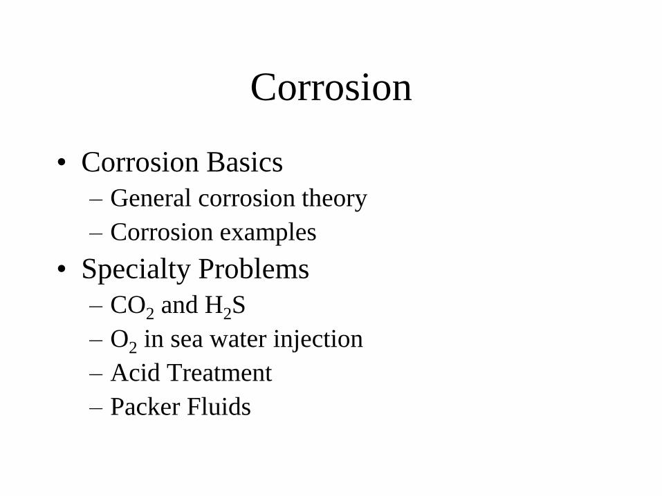
Corrosion
• Corrosion Basics
– General corrosion theory
– Corrosion examples
• Specialty Problems
– CO2 and H2S
– O2 in sea water injection
– Acid Treatment
– Packer Fluids
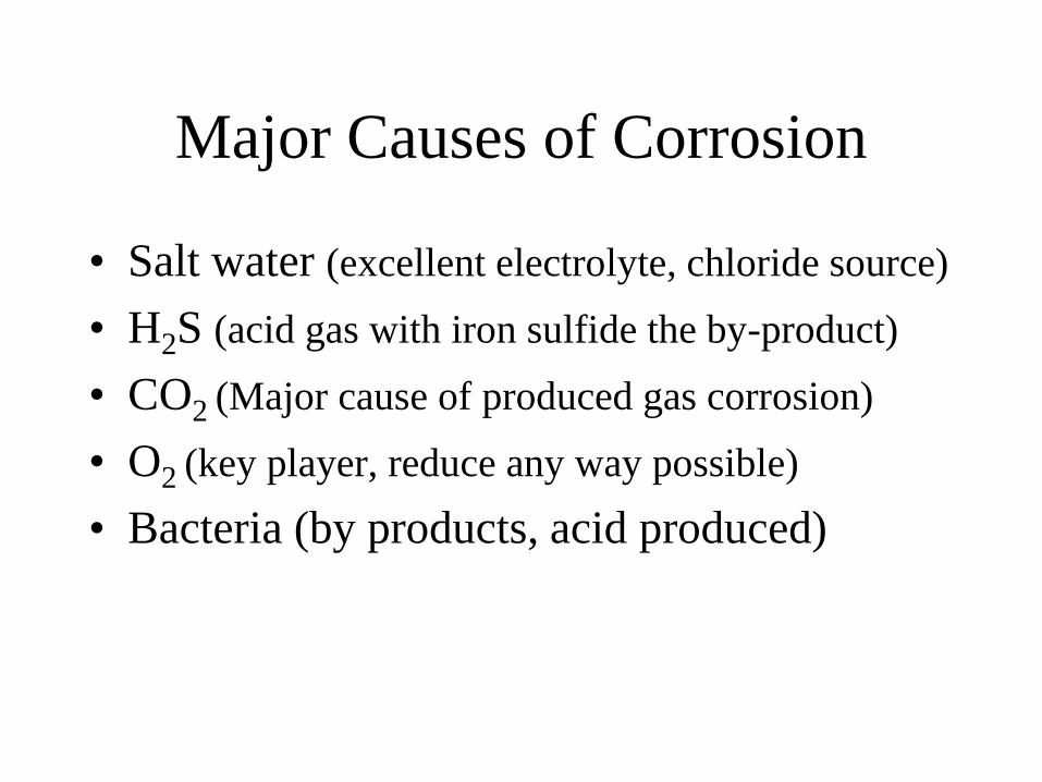
Major Causes of Corrosion
• Salt water (excellent electrolyte, chloride source)
• H2S (acid gas with iron sulfide the by-product)
• CO2 (Major cause of produced gas corrosion)
• O2 (key player, reduce any way possible)
• Bacteria (by products, acid produced)
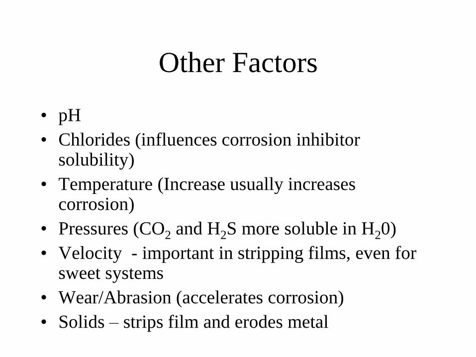
Other Factors
• pH
• Chlorides (influences corrosion inhibitor solubility)
• Temperature (Increase usually increases corrosion)
• Pressures (CO2 and H2S more soluble in H20)
• Velocity - important in stripping films, even for sweet systems
• Wear/Abrasion (accelerates corrosion)
• Solids – strips film and erodes metal
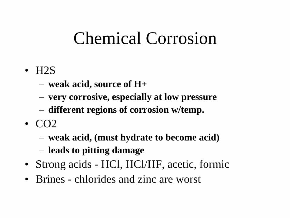
Chemical Corrosion
• H2S
– weak acid, source of H+
– very corrosive, especially at low pressure
– different regions of corrosion w/temp.
• CO2
– weak acid, (must hydrate to become acid)
– leads to pitting damage
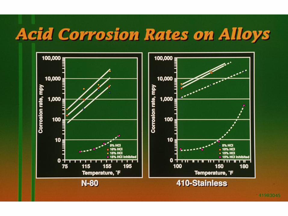
• Strong acids - HCl, HCl/HF, acetic, formic
• Brines - chlorides and zinc are worst
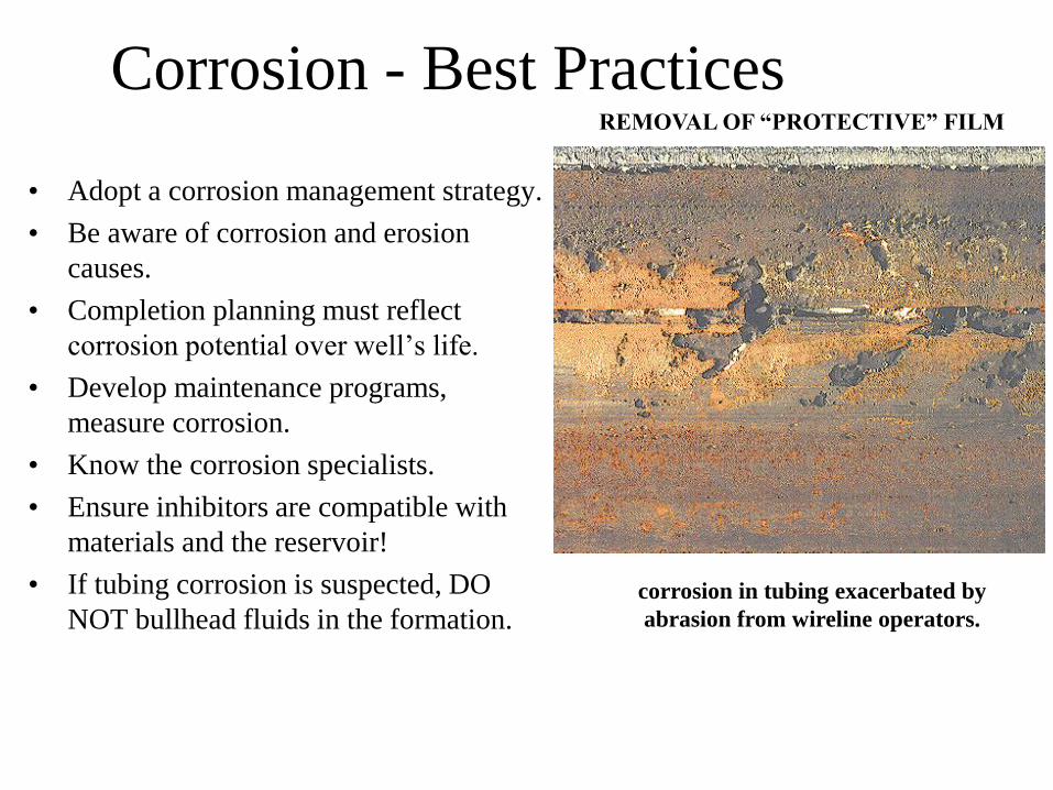
corrosion in tubing exacerbated by
abrasion from wireline operators.
REMOVAL OF “PROTECTIVE” FILM
Corrosion - Best Practices
• Adopt a corrosion management strategy.
• Be aware of corrosion and erosion
causes.
• Completion planning must reflect
corrosion potential over well’s life.
• Develop maintenance programs,
measure corrosion.
• Know the corrosion specialists.
• Ensure inhibitors are compatible with
materials and the reservoir!
• If tubing corrosion is suspected, DO
NOT bullhead fluids in the formation.

1970’s Industry Study of Failures
Method % of Failures
Corrosion (all types) 33%
Fatigue 18%
Brittle Fracture 9%
Mechanical Damage 14%
Fab./Welding Defects 16%
Other 10%
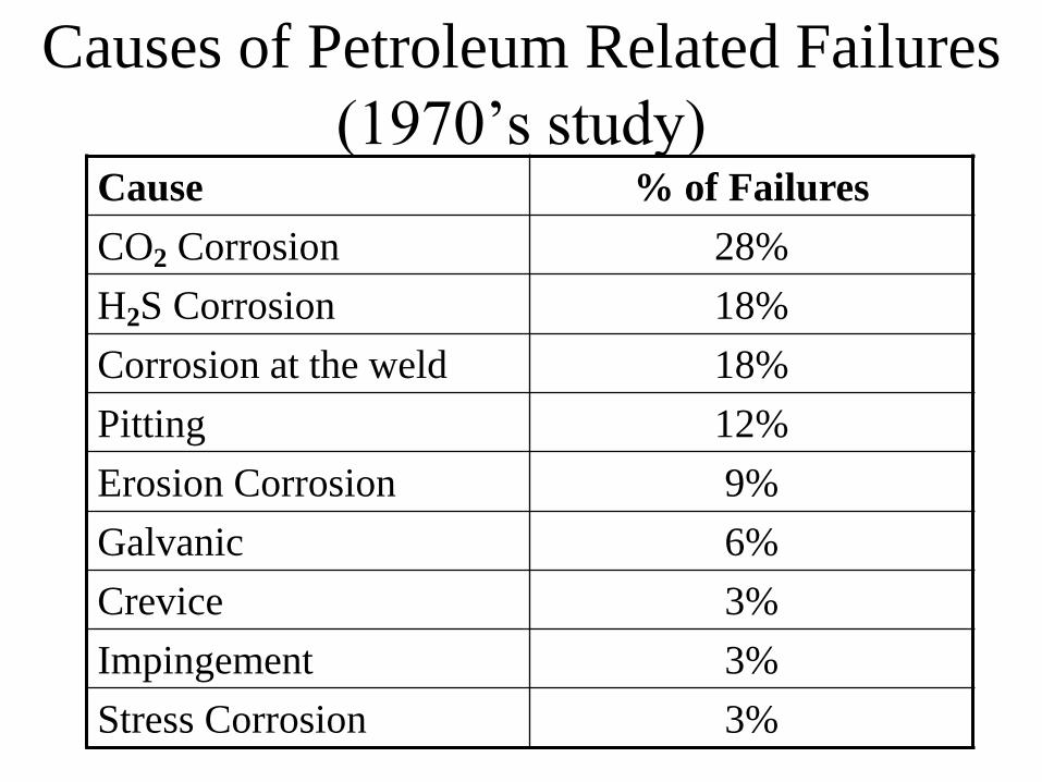
Causes of Petroleum Related Failures
(1970’s study) Cause % of Failures
CO2 Corrosion 28%
H2S Corrosion 18%
Corrosion at the weld 18%
Pitting 12%
Erosion Corrosion 9%
Galvanic 6%
Crevice 3%
Impingement 3%
Stress Corrosion 3%
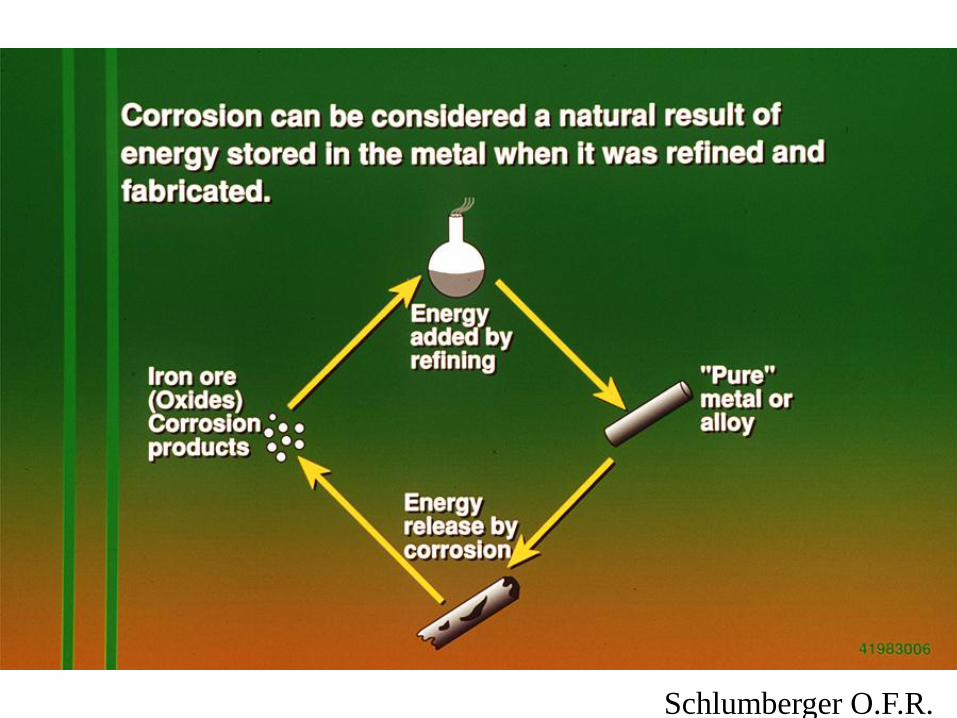
Schlumberger O.F.R.
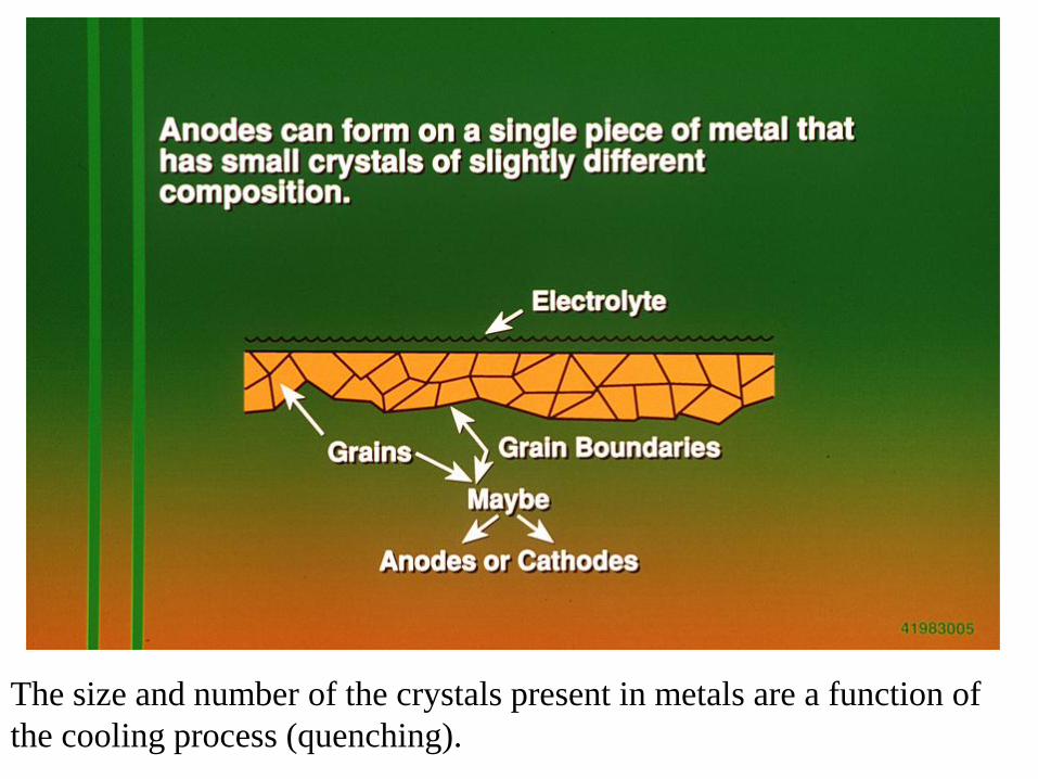
The size and number of the crystals present in metals are a function of
the cooling process (quenching).
Corrosion Types
• Galvanic – a potential difference between dissimilar metals in
contact creates a current flow. This may also occur in some metals at the grain boundaries.
• Crevice Corrosion – Intensive localized electrochemical
corrosion occurs within crevices when in contact with a corrosive fluid. Will accelerate after start.
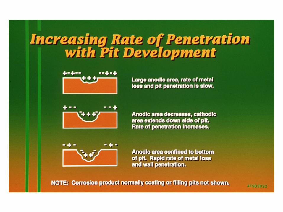
• Pitting – Extremely localized attack that results in holes in the
metal. Will accelerate after start.
• Stress Corrosion – Occurs in metal that is subject to both stress
and a corrosive environment. May start at a “stress riser” like a wrench mark or packer slip mark.
Corrosion Types
• Erosion Corrosion – Passage of fluid at high velocity may
remove the thin, protective oxide film that protects exposed metal
surface.
• Hydrogen Sulfide Corrosion – H2S gas a water creates an
acid gas environment resulting in FeSx and hydrogen.
• Hydrogen Embrittlement – Atomic hydrogen diffuses into
the grain boundary of the metal, generating trapped larger molecules of
hydrogen molecules, resulting in metal embrittlement.
• Hydrogen Corrosion – Hydrogen blistering, hydrogen
embrittlement, decarburization and hydrogen attack..
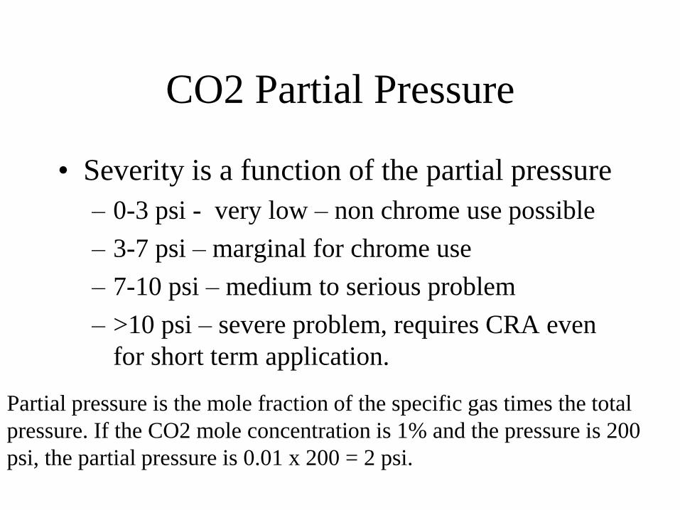
CO2 Partial Pressure
• Severity is a function of the partial pressure
– 0-3 psi - very low – non chrome use possible
– 3-7 psi – marginal for chrome use
– 7-10 psi – medium to serious problem
– >10 psi – severe problem, requires CRA even
for short term application.
Partial pressure is the mole fraction of the specific gas times the total
pressure. If the CO2 mole concentration is 1% and the pressure is 200
psi, the partial pressure is 0.01 x 200 = 2 psi.
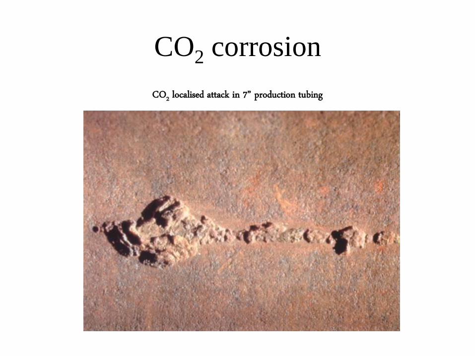
CO2 corrosion
CO2 localised attack in 7” production tubing

The corrosion
rate of CO2 is a
function of
partial pressure,
temperature,
chloride
presence of
water and the
type of material.
Corrosion rate in
MPY – mills per
year is a standard
method of
expression, but not a
good way to express
corrosion where
pitting is the major
failure.
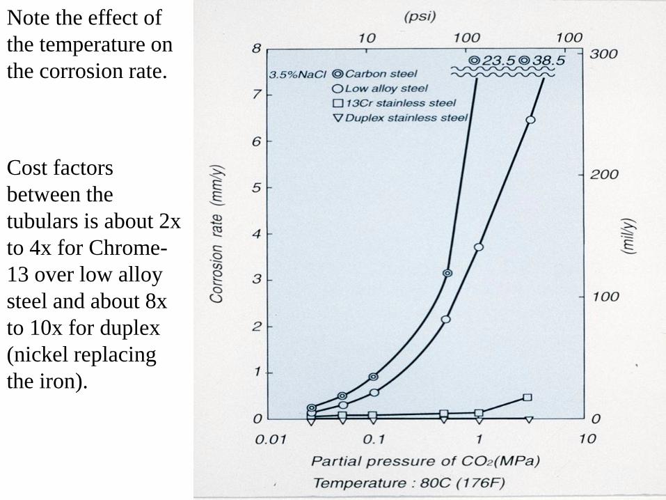
Note the effect of
the temperature on
the corrosion rate.
Cost factors
between the
tubulars is about 2x
to 4x for Chrome-
13 over low alloy
steel and about 8x
to 10x for duplex
(nickel replacing
the iron).
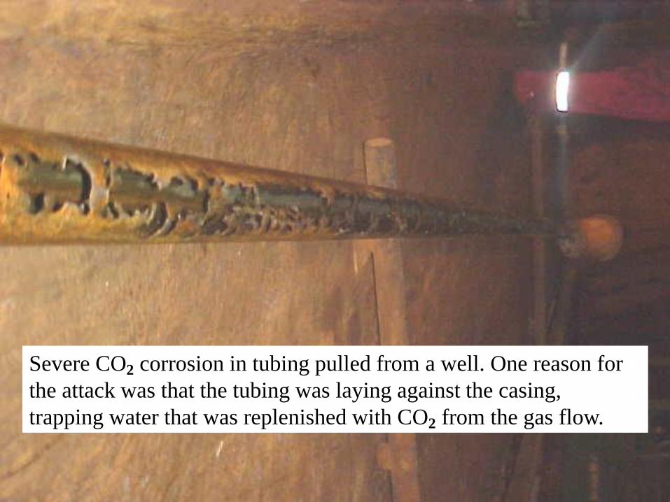
Severe CO2 corrosion in tubing pulled from a well. One reason for
the attack was that the tubing was laying against the casing,
trapping water that was replenished with CO2 from the gas flow.
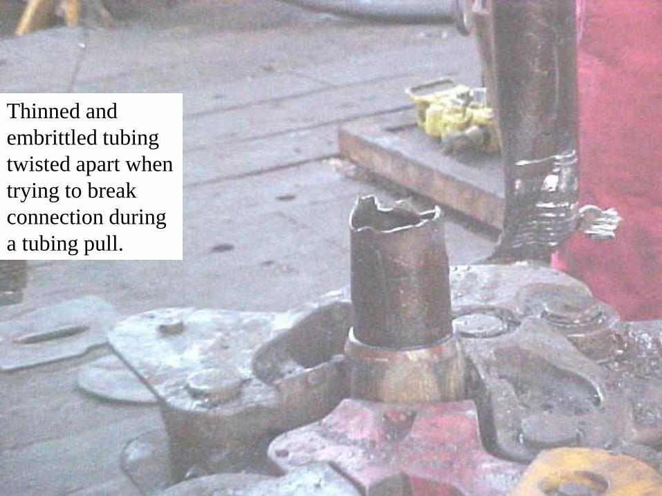
Thinned and
embrittled tubing
twisted apart when
trying to break
connection during
a tubing pull.
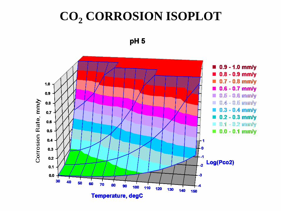
CO2 CORROSION ISOPLOT
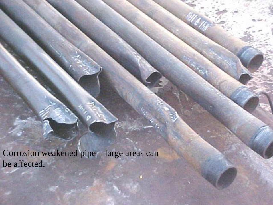
Corrosion weakened pipe – large areas can
be affected.
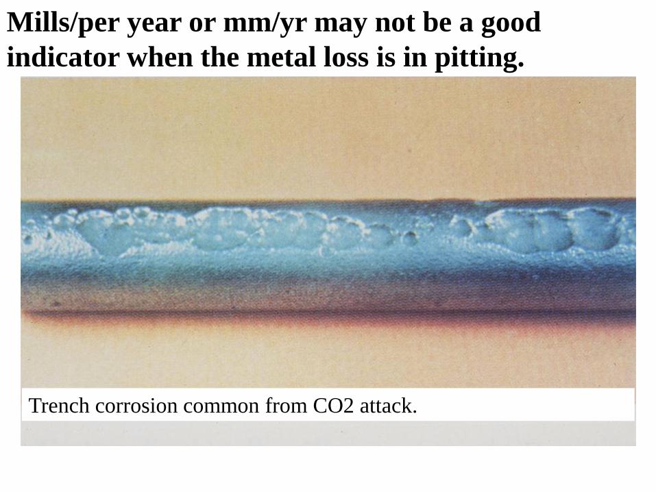
Trench corrosion common from CO2 attack.
Mills/per year or mm/yr may not be a good
indicator when the metal loss is in pitting.
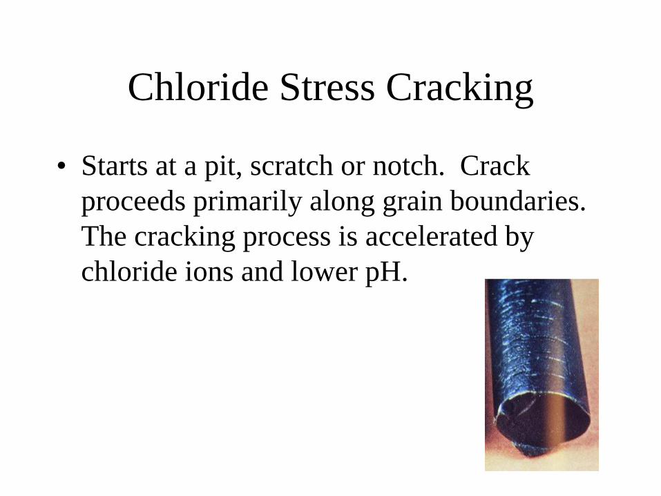
Chloride Stress Cracking
• Starts at a pit, scratch or notch. Crack
proceeds primarily along grain boundaries.
The cracking process is accelerated by
chloride ions and lower pH.

Stress Sulfide Corrosion
• Occurs when metal is in tension and
exposed to H2S and water.
• Generates atomic hydrogen. Hydrogen
moves between grains of the metal.
Reduces metal ductility.
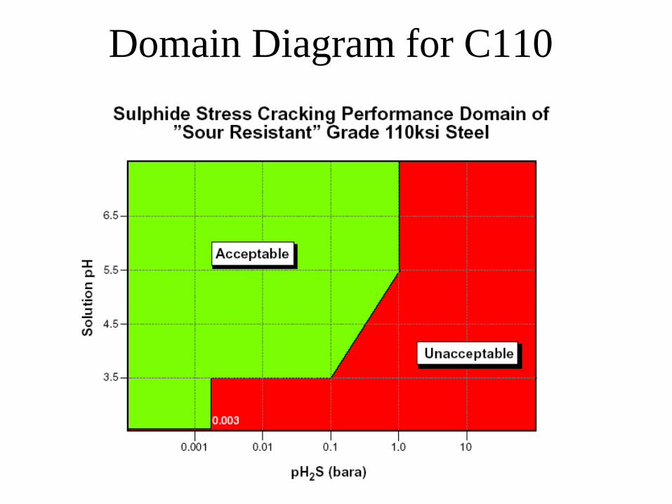
Domain Diagram for C110
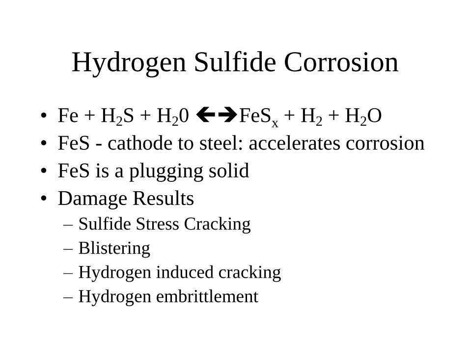
Hydrogen Sulfide Corrosion
• Fe + H2S + H20 FeSx + H2 + H2O
• FeS - cathode to steel: accelerates corrosion
• FeS is a plugging solid
• Damage Results
– Sulfide Stress Cracking
– Blistering
– Hydrogen induced cracking
– Hydrogen embrittlement
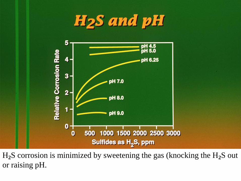
H2S corrosion is minimized by sweetening the gas (knocking the H2S out
or raising pH.
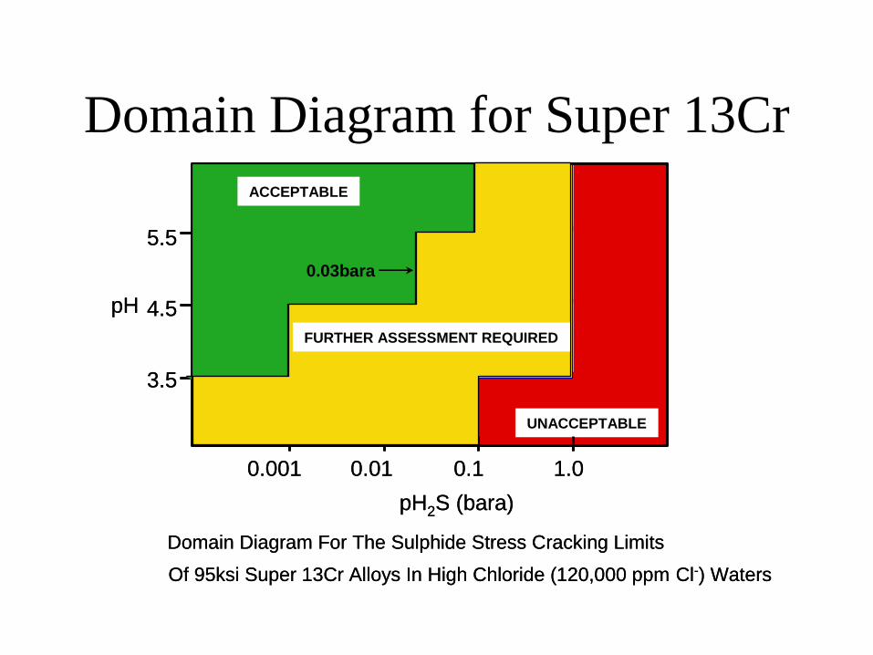
Domain Diagram for Super 13Cr
pH
3.5
4.5
5.5
0.001 0.01 0.1 1.0
pH2S (bara)
Domain Diagram For The Sulphide Stress Cracking Limits
Of 95ksi Super 13Cr Alloys In High Chloride (120,000 ppm Cl-) Waters
UNACCEPTABLE
ACCEPTABLE
0.03bara
FURTHER ASSESSMENT REQUIRED
pH
3.5
4.5
5.5
0.001 0.01 0.1 1.0
pH2S (bara)
Domain Diagram For The Sulphide Stress Cracking Limits
Of 95ksi Super 13Cr Alloys In High Chloride (120,000 ppm Cl-) Waters
UNACCEPTABLE
ACCEPTABLE
0.03bara
FURTHER ASSESSMENT REQUIRED
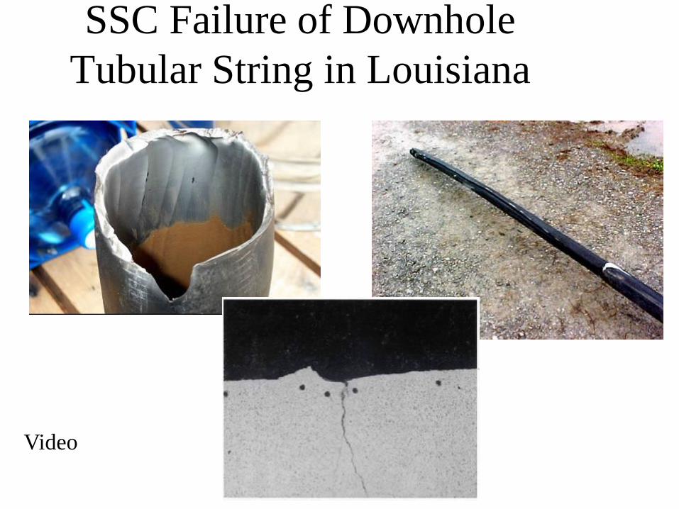
SSC Failure of Downhole
Tubular String in Louisiana
Video
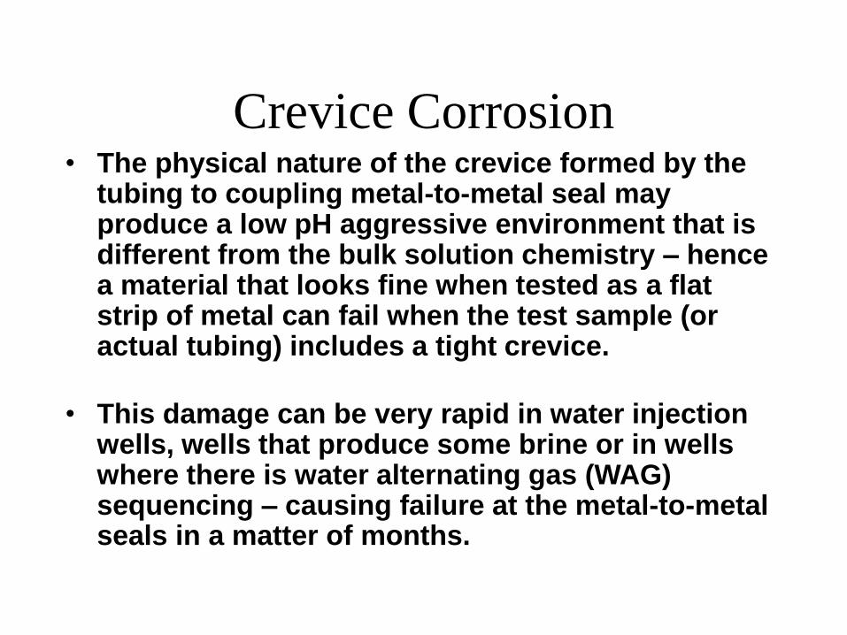
Crevice Corrosion • The physical nature of the crevice formed by the
tubing to coupling metal-to-metal seal may produce a low pH aggressive environment that is different from the bulk solution chemistry – hence a material that looks fine when tested as a flat strip of metal can fail when the test sample (or actual tubing) includes a tight crevice.
• This damage can be very rapid in water injection wells, wells that produce some brine or in wells where there is water alternating gas (WAG) sequencing – causing failure at the metal-to-metal seals in a matter of months.

Crevice Corrosion Note the seal crevice corrosion – this caused a leak to the annulus.
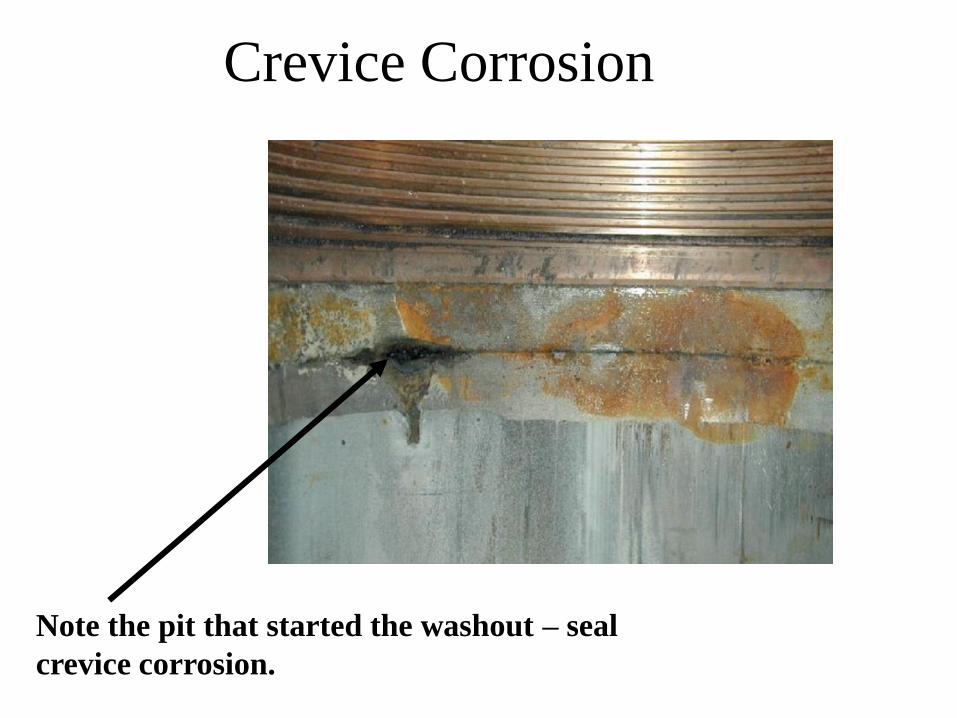
Crevice Corrosion
Note the pit that started the washout – seal
crevice corrosion.
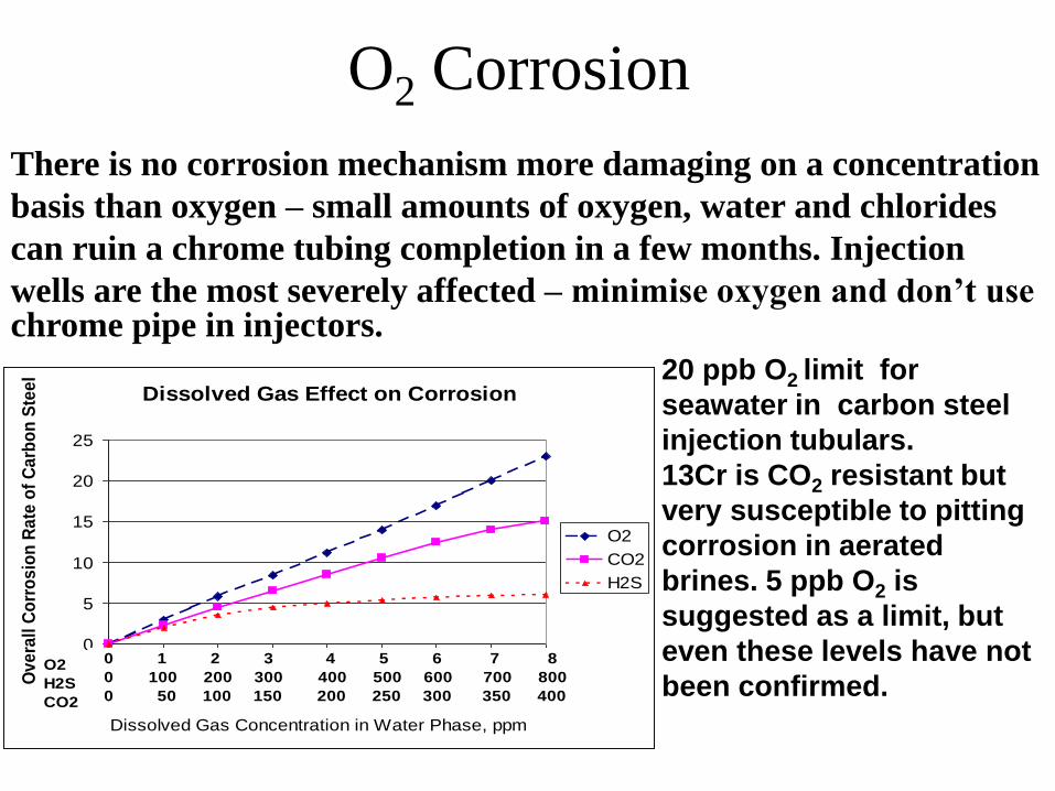
O2 Corrosion
Dissolved Gas Effect on Corrosion
0
5
10
15
20
25
0 1 2 3 4 5 6 7 8
Ov
era
ll C
orr
os
ion
Ra
te o
f C
arb
on
Ste
el
O2
CO2
H2S
Dissolved Gas Concentration in Water Phase, ppm
0 1 2 3 4 5 6 7 8
0 100 200 300 400 500 600 700 800
0 50 100 150 200 250 300 350 400
O2
H2S
CO2
There is no corrosion mechanism more damaging on a concentration
basis than oxygen – small amounts of oxygen, water and chlorides
can ruin a chrome tubing completion in a few months. Injection
wells are the most severely affected – minimise oxygen and don’t use chrome pipe in injectors.
20 ppb O2 limit for
seawater in carbon steel
injection tubulars.
13Cr is CO2 resistant but
very susceptible to pitting
corrosion in aerated
brines. 5 ppb O2 is
suggested as a limit, but
even these levels have not
been confirmed.
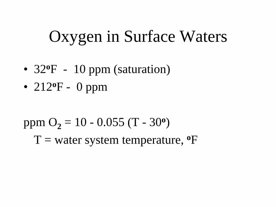
Oxygen in Surface Waters
• 32oF - 10 ppm (saturation)
• 212oF - 0 ppm
ppm O2 = 10 - 0.055 (T - 30o)
T = water system temperature, oF
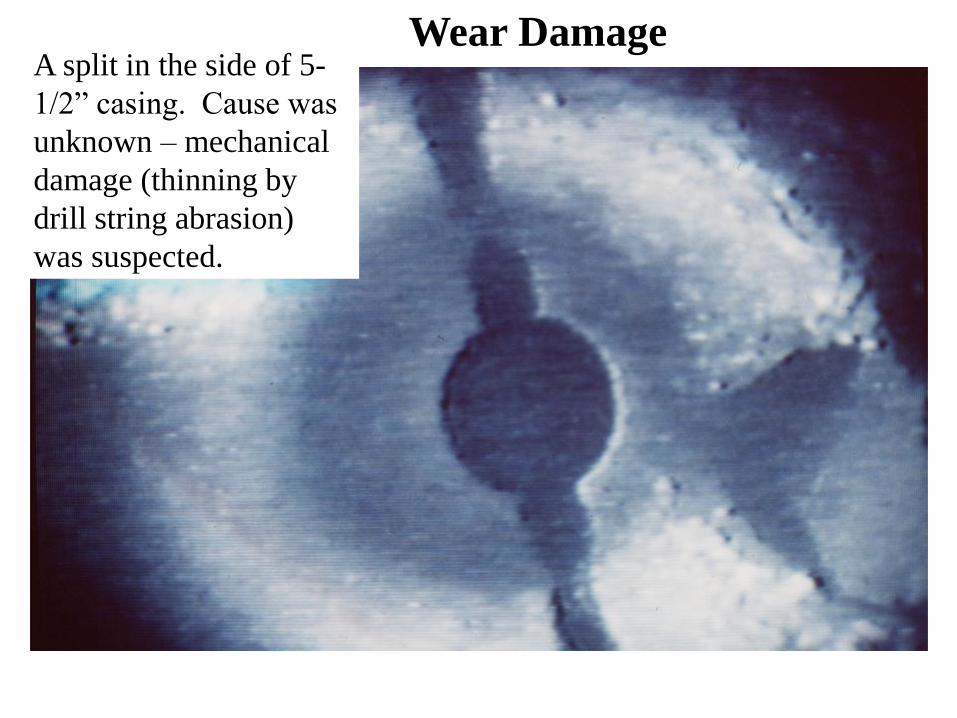
A split in the side of 5-
1/2” casing. Cause was
unknown – mechanical
damage (thinning by
drill string abrasion)
was suspected.
Wear Damage
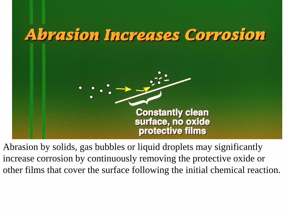
Abrasion by solids, gas bubbles or liquid droplets may significantly
increase corrosion by continuously removing the protective oxide or
other films that cover the surface following the initial chemical reaction.

Most graphs do not show the effect of too low a velocity on the corrosion
rate. When the surface is not swept clean, biofilms can develop or the
surface liquid layer may saturate with CO2 or other gas, increasing
corrosion. Minimum rates are about 3.5 ft/sec for clean fluids.
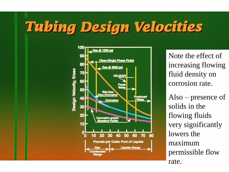
Note the effect of
increasing flowing
fluid density on
corrosion rate.
Also – presence of
solids in the
flowing fluids
very significantly
lowers the
maximum
permissible flow
rate.
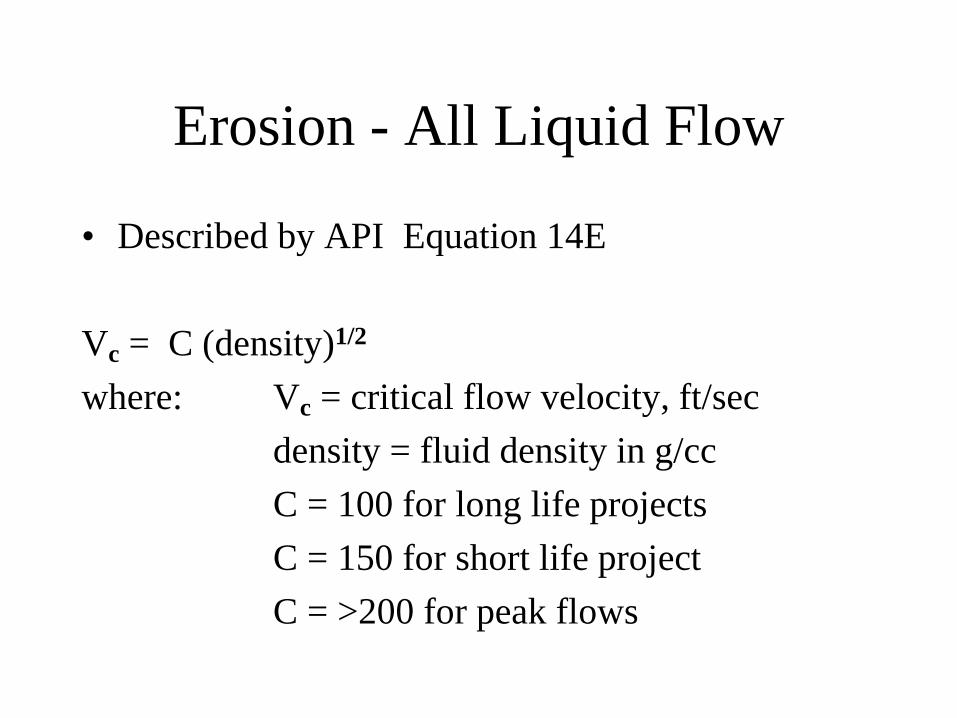
Erosion - All Liquid Flow
• Described by API Equation 14E
Vc = C (density)1/2
where: Vc = critical flow velocity, ft/sec
density = fluid density in g/cc
C = 100 for long life projects
C = 150 for short life project
C = >200 for peak flows
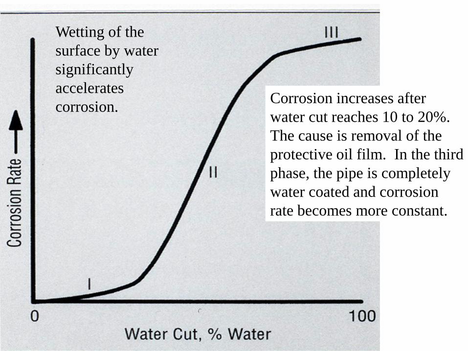
Corrosion increases after
water cut reaches 10 to 20%.
The cause is removal of the
protective oil film. In the third
phase, the pipe is completely
water coated and corrosion
rate becomes more constant.
Wetting of the
surface by water
significantly
accelerates
corrosion.

Top, Left: Chrome pipe after acidizing with the
proper inhibitor and inhibitor intensifier.
Bottom, Left: Chrome pipe after acidizing with
a marginal inhibitor.
Bottom, Right: Chrome pipe after acidizing
without an inhibitor.
15% HCl, 2 hour exposure
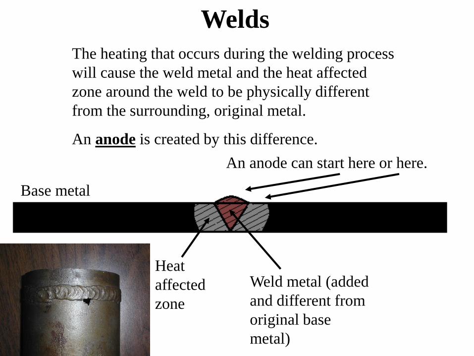
Welds
The heating that occurs during the welding process
will cause the weld metal and the heat affected
zone around the weld to be physically different
from the surrounding, original metal.
An anode is created by this difference.
An anode can start here or here.
Heat
affected
zone
Weld metal (added
and different from
original base
metal)
Base metal
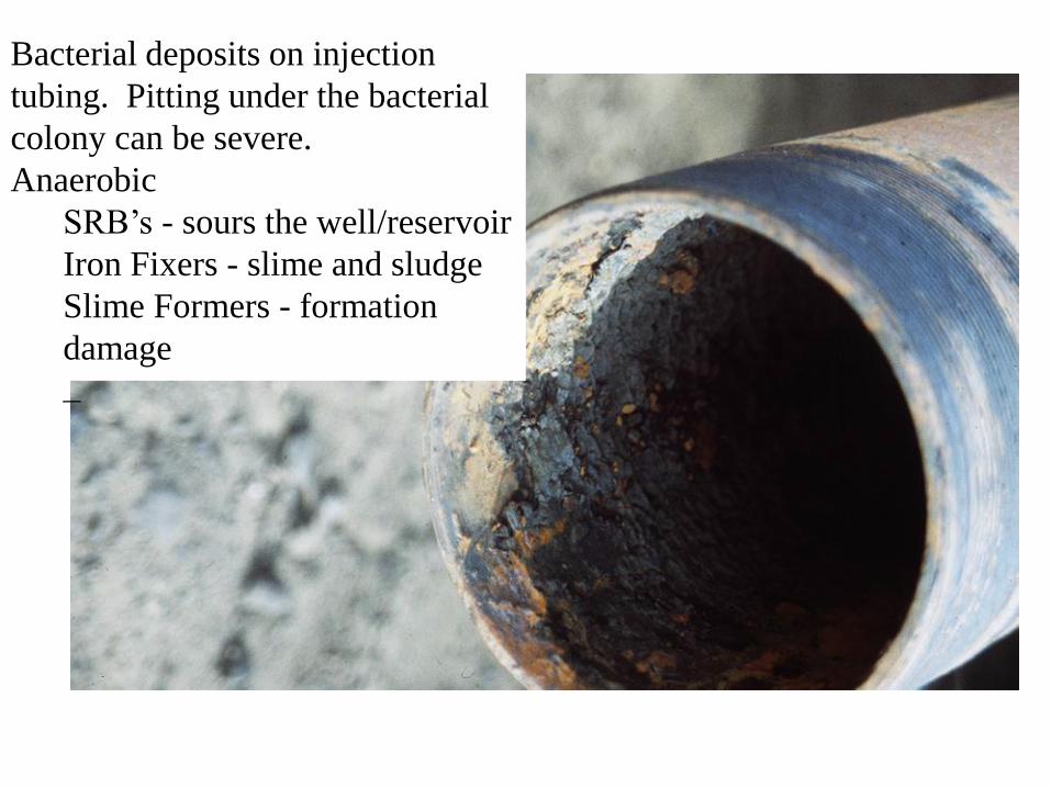
Bacterial deposits on injection
tubing. Pitting under the bacterial
colony can be severe.
Anaerobic
SRB’s - sours the well/reservoir
Iron Fixers - slime and sludge
Slime Formers - formation
damage
–
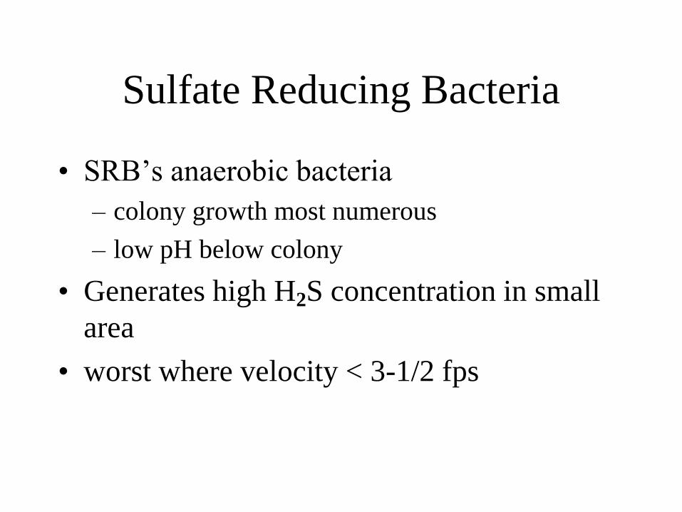
Sulfate Reducing Bacteria
• SRB’s anaerobic bacteria
– colony growth most numerous
– low pH below colony
• Generates high H2S concentration in small
area
• worst where velocity < 3-1/2 fps
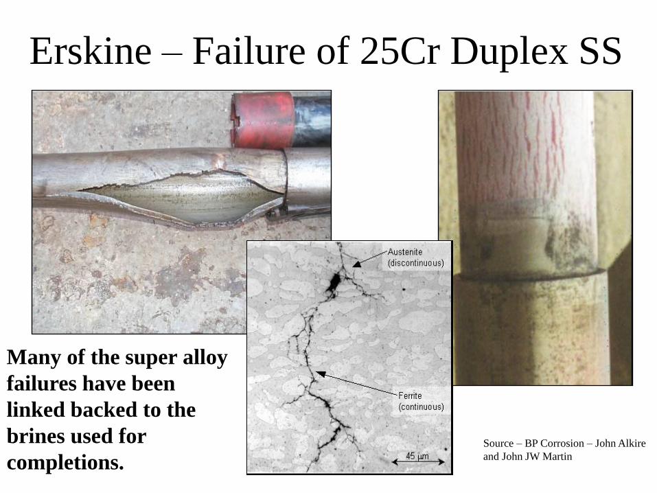
Erskine – Failure of 25Cr Duplex SS
Source – BP Corrosion – John Alkire
and John JW Martin
Many of the super alloy
failures have been
linked backed to the
brines used for
completions.

High Island – Failure of 13Cr
Alloy
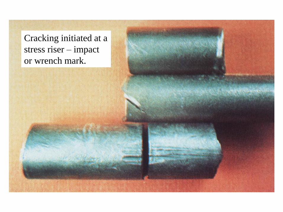
Cracking initiated at a
stress riser – impact
or wrench mark.

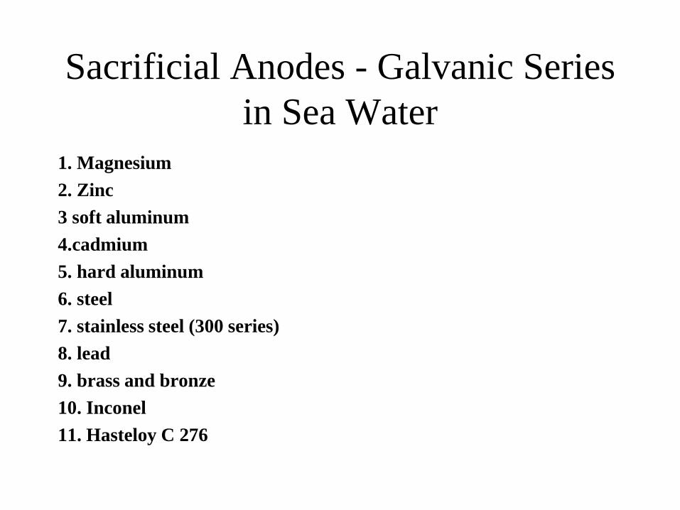
Sacrificial Anodes - Galvanic Series
in Sea Water
1. Magnesium
2. Zinc
3 soft aluminum
4.cadmium
5. hard aluminum
6. steel
7. stainless steel (300 series)
8. lead
9. brass and bronze
10. Inconel
11. Hasteloy C 276

Sacrificial anode (magnesium) from an offshore platform. This was a
round bar stock anode.
Controlling Corrosion
1. Maintain high pH
2. Control gas breakout
3. Use passive metals
4. Remove Oxygen
5. Control velocities
6. Lower chlorides
7. Bacteria control
8. Acid/brine use considerations and alternatives
9. Liquid removal
10. Inhibitor injection
11. coatings
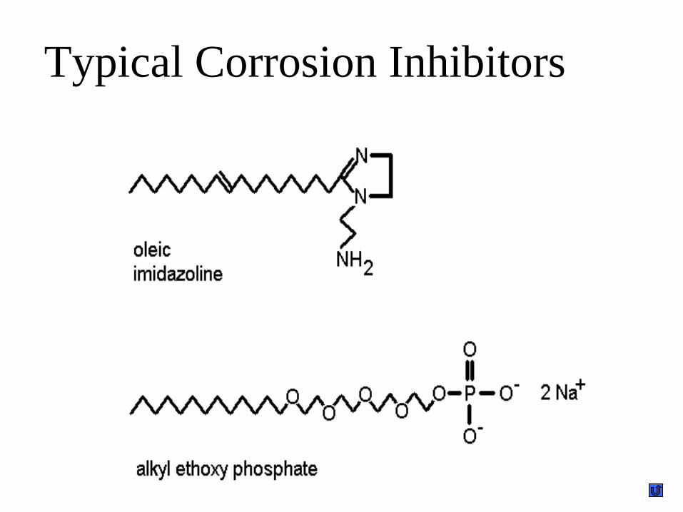
Typical Corrosion Inhibitors
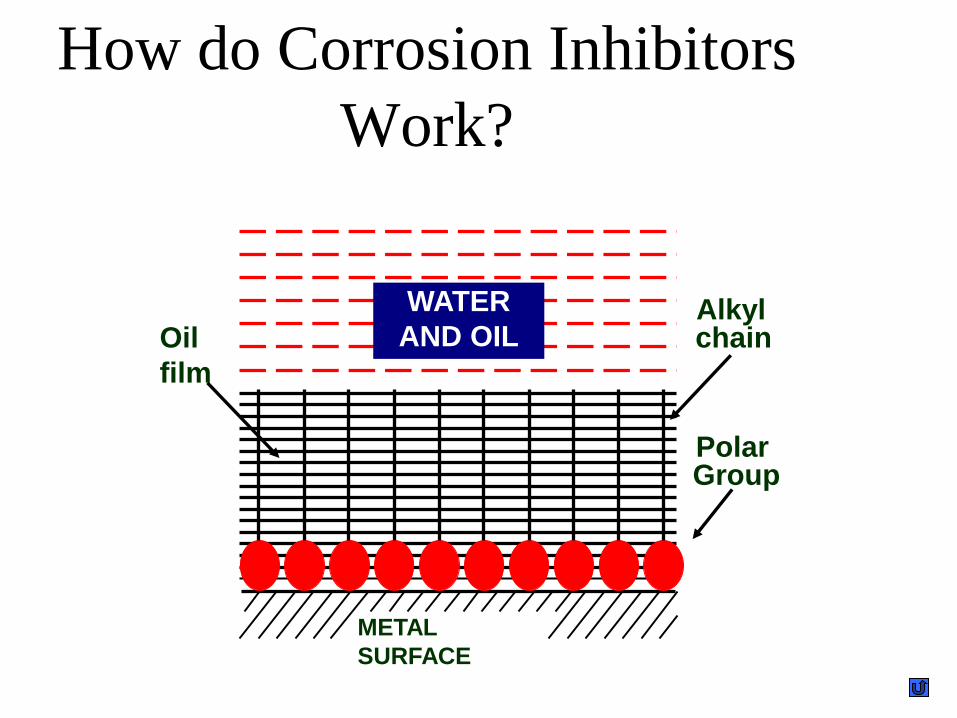
How do Corrosion Inhibitors
Work?
METAL
SURFACE
WATER
AND OIL
Polar Group
Alkyl chain Oil
film
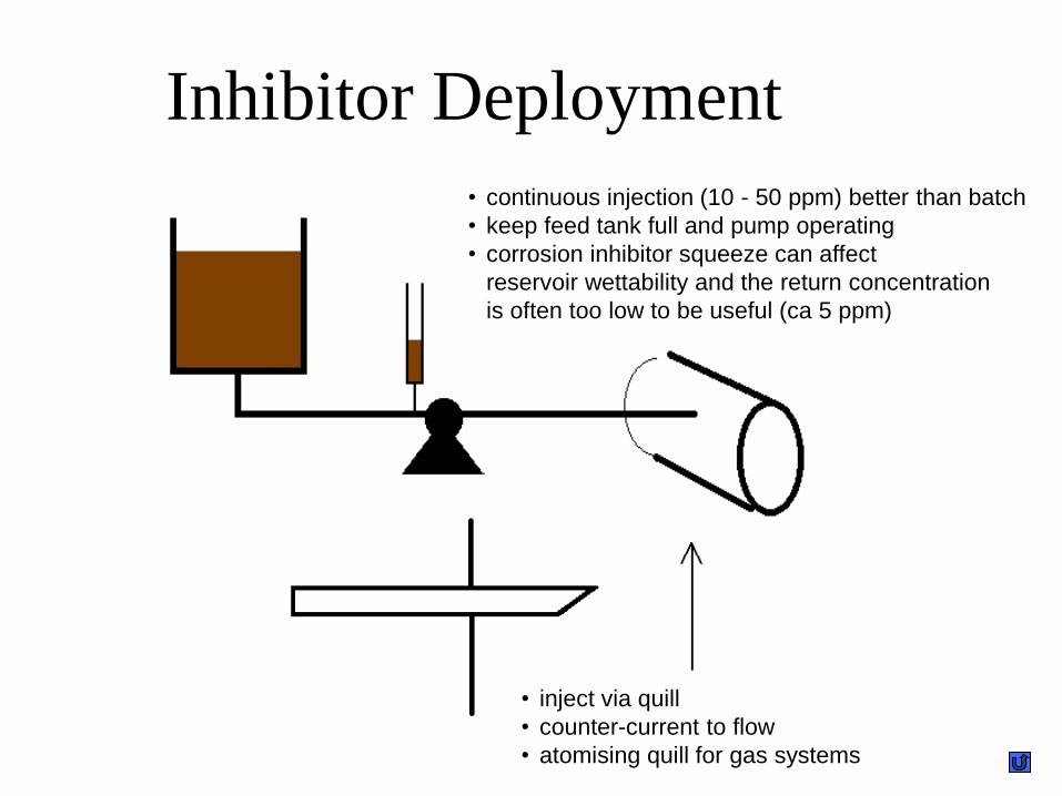
Inhibitor Deployment
• inject via quill
• counter-current to flow
• atomising quill for gas systems
• continuous injection (10 - 50 ppm) better than batch
• keep feed tank full and pump operating
• corrosion inhibitor squeeze can affect
reservoir wettability and the return concentration
is often too low to be useful (ca 5 ppm)