corrige ndun no.3 date :14.12 - … description: supply, supervision of erection & commissioning...
TRANSCRIPT

CORRIGE NDUN NO.3 DATE :14.12.2012
TENDER NO:1000175068
TENDER DESCRIPTION: SUPPLY, SUPERVISION OF ERECTION & COMMISSIONING OF DIESEL ENGINE
DRIVEN FIRE WATER PUMPS CONFORMING TO TAC (TARIFF ADVISORY
COMMITTEE)/NFPA(NATIONAL FIRE PROTECTION ASSOCIATION)
Please be informed that Document No. T-S-201( i.e. Specification for Pump ), Document No. T-S-203( i.e.
specification for Engine And Accessories) & Annexure IX (i.e. Life Cycle Cost loading) in respect of above
mentioned tender no. appeared in press on 23.11.2012 has been changed as per attached amendment
sheet enclosed i.e. Document No. T-S-201 (Rev) ,Document No. T-S-203 (Rev) and Annexure IX (Rev)
Further please refer to DATA sheet for Fire Pump (Doc.no. M-Dss-101) published in corrigendum no.2
dtd 04.12.2012, where Point 4 -h should be read as “Engine Control Panel along with Battery Charging
System” and vendor has to provide NPSH required under point no.2.
Average temperature to be considered for each location is 50⁰C (+/-5).
Due date has been extended upto 31.12.2012 time 3pm.
Kindly submit the signed copy of Corrigendum no.2 & no.3 as a token of your acceptance.

ANNEXURE IX (Rev)
LIFE CYCLE COST
TOTAL COST = U + WORKING COST + U * 0.06903 + U * 0.0999
U = CAPITAL COST (LANDED COST)
TOTAL WORKING COST = S.F.C * BKW *22560
S.F.C = SPECIFIC FUEL CONSUMPTION IN GM/kw-hr
BKW = BRAKE Kilo Watt of Deisel Engine
ASSUMPTIONS :- DENSITY OF HSD: 0.83 GMS /CC
C= Rs. 47 / ltr OF HSD
Z = 0.5 HRS RUNNING TWICE A WEEK AS PER OISD NORMS
Y = 8 * 12 (8 DAYS IN A MONTH FOR 12 MONTHS)
N = 10 YRS. OF WORKING
C * Z * Y * N = 22560
cost of HSD will be considered as per the rate prevalling on the date of price bid opening
TOTAL WORKING COST = SFC * BKW* 22560
DEPRICIATION :- 0.06903 * U
INTEREST :- 0.0999 * U

DOCUMENT PUMPS DOC. NO. T-S-201 (Rev) Sheet No. TITLE 1 of 8
SPECIFICATION FOR
PUMPS Document No.T-S-201(Rev)

DOCUMENT PUMPS DOC. NO. T-S-201 (Rev) Sheet No. TITLE 2 of 8
1.00.00 INTENT OF SPECIFICATION 1.01.00 The specification covers the design, construction features, manufacturing, performance testing and
deliver of horizontal centrifugal pumps to site in good condition, supervision during erection, pre-commissioning check up and commissioning.
1.02.00 In case of any contradiction between the specification clause and the standards specified. Bidder
shall follow the specification. In case of contradiction between this specification and data specification sheets, stipulation of the latter shall prevail.
2.00.00 CODES AND STANDARDS 2.01.00 The design, manufacturing and performance of the horizontal centrifugal pumps as specified
hereinafter shall comply with the requirements of the latest editions of the applicable codes and standards, in particular the following:
2.01.01 IS-1520 Horizontal Centrifugal pumps for clear, cold and fresh water. 2.01.02 IS-5120 Technical requirement for rotodynamic special purpose pumps. 2.01.03 IS-5659 Pumps for process water 2.01.04 IS-12469 Pumps for fire fighting system 2.01.05 IS-9137 Code for Acceptance Test for Centrifugal mixed flow and axial flow pumps – Class ‘C’. 2.01.06 ISO 3555/BS- Acceptance Test for Centrifugal mixed flow and axial Pumps. '5316, Part-2 Class ‘B’ tests. 2.01.07 ISO 2548/BS- -do- Class ‘C’ test. 5316, Part-1 2.01.08 PTC 8.2 Power Test Codes - Centrifugal pumps. 2.01.09 ASTM-E-165-65 Standard Method for liquid Penetrant Inspection
DOCUMENT PUMPS DOC. NO. T-S-201 (Rev) Sheet No. TITLE 3 of 8
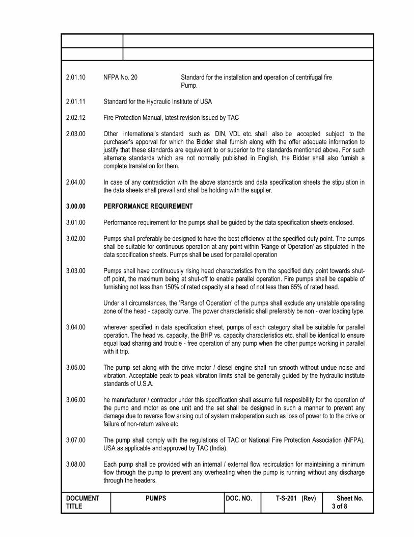
2.01.10 NFPA No. 20 Standard for the installation and operation of centrifugal fire Pump. 2.01.11 Standard for the Hydraulic Institute of USA 2.02.12 Fire Protection Manual, latest revision issued by TAC 2.03.00 Other international's standard such as DIN, VDL etc. shall also be accepted subject to the
purchaser's apporval for which the Bidder shall furnish along with the offer adequate information to justify that these standards are equivalent to or superior to the standards mentioned above. For such alternate standards which are not normally published in English, the Bidder shall also furnish a complete translation for them.
2.04.00 In case of any contradiction with the above standards and data specification sheets the stipulation in
the data sheets shall prevail and shall be holding with the supplier. 3.00.00 PERFORMANCE REQUIREMENT 3.01.00 Performance requirement for the pumps shall be guided by the data specification sheets enclosed. 3.02.00 Pumps shall preferably be designed to have the best efficiency at the specified duty point. The pumps
shall be suitable for continuous operation at any point within 'Range of Operation' as stipulated in the data specification sheets. Pumps shall be used for parallel operation
3.03.00 Pumps shall have continuously rising head characteristics from the specified duty point towards shut-
off point, the maximum being at shut-off to enable parallel operation. Fire pumps shall be capable of furnishing not less than 150% of rated capacity at a head of not less than 65% of rated head.
Under all circumstances, the 'Range of Operation' of the pumps shall exclude any unstable operating
zone of the head - capacity curve. The power characteristic shall preferably be non - over loading type. 3.04.00 wherever specified in data specification sheet, pumps of each category shall be suitable for parallel
operation. The head vs. capacity, the BHP vs. capacity characteristics etc. shall be identical to ensure equal load sharing and trouble - free operation of any pump when the other pumps working in parallel with it trip.
3.05.00 The pump set along with the drive motor / diesel engine shall run smooth without undue noise and
vibration. Acceptable peak to peak vibration limits shall be generally guided by the hydraulic institute standards of U.S.A.
3.06.00 he manufacturer / contractor under this specification shall assume full resposibility for the operation of
the pump and motor as one unit and the set shall be designed in such a manner to prevent any damage due to reverse flow arising out of system maloperation such as loss of power to to the drive or failure of non-return valve etc.
3.07.00 The pump shall comply with the regulations of TAC or National Fire Protection Association (NFPA),
USA as applicable and approved by TAC (India). 3.08.00 Each pump shall be provided with an internal / external flow recirculation for maintaining a minimum
flow through the pump to prevent any overheating when the pump is running without any discharge through the headers.

DOCUMENT PUMPS DOC. NO. T-S-201 (Rev) Sheet No. TITLE 4 of 8
4.00.00 DESIGN AND STANDARDS
4.01.00 Pump casing 4.01.01 Pump casing shall be provided with adequate number of vents and priming connections with valves
unless the pump is made self - venting and priming. Casing drain, as required, will be provided complete with drain valve.
4.01.02 Pump design must ensure that the nozzles are capable of withstanding external reactions not less
than those specified in relevant standards /codes.
4.01.03 In case where an expansion joint is located at pump suction, the pump assembly will be subject to an additional thrust which will be transmitted to the foundation. This additional thrust shall be taken into consideration while designing the pump.
4.02.00 Impeller 4.02.01 The rotor assembly shall be dynamically balance and design with critical speed substantially above the
operating speed. Impeller shall be of closed type. 4.03.00 Wearing Rings 4.03.01 Replaceable type wearing rings shall be furnished to prevent damage to impeller and casing. The rings
shall be so fitted as to prevent turning while the pump is in operation. 4.04.00 Shaft 4.04.01 Shaft size shall be selected considering that the critical speed shall be away from the operating speed
as recommended in applicable Code/Standard. The critical speed shall also be at least 10% away from runway speed.
4.05.00 Shaft Sleeves 4.05.01 Renewable type fine finished shaft sleeves shall be provided at the stuffing boxes / mechanical seats.
Length of the shaft sleeves must extend beyond the other faces of gland packing or seal end plate so as to distinguish between the leakage past shall be shaft sleeve and that past the seals/glands.
4.05.02 Shaft sleeves shall be properly fastened to the shaft to prevent any leakage or loosening. Shaft and
shall sleeve assembly should ensure concentric rotation. 4.06.00 Bearing 4.06.01 Bearing shall be easily accessible without disturbing the pump assembly. A drain plug shall be provided
at the bottom of each bearing housing. 4.06.02 Heavy duty sleeve/ball/roller type bearings, shall be provided to take care of the radial loads. 4.06.03 In case of sleeve type radial bearings, axial thrust shall be absorbed in suitable hydraulic devices and
/ or thrust bearings.

DOCUMENT PUMPS DOC. NO. T-S-201 (Rev) Sheet No. TITLE 5 of 8
4.06.04 Bearings and hydraulic devices (if provided for balancing axial thrust) shall be of adequate design for
taking the entire pump load arising from all probable conditions of continuous operation. Life of the bearings shall be highest possible. Thrust bearing shall be capable of running continuously at maximum load.
4.06.05 The bearing shall be oil/greases lubricated. Suitable lubricating arrangement for the bearing shall be
furnished completely with all accessories like pump, filters, piping, fittings, valves, interlocking and supervising instruments etc. as necessary and specified in the data sheets. The design shall be such that the bearing lubricant does not contaminate the liquid being pumped.
4.07.06 Stuffing Boxes Stuffing box design shall permit replacement of packing without removing any part other than the
gland. 4.07.07 Stuffing boxes shall be sealed/cooled by the fluid being pumped/external clear water, as indicated in
the Data Sheets, all necessary pumps, piping, fittings, valves, instruments etc. as required for safe and trouble free operation of the pumps and as specified in the Data sheet shall be included in the pump supplier’s scope of supply.
4.08.00 Drive Data The pump shall be driven by electrical motor directly coupled as specified in the data sheets. A heavy
duty coupling along with coupling guard shall be provided between the pump and drive unit. 5.00.00 INSPECTION AND TESTING The manufacturer shall conduct all tests and inspections (including stage inspections, as necessary)
required to ensure that the equipment offered by him conforms to the requirement of this specification, in particular, the data specification sheets. The particulars of the proposed tests incorporated in QAP and the procedures for the tests shall be submitted to the consultant / TPIA for approval before conducting the tests.
5.01.00 Material Test All materials used for pump construction shall be tested as per approved QAP. Physical and chemical
tests on materials shall be done to ensure the quality of the material offered. Test procedure and sampling shall be guided by the applicable test codes and standards. Components for which material test has been done and approved shall be stamped for identification. Pumps shall be offered for visual inspection and shall not be painted before inspection.
5.01.01 Pump components shall be subjected to non-destructive test (NDT), if asked for in data sheets.
Requirements of NDT and acceptable limits shall be guided by relevant standard(s). Components or batch subjected to successful NDT shall be stamped for identification.
5.02.00 Hydraulic Test 5.02.01 All pressure parts shall be subjected to hydrostatic pressure test at a pressure of 150% of shut off
head + 1.5 Kg/cm2. Or at 200% of the rated head + 1.5 Kg/cm2 whichever is higher for a period specified in testing standard or a maximum period of two(2) hours, whichever is more.

DOCUMENT PUMPS DOC. NO. T-S-201 (Rev) Sheet No. TITLE 6 of 8
5.03.00 Dynamic Balancing All rotating components of the pumps shall be static and dynamically balanced Dynamically balancing
tests shall be carried out at a speed not less than the rated RPM of the pump. Test procedure and acceptance limits shall be guided by the testing codes and standards.
5.04.00 Performance tests 5.04.01 Each pump shall be tested at manufacturer’s work in presence of purchaser’s representative with the
prime mover specified in Data Specification Sheets to determine pump performance. Prior to performance tests, the pump supplier shall furnish the procedure and methods of testing to the purchaser for approval.
5.04.02 Performance tests are to be conducted over the entire ‘Range of Operation’ of the pump including the shut off condition for minimum one hour. A minimum five sets of reading shall be taken covering the shut off point, rated point and the two extremeties of Range of Operation, to establish the performance curves.
5.04.03 Tests shall be conducted with actual drive motors being furnished and at the rated speed. Noise and vibration test shall be repeated at site after installation apart from shop testing.
5.04.04 NPSH ( R) test for the pump at rated discharge and 150% of rated discharge shall be conducted and
witnessed by TPIA 5.04.05 After installation and commissioning pumps shall be offered for performance guarantee test as per
agreed procedure. The supplier shall furnish all necessary instruments, accessories and personnel for site testing. The calibration curves of all instruments, permissible tolerance limit of instruments and test procedure shall be mutually agreed between the Purchaser and Supplier/Contractor. If the site performance test and results are unsatisfactory, the manufacturer/contractor shall rectify the pump at his own cost.
Couple Run test for 4 hours.( At both vendor’s premises and at Site) Mechanical Strip Test for pumps at vendor premises. Review of all Test Certificates by TPIA 6.00.00 DRAWINGS, DATA, CURVES AND MANUALS The bidder shall submit the following documents in eight sets to purchaser/consultant for approval
after award and manufacturing process shall be initiated only after obtaining approval. 6.01.01 Drawings i) Outline drawings showing the principal dimensions, weight and location of the suction and
discharge connections of the pumps offered.
ii) Typical cross-section drawing showing various components of the pumps with materials of construction etc.
iii) Pump foundation details along with all design loads, direction and points of application.

DOCUMENT PUMPS DOC. NO. T-S-201 (Rev) Sheet No. TITLE 7 of 8
iv) Drawing showing the lubrication system and sealing arrangement. 6.01.02 Data & Curves i) Anticipated performance curves showing the following characteristics:
a) Capacity Vs. head b) Capacity Vs. Power c) Capacity Vs. Efficiency d) Capacity Vs. NPSH required
ii) Completely filled in Technical particulars enclosed with this specification for final approval.
iii) A comprehensive write-up or brochure on the details of manufacturing and testing facilities in
the shop of the manufacturer.
iv) Complete descriptive and illustrated literature on the pump and accessories offered.
v) Any other data / information related to the erection and operation of the pump vi) Quality Assurance Plan.
vii) Shop / Site test procedure.
6.02.00 Instruction Manuals
a) The Instruction Manuals shall present the following basic categories of information in a comprehensive manner prepared for use by operating and/or maintenance personnel.
i) Instruction for erection.
ii) Instruction for pre-commissioning checkup, operation, abnormal conditions, maintenance and repair.
iii) Write-up on controls and interlocks provided. iv) Recommended inspection points and period of inspection v) Schedule of preventive and shut down maintenance indicating activity details, frequency,
duration, consumables/spares required, manpower/tools & tackles necessary etc.
vi) Ordering information for all replaceable spare parts with code number of parts etc. vii) Recommendation for type of lubricating points, frequency of lubricant changing schedule. viii) Assembly / disassembly sequency for capital maintenance of each component / sub – assembly. b) The information shall be organised in a logical and orderly sequence. A general description of
the equipment including significant technical characteristics shall be included to familiarise operating and maintenance personnel with the equipment.

DOCUMENT PUMPS DOC. NO. T-S-201 (Rev) Sheet No. TITLE 8 of 8
c) Necessary drawings and/or other illustrations shall be included and copies of appropriate final
drawings for the overall assembly as well as all sub-assembly component shall be bound in the manual. Test, adjustment and calibration information as appropriate shall be included and shall be identified to the specific equipment. Safety and other warning notice and installation, maintenance and operating cautions shall be emphasized.
d) A parts list shall be included showing part nomenclature, manufacturer’s part number and/or
other information necessary for accurate identification and ordering of replacement parts.
e) Instruction manuals shall be securely bound in durable folder.
f) The instruction Manual shall include the list of spare parts that have to be procured along with the equipments. It shall also include list of all special tools and tackle furnished with complete drawings and instruction for use of such tools tackles.
g) THREE sets of Instruction Manual, Approved QAP, As built Drawings, Inspection Release Note
by TPIA shall be submitted to owner at the time of supplies.

DOCUMENT ENGINE AND ACCESSORIES DOC. NO. T-S-203(Rev) Sheet No.
TITLE 1 of 13
SPECIFICATION FOR
ENGINE AND ACCESSORIES
Document No. T-S-203(Rev)

DOCUMENT ENGINE AND ACCESSORIES DOC. NO. T-S-203(Rev) Sheet No.
TITLE 2 of 13
1.00.00 INTENT OF SPECIFICATION This specification covers the design, performance, manufacturing, construction features and testing
and commissioning of compression ignition diesel engines, used primarily for driving centrifugal pumps, used for the purpose of fire fighting.
2.00.00 CODES AND STANDARDS The design, manufacturing, shop testing, erection, testing and commissioning of compression
ignition diesel engines shall conform to the latest revision of following standards and codes, in addition to other relevant standards and manufacturer's own standard :
2.01.00 IS-10000 : Methods of test for internal combustion Pt. I to XII engines
2.02.00 BS-5514 : Specification for reciprocating Internal Pt. I to VI Combustion
engines: Performance
2.03.00 ASME Power test : Internal Combustion Engine Code PTC - 17
2.04.00 Codes of Diesel Engine Manufacturer's Association, USA. 3.00.00 DESIGN AND CONSTRUCTION 3.01.01 General
The diesel engine shall be of multi-cylinder type multi stroke cycle with mechanical (airless) injection, cold starting type.
3.01.02 The continuous engine brake horse power rating (after accounting for all auxilary power consumption) at the site conditions shall be at least 20% greater than the requirement at the duty point of pump at rated RPM and in no case, less than the maximum power requirement at any range of operation of pump and also not less than the brake horse power required to drive the pump at 150 % of rated discharge , Derating factors, considered by the manufacturer to arrive at the shaft power of the diesel engine at site, shall not be less than the following for naturally aspirated engine only :
i) 3% for each 305 meter elevation above MSL. ii) 1% for each 5.6 C rise in air temperature above15.6 C.

DOCUMENT ENGINE AND ACCESSORIES DOC. NO. T-S-203(Rev) Sheet No.
TITLE 3 of 13
iii) For turbo-charged and after cooled engines, manufacturer shall furnish these derating factors and guarantee them.
3.01.03 The engine shall be designed with regard to ease of maintenance, repair, cleaning and inspection. This will also provide interchangeability of parts.
3.01.04 All parts subjected to substantial temperature changes shall be designed and supported to permit free expansion and contraction or without resulting in leakage, harmful distortion or mis-alignment.
3.01.05 The engine shall be designed for continuous operation at full load for a period of at least six (6)
hours. 3.01.06 Requirements of TAC Fire Protection Manual shall be complied with and Diesel engine
shall be approved by TAC.
Power requirement for engine shall be at 150% discharge without any allowances
3.02.00 Starting 3.02.01 The engine shall be capable of both automatic and manual start. The normal mode of starting is
automatic but in the failure of automatic start or at the discretion of the operator, the engine can be started remote-manually from the Diesel Engine Control panel.
Since the fire pumping unit driven by the diesel engine is not required to run continuously for long
period during routine testing and the operation will not be frequent, special feature shall be built into the engine to allow it to start within a very short period against full load even if it has remained idle for a considerable period.
3.02.02 The engine should be designed in such a way that it may be started by one operator, without any preliminary heating of the combustion chamber at the minimum ambient temperature specified and shall accept full load within 15 seconds from the receipt of signal to start. The engine should have provision for manual cranking facility.
3.02.03 Automatic cranking shall be effected by a D.C. motor having high starting torqueto overcome full
engine compressor. Starting power will be supplied from two sets of storage batteries. One set of battery is for automatic starting of the engine and the other provided as standby. A selector switch will be provided at the automatic starting control panel to select any of the two sets of battery for manual/auto starting of the engine. The automatic starting arrangement shall include, as a safe guard, a 'Repeat Start' feature, so that if the pinion of the starting motor does not engage the fly wheel at the first attempt, it is automatically retracted and after a short pause again will advance towards the fly wheel. This repeat start cycle will continue until the starter motor pinion engages with the starting ring on the fly wheel and cranks the engine. The battery capacity shall be adequate for ten (10) consecutive starts without recharging with a cold engine under full compression. The control panel to be supplied by the bidder to have dual battery charger and battery selection switch so that any set of battery can be selected for automatic operation.
The engine shall be provided with 2 sets of 24 volts heavy duty, traction type lead acid batteries encased in a hard rubber container. The battery shall have ample capacity to start the engine several times in succession. The battery sets shall be provided with automatic battery charging panel for each set.

DOCUMENT ENGINE AND ACCESSORIES DOC. NO. T-S-203(Rev) Sheet No.
TITLE 4 of 13
Engine shall be designed to start instantaneously against full load even if it has remained idle for long period.
3.02.04 The batteries shall be used exclusively for starting the diesel engine and kept fully charged all the
time in position. Arrangement for both trickle and booster charger shall be provided. At no time should battery be disconnected, so that it is not available to start-up the engine. The battery charger should comply with the requirements specified hereinafter.
3.03.00 Engine Shut Down Mechanism The engine shut-down mechanism shall be manually operated and return automatically to the
starting position after use. 3.04.00 Governing System 3.04.01 The engine shall be fitted with a speed control device which will control the speed under all
condition of load. 3.04.02 The governor shall offer the following featurers :
i) The engine shall be provided with an adjustable governor capable of controlling the
engine speed within 10% of its rated speed under any condition of load upto the full load rating. The governor shall be set to maintain rated pump speed at maximum pump load.
ii) Engine shall be provided with an over speed alarm device. It shall be arranged to give an
alarm at a speed approximately 20% above rated engine speed and for manual reset, such that the automatic engine controller will continue to show an over speed signal until the device is manually reset to normal operating position.
iii) The governor shall be suitable for operation without external power supply. iv) The engine shall be provided with an in-built tachometer to indicate RPM of the engine.
The engine is to be provided with a time totaliser (hour counter)
3.05.00 Fuel System 3.05.01 The diesel engine will run on high speed diesel oil.
3.05.02 The engine shall be provided with a fuel tank fitted with a level indicator and having adequate
capacity to hold sufficient fuel oil for minimum six (6) hours of full load run. The fuel oil tank shall be mounted adjacent to the engine. No fuel oil tank will be provided by the purchaser.
3.05.03 The fuel oil tank shall be constructed of welded steel (lead coated) as per relevant code. The outlet
of the tank shall be at a minimum height of 600 mm above the inlet and fuel injection pump of the diesel engine to ensure adequate pressure at suction of injection pump.
3.05.04 The fuel oil tank shall be provided with a sludge and sediment trap, so that the same is not carried to the injection pump. Adequate sized inspection and cleaning hole shall be provided to facilitate maintenance. The fuel shall be fed by gravity from adequately sized storage tanks for 6 hours duty. Tank shall be fitted with required accessories including magnetic level indicator, sludge sediment trap, etc.

DOCUMENT ENGINE AND ACCESSORIES DOC. NO. T-S-203(Rev) Sheet No.
TITLE 5 of 13
3.05.05 Pipe line carrying fuel oil shall be independent for each engine and gradually sloped from the tank to the injection pump. Any valve in this line shall be placed adjacent to the tank and kept locked in open position. A filter shall be incorporated in this fuel oil system and shall be mounted in an accessible position for cleaning.
3.05.06 Pipe joints shall not be soldered and plastic pipes shall not be used.
3.05.07 The complete fuel oil system shall be designed to avoid any air pocket in any partof the pipe work, fuel pump, sprayers/injectors, filter system, etc. No air relief cock is permitted. However, where air relief is essential, screwed plugs may be used.
3.06.00 Lubricating Oil System
Automatic pressure lubrication shall be provided by positive displacement pump driven by the crank shaft, taking suction from a pump and delivery through pressurised oil cooler and fine mesh filters to a main supply header fitted in the bed plate casing. High pressure oil shall be supplied to main and big end bearings, cam-shaft chain and gear drive, etc. Valve gear shall be lubricated at reduced pressure through a reducing valve and the came by an oil bath.
3.07.00 Cooling Water System
Cooling Water system with heat exchanger shall conform to the system specified in the fire protection manual of the Regional Committee of the Tariff Advisory Committee. Charge air cooling is not acceptable. The bidder shall clearly indicate in his offer the types of cooling system adopted.
3.08.00 Accessories 3.08.01 Metal guard shall be provided over couplings, fly wheel and other moving parts.
3.08.02 The engine shall be mounted on a base plate of fabricated steel construction. Adequate access
shall be provided to the big end and main bearings, cam shaft and governor drives, water jacket, etc.
3.08.03 Indicator cocks shall be mounted directly on the cylinder head and located in such a manner as to
permit operation of the indicator cocks without removing the valves operating gear covers.
3.08.04 The engine shall be provided with intake and discharge duct work, inlet filter and silencer, outlet
muffler, expansion joints, dampers, etc., as necessary for efficient operation. Intake air should be taken from inside the building in which the engine is located, but the exhaust should be discharged outside the building (a minimum of 15M route length envisaged) and the exhaust as per relevant code/standard, and shall be routed clearing man height. The exhaust system shall be suitably designed to prevent condensate flowing into the engine.
3.08.05 The fly wheel shall have graduated markings around the periphery to facilitatechecking of valve
and fuel pump timings. 3.08.06 The couplings between engine and pump shall allow each unit to be removed without disturbing
the other.

DOCUMENT ENGINE AND ACCESSORIES DOC. NO. T-S-203(Rev) Sheet No.
TITLE 6 of 13
3.09.00 Instrumentation The diesel engine shall be provided with adequate instrumentation. These shall include, but not
limited to the following :
a) Temperature indicator (contact type) in cooling water inlet and outlet. b) Temperature indicator in lubricating oil outlet from the oil cooler. c) Temperature indicator for each cylinder head. d) Pressure gauges (contact type) for lubricating oil systems. e) Differential pressure gauges (contact type) across strainers. f) Speed indicator g) Lubricating oil sump level indicator. h) Fuel oil tank level indicator i) Voltmeter and ammeter in battery charging circuit.
3.10.00 CONTROL PANEL WITH BATTERY CHARGER 3.10.01 This panel is meant for starting the engine manually from the panel itself or automatically whenever
there is a fall in pressure in the system. The panel circuitry shall be such that three starting commands of 5 Sec. duration each with interval of 15 Sec. shall be provided through timer circuit and the engine is expected to start within 3 Sec. When the engine starts, the oil pressure will develop and will give the 'Set Running' indication in the Control panel and further starting operation is automatically cut-off. In case the engine does not start within 3 Sec., the panel will give an audio/indication of "Start Failure".
3.10.02 The control panel shall have self diagnostic feature for monitoring the status of the engine and would provided the following indication, as a minimum:
i) Lubrication oil Pressure low ii) Lubrication oil Sump level low iii) Lubrication oil temperature high iv) Fuel oil level for tank low. v) Cooling water temperature high. vi) Set running vii) Engine fails to start viii) Over speed ix) Power on 3.10.03 The panel will also be provided with battery and battery charger. Each Diesel engine control panel
will have 2 Nos. of static battery charger units of air cooled design with each charger having capacity to recharge one set of battery at a timer with provision for selector switch to charge any of the battery sets. Battery charger shall be capable of meeting following requirements:
a) Float charging battery and supplying DC load. b) Boost charging drain battery in 8 hours time
Panel shall include battery charger that would keep batteries in fully charged condition .Also,
• Indication for pump
• Operating manual start
• Automatic system actuated by door switch located inside the panel

DOCUMENT ENGINE AND ACCESSORIES DOC. NO. T-S-203(Rev) Sheet No.
TITLE 7 of 13
The panel shall also have provision so that Fire pumps can be operated through logical startup automation.
Provisions in control panel i. Provisions for charging both sets of batteries simultaneously in trickle & boost mode.
ii. Automatic changeover from one set of batteries to another in case of failure of start after 3 cranks iii. Electrical relays & timers to be provided instead of thermal relays iv. Protection of batteries against Over charging
Indicators of health of battery, charging current & voltage. Electrical components used in control panel shall be SIEMENS / KAYEE / L&T 3.10.04 Details of the battery and battery charger is appended below : 3.10.04.01 INTENT OF SPECIFICATION The specification covers the design, performance, manufacturing, constructionfeatures and testing
of battery charger used primarily for starting the diesel engine driving the fire water pumps, booster pumps and giving control supply to various alarm/control panels.
3.10.04.02 GENERAL INFORMATION a) The equipment specified hereinafter are required for starting the diesel engines and other
supplies to various alarm/control panels. b) For each diesel engine there shall be two (2) sets of battery and (2) sets of battery charger.
One (1) set of battery is for automatic starting of the engine and other is provided as standby. A selector switch shall be provided at the control panel to select any one of the two (2) sets of battery for starting of the engine.
c) Separate battery backed DC system along with charger shall be provided for each panel of the fire protection system package.
d) The battery system for the alarm/control/annunciation panel shall have adequate capacity to
cater to all the momentary and short time loads within the panel in addition to supplying the continuously rated loads for a duration of 8 hours in the instant of A.C. supply failure.
e) Battery system for each diesel engine starting shall be large enough to crank the engine
twelve times successively, each for a duration of 10 secs., without any charging in between.
f) The bidder shall indicate the battery voltage and battery capacity in amperehour at ten (10)
hour discharge rate. The battery voltage at any time during operation shall not be less than the minimum voltage required for operation of the D.C loads.
4.10.04.03 CODES AND STANDARDS a) All equipments shall conform to the requirement of the latest revisions of the following codes
and standards. IS : 266 Sulfuric acid.

DOCUMENT ENGINE AND ACCESSORIES DOC. NO. T-S-203(Rev) Sheet No.
TITLE 8 of 13
IS : 1069 Marking and arrangement for switchgear busbars, main connections and
auxiliary wiring. IS : 1248 Water for storage battery. IS : 1146 Direct acting electrical indicating instruments.
IS : 1554 Hard rubber container for lead-acid storage battery.
IS : 1651 PVC insulated (heavy duty) electric cables.
IS : 1652 Stationary cells and batteries, lead-acid type with plante positive plates). IS : 2147 Degrees of protection provided by enclosures or low voltage switch-gear
and control gear. IS : 2208 HRC cartridge fuse-links upto 650 V.
IS : 3116 Sealing compound for lead acid batteries
IS : 3700 Essential ratings and characteristics of semi-conductor devices.
IS : 3895 Mono-crystalline semi-conductor rectified cells and stakes.
IS : 4047 Heavy duty air-break switches for voltage not exceeding 1000 V.
IS : 4064 Air break switches, air break disconnectors air break switch dis-connectors
and fuse combination units for voltage not exceeding 1000 V AC or 1200 DC.
IS : 4237 General requirements for switchgear and control gear for voltage not exceeding 1000 V.
IS : 4540 Mono-crystalline-semi-conductor rectifier assemblies and equipments. IS : 5154 Lead acid traction batteries. IS : 6071 Synthetic separator for lead acid batteries. b) Equipment equivalent to international specification shall conform to the requirements of the
latest revisions of the relevant Indian Standards or shall be superior. c) The equipment shall also conform to the latest Indian Electricity Act and Indian Electricity
Rules 4.10.04.04 GENERAL DESIGN a) The battery and battery charger shall be located indoor.
b) Battery

DOCUMENT ENGINE AND ACCESSORIES DOC. NO. T-S-203(Rev) Sheet No.
TITLE 9 of 13
i) The cells shall be lead acid type. ii) The plates shall be designed for maximum durability during all services conditions
including high rate of discharge and rapid fluctuation of load. iii) Each cell shall be assembled in heat resistant, shock absorbing container made of
suitable material with suitable provision of upper and lower electrolyte level indication. Sufficient sediment space shall be provided so that the cells will not have to be cleared out during normal life of the battery.
iv) The cells shall be sealed in type with anti-splash type vent plug.
v) Separator between plates shall permit free flow type of electrolyte. Separator shall
be made of acid resisting materials. Proper arrangement shall be adopted to keep end plated in position.
vi) The cell terminal posts shall be provided with connector bolts and nuts, effectively coated with lead to prevent corrosion. Lead or lead coated copper connectors shall be furnished to connect-up cells of battery set.
vii) Positive and negative terminal posts shall be clearly and indelibly marked for easy identification.
viii) The electrolyte shall be of battery grade sulfuric acid conforming to IS: 226-1961.
Water for storage batteries conforming to IS : 1069 shall be used in the preparation of the electrolyte.
ix) Suitable terminal board shall be provided with each battery bank to enable easy
terminal of Owner's cable instead of terminating it directly into the end cell.
x) The battery shall conform to IS : 1651 or 1652.
c) Battery Charger
i) The Bidder shall furnish the battery charging scheme complete all necessary accessories such as transformers, switches, fuses, starter, contractors, diodes, ammeters, voltmeters and other devices as required for trouble free operation. All devices and equipment shall conform to relevant Indian Standard or shall be technically superior to it.
ii) The battery charger shall be of static type preferably thyristor control. The
charges shall have selector switches for float and boost mode of operation. During float mode, the charger will operate in constant voltage mode with a voltage set potentiometer and trickle charge the associated battery as well as supply the continuous DC requirement. This means in normal operating conditions battery shall not be drained and kept ready for any contingency.
During boost selection, the charger will operate in constant current mode and
charge up the battery within eight hours. While boost charging the battery getting boost charge shall be isolated from the loads. Current and voltage range of the charger have to be adequate and approved by the Owner.
iii) All chargers shall be provided with facilities to select automatic and manual control of output voltage and current.

DOCUMENT ENGINE AND ACCESSORIES DOC. NO. T-S-203(Rev) Sheet No.
TITLE 10 of 13
iv) Charger shall have adjustable load limiter which shall not allow charger to exceed the set limit.
v) When on automate charge output voltage shall remain with + 1% of the set value
for an input voltage variation of + 10%.
vi) Voltage regulation of the charger with a loading from 0% to 100% shall not be more than 2%.
vii) Each charger shall be provided with AC input voltmeter with selector switch, DC
voltmeter and DC ammeter. All the instruments, switches and lamps shall be flush/semi-flush mounted on the panel.
viii) Charger panels shall have adequate number of annunciation windows and also facility for remote annunciations.
ix) Space heater of adequate capacity shall be provided to prevent moisture condensation in the panel.
x) The construction, fabrication and painting of the panel shall be as per Section
12 of The Technical Specification.
4.10.04.05 TESTING a) Following routine tests shall be carried out on all Battery chargers.
i) Compliance with approved dry, data sheet & specification. ii) Insulation resistance test. iii) H.V. (power frequency) test. iv) Temp rise test at full load. v) Voltage regulation test. vi) Performance test including load test. vii) Check for over voltage/under voltage protection & over current/short circuit
protection. viii) Check for degree of protection. ix) Burn in test on all Electronic modules/panels.
b) Batteries to be checked for make, type and rating.
3.10.05 The control panel will provide following indications also: a) Battery - A selected b) Battery - B selected c) Battery - A voltage low d) Battery - B voltage low e) Battery charger - I failure f) Battery charger - II failure g) Battery Voltage - Low 4.00.00 TESTING & INSPECTION

DOCUMENT ENGINE AND ACCESSORIES DOC. NO. T-S-203(Rev) Sheet No.
TITLE 11 of 13
4.01.00 The manufacturer shall conduct all tests required to ensure that the equipment furnished shall conform to the requirement of this specification and in compliance with requirements of applicable codes. The particulars of the proposed tests and procedure for the tests shall be submitted to the purchaser for approval before conducting the tests.
4.02.00 At manufacturer's works, tests shall be carried out during and after completion of manufacture of
different component parts and the assembly as applicable. Following tests shall be conducted :-
4.02.01 Material analysis and testing. 4.02.02 Hydrostatic pressure testing of all pressure parts. 4.02.03 Static and dynamic balance tests of rotating parts at applicable over speed and determination of
vibration level. DPT on machined parts of piston and cylinder. 4.02.04 Radiography and magna flux examination of materials and welds. 4.02.05 Ultrasonic testing of casting and forgings. Magnetic particale test on cam shafts. 4.02.06 Determination of capacity, efficiency and characteristic curves of all diesel driven pump.
4.02.07 Dimensional check on close tolerance items i.e. crank shaft, connecting rod, piston, cylinder bore,
piston liner etc. including roundness of piston. Calibration test of all fuel pumps, injectors, standard orifices, nozzles, instruments, etc.
4.02.08 Over speed test of the assembly at 120% of rated speed.
4.02.09 Power run test. 4.02.10 Performance test of the diesel engine to determine its torque, power and brake specific fuel
consumption at rated speed and other parameters as per quality plan to be approved by TPI/OWNER/CONSULTANT enclosed. Performance test of the engine shall carried out for one hour each at 1/4, 1/2, 3/4 load and for four hours at 110% full load as per IS : 1000/BS : 5514.
4.02.11 Function checks and adjustment of speed governor. 4.02.12 Overall mechanical and electrical inspection. 4.02.13 Check for vibration and noise level. 5.00.00 DRAWINGS, DATA, CURVES AND MANUALS
The bidder shall submit the following documents in eight sets to purchase/consultant for approved
after award and manufacturing process shall be initiated only after obtaining approved.
5.00.01 Drawings i) Outline drawing showing the principal dimensions weight and location of fly wheel.
ii) Typical cross-section drawing showing various components of the engine with material of
construction, etc.

DOCUMENT ENGINE AND ACCESSORIES DOC. NO. T-S-203(Rev) Sheet No.
TITLE 12 of 13
iii) Engine foundation details along with all design loads, directions and point of application.
iv) Drawing showing the lubrication arrangement.
5.00.02 Data & Curves i) Anticipated performance curves showing the following characteristics :
a) Engine speed vs. power output. b) Engine speed vs. Torque
ii) G.A. schematic drawings and terminal details of diesel engine control panel.
iii) Completely filled in particulars enclosed with the specification for final approval.
iv) A comprehensive write-up or brochure on the details of manufacturing and testing facilities
in the shop of the manufacturing.. v) Complete description and illustrated literature on the engine and accessories offered.
vi) Any other data/information related to the erection and operation of the engine. vii) Quality Assurance Plan. viii) Shop/Site test procedure. 7.02.00 Instruction Manuals:
a) The Instruction Manuals shall present the following basic categories of information in a comprehensive manner prepared for use by operating and / or maintenance personnel :
i) Instruction for erection ii) Instruction for pre-commissioning check-up, operation, abnormal conditions,
maintenance and repair. iii) Write-up on controls and interlocks provided. iv) Recommended inspection points and periods of inspection.
v) Schedule of preventive and shut down maintenance indicating activity details,
frequency, duration, consumable / spares required, manpower / tools & tackles necessary etc.
vi) Ordering information for all replaceable spare parts with code number of parts etc.
vii) Recommendation for type of lubricating points, frequency of lubricant changing
schedule.

DOCUMENT ENGINE AND ACCESSORIES DOC. NO. T-S-203(Rev) Sheet No.
TITLE 13 of 13
viii) Assembly / disassembly sequence for capital maintenance of each component / sub - assembly.
b) The information shall be organised in a logical and orderly sequence. A general description
of the equipment including significant technical characteristics shall be included to familiarise operating and maintenance personnel with the equipment.
c) Necessary drawings and / or other illustrations shall be included and copies of appropriate
final drawings for the overall assembly as well as all sub - assembly component shall be bound in the manual. Test, adjustment and calibration information, as appropriate, shall be included and shall be identified to the specific equipment. Safety and other warning notice and installation, maintenance and operating cautions shall be emphasized.
d) A parts list shall be included showing part nomenclature, manufacturer's part number and/or other information necessary for accurate identification and ordering of replacement parts.
e) Instruction Manuals shall be securely bound in durable folder. f) If a standard manual is furnished covering more than the specific equipment purchased, the
applicable model (or other identification) number, parts number and other information for the specific equipment purchased shall be clearly identified. Sectional drawings to suitable must be included in the instruction manual.
g) The instruction Manual shall include the list of spare parts that have to be procured along
with the equipments. It shall also include list of all special tools and tackle furnished with complete drawings and instruction for use of such tools tackles.
8.0 COMMISSIONING:
1. The supplier shall provide the services for commissioning of the pumps. However, the erection shall be
done by BPCL for which the layout drawings etc. for foundation details and other details shall be given by the vendor well in advance.
2. The vendor shall supply other accessories which are not specified above but are required for Successful
commissioning of the Fire Fighting pump assembly and its trouble free operation. 3. The equipment shall be under guarantee period of one year after the actual date of commissioning. Vendor
shall demonstrate actual performance test at site.