corp. 1241-l9 cbx25uh december 2012 service literature
TRANSCRIPT
Page 1
CBX25UHService Literature
Corp. 1241-L9December 2012
INSTALLATION AND SERVICE PROCEDURE
Revised August, 2018
CBX25UH Series
WARNINGImproper installation, adjustment, alteration, service ormaintenance can cause personal injury, loss of life, ordamage to property.
Installation and service must be performed by a licensedprofessional installer (or equivalent) or a service agency.
CAUTIONPhysical contact with metal edges and corners whileapplying excessive force or rapid motion can result inpersonal injury. Be aware of, and use caution whenworking near these areas during installation or whileservicing this equipment.
IMPORTANTThe Clean Air Act of 1990 bans the intentional venting ofrefrigerant (CFCs, HCFCs and HFCs) as of July 1, 1992.Approved methods of recovery, recycling or reclaimingmust be followed. Fines and/or incarceration may belevied for noncompliance.
Table of Contents
Unit Dimensions 2. . . . . . . . . . . . . . . . . . . . . . . . . . . .
Specifications / Electrical Data 3. . . . . . . . . . . . . . . .
Model Number Information 4. . . . . . . . . . . . . . . . . . .
Blower Data 4. . . . . . . . . . . . . . . . . . . . . . . . . . . . . . . .
Application 6. . . . . . . . . . . . . . . . . . . . . . . . . . . . . . . . .
Unit Components 6. . . . . . . . . . . . . . . . . . . . . . . . . . . .
Optional ECB25 Electric Heat 7. . . . . . . . . . . . . . . . .
Configuration Modification 10. . . . . . . . . . . . . . . . . . .
Electrical Connections 16. . . . . . . . . . . . . . . . . . . . . .
Wiring Diagrams 17. . . . . . . . . . . . . . . . . . . . . . . . . . .
Start-Up Operations 19. . . . . . . . . . . . . . . . . . . . . . . .
Sequence of Operations 20. . . . . . . . . . . . . . . . . . . .
Performance Checklists 21. . . . . . . . . . . . . . . . . . . . .
The CBX25UH are high-efficiency air handler. Several modelsare available in sizes ranging from 1‐1/2 through 5-tons. TheCBX25UH is designed for HFC-410A refrigerant.
CBX25UH series units are designed to be matched with eithera13 SEER air conditioner or heat pump, but can be matchedwith other air conditioners or heat pumps as noted in the ratinginformation. See Product Specification bulletin.
This air handler is designed for indoor installation only. Asshipped, the unit is ready for installation in either upflow orhorizontal left-hand. Field modifications are required forright-hand air discharge applications. Electric heat, downflow air discharge application kits, air filters and othervarious accessories are available and listed in theCBX25UH Product Specification bulletin for ordering.
All units come with a factory installed check/expansionvalve.
Information contained in this manual is intended for use byexperienced licensed HVAC service technicians only. Allspecifications are subject to change. Procedures outlined inthis manual are presented as a recommendation only and donot supersede or replace local or state codes.
Page 2
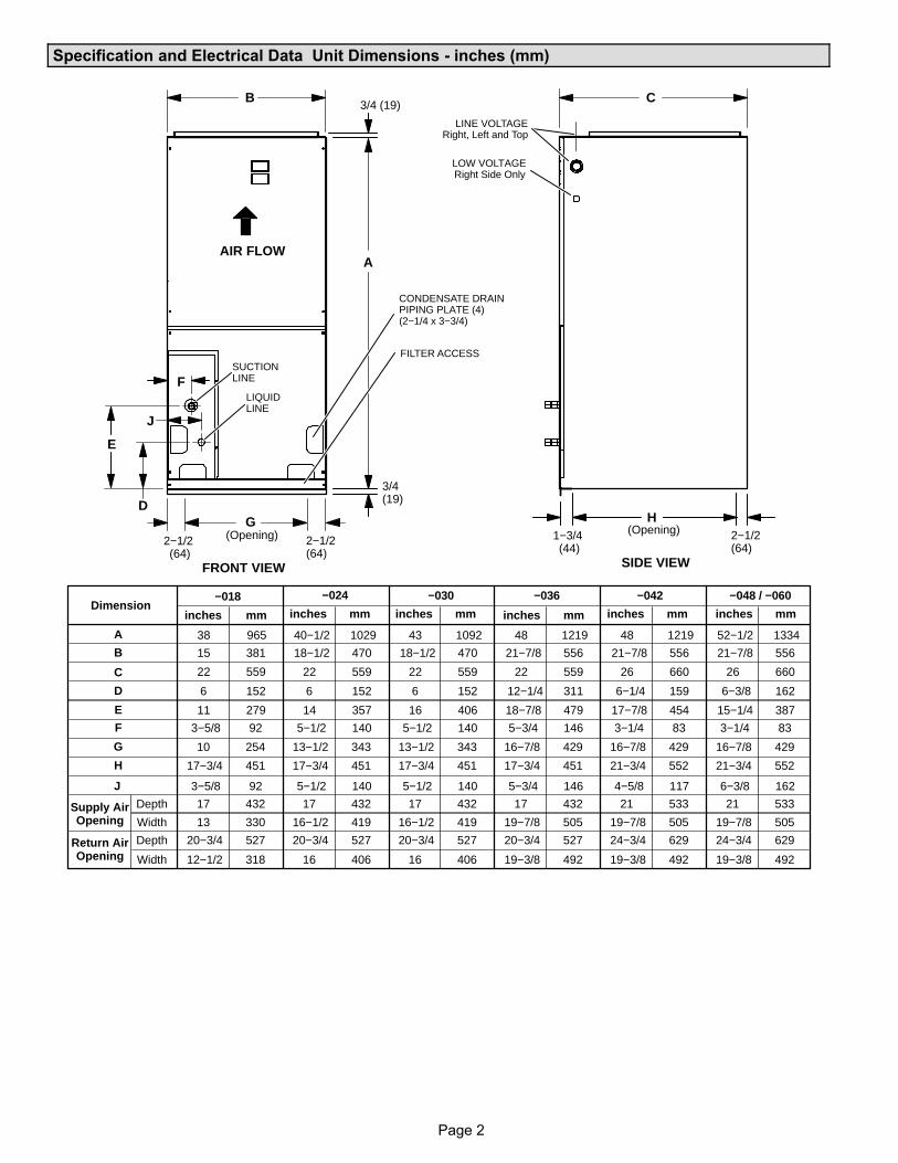
Specification and Electrical Data Unit Dimensions - inches (mm)
6−3/8 162
52−1/2 1334
21−7/8 556
26 660
6−3/8 162
15−1/4 387
3−1/4 83
16−7/8 429
21−3/4 552
21 533
19−7/8 505
24−3/4 629
19−3/8 492
4−5/8 117
48 1219
21−7/8 556
26 660
6−1/4 159
17−7/8 454
3−1/4 83
16−7/8 429
21−3/4 552
21 533
19−7/8 505
24−3/4 629
19−3/8 492
5−3/4 146
48 1219
21−7/8 556
22 559
12−1/4 311
18−7/8 479
5−3/4 146
16−7/8 429
17−3/4 451
17 432
19−7/8 505
20−3/4 527
19−3/8 492
5−1/2 140
43 1092
18−1/2 470
22 559
6 152
16 406
5−1/2 140
13−1/2 343
17−3/4 451
17 432
16−1/2 419
20−3/4 527
16 406
5−1/2 140
40−1/2 1029
18−1/2 470
22 559
6 152
14 357
5−1/2 140
13−1/2 343
17−3/4 451
17 432
16−1/2 419
20−3/4 527
16 406
3−5/8 92
inches mminches mm inches mminches mm
−048 / −060−042−036−030−018
A
CB
D
E
F
FRONT VIEW SIDE VIEW
LINE VOLTAGERight, Left and Top
LOW VOLTAGERight Side Only
SUCTIONLINE
LIQUIDLINE
FILTER ACCESS
CONDENSATE DRAINPIPING PLATE (4)(2−1/4 x 3−3/4)
3/4 (19)
AIR FLOW
H
2−1/2(64)
2−1/2(64)
2−1/2(64)
1−3/4(44)
(Opening) (Opening)G
3/4(19)
J
J
Dimension−024
inches mm inches mm
A 38 965
B 15 381
C 22 559
D 6 152
E 11 279
F 3−5/8 92
G 10 254
H 17−3/4 451
Supply AirOpening
Depth 17 432
Width 13 330
Return AirOpening
Depth 20−3/4 527
Width 12−1/2 318
Page 3
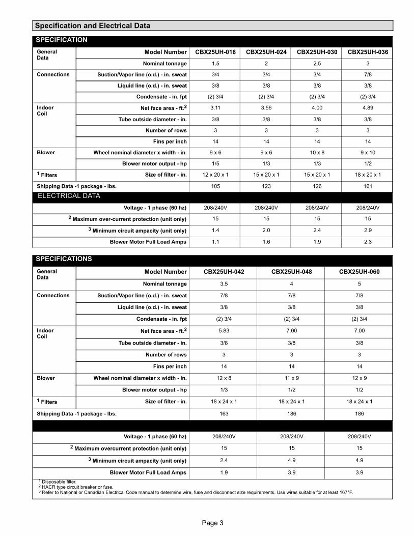
Specification and Electrical Data
SPECIFICATION
GeneralData
Model Number CBX25UH018 CBX25UH024 CBX25UH030 CBX25UH036
Nominal tonnage 1.5 2 2.5 3
Connections Suction/Vapor line (o.d.) in. sweat 3/4 3/4 3/4 7/8
Liquid line (o.d.) in. sweat 3/8 3/8 3/8 3/8
Condensate in. fpt (2) 3/4 (2) 3/4 (2) 3/4 (2) 3/4
IndoorCoil
Net face area ft.2 3.11 3.56 4.00 4.89
Tube outside diameter in. 3/8 3/8 3/8 3/8
Number of rows 3 3 3 3
Fins per inch 14 14 14 14
Blower Wheel nominal diameter x width in. 9 x 6 9 x 6 10 x 8 9 x 10
Blower motor output hp 1/5 1/3 1/3 1/2
1 Filters Size of filter in. 12 x 20 x 1 15 x 20 x 1 15 x 20 x 1 18 x 20 x 1
Shipping Data 1 package lbs. 105 123 126 161
ELECTRICAL DATA
Voltage 1 phase (60 hz) 208/240V 208/240V 208/240V 208/240V
2 Maximum over-current protection (unit only) 15 15 15 15
3 Minimum circuit ampacity (unit only) 1.4 2.0 2.4 2.9
Blower Motor Full Load Amps 1.1 1.6 1.9 2.3
SPECIFICATIONS
GeneralData
Model Number CBX25UH042 CBX25UH048 CBX25UH060
Nominal tonnage 3.5 4 5
Connections Suction/Vapor line (o.d.) in. sweat 7/8 7/8 7/8
Liquid line (o.d.) in. sweat 3/8 3/8 3/8
Condensate in. fpt (2) 3/4 (2) 3/4 (2) 3/4
IndoorCoil
Net face area ft.2 5.83 7.00 7.00
Tube outside diameter in. 3/8 3/8 3/8
Number of rows 3 3 3
Fins per inch 14 14 14
Blower Wheel nominal diameter x width in. 12 x 8 11 x 9 12 x 9
Blower motor output hp 1/3 1/2 1/2
1 Filters Size of filter in. 18 x 24 x 1 18 x 24 x 1 18 x 24 x 1
Shipping Data 1 package lbs. 163 186 186
ELECTRICAL DATA
Voltage 1 phase (60 hz) 208/240V 208/240V 208/240V
2 Maximum overcurrent protection (unit only) 15 15 15
3 Minimum circuit ampacity (unit only) 2.4 4.9 4.9
Blower Motor Full Load Amps 1.9 3.9 3.9
1 Disposable filter.2 HACR type circuit breaker or fuse.3 Refer to National or Canadian Electrical Code manual to determine wire, fuse and disconnect size requirements. Use wires suitable for at least 167°F.
Page 4
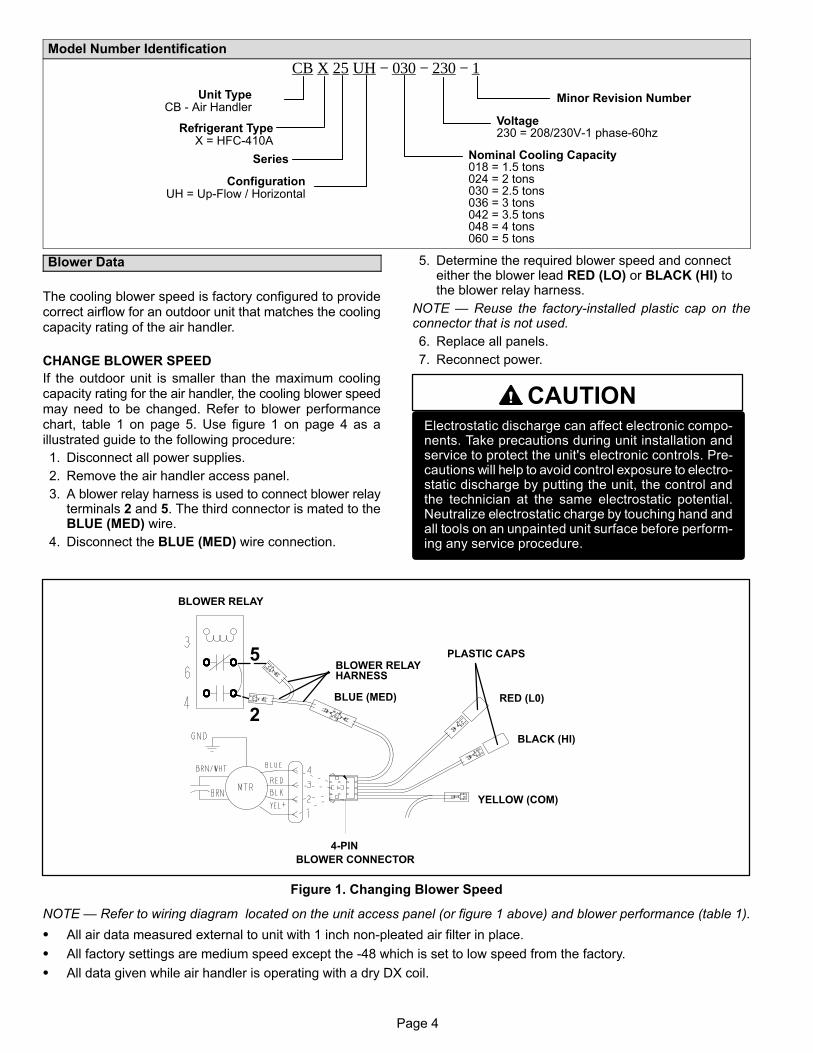
Model Number Identification
Unit TypeCB - Air Handler
Series Nominal Cooling Capacity018 = 1.5 tons024 = 2 tons030 = 2.5 tons036 = 3 tons042 = 3.5 tons048 = 4 tons060 = 5 tons
ConfigurationUH = Up-Flow / Horizontal
CB X 25 UH − 030 − 230 − 1
Refrigerant TypeX = HFC-410A
Minor Revision Number
Voltage230 = 208/230V-1 phase-60hz
Blower Data
The cooling blower speed is factory configured to providecorrect airflow for an outdoor unit that matches the coolingcapacity rating of the air handler.
CHANGE BLOWER SPEED
If the outdoor unit is smaller than the maximum coolingcapacity rating for the air handler, the cooling blower speedmay need to be changed. Refer to blower performancechart, table 1 on page 5. Use figure 1 on page 4 as aillustrated guide to the following procedure:
1. Disconnect all power supplies.
2. Remove the air handler access panel.
3. A blower relay harness is used to connect blower relayterminals 2 and 5. The third connector is mated to theBLUE (MED) wire.
4. Disconnect the BLUE (MED) wire connection.
5. Determine the required blower speed and connecteither the blower lead RED (LO) or BLACK (HI) tothe blower relay harness.
NOTE — Reuse the factory-installed plastic cap on theconnector that is not used.
6. Replace all panels.
7. Reconnect power.
CAUTIONElectrostatic discharge can affect electronic components. Take precautions during unit installation andservice to protect the unit's electronic controls. Precautions will help to avoid control exposure to electrostatic discharge by putting the unit, the control andthe technician at the same electrostatic potential.Neutralize electrostatic charge by touching hand andall tools on an unpainted unit surface before performing any service procedure.
2BLUE (MED) RED (L0)
BLACK (HI)
YELLOW (COM)
5BLOWER RELAY
BLOWER RELAY
PLASTIC CAPS
4-PIN
BLOWER CONNECTOR
HARNESS
Figure 1. Changing Blower Speed
NOTE — Refer to wiring diagram located on the unit access panel (or figure 1 above) and blower performance (table 1).
� All air data measured external to unit with 1 inch non-pleated air filter in place.
� All factory settings are medium speed except the -48 which is set to low speed from the factory.
� All data given while air handler is operating with a dry DX coil.
Page 5
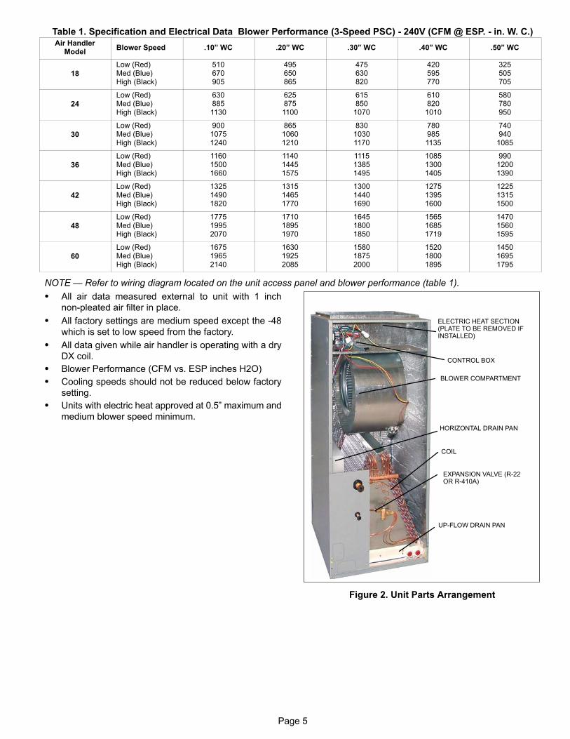
Table 1. Specification and Electrical Data Blower Performance (3-Speed PSC) - 240V (CFM @ ESP. - in. W. C.)Air Handler
ModelBlower Speed .10” WC .20” WC .30” WC .40” WC .50” WC
18
Low (Red)Med (Blue)High (Black)
510670905
495650865
475630820
420595770
325505705
24
Low (Red)Med (Blue)High (Black)
6308851130
6258751100
6158501070
6108201010
580780950
30
Low (Red)Med (Blue)High (Black)
90010751240
86510601210
83010301170
7809851135
7409401085
36
Low (Red)Med (Blue)High (Black)
116015001660
114014451575
111513851495
108513001405
99012001390
42
Low (Red)Med (Blue)High (Black)
132514901820
131514651770
130014401690
127513951600
122513151500
48
Low (Red)Med (Blue)High (Black)
177519952070
171018951970
164518001850
156516851719
147015601595
60
Low (Red)Med (Blue)High (Black)
167519652140
163019252085
158018752000
152018001895
145016951795
NOTE — Refer to wiring diagram located on the unit access panel and blower performance (table 1).
� All air data measured external to unit with 1 inch
non-pleated air filter in place.
� All factory settings are medium speed except the -48
which is set to low speed from the factory.
� All data given while air handler is operating with a dry
DX coil.
� Blower Performance (CFM vs. ESP inches H2O)
� Cooling speeds should not be reduced below factory
setting.
� Units with electric heat approved at 0.5” maximum and
medium blower speed minimum.
ELECTRIC HEAT SECTION(PLATE TO BE REMOVED IFINSTALLED)
CONTROL BOX
BLOWER COMPARTMENT
COIL
HORIZONTAL DRAIN PAN
EXPANSION VALVE (R-22OR R-410A)
UP-FLOW DRAIN PAN
Figure 2. Unit Parts Arrangement
Page 6
Application
All major blower coil components must be matchedaccording to Lennox recommendations for the unit to becovered under warranty. Refer to the Product Specificationbulletin for approved system matchups. A misapplied systemwill cause erratic operation and can result in early unit failure.The units come with factory installed check and expansionvalve for all applications. The TXV valve has been installedinternally for a cleaner installation and is accessible if required.
Unit Components
CONTROL BOX
The CBX25UH control box is located above the blowersection shown in figure 2. Line voltage and electric heatconnections are made in the control box. Optional electricheat fits through an opening located in the center of thecontrol box. When electric heat is not used, cover platescover the opening. The electric heat control arrangement isdetailed in the electric heat section of this manual.
TRANSFORMER
All CBX25UH series units use a single line voltage to24VAC transformer mounted in the control box. Thetransformer supplies power to the control circuits in theindoor and outdoor unit. Transformers are rated at 40VA.208/240VAC single phase transformers use two primaryvoltage taps as shown in figure 3.
BLUE
YELLOW
ORANGE
RED
BLACK
240 VOLTS
208 VOLTS
PRIMARY SECONDARY
Figure 3. 208/240 Volt Transformer
BLOWER RELAY
All CBX25UH units use a double-pole single-throw(DPST) switch relay to energize the blower motor. Therelay coil is energized by blower demand from indoorthermostat. When the coil is energized, a set of normallyopen (N.O.) contacts closes to energize the blower motor oncooling speed. When de-energized, a set of normally closed(N.C.) contacts allows the electric heat relay to energize theblower on heating speed (refer to unit wiring diagram).
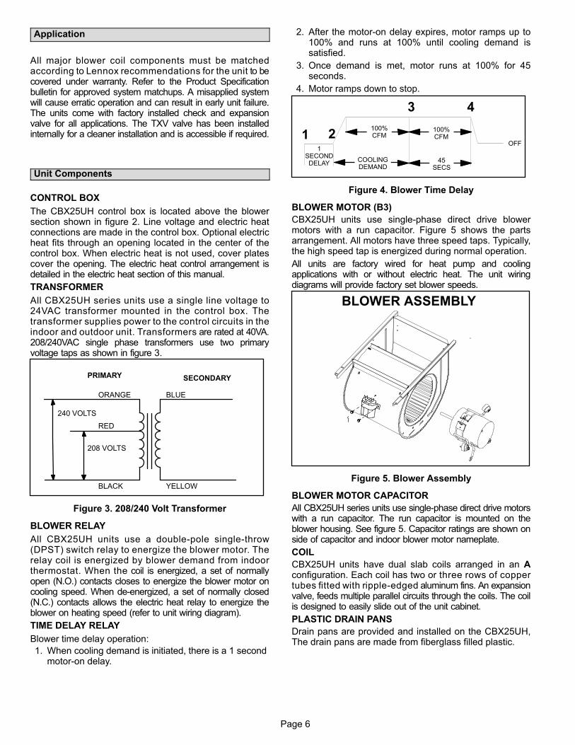
TIME DELAY RELAY
Blower time delay operation:
1. When cooling demand is initiated, there is a 1 second motor-on delay.
2. After the motor-on delay expires, motor ramps up to100% and runs at 100% until cooling demand issatisfied.
3. Once demand is met, motor runs at 100% for 45seconds.
4. Motor ramps down to stop.
1SECONDDELAY
OFF
100%CFM
100%CFM
45SECS
COOLINGDEMAND
1 2
3 4
Figure 4. Blower Time Delay
BLOWER MOTOR (B3)
CBX25UH units use single-phase direct drive blowermotors with a run capacitor. Figure 5 shows the partsarrangement. All motors have three speed taps. Typically,the high speed tap is energized during normal operation.
All units are factory wired for heat pump and coolingapplications with or without electric heat. The unit wiringdiagrams will provide factory set blower speeds.
BLOWER ASSEMBLY
Figure 5. Blower Assembly
BLOWER MOTOR CAPACITOR
All CBX25UH series units use single-phase direct drive motorswith a run capacitor. The run capacitor is mounted on theblower housing. See figure 5. Capacitor ratings are shown onside of capacitor and indoor blower motor nameplate.
COIL
CBX25UH units have dual slab coils arranged in an Aconfiguration. Each coil has two or three rows of coppertubes fitted with ripple-edged aluminum fins. An expansionvalve, feeds multiple parallel circuits through the coils. The coilis designed to easily slide out of the unit cabinet.
PLASTIC DRAIN PANS
Drain pans are provided and installed on the CBX25UH,The drain pans are made from fiberglass filled plastic.
Page 7
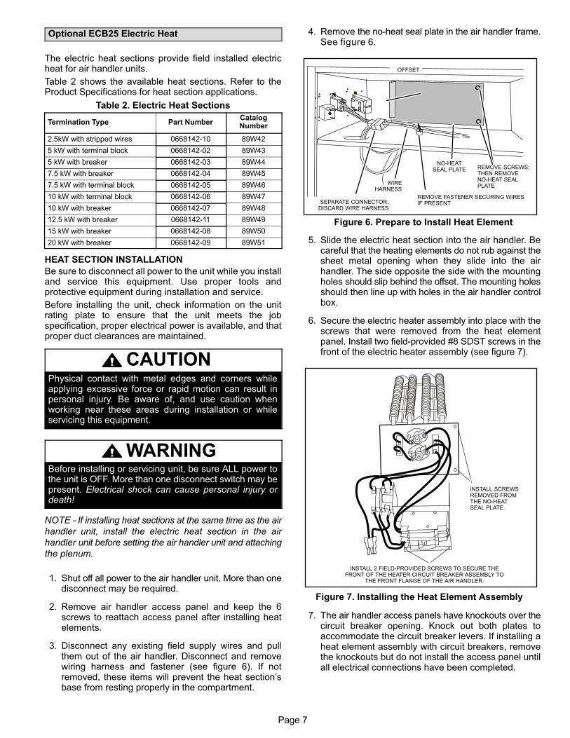
Optional ECB25 Electric Heat
The electric heat sections provide field installed electricheat for air handler units.
Table 2 shows the available heat sections. Refer to theProduct Specifications for heat section applications.
Table 2. Electric Heat Sections
Termination Type Part NumberCatalogNumber
2.5kW with stripped wires 0668142-10 89W42
5 kW with terminal block 0668142-02 89W43
5 kW with breaker 0668142-03 89W44
7.5 kW with breaker 0668142-04 89W45
7.5 kW with terminal block 0668142-05 89W46
10 kW with terminal block 0668142-06 89W47
10 kW with breaker 0668142-07 89W48
12.5 kW with breaker 0668142-11 89W49
15 kW with breaker 0668142-08 89W50
20 kW with breaker 0668142-09 89W51
HEAT SECTION INSTALLATION
Be sure to disconnect all power to the unit while you installand service this equipment. Use proper tools andprotective equipment during installation and service.
Before installing the unit, check information on the unitrating plate to ensure that the unit meets the jobspecification, proper electrical power is available, and thatproper duct clearances are maintained.
CAUTIONPhysical contact with metal edges and corners whileapplying excessive force or rapid motion can result inpersonal injury. Be aware of, and use caution whenworking near these areas during installation or whileservicing this equipment.
WARNINGBefore installing or servicing unit, be sure ALL power tothe unit is OFF. More than one disconnect switch may bepresent. Electrical shock can cause personal injury ordeath!
NOTE - If installing heat sections at the same time as the air
handler unit, install the electric heat section in the air
handler unit before setting the air handler unit and attaching
the plenum.
1. Shut off all power to the air handler unit. More than onedisconnect may be required.
2. Remove air handler access panel and keep the 6screws to reattach access panel after installing heatelements.
3. Disconnect any existing field supply wires and pullthem out of the air handler. Disconnect and removewiring harness and fastener (see figure 6). If notremoved, these items will prevent the heat section’sbase from resting properly in the compartment.
4. Remove the no-heat seal plate in the air handler frame.See figure 6.
Figure 6. Prepare to Install Heat Element
NO‐HEATSEAL PLATE REMOVE SCREWS;
THEN REMOVENO-HEAT SEALPLATE
SEPARATE CONNECTOR;DISCARD WIRE HARNESS
WIREHARNESS
OFFSET
REMOVE FASTENER SECURING WIRESIF PRESENT
5. Slide the electric heat section into the air handler. Becareful that the heating elements do not rub against thesheet metal opening when they slide into the airhandler. The side opposite the side with the mountingholes should slip behind the offset. The mounting holesshould then line up with holes in the air handler controlbox.
6. Secure the electric heater assembly into place with thescrews that were removed from the heat elementpanel. Install two field-provided #8 SDST screws in thefront of the electric heater assembly (see figure 7).
INSTALL SCREWSREMOVED FROMTHE NO-HEATSEAL PLATE.
INSTALL 2 FIELD-PROVIDED SCREWS TO SECURE THEFRONT OF THE HEATER CIRCUIT BREAKER ASSEMBLY TO
THE FRONT FLANGE OF THE AIR HANDLER.
Figure 7. Installing the Heat Element Assembly
7. The air handler access panels have knockouts over thecircuit breaker opening. Knock out both plates toaccommodate the circuit breaker levers. If installing aheat element assembly with circuit breakers, removethe knockouts but do not install the access panel untilall electrical connections have been completed.
Page 8
IMPORTANT - To remove knockouts, knock them out in the
same direction the punch did. Always start with the smallest
knockout and work outward to the knockout for the
appropriately-sized hole.
WARNINGFoil face insulation must be cut to eliminate the possibilityfor any frayed foil to coming in contact with any main orlow voltage connections. Insulation must be kept aminimum of 1/2” away from any electrical connection.
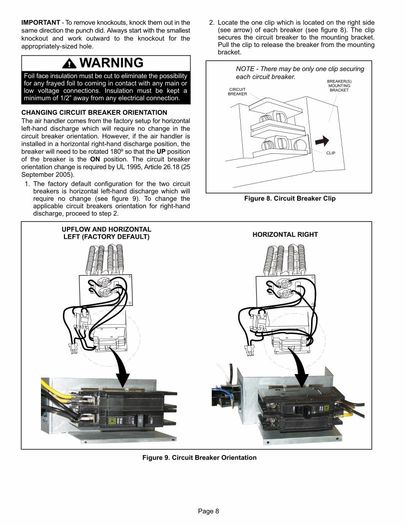
CHANGING CIRCUIT BREAKER ORIENTATION
The air handler comes from the factory setup for horizontalleft-hand discharge which will require no change in thecircuit breaker orientation. However, if the air handler isinstalled in a horizontal right-hand discharge position, thebreaker will need to be rotated 180º so that the UP positionof the breaker is the ON position. The circuit breakerorientation change is required by UL 1995, Article 26.18 (25September 2005).
1. The factory default configuration for the two circuitbreakers is horizontal left-hand discharge which willrequire no change (see figure 9). To change theapplicable circuit breakers orientation for right-handdischarge, proceed to step 2.
2. Locate the one clip which is located on the right side(see arrow) of each breaker (see figure 8). The clipsecures the circuit breaker to the mounting bracket.Pull the clip to release the breaker from the mountingbracket.
CLIP
BREAKER(S)MOUNTINGBRACKET
NOTE - There may be only one clip securing
each circuit breaker.
CIRCUITBREAKER
Figure 8. Circuit Breaker Clip
UPFLOW AND HORIZONTALLEFT (FACTORY DEFAULT) HORIZONTAL RIGHT
Figure 9. Circuit Breaker Orientation
Page 9
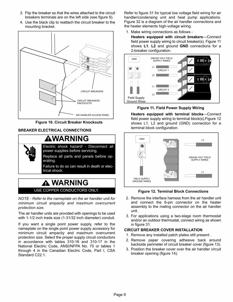
3. Flip the breaker so that the wires attached to the circuitbreakers terminals are on the left side (see figure 9).
4. Use the black clip to reattach the circuit breaker to themounting bracket.
CIRCUIT BREAKERS
AIR HANDLER ACCESS PANEL
CIRCUIT BREAKERSKNOCKOUTS
Figure 10. Circuit Breaker Knockouts
BREAKER ELECTRICAL CONNECTIONS
WARNINGElectric shock hazard! - Disconnect allpower supplies before servicing.
Replace all parts and panels before operating.
Failure to do so can result in death or electrical shock.
WARNINGUSE COPPER CONDUCTORS ONLY.
NOTE - Refer to the nameplate on the air handler unit for
minimum circuit ampacity and maximum overcurrent
protection size.
The air handler units are provided with openings to be usedwith 1-1/2 inch trade size (1-31/32 inch diameter) conduit.
If you want a single point power supply, refer to thenameplate on the single point power supply accessory forminimum circuit ampacity and maximum overcurrentprotection size. Select the proper supply circuit conductorsin accordance with tables 310-16 and 310-17 in theNational Electric Code, ANSI/NFPA No. 70 or tables 1through 4 in the Canadian Electric Code, Part I, CSAStandard C22.1.
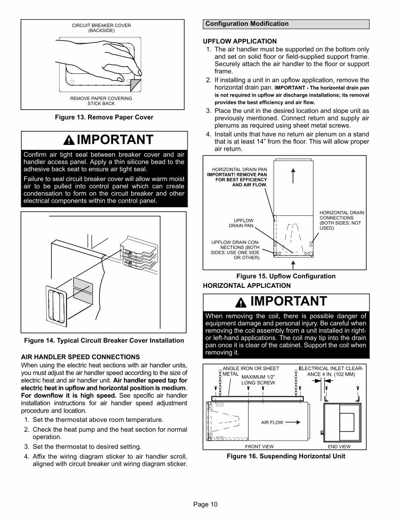
Refer to figure 31 for typical low voltage field wiring for airhandler/condensing unit and heat pump applications.Figure 32 is a diagram of the air handler connections andthe heater elements high-voltage wiring.
1. Make wiring connections as follows -
Heaters equipped with circuit breakers—Connect
field power supply wiring to circuit breaker(s). Figure 11
shows L1, L2 and ground GND connections for a
2-breaker configuration.
ON
OF
F
60
ON
OF
F
60
Figure 11. Field Power Supply Wiring
L1
L2
CIRCUIT 1
L1
L2
CIRCUIT 2
GND 208/240 VOLT FIELDSUPPLY WIRES
Field Supply
Ground Wires
Heaters equipped with terminal blocks—Connect
field power supply wiring to terminal block(s).Figure 12
shows L1, L2 and ground (GND) connection for a
terminal block configuration.
Figure 12. Terminal Block Connections
L1
L2GND
208/240 VOLT FIELDSUPPLY WIRES
FIELD SUPPLYGROUND WIRES
2. Remove the interface harness from the air handler unitand connect the 6-pin connector on the heaterassembly to the mating connector on the air handlerunit.
3. For applications using a two‐stage room thermostatand/or an outdoor thermostat, connect wiring as shownin figure 31.
CIRCUIT BREAKER COVER INSTALLATION
1. Remove any installed patch plates still present .
2. Remove paper covering adhesive back aroundbackside perimeter of circuit breaker cover (figure 13).
3. Position the breaker cover over the air handler circuitbreaker opening (figure 14).
Page 10
CIRCUIT BREAKER COVER(BACKSIDE)
REMOVE PAPER COVERINGSTICK BACK
Figure 13. Remove Paper Cover
IMPORTANTConfirm air tight seal between breaker cover and airhandler access panel. Apply a thin silicone bead to theadhesive back seat to ensure air tight seal.
Failure to seal circuit breaker cover will allow warm moistair to be pulled into control panel which can createcondensation to form on the circuit breaker and otherelectrical components within the control panel.
Figure 14. Typical Circuit Breaker Cover Installation
AIR HANDLER SPEED CONNECTIONS
When using the electric heat sections with air handler units,you must adjust the air handler speed according to the size ofelectric heat and air handler unit. Air handler speed tap forelectric heat in upflow and horizontal position is medium.For downflow it is high speed. See specific air handlerinstallation instructions for air handler speed adjustmentprocedure and location.
1. Set the thermostat above room temperature.
2. Check the heat pump and the heat section for normaloperation.
3. Set the thermostat to desired setting.
4. Affix the wiring diagram sticker to air handler scroll,aligned with circuit breaker unit wiring diagram sticker.
Configuration Modification
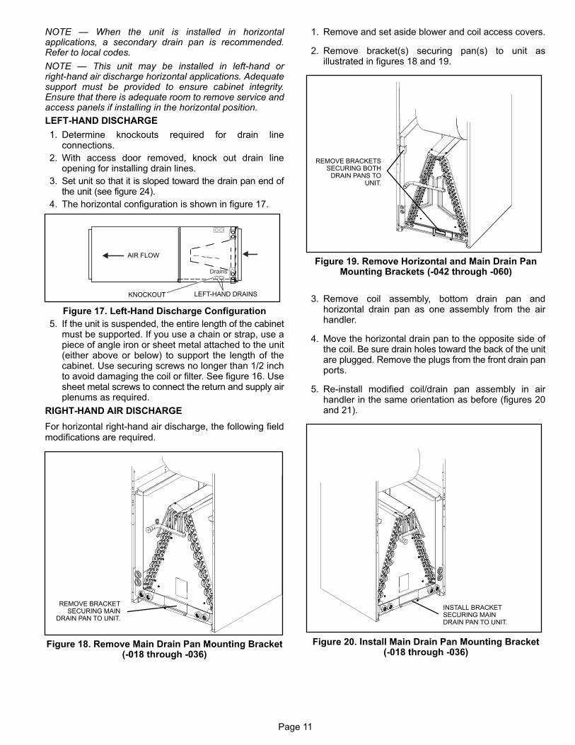
UPFLOW APPLICATION
1. The air handler must be supported on the bottom onlyand set on solid floor or field‐supplied support frame.Securely attach the air handler to the floor or supportframe.
2. If installing a unit in an upflow application, remove thehorizontal drain pan. IMPORTANT - The horizontal drain pan
is not required in upflow air discharge installations; its removal
provides the best efficiency and air flow.
3. Place the unit in the desired location and slope unit aspreviously mentioned. Connect return and supply airplenums as required using sheet metal screws.
4. Install units that have no return air plenum on a standthat is at least 14” from the floor. This will allow properair return.
HORIZONTAL DRAIN PANIMPORTANT! REMOVE PAN
FOR BEST EFFICIENCYAND AIR FLOW.
UPFLOWDRAIN PAN
UPFLOW DRAIN CONNECTIONS (BOTH
SIDES; USE ONE SIDEOR OTHER)
HORIZONTAL DRAINCONNECTIONS(BOTH SIDES; NOTUSED)
Figure 15. Upflow Configuration
HORIZONTAL APPLICATION
IMPORTANTWhen removing the coil, there is possible danger ofequipment damage and personal injury. Be careful whenremoving the coil assembly from a unit installed in right-or left-hand applications. The coil may tip into the drainpan once it is clear of the cabinet. Support the coil whenremoving it.
FRONT VIEW END VIEW
ANGLE IRON OR SHEETMETAL
ELECTRICAL INLET CLEAR
ANCE 4 IN. (102 MM)MAXIMUM 1/2”
LONG SCREW
AIR FLOW
Figure 16. Suspending Horizontal Unit
Page 11
NOTE — When the unit is installed in horizontalapplications, a secondary drain pan is recommended.Refer to local codes.
NOTE — This unit may be installed in left-hand orright-hand air discharge horizontal applications. Adequatesupport must be provided to ensure cabinet integrity.Ensure that there is adequate room to remove service andaccess panels if installing in the horizontal position.
LEFT-HAND DISCHARGE
1. Determine knockouts required for drain lineconnections.
2. With access door removed, knock out drain lineopening for installing drain lines.
3. Set unit so that it is sloped toward the drain pan end ofthe unit (see figure 24).
4. The horizontal configuration is shown in figure 17.
Drains
AIR FLOW
KNOCKOUT LEFT‐HAND DRAINS
Figure 17. Left‐Hand Discharge Configuration
5. If the unit is suspended, the entire length of the cabinetmust be supported. If you use a chain or strap, use apiece of angle iron or sheet metal attached to the unit(either above or below) to support the length of thecabinet. Use securing screws no longer than 1/2 inchto avoid damaging the coil or filter. See figure 16. Usesheet metal screws to connect the return and supply airplenums as required.
RIGHT-HAND AIR DISCHARGE
For horizontal right-hand air discharge, the following fieldmodifications are required.
REMOVE BRACKETSECURING MAIN
DRAIN PAN TO UNIT.
Figure 18. Remove Main Drain Pan Mounting Bracket(-018 through -036)
1. Remove and set aside blower and coil access covers.
2. Remove bracket(s) securing pan(s) to unit asillustrated in figures 18 and 19.
REMOVE BRACKETSSECURING BOTH
DRAIN PANS TOUNIT.
Figure 19. Remove Horizontal and Main Drain PanMounting Brackets (-042 through -060)
3. Remove coil assembly, bottom drain pan andhorizontal drain pan as one assembly from the airhandler.
4. Move the horizontal drain pan to the opposite side ofthe coil. Be sure drain holes toward the back of the unitare plugged. Remove the plugs from the front drain panports.
5. Re-install modified coil/drain pan assembly in airhandler in the same orientation as before (figures 20and 21).
INSTALL BRACKETSECURING MAINDRAIN PAN TO UNIT.
Figure 20. Install Main Drain Pan Mounting Bracket(-018 through -036)
Page 12
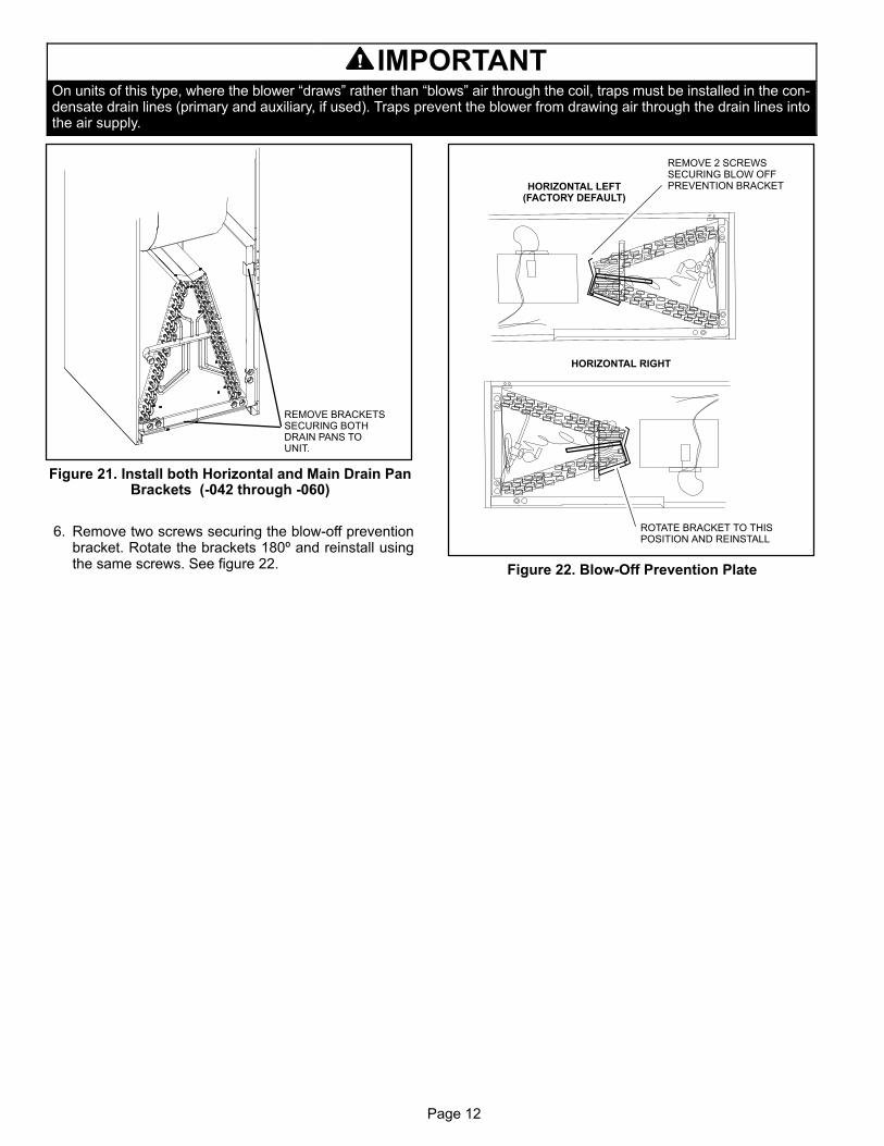
IMPORTANTOn units of this type, where the blower “draws” rather than “blows” air through the coil, traps must be installed in the condensate drain lines (primary and auxiliary, if used). Traps prevent the blower from drawing air through the drain lines intothe air supply.
REMOVE BRACKETSSECURING BOTHDRAIN PANS TOUNIT.
Figure 21. Install both Horizontal and Main Drain PanBrackets (-042 through -060)
6. Remove two screws securing the blow-off preventionbracket. Rotate the brackets 180º and reinstall usingthe same screws. See figure 22.
ROTATE BRACKET TO THISPOSITION AND REINSTALL
REMOVE 2 SCREWSSECURING BLOW OFFPREVENTION BRACKETHORIZONTAL LEFT
(FACTORY DEFAULT)
HORIZONTAL RIGHT
Figure 22. Blow-Off Prevention Plate
Page 13
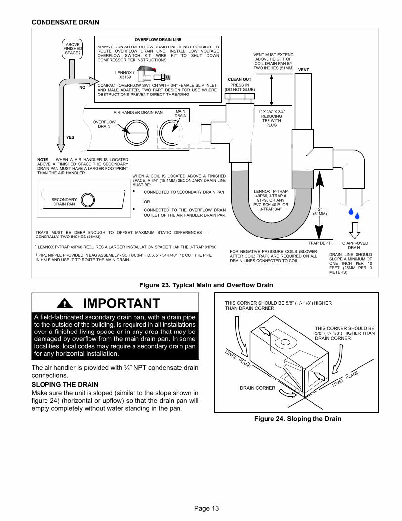
CONDENSATE DRAIN
ABOVEFINISHEDSPACE?
OVERFLOW DRAIN LINE
ALWAYS RUN AN OVERFLOW DRAIN LINE. IF NOT POSSIBLE TOROUTE OVERFLOW DRAIN LINE, INSTALL LOW VOLTAGEOVERFLOW SWITCH KIT. WIRE KIT TO SHUT DOWNCOMPRESSOR PER INSTRUCTIONS.
NO
YES
LENNOX #X3169
CLEAN OUT
VENT
PRESS IN(DO NOT GLUE)
VENT MUST EXTENDABOVE HEIGHT OFCOIL DRAIN PAN BYTWO INCHES (51MM)
1” X 3/4” X 3/4”REDUCINGTEE WITH
PLUG
LENNOX1 P-TRAP49P66, J-TRAP #91P90 OR ANY
PVC SCH 40 P- ORJ-TRAP 3/4”
OVERFLOWDRAIN
AIR HANDLER DRAIN PAN
WHEN A COIL IS LOCATED ABOVE A FINISHEDSPACE, A 3/4” (19.1MM) SECONDARY DRAIN LINEMUST BE:
� CONNECTED TO SECONDARY DRAIN PAN
OR
� CONNECTED TO THE OVERFLOW DRAIN
OUTLET OF THE AIR HANDLER DRAIN PAN.
TRAPS MUST BE DEEP ENOUGH TO OFFSET MAXIMUM STATIC DIFFERENCES —GENERALLY, TWO INCHES (51MM).
DRAIN LINE SHOULDSLOPE A MINIMUM OFONE INCH PER 10FEET (25MM PER 3METERS)
NOTE — WHEN A AIR HANDLER IS LOCATEDABOVE A FINISHED SPACE THE SECONDARYDRAIN PAN MUST HAVE A LARGER FOOTPRINTTHAN THE AIR HANDLER.
MAINDRAIN
TO APPROVEDDRAIN
FOR NEGATIVE PRESSURE COILS (BLOWERAFTER COIL) TRAPS ARE REQUIRED ON ALLDRAIN LINES CONNECTED TO COIL.
COMPACT OVERFLOW SWITCH WITH 3/4” FEMALE SLIP INLETAND MALE ADAPTER, TWO PART DESIGN FOR USE WHEREOBSTRUCTIONS PREVENT DIRECT THREADING
SECONDARYDRAIN PAN
2”(51MM)
TRAP DEPTH1 LENNOX P-TRAP 49P66 REQUIRES A LARGER INSTALLATION SPACE THAN THE J-TRAP 91P90.
2 PIPE NIPPLE PROVIDED IN BAG ASSEMBLY - SCH 80, 3/4” I. D. X 5” - 34K7401 (1): CUT THE PIPEIN HALF AND USE IT TO ROUTE THE MAIN DRAIN.
Figure 23. Typical Main and Overflow Drain
IMPORTANTA field-fabricated secondary drain pan, with a drain pipeto the outside of the building, is required in all installationsover a finished living space or in any area that may bedamaged by overflow from the main drain pan. In somelocalities, local codes may require a secondary drain panfor any horizontal installation.
The air handler is provided with ¾” NPT condensate drainconnections.
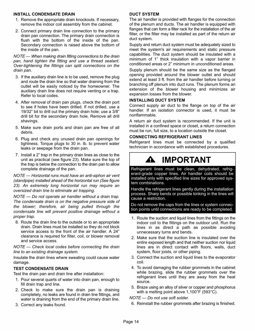
SLOPING THE DRAIN
Make sure the unit is sloped (similar to the slope shown infigure 24) (horizontal or upflow) so that the drain pan willempty completely without water standing in the pan.
THIS CORNER SHOULD BE 5/8” (+/- 1/8”) HIGHERTHAN DRAIN CORNER
DRAIN CORNER
THIS CORNER SHOULD BE 5/8” (+/- 1/8”) HIGHER THANDRAIN CORNER
Figure 24. Sloping the Drain
Page 14
INSTALL CONDENSATE DRAIN
1. Remove the appropriate drain knockouts. If necessary,remove the indoor coil assembly from the cabinet.
2. Connect primary drain line connection to the primarydrain pan connection. The primary drain connection isflush with the bottom of the inside of the pan.Secondary connection is raised above the bottom ofthe inside of the pan.
NOTE — When making drain fitting connections to the drainpan, hand tighten the fitting and use a thread sealant.Over-tightening the fittings can split connections on thedrain pan.
3. If the auxiliary drain line is to be used, remove the plugand route the drain line so that water draining from theoutlet will be easily noticed by the homeowner. Theauxiliary drain line does not require venting or a trap.Refer to local codes.
4. After removal of drain pan plugs, check the drain portto see if holes have been drilled. If not drilled, use a19/32” bit to drill out the primary drain hole; use a 3/8”drill bit for the secondary drain hole. Remove all drillshavings.
5. Make sure drain ports and drain pan are free of alldebris.
6. Plug and check any unused drain pan openings fortightness. Torque plugs to 30 in. lb. to prevent waterleaks or seepage from the drain pan.
7. Install a 2” trap in the primary drain lines as close to theunit as practical (see figure 23). Make sure the top ofthe trap is below the connection to the drain pan to allowcomplete drainage of the pan.
NOTE — Horizontal runs must have an anti-siphon air vent
(standpipe) installed ahead of the horizontal run (See figure
23). An extremely long horizontal run may require an
oversized drain line to eliminate air trapping.
NOTE — Do not operate air handler without a drain trap.
The condensate drain is on the negative pressure side of
the blower; therefore, air being pulled through the
condensate line will prevent positive drainage without a
proper trap.
8. Route the drain line to the outside or to an appropriatedrain. Drain lines must be installed so they do not blockservice access to the front of the air handler. A 24”clearance is required for filter, coil, or blower removaland service access.
NOTE — Check local codes before connecting the drain
line to an existing drainage system.
Insulate the drain lines where sweating could cause waterdamage.
TEST CONDENSATE DRAIN
Test the drain pan and drain line after installation:
1. Pour several quarts of water into drain pan, enough tofill drain trap and line.
2. Check to make sure the drain pan is drainingcompletely, no leaks are found in drain line fittings, andwater is draining from the end of the primary drain line.
3. Correct any leaks found.
DUCT SYSTEM
The air handler is provided with flanges for the connectionof the plenum and ducts. The air handler is equipped withflanges that can form a filter rack for the installation of the airfilter, or the filter may be installed as part of the return airduct system.
Supply and return duct system must be adequately sized tomeet the system's air requirements and static pressurecapabilities. The duct system should be insulated with aminimum of 1” thick insulation with a vapor barrier inconditioned areas or 2” minimum in unconditioned areas.
Supply plenum should be the same size as the flangedopening provided around the blower outlet and shouldextend at least 3 ft. from the air handler before turning orbranching off plenum into duct runs. The plenum forms anextension of the blower housing and minimizes airexpansion losses from the blower.
INSTALLING DUCT SYSTEM
Connect supply air duct to the flange on top of the airhandler. If an isolation connector is used, it must benonflammable.
A return air duct system is recommended. If the unit isinstalled in a confined space or closet, a return connectionmust be run, full size, to a location outside the closet.
CONNECTING REFRIGERANT LINES
Refrigerant lines must be connected by a qualifiedtechnician in accordance with established procedures.
IMPORTANTRefrigerant lines must be clean, dehydrated, refrigerant-grade copper lines. Air handler coils should beinstalled only with specified line sizes for approved system combinations.
Handle the refrigerant lines gently during the installationprocess. Sharp bends or possible kinking in the lines willcause a restriction.
Do not remove the caps from the lines or system connection points until connections are ready to be completed.
1. Route the suction and liquid lines from the fittings on theindoor coil to the fittings on the outdoor unit. Run thelines in as direct a path as possible avoidingunnecessary turns and bends.
2. Make sure that the suction line is insulated over theentire exposed length and that neither suction nor liquidlines are in direct contact with floors, walls, ductsystem, floor joists, or other piping.
3. Connect the suction and liquid lines to the evaporatorcoil.
4. To avoid damaging the rubber grommets in the cabinetwhile brazing, slide the rubber grommets over therefrigerant lines until they are away from the heatsource.
5. Braze using an alloy of silver or copper and phosphoruswith a melting point above 1,100°F (593°C).
NOTE — Do not use soft solder.
6. Reinstall the rubber grommets after brazing is finished.
Page 15
7. Make sure outdoor unit has been put in place accordingto the Installation Instructions and is connected to therefrigerant lines.
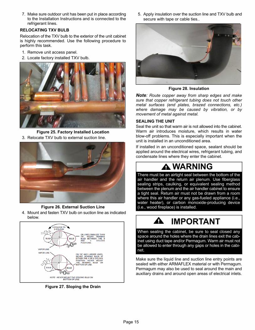
RELOCATING TXV BULB
Relocation of the TXV bulb to the exterior of the unit cabinetis highly recommended. Use the following procedure toperform this task.
1. Remove unit access panel.
2. Locate factory installed TXV bulb.
Figure 25. Factory Installed Location
3. Relocate TXV bulb to external suction line.
Figure 26. External Suction Line
4. Mount and fasten TXV bulb on suction line as indicatedbelow.
Figure 27. Sloping the Drain
5. Apply insulation over the suction line and TXV bulb and
secure with tape or cable ties..
Figure 28. Insulation
Note: Route copper away from sharp edges and makesure that copper refrigerant tubing does not touch othermetal surfaces (end plates, brazed connections, etc.)where damage may be caused by vibration, or bymovement of metal against metal.
SEALING THE UNIT
Seal the unit so that warm air is not allowed into the cabinet.Warm air introduces moisture, which results in waterblow-off problems. This is especially important when theunit is installed in an unconditioned area.
If installed in an unconditioned space, sealant should beapplied around the electrical wires, refrigerant tubing, andcondensate lines where they enter the cabinet.
WARNINGThere must be an airtight seal between the bottom of theair handler and the return air plenum. Use fiberglasssealing strips, caulking, or equivalent sealing methodbetween the plenum and the air handler cabinet to ensurea tight seal. Return air must not be drawn from a roomwhere this air handler or any gas-fueled appliance (i.e.,water heater), or carbon monoxide-producing device(i.e., wood fireplace) is installed.
IMPORTANTWhen sealing the cabinet, be sure to seal closed anyspace around the holes where the drain lines exit the cabinet using duct tape and/or Permagum. Warm air must notbe allowed to enter through any gaps or holes in the cabinet.
Make sure the liquid line and suction line entry points aresealed with either ARMAFLEX material or with Permagum.Permagum may also be used to seal around the main andauxiliary drains and around open areas of electrical inlets.
Page 16
Electrical Connections
WARNINGElectric shock hazard! - Disconnect allpower supplies before servicing.
Replace all parts and panels before operating.
Failure to do so can result in death or electrical shock.
WARNINGElectric Shock Hazard.
Can cause injury or death.
Foil‐faced insulation has conductive characteristics similar to metal. Be sure there are no electrical connectionswithin a ½” of the insulation. If the foil‐faced insulationcomes in contact with electrical voltage, the foil could provide a path for current to pass through to the outer metalcabinet. While the current produced may not be enoughto trip existing electrical safety devices (e.g. fuses or circuit breakers), the current can be enough to cause anelectric shock hazard that could cause personal injury ordeath.
� All field wiring must be done in accordance with
National Electrical Code, applicable requirements ofUL and local codes, where applicable.
� Electrical wiring, disconnect means and over-current
protection are to be supplied by the installer. Refer tothe air handler rating plate for maximum over-currentprotection, minimum circuit ampacity, as well asoperating voltage.
� The power supply must be sized and protected
according to the specifications supplied on the product.
� This air handler is factory-configured for 240 volt, single
phase, 60 cycles. For 208-volt applications, see “208Volt Conversion” later in this section.
� For optional field‐installed electric heat applications,
refer to the instructions provided with the accessory forproper installation.
WARNINGUSE COPPER CONDUCTORS ONLY
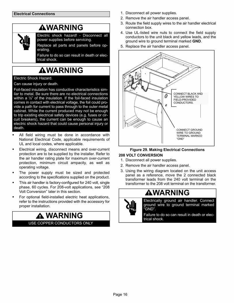
1. Disconnect all power supplies.
2. Remove the air handler access panel.
3. Route the field supply wires to the air handler electricalconnection box.
4. Use UL-listed wire nuts to connect the field supplyconductors to the unit black and yellow leads, and theground wire to ground terminal marked GND.
5. Replace the air handler access panel.
CONNECT BLACK ANDYELLOW WIRES TOFIELD-PROVIDEDCONDUCTORS.
CONNECT GROUNDWIRE TO GROUNDTERMINAL MARKED“GND”
Figure 29. Making Electrical Connections
208 VOLT CONVERSION
1. Disconnect all power supplies.
2. Remove the air handler access panel.
3. Using the wiring diagram located on the unit accesspanel as a reference, move the 2 connected blacktransformer leads from the 240 volt terminal on thetransformer to the 208 volt terminal on the transformer.
WARNINGElectrically ground air handler. Connectground wire to ground terminal marked“GND”.
Failure to do so can result in death or electrical shock.
Page 17
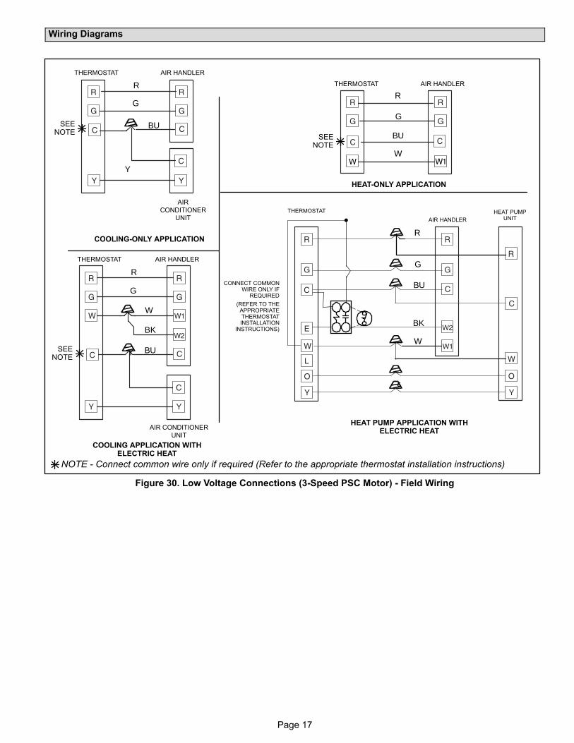
Wiring Diagrams
R
G
AIR
CONDITIONER
UNIT
R
R
G
G
BU
W
W
BK
COOLING‐ONLY APPLICATION
AIR HANDLERTHERMOSTAT
HEAT‐ONLY APPLICATION
AIR HANDLERTHERMOSTAT
COOLING APPLICATION WITHELECTRIC HEAT
AIR HANDLERTHERMOSTAT
HEAT PUMP APPLICATION WITHELECTRIC HEAT
NOTE - Connect common wire only if required (Refer to the appropriate thermostat installation instructions)
BUBU
SEENOTE
SEENOTE
SEENOTE
Y
Y
AIR CONDITIONER
UNIT
R
G
BU
W
BK
CONNECT COMMONWIRE ONLY IF
REQUIRED
(REFER TO THEAPPROPRIATETHERMOSTATINSTALLATION
INSTRUCTIONS)
AIR HANDLER
THERMOSTAT HEAT PUMPUNIT
Figure 30. Low Voltage Connections (3-Speed PSC Motor) - Field Wiring
Page 18
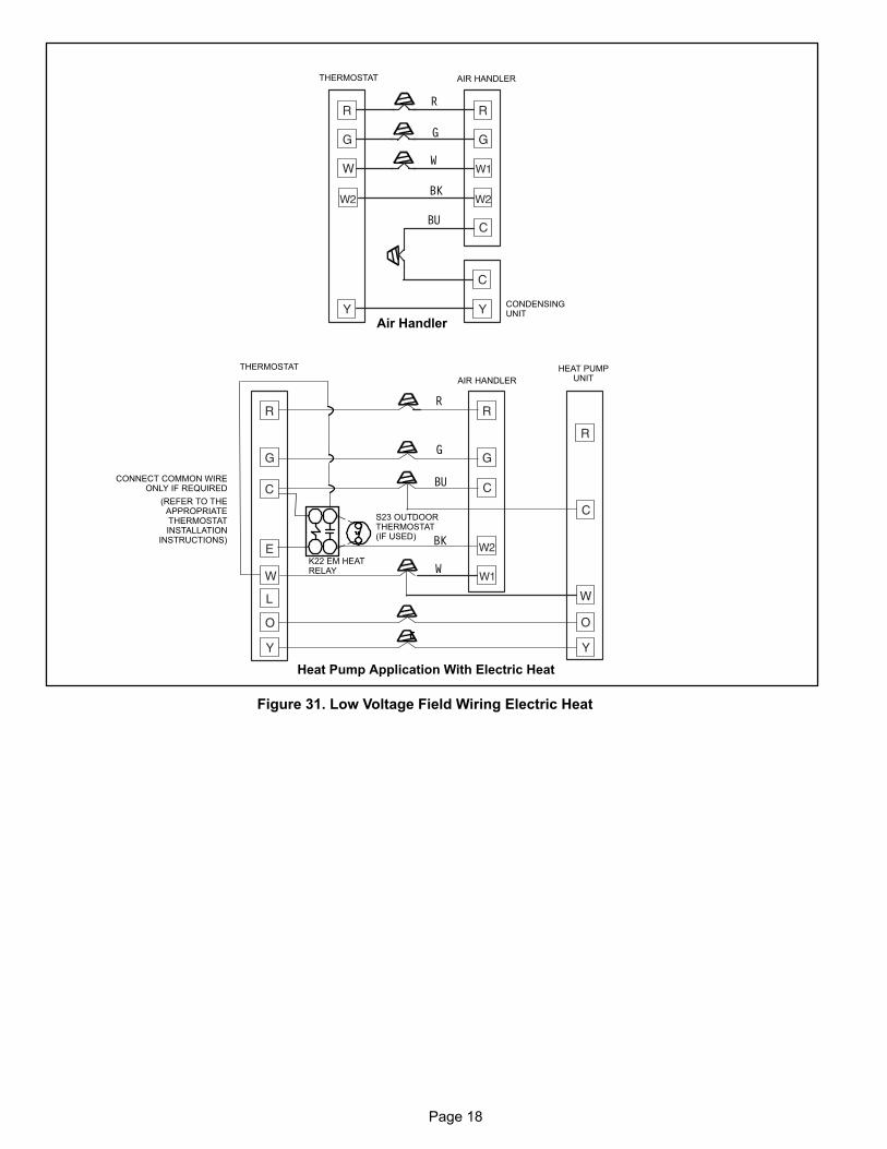
Figure 31. Low Voltage Field Wiring Electric Heat
R
R
G
G
BU
BU
W
W
BK
BK
CONNECT COMMON WIREONLY IF REQUIRED
(REFER TO THEAPPROPRIATETHERMOSTATINSTALLATION
INSTRUCTIONS)
CONDENSINGUNIT
Air Handler
AIR HANDLERTHERMOSTAT
Heat Pump Application With Electric Heat
AIR HANDLER
THERMOSTAT HEAT PUMPUNIT
S23 OUTDOORTHERMOSTAT(IF USED)
K22 EM HEATRELAY
Page 19
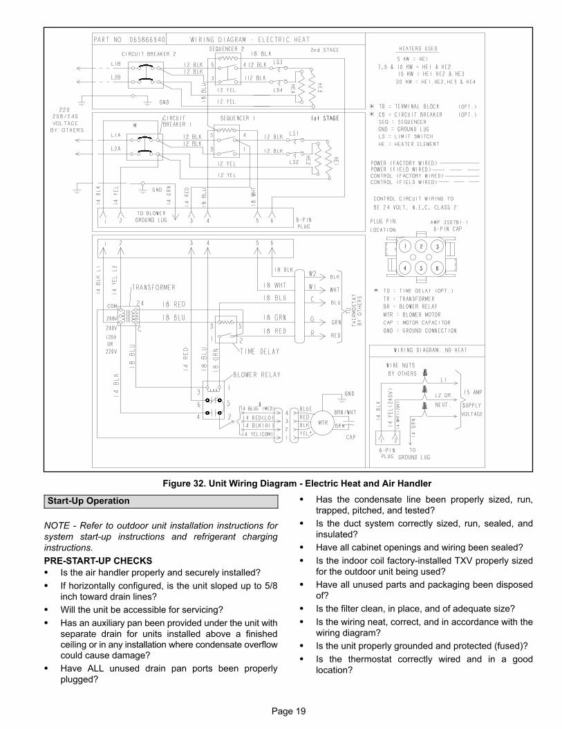
Figure 32. Unit Wiring Diagram - Electric Heat and Air Handler
Start-Up Operation
NOTE - Refer to outdoor unit installation instructions for
system start-up instructions and refrigerant charging
instructions.
PRE‐START‐UP CHECKS
� Is the air handler properly and securely installed?
� If horizontally configured, is the unit sloped up to 5/8
inch toward drain lines?
� Will the unit be accessible for servicing?
� Has an auxiliary pan been provided under the unit with
separate drain for units installed above a finishedceiling or in any installation where condensate overflowcould cause damage?
� Have ALL unused drain pan ports been properly
plugged?
� Has the condensate line been properly sized, run,
trapped, pitched, and tested?
� Is the duct system correctly sized, run, sealed, and
insulated?
� Have all cabinet openings and wiring been sealed?
� Is the indoor coil factory‐installed TXV properly sized
for the outdoor unit being used?
� Have all unused parts and packaging been disposed
of?
� Is the filter clean, in place, and of adequate size?
� Is the wiring neat, correct, and in accordance with the
wiring diagram?
� Is the unit properly grounded and protected (fused)?
� Is the thermostat correctly wired and in a good
location?
Page 20
� Are all access panels in place and secure?
CHECK BLOWER OPERATION
� Set thermostat to FAN ON.
� The indoor blower should come on.
CHECK COOLING OPERATION
� Set thermostat to force a call for cooling (approximately
5ºF lower than the indoor ambient temperature).
� The outdoor and indoor units should come on
immediately.
� Check the airflow from a register to confirm that the
system is moving cooled air.
� Set the thermostat 5ºF higher than the indoor
temperature. The indoor blower and outdoor unitshould cycle off. Air handler should cycle off 45seconds after the outdoor unit shuts off.
CHECK ELECTRIC HEATER (IF USED)
� Set thermostat to call for auxiliary heat (approximately
5°F above ambient temperature). The indoor blowerand auxiliary heat should come on together. Allow aminimum of 3 minutes for all sequencers to cycle on.
� Set the thermostat so that it does not call for heat. Allow
up to 5 minutes for all sequencers to cycle off.
Sequence of Operation
COOLING (COOLING ONLY OR HEAT PUMP)
When the thermostat calls for cooling, 24 volts is put on theblower time-delay relay coil and then the indoor blowerrelay energizes. The normally open contacts close, causingthe indoor blower motor to operate. The circuit between Rand Y is completed, closing the circuit to the contactor in theoutdoor unit, starting the compressor and outdoor fanmotor.
On heat pumps, circuit R and O energizes the reversingvalve, switching the valve to the cooling position. (Thereversing valve remains energized as long as thethermostat selector switch is in the COOL position.)
At the completion of the cooling demand the indoor blowerand outdoor unit should cycle off. Air handler should cycleoff 45 seconds after the outdoor unit shuts off.
HEATING (ELECTRIC HEAT ONLY)
When the thermostat calls for heat, the circuit between Rand W is completed, and the heat sequencer is energized.A time delay follows before the heating elements and theindoor blower motor come on. Units with a second heatsequencer can be connected with the first sequencer to Won the thermostat subbase, or they may also be connectedto a second stage on the subbase.
HEATING (HEAT PUMP)
When the thermostat calls for heating, 24 volts is put on theblower time-delay relay coil. Then normally open contactsclose, causing the indoor blower motor to operate. Thecircuit between R and Y is completed, closing the circuit tothe contactor in the outdoor unit, starting the compressorand outdoor fan motor.
If the room temperature should continue to fall, the circuitbetween R and W1 is completed by the second‐stage heatroom thermostat. Circuit R-W1 energizes a heatsequencer. The completed circuit will energizesupplemental electric heat (if applicable). Units with asecond heat sequencer can be connected with the firstsequencer to W1 on the thermostat. They may also beconnected to a second heating stage W2 on the thermostatsubbase.
EMERGENCY HEAT (HEATING HEAT PUMP)
If the selector switch on the thermostat is set to theemergency heat position, the heat pump will be locked outof the heating circuit, and all heating will be electric heat (ifapplicable). A jumper should be placed between W2 and Eon the thermostat subbase so that the electric heat controlwill transfer to the first‐stage heat on the thermostat. Thiswill allow the indoor blower to cycle on and off with theelectric heat when the fan switch is in the AUTO position.
Page 21
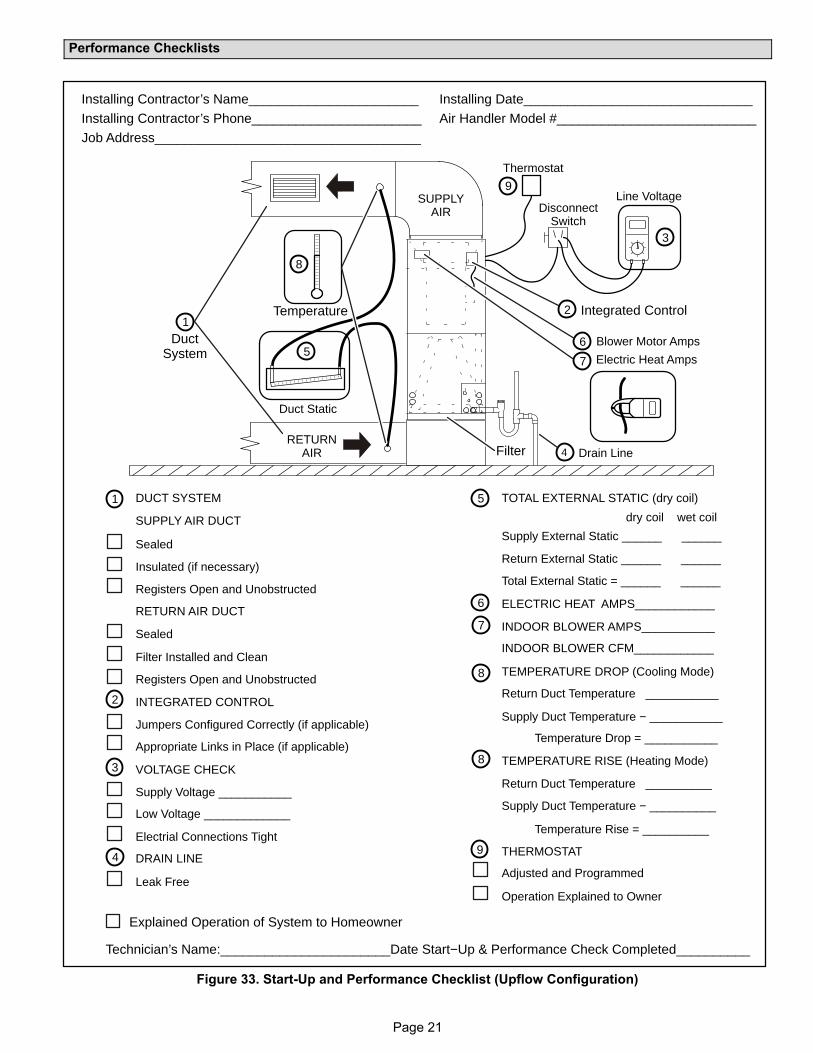
Performance Checklists
1Duct
System
Filter
Integrated Control
Electric Heat Amps
Duct Static
5
Line Voltage
3
RETURNAIR
SUPPLYAIR
Temperature
8
Blower Motor Amps6
7
Thermostat
9
2
4 Drain Line
DisconnectSwitch
ELECTRIC HEAT AMPS____________
8
8
7
5DUCT SYSTEM
SUPPLY AIR DUCT
Sealed
Insulated (if necessary)
Registers Open and Unobstructed
RETURN AIR DUCT
Sealed
Filter Installed and Clean
Registers Open and Unobstructed
INTEGRATED CONTROL
Jumpers Configured Correctly (if applicable)
Appropriate Links in Place (if applicable)
VOLTAGE CHECK
Supply Voltage ___________
Electrial Connections Tight
1
2
3
DRAIN LINE
Leak Free
4
TOTAL EXTERNAL STATIC (dry coil)
Supply External Static ______ ______
TEMPERATURE DROP (Cooling Mode)
Return Duct Temperature ___________
THERMOSTAT
Adjusted and Programmed
Return External Static ______ ______
Total External Static = ______ ______
6
Supply Duct Temperature − ___________
Temperature Drop = ___________
TEMPERATURE RISE (Heating Mode)
Return Duct Temperature __________
Supply Duct Temperature − __________
Temperature Rise = __________
Operation Explained to Owner
9
Explained Operation of System to Homeowner
Technician’s Name:_______________________Date Start−Up & Performance Check Completed__________
Installing Contractor’s Name_______________________
Installing Contractor’s Phone_______________________
Job Address____________________________________
Installing Date_______________________________
Air Handler Model #___________________________
INDOOR BLOWER AMPS___________
INDOOR BLOWER CFM____________
Low Voltage _____________
dry coil wet coil
Figure 33. Start-Up and Performance Checklist (Upflow Configuration)
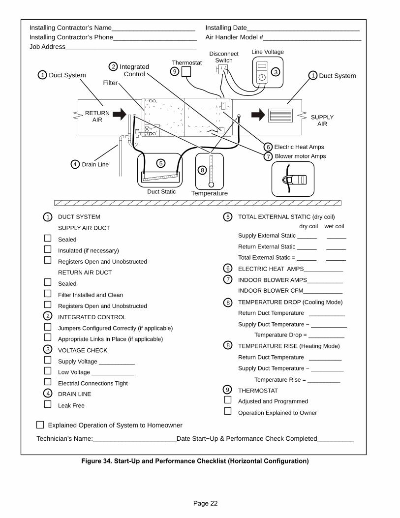
Page 22
RETURNAIR SUPPLY
AIR
2
Duct Static
5
Line Voltage
3
4 Drain Line
ELECTRIC HEAT AMPS____________
8
8
7
5
Filter
Blower motor Amps
DUCT SYSTEM
SUPPLY AIR DUCT
Sealed
Insulated (if necessary)
Registers Open and Unobstructed
RETURN AIR DUCT
Sealed
Filter Installed and Clean
Registers Open and Unobstructed
INTEGRATED CONTROL
Jumpers Configured Correctly (if applicable)
Appropriate Links in Place (if applicable)
VOLTAGE CHECK
Supply Voltage ___________
Electrial Connections Tight
1
2
3
DRAIN LINE
Leak Free
4
TOTAL EXTERNAL STATIC (dry coil)
Supply External Static ______ ______
TEMPERATURE DROP (Cooling Mode)
Return Duct Temperature ___________
THERMOSTAT
Adjusted and Programmed
Return External Static ______ ______
Total External Static = ______ ______
6
6
Supply Duct Temperature − ___________
Temperature Drop = ___________
TEMPERATURE RISE (Heating Mode)
Return Duct Temperature __________
Supply Duct Temperature − __________
Temperature Rise = __________
Operation Explained to Owner
9
Electric Heat Amps
7
Explained Operation of System to Homeowner
Technician’s Name:_______________________Date Start−Up & Performance Check Completed__________
Installing Contractor’s Name_______________________
Installing Contractor’s Phone_______________________
Job Address____________________________________
Installing Date_______________________________
Air Handler Model #___________________________
Thermostat
91 1
8
INDOOR BLOWER AMPS___________
Temperature
Duct SystemDuct SystemIntegrated
Control
DisconnectSwitch
INDOOR BLOWER CFM____________
Low Voltage _____________
dry coil wet coil
Figure 34. Start-Up and Performance Checklist (Horizontal Configuration)