corevalve ® msct scan acquisition and processing march 2013 innovating for life. uc201305577 ee
TRANSCRIPT

CoreValve® MSCT Scan Acquisition and Processing
March 2013
Innovating for life.UC201305577 EE

AcademiaMedical Education
INTERNATIONAL. CAUTION: For distribution only in markets where CoreValve® is approved. Not for distribution in U.S. or Japan. Medtronic, Inc. 2013. All Rights Reserved.
The MSCT Sizing Process
The sizing process includes three main parts, all of equal importance:
– Proper image acquisition and post-processing– Reformatting of the aortic root and preparation for
measurement– Aortic root measurements and device selection
(covered earlier in presentation)

AcademiaMedical Education
INTERNATIONAL. CAUTION: For distribution only in markets where CoreValve® is approved. Not for distribution in U.S. or Japan. Medtronic, Inc. 2013. All Rights Reserved.
MSCT Scan Acquisition

AcademiaMedical Education
INTERNATIONAL. CAUTION: For distribution only in markets where CoreValve® is approved. Not for distribution in U.S. or Japan. Medtronic, Inc. 2013. All Rights Reserved.
Multi-detector CT scanner (64-slice minimum) with ECG-gating capability.
– The scans of the aortic root MUST be ECG-gated.Non-gated scans in areas with cardiac motion lead to measurement inaccuracy and therefore incomplete information for device selection.
– Peripheral vessel image acquisition may be non-gated.
Post-processing software capable of MPR and standard measurements (diameter, area, perimeter)
– This is typically standard on most imaging system workstations
– This is also available on many second party applications
Equipment Required

AcademiaMedical Education
INTERNATIONAL. CAUTION: For distribution only in markets where CoreValve® is approved. Not for distribution in U.S. or Japan. Medtronic, Inc. 2013. All Rights Reserved.
1. Chest topogram2. ECG-gated contrast enhanced aortic root3. Non ECG-gated contrast enhanced peripheral
vessels
Sub-millimeter slice thickness is required for scans 2 and 3
Scans Required

AcademiaMedical Education
INTERNATIONAL. CAUTION: For distribution only in markets where CoreValve® is approved. Not for distribution in U.S. or Japan. Medtronic, Inc. 2013. All Rights Reserved.
• The scan protocol is similar to a CT coronary angiogram.
• The aim is to get adequate contrast in the region of interest (i.e., endo-luminal surface) for visualization of left heart, aorta, and peripheral access vessels (i.e., femorals and subclavians) when necessary.
• Temporal resolution should be optimized to reduce motion artifact.
• Spatial resolution should be as high as possible (goal is smallest isotropic voxel size for high-quality MPR).
Scanning Procedures

AcademiaMedical Education
INTERNATIONAL. CAUTION: For distribution only in markets where CoreValve® is approved. Not for distribution in U.S. or Japan. Medtronic, Inc. 2013. All Rights Reserved.
• Administer medication per institution standard practice for CT scanning.
• Attach ECG electrodes for gating of scan. Verify quality of ECG tracing on scanner console.
• Prepare large intravenous line (18 or 20 gauge) for administration of contrast media.
• Instruct patient to lie still during scan, even if they experience warmth or tingling due to the injection of contrast.
• Instruct patient in practice of breath-hold at end-inspiration for 10-15 seconds (duration required will depend on specific scanner performance). Assess heart rate variability during breath-hold. If heart rate is >65 bpm or unstable, consider titration of beta-blockers.
Step 1: Patient Preparation

AcademiaMedical Education
INTERNATIONAL. CAUTION: For distribution only in markets where CoreValve® is approved. Not for distribution in U.S. or Japan. Medtronic, Inc. 2013. All Rights Reserved.
Acquire a chest topogram for use in planning the imaging protocol.
Step 2: Topogram

AcademiaMedical Education
INTERNATIONAL. CAUTION: For distribution only in markets where CoreValve® is approved. Not for distribution in U.S. or Japan. Medtronic, Inc. 2013. All Rights Reserved.
• Intent: Assessment of aortic root and valve anatomy
• Coverage area – Suggested: Superior to aortic arch - inferior to cardiac
apex– Minimum: 10 mm below aortic annulus – 70 mm above
aortic annulus (includes the aortic root and direct aortic access)
• Retrospective or prospective ECG-gating may be usedReconstruct or trigger in systole
• Required detector collimation of 0.4 – 0.625 mm• Required slice thickness of < 1 mm• Recommended slice overlap of 0.4 mm
Step 3: Contrast Enhanced Scan Parameters

AcademiaMedical Education
INTERNATIONAL. CAUTION: For distribution only in markets where CoreValve® is approved. Not for distribution in U.S. or Japan. Medtronic, Inc. 2013. All Rights Reserved.
Minimum Coverage
Area
Recommended Coverage Area

AcademiaMedical Education
INTERNATIONAL. CAUTION: For distribution only in markets where CoreValve® is approved. Not for distribution in U.S. or Japan. Medtronic, Inc. 2013. All Rights Reserved.
• Prepare iodinated contrast injection apparatus.• Set up scan parameters per the table on slide 17. • Instruct patient to lie still during scan, even if they experience
warmth or tingling due to the injection of contrast. • Initiate contrast injection. • When contrast reaches threshold at bolus-tracking location,
instruct patient to hold breath at end-inspiration, then initiate main scan protocol.
• At completion of scan verify images are of adequate quality.• Record amount of contrast given. • Record heart rate average and range.
Step 3: ECG-Gated, Contrast Enhanced Scan Execution

AcademiaMedical Education
INTERNATIONAL. CAUTION: For distribution only in markets where CoreValve® is approved. Not for distribution in U.S. or Japan. Medtronic, Inc. 2013. All Rights Reserved.
• Verify heart rate ECG triggers are at consistent place in cardiac cycle, edit if necessary. Additional editing/removal of arrhythmias may be performed.
• If retrospective gating is used: – Reconstruct the cleanest systolic phase from a signal-noise ratio and motion
artifact perspective. – Automated “best-systolic” reconstruction can also be used.– < 1 mm slice thickness with small overlap
Step 4: Post-processing of Aortic Root Images

AcademiaMedical Education
INTERNATIONAL. CAUTION: For distribution only in markets where CoreValve® is approved. Not for distribution in U.S. or Japan. Medtronic, Inc. 2013. All Rights Reserved.
ECG-Gated, Contrast Enhanced Scan Parameters Recommended Parameters
IV injection with iodine contrast
80-100 (320mg/ml or higher), modify per patient as appropriate
Injection rate 4-6 mL/sec
Bolus tracking, delay Delay time calculated using protocol for current scanner (bolus tracking or similar) with peak of contrast concentration in the ascending aorta during acquisition.
ECG Leads Required
ECG-gating Prospective or Retrospective
Scan direction Cranial-caudal
Scan coverage From above the aortic arch to past the cardiac apex
Detector collimation 0.4 – 0.625 mm
Pitch 0.2–0.43 adapted to the heart rate
Dose modulation If retrospective, modulation and full current between 30 and 80% of the cardiac cycle
Slice thickness 0.8 mm
Slice overlap 0.4 mm
Reconstruction kernel Medium Smooth
Post-processing Reconstruct the cleanest systolic phase from a signal-noise ratio and motion artifact perspective.
Automated “best-systolic” reconstruction can also be used.
Reconstructed slice thickness <1 mm.

AcademiaMedical Education
INTERNATIONAL. CAUTION: For distribution only in markets where CoreValve® is approved. Not for distribution in U.S. or Japan. Medtronic, Inc. 2013. All Rights Reserved.
• Intent: Assessment of peripheral access vessels• Standard radiology CT angiography protocol• Non ECG-gated• Delay time calculated using protocol for current scanner (i.e.,
bolus tracking) with peak of contrast concentration in the area of interest
• Suggested coverage areas: – Femoral access only screening: abdominal aorta above celiac artery
and down to the femoral head– Subclavian access only screening: above the subclavian arteries and
down to mid-thorax– Combined access screening: above the subclavian arteries and down
to the femoral head• Source data reconstructed using < 1 mm slice thickness with
small overlap
Step 5: Non-gated, Contrast-Enhanced Scan of the Peripheral Access Vessels

AcademiaMedical Education
INTERNATIONAL. CAUTION: For distribution only in markets where CoreValve® is approved. Not for distribution in U.S. or Japan. Medtronic, Inc. 2013. All Rights Reserved.
MSCT Scan Processing
AcademiaMedical Education
INTERNATIONAL. CAUTION: For distribution only in markets where CoreValve® is approved. Not for distribution in U.S. or Japan. Medtronic, Inc. 2013. All Rights Reserved.
• The aortic annulus is not co-planar with the planes of the body (i.e., axial, sagittal, or coronal).
• Therefore, multi-planar reformatting of the CT images is required to create a double-oblique axial image for annulus measurements.
• This reformatting is critical; if the plane is not correctly aligned, it may be passing through the sinuses or the LVOT. This can lead to improper device selection.
• This reformatting is also used in assessing the measurements for the rest of the aortic root (sinus width, height and ascending aorta diameters).
• The following methods are similar to those reported in Schultz et al. EuroIntervention Supplement (2010) Volume 6 (Supplement G) G6-G13.
Proper Aortic Annulus Measurements
AcademiaMedical Education
INTERNATIONAL. CAUTION: For distribution only in markets where CoreValve® is approved. Not for distribution in U.S. or Japan. Medtronic, Inc. 2013. All Rights Reserved.
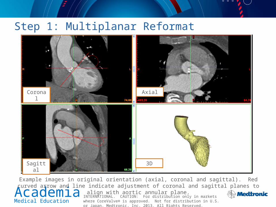
Example images in original orientation (axial, coronal and sagittal). Red curved arrow and line indicate adjustment of coronal and sagittal planes to align with aortic annular plane.
Step 1: Multiplanar Reformat
AxialCoronal
Sagittal 3D

AcademiaMedical Education
INTERNATIONAL. CAUTION: For distribution only in markets where CoreValve® is approved. Not for distribution in U.S. or Japan. Medtronic, Inc. 2013. All Rights Reserved.
Step 2: Verify Aortic Annular Plane
Example images of reformatted oblique coronal (upper left), oblique sagittal (lower left), double oblique (upper right) and 3D reconstruction (lower right). Yellow triangles indicate most basal attachment points of the aortic valve.
Double Oblique
AxialOblique Coronal
Oblique Sagittal 3D

AcademiaMedical Education
INTERNATIONAL. CAUTION: For distribution only in markets where CoreValve® is approved. Not for distribution in U.S. or Japan. Medtronic, Inc. 2013. All Rights Reserved.
The Aortic Annulus on MSCT
Descending Aorta
Aortic Annulus
RVOT
RA
LA
LAA

AcademiaMedical Education
INTERNATIONAL. CAUTION: For distribution only in markets where CoreValve® is approved. Not for distribution in U.S. or Japan. Medtronic, Inc. 2013. All Rights Reserved.
Example of Incorrect Plane – Too Low
Example images of reformatted oblique coronal (upper left), oblique sagittal (lower left), double oblique (upper right) and 3D reconstruction (lower right). The double oblique axial image is located approximately 10 mm into the LVOT.
Double Oblique
AxialOblique Coronal
Oblique Sagittal 3D

AcademiaMedical Education
INTERNATIONAL. CAUTION: For distribution only in markets where CoreValve® is approved. Not for distribution in U.S. or Japan. Medtronic, Inc. 2013. All Rights Reserved.
Example of Incorrect Plane – Too High
Oblique Coronal
Double Oblique
Axial
ObliqueSagittal
Example images of reformatted oblique coronal (upper left), oblique sagittal (lower left), double oblique (upper right) and 3D reconstruction lower right. The double oblique axial image is located a few mm into the aortic root and the leaflets are
visible.
Double Oblique
AxialOblique Coronal
Oblique Sagittal 3D

AcademiaMedical Education
INTERNATIONAL. CAUTION: For distribution only in markets where CoreValve® is approved. Not for distribution in U.S. or Japan. Medtronic, Inc. 2013. All Rights Reserved.
Example of Incorrect Plane – Wrong Orientation
Example images of reformatted oblique coronal (upper left), oblique sagittal (lower left), double oblique (upper right) and 3D reconstruction lower right. The double oblique axial image is located in the wrong orientation as the right
coronary leaflet is visible while the others are not.
Double Oblique
AxialOblique Coronal
Oblique Sagittal 3D

AcademiaMedical Education
INTERNATIONAL. CAUTION: For distribution only in markets where CoreValve® is approved. Not for distribution in U.S. or Japan. Medtronic, Inc. 2013. All Rights Reserved.
CoreValve® is a registered trademark of Medtronic CV Luxembourg S.a.r.l. For more information and a complete list of adverse events, warning and contraindications reference CoreValve IFU.