copy thermal response of explosives subjected to … · copy thermal response of explosives...
TRANSCRIPT

LA-7667-MSInformalReport
AFATL TR-78-95
(J3ClC-l4 REPORT COLLECTION
REPRODUCTION
COPY Thermal Response of Explosives
Subjected to External Heating
(!!%?LOSALAMOS SCIENTIFIC LABORATORYPostOfficeBox1663 LosAlamos.New Mexico87545

h MYkmativs Action/Equal Opportunity Employer
This work was performed for the Air ForceArmament Laboratory with funds providedunder AFATIJDLDE Project Orders ATL6-227and ATL6-374.
This report war pr.p. red as an account of work sponsoredby the United States Government. Neither the United .stitcsnor lhe United States C1.p.cltn. nt of Enemy. nor any of tht{r●npl. Yce& nor .“Y of the,?c.ntr.ct.r$, s. bconlr.ctors. ortheir ●mployees. makes any w.zranly, express o< implied. orassume%any ICU1 Nabi!ily or respomibtltty for the accuracy.compfeten.ss. y usefulness of any information, app.r. tus.Product. or Processdkdos.d. or rakes-u th.t %tsuse wouldnot Mrlng. privately .wmd r!shts.
UNITED STATESDEPARTMENTOFENERGYCONTRACTW-7405-ENG.36

LA-7667-MSInformalReportAFATL TR-78-95
SpecialDistributionIssued:February1979
Thermal Response of Explosives
Subjected to External Heating
A.PopolatoJ.J.RuminerA.S.Vigil
N.K.KernodleD. L.Jaeger
.

THERMAL RESPONSE OF EXPLOSIVESSUBJECTED TO EXTERNAL HEATING
by
A. Popolato, J. J. Ruminer, A. S. Vigil,N. K. Kernodle, and D. L. Jaeger
ABSTRACT
A series of unconfinedheating experiments in slab
one-dimensionalgeometry was con-
ducted-with TNT, Comp. B, plastic-bonded HMX,TATB, DATB, and NQ. The explosive sampleswere heated on one surface at heating ratesbetween 10 and 25°C/min. The experimentallydetermined times and temperatures to ignitionwere reproduced computationally, with oneexception, by solving a one-dimensional heat-conduction equation containing a zero-orderreaction energy source term and a time-dependent temperature boundary condition.The one exception was plastic-bonded NQ.We were not able to ignite unconfined plastic-bonded NQ under the experimental conditionsused. The heat-transfer mechanism in moltenTNT, as expected, was convective; and formolten Comp. B, conductive. A reactive heat-transfer program, EXPLO, was written that iscapable of solving the convective transfermode and accepting mixtures of explosivesreacting with first-order kinetics.
7

I. SUMMARY
A series of unconfined one-dimensional heating experiments in slab
geometry was performed with selected high explosives to determine the times
and temperatures-to-ignition. The times and temperatures-to-ignitionwere
computed using a finite difference solution of a one-dimensional conductive
heat-transfer code with a zero-order reaction source term and the experimen-
tallyobserved time-dependent boundary condition. Agreement between the ex-
perimental and computational results, using the most recently published thermo-
kinetic data, was with one exception, within 5%.
The one exception was the NQ plastic-bonded explosive.* We were not
able to completely ignite plastic-bonded NQ in the geometry tested. Our re-
sults indicated that we were pyrolyzing the explosive.
Although the heat-transfer mechanism for molten TNT was found to be con-
vective, we were able to compute the experimentally observed times and temper-
atures-to-ignition to within 5%, The heat-transfer mechanism in molten
Comp. B was found to be conductive.
A new heat-transfer program, EXPLO, was written to calculate the temper-
ature as a function of time and space in a convective medium and the ignition
temperatures of explosive mixtures under conditions of very slow heating or
prolonged exposure
II. INTRODUCTION
All chemical
to temperatures near the critical temperature.
high explosives are metastable chemicals and decompose
exothermally at all temperatures. If the decomposition kinetics are known,
then it should be possible to compute the temperatures and times-to-ignition
as a function of the geometry of the explosive and the time-dependent bound-
ary conditions. The ability to compute these parameters with confidence
is important in all aspects of operational safety, including the manufacture,
storage, and delivery of explosive ordnance. Accidental initiation of explo-
sives by mechanical impact is, in the limit, a problem of thermal initiation
followed by thermal conduction and eventual growth. The storage life of ex-
plosive mixtures is a problem related to thermal decomposition. Explosive
*95 wt% NQ/5 wt% Estane
2

ordnance exposed to various thermal environments (in particular, aerodynamic
heating in supersonic flight) represents another important area dealing with
thermal ignition.
Previously published papers on the thermal ignition of explosives1-5 have
pointed out the strong dependence of time-to-ignition on the geometry of the
explosive and the boundary temperature. In all these experiments, the time-
to-ignition was masured in terms of the sudden rupture of a container or the
disassembly of the heating apparatus. The temperature of the explosive sample
was never actually determined; it was always assumed to be the same as the
temperature of the material surrounding the explosive or the container.
Zinn and Mader2 and later Zinn and Rogers4 were the first to correlate
theoretical calculations based on transient reactive heat conduction with
isothermal experiments. Results of their experiments and computations indi-
cate that the uncertainties in the available thermokinetic data were suffi-
cient to overshadow the uncertainties in other parameters,such as time and
temperature. Considering these problems, reasonable agreement was obtained
between the theory and the experiments.
The purpose of this program was to theoretically and experimentally study
the response of selected high explosives to a predetermined time-dependent
boundary condition. A one-dimensional test configuration was chosen to sim-
plify both the experiments and calculations.
In most practical problems of thermal ignition, the parameters of concern
are the time and temperature-to-ignition. The variation of temperature with
time, in a reactive explosive, is described by the following expression:2
$ 6T=M
k V2T + pQZ e-E/RT. (1)
For configurations having one-dimensional symmetry such as slabs, cyl-
inders, or spheres, the Laplacian operator V2 in equation (1) takes the form:
(2)
3

The integer m has the value of zero for slabs, one for cylinders, and
two for spheres. Substitute equation (2) into (1) and we find:6
cjT=Pc ~t
[62T
k~1
+m6T~~ + pQz e-E/RT,
The variables in equation (3) are:
T=
r=
t =
P =
c=
k =
E =
z =
Q=R=
absolute temperature
distance coordinate
time
density
heat capacity
thermal conductivity
activation energy
frequency factor
heat of decomposition
gas constant
(3)
The energy-source term in equation (3) represents zero-order reaction
kinetics. This is a simplified approximation of the normal decomposition
process and does not take into account the depletion of the explosive through
reaction. Under conditions of rapid heating where ignition occurs at the
surface of the explosive, ignition takes place before much of the explosive
has decomposed, and a zero-order term adequately describes the energy source.4
A one-dimensional finite difference code, TEPL0,6 was written to solve
equation (3). TEPLO treats problems of layered media with a constant temper-
ature-boundary condition in slab, cylindrical, or spherical geometry. Forthis study, TEPLO was modified to accept time-dependent boundary conditions.
The details of this nmdification, including a sample problem, are given
in the Appendix.
III. EXPERIMENTAL PROGRAM
The accuracy of calculated values for either the time-to-explosion or
the critical temperature of high explosives depends upon the validity of the
thermokinetic data used in the calculations. We conducted a series of tran-
sient heat-conduction experiments in one-dimensional slab geometry to verify
4

the validity of transient heat-transfer calculations using energy-contributing
source terms. This geometry was chosen to simplify the calculation and the
experiment.
A. Description of Test Assembly
A schematic diagram of the test assembly is shown in Fig. 1. The assem-
bly is designed to provide a time-dependent, uniform temperature on one sur-
face of a slab of explosive and to determine the temperature in the explosive
as a function of time and space. Since the diameter of the sample is large
relative to the height, and the system is well insulated, heat losses through
the sides are minimized and heat flow should be nearly one-dimensional.
The heater plate was fabricated from cast, series 600, aluminum tool
plate, 15.9 mm thick. This alloy of aluminum was chosen because it is more
thermally stable than the other alloys. Eight, 250-W, resistance strip heat-
ers, 203 mm long and 25 mn wide, were mounted in parallel on one surface of
the aluminum tool plate. The heaters were sized to provide the capability
of raising the temperature of the aluminum plate from room temperature to
300”C in 15 min. A schematic diagram of this assembly is shown in Fig. 2.
n
203 M —
~TOOl plataAz8inuahater
Fig. 1. Thermal response test assem-bly schematic.1. Gas foam insulation2. Sample holder
Test sample;: Thermocouples5. Sample holder6. Heater plate7. Heater
tube
base plate
~~,e,i,tancaIleacozm
Fig. 2. Heater plate assembly.
5

To obtain an estimate of the temperature gradients we would experience
during an experiment, a sheet of aluminum tool plate 6.35 m thick was placed
over the heater plate. This plate was used to simulate the sample holder base
plate. Five, 30-gage, Chromel-Alumel thermocouples were mounted on the sur-
face opposite the heater plate. One thermocouple was located in the center,
and two were located 25.4 rrmfrom the center and separated by 90°. The other
two were located 50.8 cm from the center and were also separated by 90°.
Experimental runs were made to determine the temperature spread on the
aluminum surface, with the center of the surface maintained at 105 and 300”C,
respectively. The maximum temperature spread over the surface area sampled
was less than 2“C. The surface of the plate did not warp, remaining plane
within 0.050 m, at the two test temperatures (105 and 300”C). There was no
change in planarity after the temperature of the plate was returned to ambient.
Aphenolic-bonded, fiber-glass tube, 152 mn o.d. and 140 mn id. mounted
in a groove milled in the surface of the 6.35-mm-thick aluminum tool plate,
was chosen to hold TNT-based explosive samples. This tube material was chosen
because it has about the same thermal conductivity as the high explosive and
can withstand exposure to 300”C. RTV silicone was used to bond the tube to
the aluminum plate and to hold the sample in place after the phase transition.
Ten, 30-gage, Chromel-Alumel thermocouples were mounted in the container.
Five of the thermocouples were nmunted on the center line of the tube. The
first thermocouple was mounted on the surface of the sample holder base plate,
and the remaining four were mounted a nominal 6.35 ITMabove each other. Five
additional thermocouples were mounted 25.4 iwnfrom the center line to check
the validity of our one-dimensional heat flow assumption. All the thermo-
couples were nmunted through holes drilled in the wall of the tube. RTV Si”
cone rubber was used to plug the holes so that the thermocouples could move
because the coefficient of expansion of the metal is much less than that of
the explosive. The explosive was cast into the container after the thermo-
couples were mounted, and the exact location of the thermocouples was deter-
mined radiographically. The sample holder is shown schematically in Fig. 3.
i-
The experimental
modified because these
We used discs of these
Slots 0.38 m wide and
6
arrangement used for the plastic-bonded explosives was
explosives do not have solid-liquid phase transitions.
materials that were 152 m o.d. and 6.35 mm high.
0.38 mn deep were milled on one surface of each disc

I
~— 203m _~Ba6eplate
Tube
1
~Tbennocouplee
m
1 4
/Thermocouples
, i+——.— 140 m —----+1
+----——’O’” ——————+
-+ p- 25.4,1mn
to accommodate
couples placed
Fig. 3. Sample holder assembly.
the thermocouple wires. Five discs were assembled with thermo-
on the center line and 25.4 mm off the center line. A silicone
foam disc was placed over the top of the explosive, and the assembly was
clamped to the aluminum base plate with a phenolic plate and four bolts.
A schematic of this assembly is shown in Fig. 4.
This configuration provided good contact between the heater plate and
the explosive during the heating cycle. The locations of
were precise.
B. Calibration Experiments
Before experimenting with explosives, we decided to
the thermocouples
perform two cali-
bration experiments with nonreacting materials. The purpose of these experi-
nmts was to determine whether we could match the experimentally observed
heat flow with TEPLO for a nonreacting material with and without a solid-
liquid phase transition. These experiments would also provide some data on
the errors we could expect in measuring the temperature and the location of
the thermocouples in the samples.
A castable polyurethane, CPR-1OO9 manufactured by the Upjohn Company,
was chosen as the test material for the no-phase-transition test. This mate-
rial was chosen because it has about the same thermal conductivity and expan-
sion coefficient as the high explosives.
Results of the first experiment, in which the sample holder base plate
was heated from ambient to 105°C in 10 min and held constant, are shown in
7

Fig. 4. Thermal response test assembly schematicfor plastic-bonded explosives.1. Phenolic cover plate2, Silastic cushion3. Tie rods4. HE sample5. Thermocouples6. Aluminum base plate
Fig. 5. The upper curve is a plot of the temperatures at the center and
25.4 mn from the center, at the plastic-sample holder base plate interface.
At this surface, the temperature difference between the two thermocouples
was less than 0.25”C. The other four curves in Fig. 5 are plots of tempera-
ture as a function of space and time. The locations of the thermocouples
with respect to the sample holder base plate were determined from radiographs
taken after the plastic sample was cast over the thermocouples. These results
indicated that heat flow, through a central core roughly 50 ~ in diameters
was one-dimensional.
A transient heat-flow calculation was performed with TEPLO imposing the
experimentally observed time-dependent boundary condition shown in Fig. 5.
Results of this calculation and the experimentally observed temperatures are
shown in Fig. 6.
At late times (>60 rein),the calculated temperature matches the experi-
mentally observed temperature for all the locations. At early times, the dif-
ference between calculation and experiment at a depth of 19 nwnis about 6% in
time for a given temperature profile. This difference could be caused by
errors of 5% or less in either the location of the thermocouple or the thermal
diffusivity of the material. The error in locating the position of the ther-
mocouple relative to the sample holder base plate was estimated to be *0.25 mn.
8

G.alua
!4I.1
j
The (rein)
Fig. 5. CPR-1OO9 calibration run, experimental results.
I /L(
/ A/A-/
x 0 Heater boundaryQ 6.3 mm deep
r’
/
a 12.7mxn deep
x ~ 19mmdeep
X Calculated
* /0
1 I 1 I I I I
10 20 30 40 50 60 70 80 90 100Time (n-h)
Fig. 6. CPR-1OO9 calibration curve, experimental and calculated.
9

To determine the effect of a solid-liquid phase transition, a calibra-
tion experiment was conducted with stearic acid, which melts at 60”C. The
experimental results are shown in Fig. 7.
The obvious feature of this result is that the temperature of the liquid
phase, a short time after melting, is uniform throughout the bulk of the liquid.
This indicates that the heat-transfer mechanism in the liquid phase is convec-
tive and not conductive. This mode of heat transfer cannot be handled by TEPLO.
c. Transient Heat-Conduction Experiments
1. TNT. Two experiments were conducted with TNT. In the first, the
temperature at the sample holder base plate-explosive interface was increased
at the rate of 10°C/min to 100”C and then maintained at 100”C.
Experimental results forTNT are presented in Fig. 8. Obviously, the
heat-transfer mechanism in the liquid phase is convective. The temperature
of the bulk of the liquid TNT is approximately half way between the boundary
temperature and the melting point of TNT. Note the similarity between theTNT result and the results obtained with stearic acid. These data indicate
that we have a large gradient in a thin boundary layer at each interface.
120
t
100
p
; 80
#h
~ 60
;
C)Heatarboundary
10 20 30 40.
50 60The (rein)
Fig. 7. Stearic acid calibration curve, mp 60”C.
10

140
120
I
~[
100- +-+&o —o—
~
,~”~
/o—
~ 80/0
/0
j 60
‘+yo/
/
: :~/A
L
oHE-eample - heated ourfaceboundtiyO 6.3 mm from heated surface on ce.terwe
D 12. ?mmfrom heated surface on centerline
A A lg. o~fromheated surface on centerline
I I I I I I I I I I I10 20 30 40 50 60 70 80 90 100
Time (An)
Fig. 8. TNT, boundary temperature 100°C, heating rate 10°C/min.
The thickness of the boundary layer should be related to the viscosity of
the fluid and the temperature difference between the hot surface and the melt
temperature. A schematic representative of the temperature in the TNT as a
function of space after 70 min of heating is shown in Fig. 9.
In the second TNT experiment, the temperature at the sample holder base
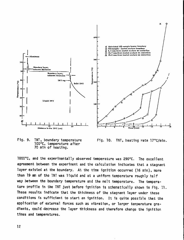
plate-explosive interface was increased at the rate of 17°C/min.
A graph of the experimental and calculation results for this experiment
is presented in Fig. 10. The time-dependent boundary temperature imposed on
the calculation was the experimentally obtained temperature at the explosive-
aluminum interface through the first 10 min of heating followed by a constant
17°C/min increase beyond 10 min. Thus, the calculation was forced to agree
with the experiment at this interface, and any temperature increases in TEPLO
greater than 17°C/min at times longer than 10 min would represent a contribu-
‘E’RT. After a heating period of 16 rein,tion from the energy source term QZ e
the calculated temperature in the first explosive cell at the explosive-
aluminum interface (using the kinetics listed in Table I) was greater than
11
II—A311mfnum
100 L I
I
Bonadary 2ayer,unknown tfdcknecc
90 .Boundary layer,
$
Uduiowmtldche,s — —
80c I TNTmp —
So3id TNTL
j 70
I
I
i!f-’60
I
I Liquid TNT
d-
1I40
I/’%
I I I I I I I I I I I I I0 I 1.
10 20~otanee in the TNT (cm)
Fig. 9. TNT, boundary temperature100”C, temperature after70 min of heating.
x
1’
)( Calc.MedHE -.-pleheaterb*duyO HE-s-pla -beated surfa.. b.udaryQ 6.3mnfr.m Le.t.d...c.t . . . . ..t.r1h*❑ 12.7 mm frozn heated surface o. ccntcrlin.A 19.0 mm from heated surface on cuiterllm
/
Fig. 10. TNT, heating rate 17°C/min.
1000”C, and the experimentally observed temperature was 290”C. The excellent
agreement between the experiment and the calculation indicates that a stagnant
layer existed at the boundary. At the time ignition occurred (16 rein),more
than 19 m of the TNT was 1iquid and at a uniform temperature roughly half
way between the boundary temperature and the melt temperature. The tempera-
ture profile in the TNT just before ignition is schematically shown in Fig. 11.
These results indicate that the thickness of the stagnant layer under these
conditions is sufficient to start an ignition. It is quite possible that the
application of external forces such as vibration, or larger temperature gra-
dients, could decrease the layer thickness and therefore change the ignition
times and temperatures.
12

o.
m
t-I.noo
●.0s
0U
$tom
Coo.
.-Nmm
.-4
N‘Va(n
..-4000--v
xxxx
xx
xx
r-l%mm
z.N
10
m“●
o0mo0Ln
0000mm
o0mo0m
1-mI0
1-*I0
xx
Hx
xto
Ci+
++
xi0
0InII
II1I
0mNII
II
atm.nv
fov
73
wu
.
-xoOc
m
1-i=
%mn
73

2. Composition B. To determine the heat-transfer mechanism in molten
Comp. B, a preliminary heating test was conducted in which the temperature at
the explosive-heater plate interface was increased at the rate of 10”C/min to
100”C and then maintained at 100”C. The experimental and calculational results
obtained are shown in Fig. 12. The excellent match between experiment and
calculation indicates that the heat-transfer mechanism is primarily conductive
and that the heat-transfer coefficients we used are relatively accurate. The
major difference in physical properties between TNT and Comp. B at tempera-
tures above the melting point of TNT is the viscosity. At 85”C, the viscosity
of TNT is approximately 0.1 to 0.12 P, and the viscosity of the Comp. B slurry
is 5 to 10 P. Because the thermal diffusivities of the two explosives are
approximately the same, the difference in heat-flow mechanisms can most likely
be attributed to the viscosity.
Following this experiment, three experiments were performed with Comp. B
at heating rates of 13, 17, and 23°C/min, respectively. Results obtained in
300
E
I
I ;
t
100 /---—---”/
Boundaylayer,
i \
unknmvathickness - i--— Alumhun
I Liquid TNT \l Solid TNT
I
I1
I~
Distanceinthe TNT(cm)
Fig. 11. TNT, heating rate -17°C/min,temperature profile after15 min of heating.
I I I I I I10
I I20 30
I40 50 60 70 (10Time (rein]
Fig. 12. HE heating, Comp. B, boundarytemperature 100”C, heatingrate 10°C/min.
14

these experiments are shown in Figs. 13-15. At the lowest heating rate
(13°C/min), the kinetic of Rogers7 and Robertson8 predict a S1ightly higher
ignition temperature than the experiment. The parameters used in the calcula-
tions are listed in Table I.
At a heating rate of 23°C/min, we obtained a better computational match
to the experinmt with RDX kinetics provided by Rogers. This result implies
that the decomposition rate of RDX is increased as it dissolved in TNT and
contradicts the observations made by Robertson8 that the decomposition rate
of RDX decreases when it is dissolved in TNT. Robertson’s explanationfor
the decrease in decomposition rate of RDX in solution was based on a short
chain-reaction decomposition mechanism. Thus, as the explosive molecules
I:,$
*eriment
0 Heater Merface❑ li[
Soo — O 6.33mmdeqi ITEP~
I
I //Cdr.datiom I 1,E“ z
O 43.1 2.44x10XoI II
3 0 43.1 2.OX1O37 I IIL )(47.5 3.16xlti’, ,&
j 200 _
1 /
j C/.
,/d
do/
100—
:/0”:>0”
Ml,’’’’” l-l++4
~ 8 10 12 14Time (mia)
ng rateFig. 13. Comp. B, heat13°C/mino
400 -
300 -
zoo -
100 —
Y’
o EkperImentd.HEsample heatez bound.zy
n oCalculated withJ&z
a 43.1 Zxld’41.5 3.16xl@*
$ 43.1 2.438x I@”
/
o
r~4-18
Time (mIn)
Fig. 14. Comp. B, heating rate17°C/min, HE sample-heater boundary.
15

kerlment
Heater boundary~ 6.35 mmdeep
CakumiomAZ
o 43.1 2.44X1+*n 43.1 ?..OX lr+7X 47.5 1.16x lP-
?
C/dC//
were separated by inert solvent, the
chain development was increasingly
inhibited. In a series of experiments
that were performed isothermally, over
the temperature range of 200 to 280°C,
Robertson found that TNT behaved as
an inert solvent.
A possible mechanism for the
apparent increase in RDX reaction rate
has been suggested by Rogers.g He
suggested the possibility of a series
of chain-type reaction between the
TNT and RDX producing intermediate
f’” >/0”P products that could either decompose
I @I I I I I I I I I 1 I I I
2 4 6 8 10 12 14
Time (m3n)
Fig. 15. Comp. B, heating rate23°C/min.
exothermally or catalyze the direct
decomposition of RDX. At 1ow heating
rates or at prolonged exposure to
lower temperatures, there would be
some time available for the reaction
of RDX with TNT and for intermediate
products to either decompose or cata-
1yze the decomposition of RDX. The mechanism suggested by Rogers has never been
experimentally verified.
3. Plastic-Bonded HMX (PBX 9501*). Results obtained in a heating exper-
iment with PBX 9501 are presented in Fig. 16. An excellent match between the
experiment and the TEPLO calculation, using the parameterslisted in Table I,
was obtained for the temperature as a function of time and space along the
center line of the explosive sample 6.35, 12.70, and 19.0 rnnfrom the sample-
heater interface. This verifies that the thermal diffusivity for PBX 9501
used in TEPLO is correct. The experimental time and temperature-to-ignition
is slightly higher and longer than time and temperature computed with TEPLO
using the HMX kinetics of Rogers.7 A slightly better match is obtained if
*95 wt% HMXS 2.5 wt% Estane, 2.5 wt% nitroplasticizer

1 t I I I I I I I I I I I I I 1 J2 4 6 8 10 12 14 16
‘rime (mi.)
Fig. 16. PBX 9501, heating rate22°C/min.
, 5. P1astic-Bonded DATB. A single,
the activation energy Is reduced from
52.Oto 51.3 kcal/mol. With either
set of kinetics, the agreement between
the experiment and the calculation is
very good from a practical standpoint.
4. P1astic-Bonded TATB (PBX-
!M!?lL The experimental and Calcu~a-tional results obtained with PBX 9502
are shown in Fig. 17. The agreement
is excellent between the experiment
and the time and temperature-to-
ignition using the values in Table I.
Our value for the thermal diffusivity
seems to be slightly in error because
the experinwntally obs~rved “nonreac-
tive” heat transfer is greater than
the calculated value. An extraordi-
nary feature of this experiment is
that the thermocouple leads 6.35 mm
from the heated surface survived
long enough to obtain an estimate
of the burning rate. The stlck-
burning rate is approximately 3mm/min.
unconfined, one-dimensional, heating
experiment was run with a Viton A-bonded DATB sample consisting of 5 wt%
Viton A and 95wt% DATB. In this experiment, the temperature at the sample
holder base plate was increased at the rate of 20°C/min. The experimental
and computational wsults are shown in Fig. 18. The DATB parameters used in
the calculations are listed in Table I. In the experiment, runaway reaction
started approximately 10° lower and 1 min sooner than the calculation predicts.
We were not able to calculate the experimentally observed temperature as
a function of time and space along the center line of the nonreacting region
*95 wt% TATB, 5 wt% Kel-F 800

JiAEqxrhent
O Heater bounduyO 6.35 nun deq
/
/
TEPLOCakulatlon
os z——
~ 59.88 3.5x l@”
o /
/
/
o ./O”’
//
#
/
/>// o0
0/
Fig. 17. PBX 9502,20°C/min.
of the charge. The
heating rate
1TEPI.O Calculationz
400X* 1.17X I&r Ir erlmentO Heste.r boundary~ 6.35 mmdeep Iv 12.70 mm deep , ,
I6
1/ /
1//
7’0
/
v
/0100 x/
“5 ./”
t ~
Time (mIn)
Fig. 18. 95 wt% DATB,heating rate
calculated temperature is, on the average, a
5 wt% Viton A,-.20”C/min.
few degrees
higher than the experimentally observed temperature. This difference indi-
cates that we have a small error in either the thermal conductivity or the
heat capacity. Since the error is very small, we did not attempt to redeter-
mine these parameters.
6. Plastic-Bonded NQ. Two, unconfined, one-dimensional, heating exper-
iments were run with Estane-bonded NQ samples consisting of 95 wt% NQ and
5 wt% Estane. The first run was performed at a heating rate of about 20°C/min
and the second at 10°C/min. The experimental results obtained in both runs
were unexpected. At the conclusion of both NQ runs, the glass foam used to
insulate the assembly was almost intact, and, in the space previously occupied
by the plastic-bonded NQ, we found a residue that appeared to be a low-density
18


carbon foam with almost the same dimensions as the starting materials. Fig-
ure 19 is a photograph of the residue. The aluminum plate used to hold the
sample was deformed and partially melted. In all previous experiments with
RDX-, HMX-, TATB-, and DATB-based explosives, all the explosive material was
consumed and the temperatures were high enough to melt and deform the foamed
glass insulation.
The experimental and computational results for the runs conducted at
heating rates of 10 and 20°C/min are presented in Figs. 20 and 21, and the
thermokinetic constants used in the calculations are given in Table I. In
neither run did we observe the temperature excursion predicted by the cal-
culation.
The residue was sampled and analyzed for carbon, hydrogen, and nitro-
gen. Results of this analysis are listed in Table II and compared with those
for NQ. From these data, normalized to C, we can derive an empirical formula
for the residue as CH1.13Nl.2600m07. Ifwe assume that this composition is
representative of the residue, then it represents the NQ (CH4N402) partially
burned to produce 1 nmle of water and some nitrogen or oxide of nitrogen, or,
in other words, an incomplete pyrolysis has taken place. The net energy change
in going fromNQ to NQ less 1 mole of water should be small, and this could
account for the absence of a temperature excursion. The exclusion of air and
its potential contribution to the oxidation reaction could be explained by
the fact that the foamed glass surrounding the assembly was well sealed and
was not disturbed during the pyrolysis.
TABLE II
RESIDUE ANALYSIS
Material
Residue from burn
NQb
aBy difference
bTheoretical
20
Elemental Analysis(Wt%)
c H N o
37.9 3.4 55.2 3.5a
11.5 3.9 53.8 30.8

~
/“/
//0-0
300
I
I /0 ~/
?~/0
I /
o
IG.
; 200 -
ij/0
/0
/:/ /0
i - 0,””0-
; .-‘/
./
T EPLO ctiCtitiOliE z
X=❑/
3.84X 10⁷
lfJo - 0/Dmerhnaat
O Heatar boandary0 6.35 mm da.p
4I I I 1 I II1 I I I16 18 20 22
!Zi
I I 1 1 1 I I I26 28
1 I30 32 34 36
Time (mha]
Fig. 20. 95 wt% NQ, 5 wt% Estane, heating rate 10°C/min.
/
/o
/
o io
/0 I
1O’x
/ /’100
0
4“ 7 v0,0”
/o’
/
/v
,v#’v’v , zTEP2.O Calculation
xWV x m z.84xlo9-
/v- Bcpeciment
0 Hes:erbotuuhryo 6. 3S mm deepV 12.70 mm deep
J 1 1 I I I I I 18 10 1?. 14 16 18 20 2f
Time (An)
Fig. 21. 95 wt% NQ, 5 wt% Estane, heating rate -20°C/min.
21

A series of thermal stability tests was run to obtain more information
on the thermal stability of NQ. Results obtained in the modified Henkin test
for low- and high-bulk-density NQ are presented in Fig. 22. These data indi-
cate that the critical temperature of high-bulk-density NQ is slightly lower
than that of the low-bulk-densitymaterial. Furthermore, a significant obser-
vation was made while conducting these experiments: No explosions or violent
reactions were obtained. The decomposition reaction was a mild gas evolution
that eventually ruptured the gas seal, without explosive force.
Thermogravimetric analysis (TGA) was performed with NQ and a few other
explosives of military interest. Results of this analysis are presented in
Fig. 23. These data indicate that a decomposition reaction starts at tempera-
tures between 180 and 190°C for NQ and that approximately 18% of the NQ remains
as a residue.
IV. TRANSIENTREACTIVEHEAT FLOW IN CONDUCTIVE AND CONVECTIVE SYSTEMS
A finite difference program has been developed to calculate the tempera-
ture fields and times-to-initiation for explosive materials. This program,
called EXPLO, was derived from TEPL0.6 A detailed description of the capa-
bilities of EXPLO with a few sample problems and a users’ guide have been
published by D. L. Jaeger. 10 It was designed to correct some of the minor
deficiencies in TEPLO and to expand the range of heat-transfer modes.
The major differences between TEPLO and EXPLO are the following:
1. The energy-source term in EXPLO is designed to handle first-order
kinetics with not more than five such energy-generating materials.
2. EXPLO has a routine to handle either free or forced convection.
Inclusion of first-order kinetics with multfple-source terms provides
the capability of determining, wi~h mixed explosives, the depletion rate of
each explosive component or the rate-determining explosive. This feature is
useful under conditions of slow heating or exposure to temperatures near the
critical temperature. Under these conditions, it is possible to deplete
small quantities of the more reactive materials or to have these materials
dominate in the initiation mchanism.
The convection routine makes it possible to compute the temperature as
a function of space and time in materials that undergo a solid-liquid phase
22

-.3
~
g:: 102
a
;
~ol _
1000IT (K)1.7 1:8 1.9 2.0 2:1 2,2
315.2 282.5 255.3 227.o 203.2 181.5
/
o
08c1
/x
O W Per X22.-N-494A
❑ 13igh-hulk density NQ,w.c.x reay.zallfzed
x E2gh-3u2k density NQ.DN? reeryst.llized
mmparacure (“C)
Fig. 22. Time to explosion.
0~ -$0 ‘~.20
20
b l“30
~ 40 0 TA2’3
\\
\
~l\
o
i 50 — o PAX:
3~ 60 A cow B
)
~\
oa
70 Onm
80 0 NQ!!
i ————0———. 0
90 6
I
----
100 I I100 200 300 400
Temperature (“C)
-o
Fig. 23. TGA, heating rate 10°C/min.
23

transition. With EXPLO, Jaeger computed the temperature profile in the TNT
system as a function of time and space. The EXPLO results were in excellent
agreement with the experiment.
v. CONCLUSIONS
The experimental and computational results obtained for
tested are summarized in Table III. These data indicate that
mal theory of initiation can be used, in almost all cases, to
the explosives
the simple ther-
predict the time
and temperature-to-ignition. Over the region of heating rates tested, the
kinetic source term can be approximated with a zero-order reaction as predicted
by Zinn and Rogers.4
With the exception of the plastic-bonded NQ formulations, the agreement
between the experiment and the calculation, using the kinetics listed in Table I,
is within 5%. The fact that we were able to predict the time and temperature- s
to-ignition with the TNT system is the existence of a stagnant layer of TNT at
the hot boundary. It is quite possible that under a set of boundary conditions
that would tend to significantly decrease the thickness of the layer, the time-
to-ignition would change.
The results obtained with NQ were not predictable with existing kinetics.
This indicates that at least one of the terms used to express the energy gener-
ation is in error. The most likely term is the heat of reaction, Q.
Y
24

ul-lHId-1
s1-
ENoEIn
●
In
In
w“m
I

REFERENCES
1.
2.
3.
4.
5.
6.
7.
8.
9.
10.
H. Hendin and R. McGill, “Rates of Explosive Decomposition of Explosives,”I&E Chem. ~, 6, p. 1391 (1952).
J. Zinn and C. L. Mader, “Thermal Ignition of Explosives,” J. Appl.Phys. 31, 2, p. 323 (1960).—
J. Wenograd, “The Behavior of Explosives at Very High Temperatures,”Trans. of the Farady Society~, p. 1612 (1961).
J. Zinn and R. N. Rogers, “Thermal Initiation of Explosives,” J. Phys.Chem. ~, p. 2646 (1962).
E. Catalano, D. Ornellas, E. Wrenn, E. Lee, J. Walton, and R. McGuire,“The Thermal Decomposition and Reaction of Confined Explosives,” SixthSymposium on Detonation, NWC (1976).
C. A. Anderson, “TEPLO: A Heat Conduction Code for Studying ThermalExplosions in Laminar Composites,” Los Alamos Scientific Laboratoryreport LA-4511 (November 1970).
R. N. Rogers, “Thermochemistry of Explosives,” Thermochemical Acts Q,pp. 131-139 (1975).
A. J. B. Robertson, “Thermal Decomposition of Explosives, Part II,”Trans. of the Farady Society~, p. 85 (1948).
R. N. Rogers, Los Alamos Scientific Laboratory, personal communication,June 1976.
D. L. Jaeger, “EXPLO: Explosives Thermal Analysis Computer Code,”Los Alamos Scientific Laboratory report LA-6949-MS (January 1978).
APPENDIX
REACTIVEHEAT-TRANSFERCALCULATIONSWITHMODIFIEDTEPLO
The TEPLO code was modifed to allow the use of a series of time-dependent
thermal boundary conditions and to study the transient heat conduction and
exothermic decomposition in a variety of high explosives subjected to time-
dependent boundary temperatures. The changes in the code allow it to be used
with the original fixed boundary conditions or with up to 10, linear, time-
dependent flux or temperature boundaries.
26

To use the code with the time-dependent thermal boundary conditions,
only a slight change was made to the boundary condition card, and immediately
following it, a card was added to the deck for each different boundary condition.
The remainder of the input cards are as described in LA-4511.
The modifed input is as follows:
Boundary Condition Card = Format (4E8”3, 14)
Columns
1-8 Inner boundary temperature in Kat initial time
9-16 Outer boundary temperature in K at initial time
17-24 Inner boundary flux in cal/cm2-s at initial time
25-32 Outer boundary flux in cal/cm2-s at initial time
33-36 Number of additional boundary conditions
Additional Boundary Condition Cards = Format (4E8*3)
Columns
1-8 Time (s) at end of inner boundary condition
9-16 Time (s) at end of outer boundary condition
17-24 Flux (cal/cm2-s) or temperature (K) at end of inner boundary
condition
25-32 Flux (cal/cm2-s) or temperature (K) at end of boundary condition
If columns 33-36 in the boundary condition card are left blank or coded
zero, the code will use the constant boundary conditions given for the initial
time (t = O). The number of additional boundary condition cards must equal
the value given in these columns. The code implements each of the time-
dependent, thermal boundary conditions by interpolating a linear heat or tem-
perature input curve, with the times and conditions from the previous card as
the first point on the curve and the times and conditions given on that card
as the last point.
When the time given on one boundary condition card has been reached or
exceeded, the heating curve defined by the next card is used. If a new bound-
ary condition is not defined for either the inner or outer boundary, the
code will use the previous boundary value specified until a new temperature
or flux is defined or for the duration of the run. Because the inner and
outer boundary conditions are independent of each other, a number of options
27

are available: (1) a flux input may be used at one boundary and a variable
temperature definition on the other; (2) one boundary condition can be varied
while holding the other constant; or (3) both boundary conditions can be var-
ied at the same time.
Figures 1-A and 2-A show the maximum temperature-time plots of the first
and last layers, respectively, of a four-layer cross section using the five
boundary condition cards listed below.
Card Column NumbersNo. 1 1 _-8 9-16 7-24 25-32 33-36
500. 400. 4.; 20. 40. 600. 700.
800. 900.: 1::: 2;;: 400. 1000.5 300. 300.
Layers 1 and 4 represent thin metal sheets with high thermal conductiv-
ities placed outside thick layers of insulating material with extremely low
conductivities. Thus, Figs. 1-A and 2-A closely represent the changes to the
boundary conditions as implemented by the code. Note that tim is plotted on
a log scale so that the curves are not composed of a series of straight lines
as they would be if a linear time scale were used.
28

UAX TEMPERATuRE vERSUS TIME IN LAYER 1.5,
?ss
?s,
ISs, 1
i-??.~!*33.1t5,s
I.,, +
I
TINE IN s
Fig. l-A. Temperature at the innerboundary.
MAX TENPESATURE vERSUS TINE IN UYER 4
r
4,s,9+ m-” :9-’ ,9-? ~,-t ,, II ,= , ,; z ,= >
TINZ IN s
Fig. 2-A. Temperature at the outerboundary.
29

SPECIAL DISTRIBUTION
HQ USAF/RDQRMWashington, DC 20330
HQ USAF/XOXFCMWashington, DC 20330
HQ USAF/SAMIBoiling AFBWashington, DC 20332
AFSC/IGFGAndrews AFBWashington, DC 20331
z Directorate of Strike ArmamentHQ AFSC/SDZAAndrews AFBWashington, DC 20334
HQ AFSC/DICAWAndrews AFBWashington, DC 20331
AFML/DO/AMICWright-Patterson AFB, OH 45433
AFIT/LDBuilding 640 Area BWright-Patterson AFB, OH 45433
ASD/ENFLAAttn: W. HartleyWright-Patterson AFB, OH 45433
AFFDL/FESAttn: C. D. CruzeWright-Patterson AFB, OH 45433
ASD/ENESHAttn: S. JohnsWright-Patterson AFB, OH 45433
ASD/XRPWright-Patterson AFB, OH 45433
TAC/DRARLangley AFB, VA 23665
30
No. of No. of!!@!?& @F!@
1
1
1
1
1
1
1
1
1
1
1
1
1
HQ TAC/INATLangley AFB, VA 23665 1
HQ SAC/LGWCOffutt AFB, NE 68113 1
HQ SAC/NRI (Stinfo Library)Offutt AFB, NE 68113 1
Central IntelligenceAgencyCRL/ADD/PublicationsWashington, DC 20505 1
AFWL/LRKirtland AFB, NM 87117 1
AFWL/SULTechnical LibraryKirtland AFB, NM 87117 1
AUL/LSE 71-209Maxwell AFB, AL 36112 1
Redstone Scientific Information Ctr.DRDMI-TBDUS Army Missile R&D CommandRedstone Arsenal, AL 35809
CommanderUS Army Armament R&D CommandAttn: DRDAR-TSS 59Dover, NJ 07801
Naval Surface Weapons CenterAttn: Code G-14Dahlgren, VA 22448
Naval Surface Weapons CenterWhite Oak LibraryWhite Oak, Silver Spring, MD 20910
NSWC/White Oak LaboratoryAttn: J. F. LeahyR-12, Building 613Silver Spring, MD 20910
1
1
1
2
1

Commanding OfficerNaval Weapons StationCode 2034Yorktown, VA 23691
No. of No. of@?@. !!!!?@
AFATL/DLDEEglin AFB, FL 32542 10
2 AFATL/DLEglin AFB, FL 32542 1
Commander (Code 233)Information Science DivisionNaval Weapons CenterChina Lake, CA 93555
Lawrence Livermore LaboratoryAttn: Dr. R. McGuire/L-324P.OL BOX 808Livermore, CA 94550
AFIS/INTIWashington, DC 20330 1
1HQUSAFE/DOQAPO New York 09012 1
HQ PACAF/DOOFQ1 Hickam AFB, HI 96853 2
Lawrence Livermore LaboratoryAttn: Dr. M. FingerP.O. Box 808Livermore, CA 94550
Accessions Division (DDC-TC)Defense Documentation CenterBuilding 5Cameron StationAlexandria, VA 22314
I 00-ALC/MMWMHill AFB, UT 84406
IPAC (Library)BOX 38Camp H. M. Smith, HI 96861 2
1DirectorUSATradoc Sys. Anal. ActivityAttn: ATAA-SL (Technical Library)White Sands Missile Range, NM 88002 1
1 Commanding OfficerNaval Weapons Support CenterAttn: Code 3031
2 Crane, IN 47522 3
AFATL/DLODLEglin AFB, FL 32542 2
37
*U.S. Government Ptinting Office: 1979–677-013129