copperlink ethernet extenders model 2158 & 2168 user manual file4 1.0 warranty information...
TRANSCRIPT
Part# 07M2157R-UMRev. BRevised 10/15/08
An ISO-9001CertifiedCompany
This is a Class A device and is intended for use light industrial environment. It is not intended approved for use in an industrial or residentiaenvironment.
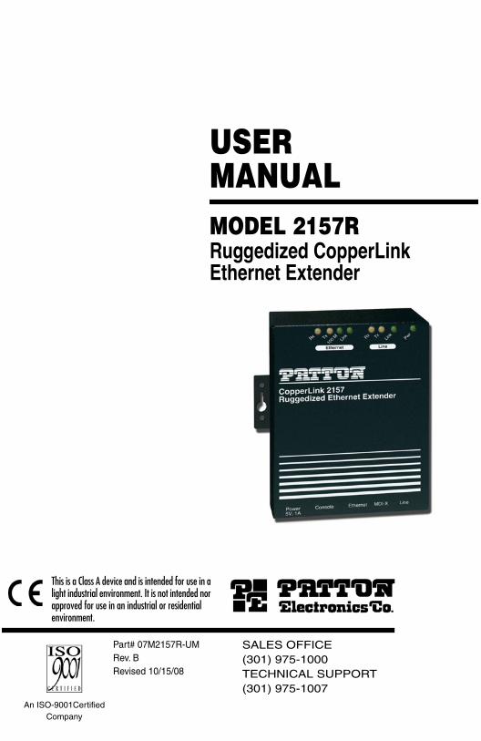
USER MANUALMODEL 2157RRuggedized CopperLink Ethernet Extender
SALES OFFICE(301) 975-1000TECHNICAL SUPPORT(301) 975-1007
in a nor l
CONTENTS
1.0 Warranty Information ................................................................. 31.1 Compliance................................................................................... 3
EMC Compliance:......................................................................... 3Safety Compliance: ...................................................................... 3PSTN Compliance: ....................................................................... 3
1.2 Radio and TV Interference (FCC Part 15) .................................... 31.3 CE Declaration of Conformity ....................................................... 41.4 Authorized European Representative........................................... 41.5 Service.......................................................................................... 41.6 Safety When Working With Electricity .......................................... 5
2.0 General Information.................................................................... 62.1 Features........................................................................................ 62.2 Description.................................................................................... 6
3.0 Installation................................................................................... 83.1 Connecting the Twisted-Pair Line Interface.................................. 93.2 Line Interface—Connecting the 10/100Base-T Ethernet Interface ..
10Connecting the 10/100Base-T Ethernet Port to a Hub or PC..... 10
3.3 Connecting Power ...................................................................... 113.4 Power Input Connector ............................................................... 11
External AC universal power supply........................................... 12External 48 VDC power supply................................................... 12
3.5 Console Port ............................................................................... 13
4.0 Operation................................................................................... 144.1 Front Panel LED Status Monitors ............................................... 14
ASpecifications ........................................................................... 15
A.1 General Characteristics .............................................................. 15A.2 WAN Characteristics ................................................................... 15A.3 Ethernet ....................................................................................... 15A.4 Extension distance and rate ....................................................... 16A.5 LED Indicators ............................................................................ 17A.6 Power and Power Supply Specifications .................................... 17A.7 Temperature Range .................................................................... 17A.8 Humidity ...................................................................................... 17A.9 Dimensions ................................................................................. 17
BModel 2157R Series Factory Replacement Parts and Accessories...................................... 18
CModel 2157R Series Interface Pin Assignment...................... 19
C.1 10/100Base-T Interface .............................................................. 19RJ-45 .......................................................................................... 19
2

C.2 CopperLink Interface .................................................................. 19RJ-11 .......................................................................................... 19
3

1.0 WARRANTY INFORMATION
Patton Electronics warrants all Model 2157R components to be free from defects, and will—at our option—repair or replace the product should it fail within one year from the first date of the shipment.
This warranty is limited to defects in workmanship or materials, and does not cover customer damage, abuse or unauthorized modification. If this product fails or does not performs as warranted, your sole recourse shall be repair or replacement as described above. Under no condition shall Patton Electronics be liable for any damages incurred by the use of this product. These damages include, but are not limited to, the following: lost profits, lost savings and incidental or consequential damages arising from the use of or inability to use this product. Patton Electronics spe-cifically disclaims all other warranties, expressed or implied, and the installation or use of this product shall be deemed an acceptance of these terms by the user.
Note Conformity documents of all Patton products can be viewed online at www.patton.com under the appropriate product page.
1.1 COMPLIANCE
EMC Compliance:
• FCC Part 15, Class A
• EN55022, Class A
• EN55024
Safety Compliance:
• IEC/EN 60950-1
• AS/NZS 60950-1
PSTN Compliance:
Note This device is not intended nor approved for connection to the PSTN.
1.2 RADIO AND TV INTERFERENCE (FCC PART 15)
This equipment generates and uses radio frequency energy, and if not installed and used properly—that is, in strict accordance with the manu-facturer's instructions—may cause interference to radio and television reception. This equipment has been tested and found to comply with the
4

limits for a Class A computing device in accordance with the specifica-tions in Subpart B of Part 15 of FCC rules, which are designed to provide reasonable protection from such interference in a commercial installa-tion. However, there is no guarantee that interference will not occur in a particular installation. If the equipment causes interference to radio or television reception, which can be determined by disconnecting the cables, try to correct the interference by one or more of the following measures: moving the computing equipment away from the receiver, re-orienting the receiving antenna, and/or plugging the receiving equipment into a different AC outlet (such that the computing equipment and receiver are on different branches).
1.3 CE DECLARATION OF CONFORMITY
We certify that the apparatus described above conforms to the require-ments of Council Directive 2004/108/EC on the approximation of the laws of the member states relating to electromagnetic compatibility; and Council Directive 2006/95/EC on the approximation of the laws of the member states relating to electrical equipment designed for use within certain voltage limits.
The safety advice in the documentation accompanying this product shall be obeyed. The conformity to the above directive is indicated by the CE sign on the device.
1.4 AUTHORIZED EUROPEAN REPRESENTATIVE
D R M Green
European Compliance Services Limited.
Avalon House, Marcham Road
Abingdon,
Oxon OX14 1UD, UK
1.5 SERVICE
All warranty and non-warranty repairs must be returned freight prepaid and insured to Patton Electronics. All returns must have a Return Materi-als Authorization number on the outside of the shipping container. This number may be obtained from Patton Electronics Technical Services at:
• Tel: +1 (301) 975-1007
• Email: [email protected]
• URL: http://www.patton.com
5

1.6 SAFETY WHEN WORKING WITH ELECTRICITY
• This device contains no user serviceable parts. The equipment shall be returned to Patton Electronics for repairs, or repaired by qualified service personnel.
• The external power adapter shall be a listed Limited Power Source. The mains outlet that is utilized to power the devise shall be within 10 feet (3 meters) of the device, shall be easily accessible, and protected by a circuit breaker.
• If an AC power adapter is used, ensure that the power cable used meets all applicable standards for the country in which it is to be installed, and that it is connected to a wall outlet which has earth ground.
• Hazardous network voltages are present in WAN ports regardless of whether power to the unit is ON or OFF. To avoid electric shock, use caution when near WAN ports. When detaching the cables, detach the end away from the device first.
• Do not work on the system or connect or disconnect cables during periods of lightning activity.
In accordance with the requirements of council direc-tive 2002/96/EC on Waste of Electrical and Electronic Equipment (WEEE), ensure that at end-of-life you sepa-rate this product from other waste and scrap and deliver to the WEEE collection system in your country for recy-cling.
This device is NOT intended nor approved for connec-tion to the PSTN. It is intended only for connection to customer premise equipment.
When the 2157R is mounted, it shall be secured in such a way as to withstand a vertical shear force of 50N or 14 pounds.
WARNING
WARNING
WARNING
6

2.0 GENERAL INFORMATION
Thank you purchasing this Patton Electronics product. This product has been thoroughly inspected and tested and is warranted for one year for parts and labor. If questions arise while installing or using this product, contact Technical Support at +1 (301) 975-1007.
2.1 FEATURES
• Easy-to-install Ethernet Extenders—no configuration required
• Auto-rate adaption ensures the highest rate possible for each exten-sion distance
• Data rates to 2.3 Mbps 4.6 Mbps
• Auto-sensing 10/100Base-T
• Extends network connections up to 30,000 ft (9,144 m) over 2-wire 24-AWG unconditioned lines (see Appendix A on page 16)
• Transparent operation to higher level protocols such as TCP/IP, DEC-net, NETBIOS, IPX, etc.
• Compatible with 802.1Q VLAN
• LED indicators for Power; Line Link, Line Transmit, Line Receive, Ethernet Link, Ethernet 100 M, Ethernet Transmit, Ethernet Receive
• Extended temperature ratings of -10 to 70C (2157R/E) and -40 to 85C (2157R/CC/E)
• Made in the USA
2.2 DESCRIPTION
The Patton Electronics Model 2157R Ruggedized CopperLink Ethernet Extender provides high-speed LAN connections between peered Ether-net LANs, remote PCs, or any other network enabled 10/100Base-T device.
Operating in pairs, one Model 2157R or 2157 can automatically forward LAN broadcasts, multicasts, and frames across a 2-wire voice-grade twisted-pair link. The data is passed transparently (unmodified) through the Ethernet Extenders. They automatically add and delete MAC addresses, only passing packets across the CopperLink line that are meant for the remote peered LAN.
7
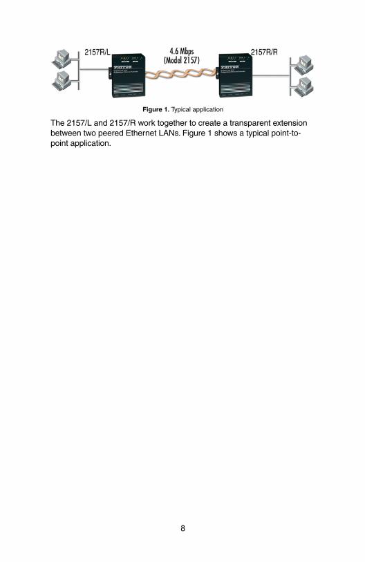
Figure 1. Typical application
The 2157/L and 2157/R work together to create a transparent extension between two peered Ethernet LANs. Figure 1 shows a typical point-to-point application.
8

3.0 INSTALLATION
Because the CopperLink Ethernet Extenders require no configuration, they can be installed quickly. Installation consists of the following:
• Connect the line interface between the units (refer to section 3.1, “Connecting the Twisted-Pair Line Interface” on page 10)
Note See Figure 2 for the rear-panel connectors locations.
• Connect the Ethernet interface (refer to section 3.2, “Line Interface—Connecting the 10/100Base-T Ethernet Interface” on page 11).
• Connect the power plug (refer to section 3.3, “Connecting Power” on page 12).
Figure 2. CopperLink Ethernet Extender rear panel
The Interconnecting cables shall be acceptable for external use and shall be rated for the proper applica-tion with respect to voltage, current, anticipated tem-perature, flammability, and mechanical serviceability.CAUTION
CopperLINK twisted-pair
RJ-45 interface
2157R
Powerjack
Ethernetport
Console
MDI-Xswitch
9

3.1 CONNECTING THE TWISTED-PAIR LINE INTERFACE
The Model 2157R supports communication between two peer Ethernet LAN sites over a distance greater than 30,000 ft (9,144 m) over 24 AWG (0.5 mm) twisted-pair wire.
Note The Model 2157R uses an auto-rate adaption feature to provide the fastest data rate possible over the wire and distance of each Ethernet extension. The actual distance and rate achieved for Ethernet extension may vary depending on the environment and type/gauge of the wire used.
Follow the steps below to connect the CopperLink interfaces.
Note The Model 2157R units work in pairs. One of the units must be configured as a (L) Local unit, and the other unit must be config-ured as a (R) Remote unit. It does not matter which end is the L and which is the R. The link is always initiated by the R unit. As long as the L unit is powered on, the R unit can establish a link by being powered on or by having its power reset.
1. To function properly, the two Ethernet Extenders must be connected together using twisted-pair, unconditioned, dry, metal wire, between 19 (0.9mm) and 26 AWG (0.4mm). Leased circuits that run through signal equalization equipment are not acceptable.
2. The Model 2157R is equipped with an RJ-11 interface. The Copper-Link interfaces are a two-wire interface. Observe the signal/pin rela-tionships on the CopperLink interface jack.
The RJ-11 connector on the CopperLink Ethernet Extender’s twisted pair interface is polarity insensitive and is wired for a two-wire interface. The signal/pin relationship is shown in Figure 3.
Figure 3. CopperLink Ethernet Extender (RJ-11) twisted pair line interface.
The Interconnecting cables shall be acceptable for external use and shall be rated for the proper applica-tion with respect to voltage, current, anticipated tem-perature, flammability, and mechanical serviceability.CAUTION
10
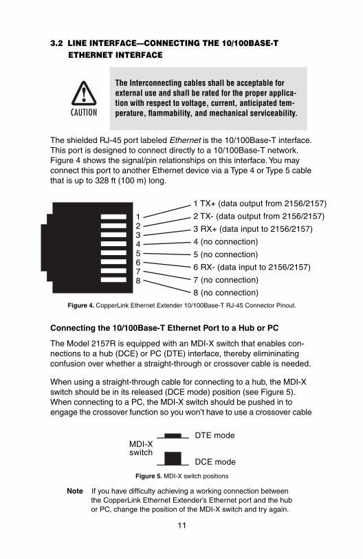
3.2 LINE INTERFACE—CONNECTING THE 10/100BASE-T ETHERNET INTERFACE
The shielded RJ-45 port labeled Ethernet is the 10/100Base-T interface. This port is designed to connect directly to a 10/100Base-T network. Figure 4 shows the signal/pin relationships on this interface. You may connect this port to another Ethernet device via a Type 4 or Type 5 cable that is up to 328 ft (100 m) long.
Figure 4. CopperLink Ethernet Extender 10/100Base-T RJ-45 Connector Pinout.
Connecting the 10/100Base-T Ethernet Port to a Hub or PC
The Model 2157R is equipped with an MDI-X switch that enables con-nections to a hub (DCE) or PC (DTE) interface, thereby elimininating confusion over whether a straight-through or crossover cable is needed.
When using a straight-through cable for connecting to a hub, the MDI-X switch should be in its released (DCE mode) position (see Figure 5). When connecting to a PC, the MDI-X switch should be pushed in to engage the crossover function so you won’t have to use a crossover cable
Figure 5. MDI-X switch positions
Note If you have difficulty achieving a working connection between the CopperLink Ethernet Extender’s Ethernet port and the hub or PC, change the position of the MDI-X switch and try again.
The Interconnecting cables shall be acceptable for external use and shall be rated for the proper applica-tion with respect to voltage, current, anticipated tem-perature, flammability, and mechanical serviceability.CAUTION
DCE mode
MDI-Xswitch
DTE mode
11

In its released position, the MDI-X switch enables straight-through con-nections (see Figure 6) or in its inserted position the MDI-X switch per-forms the crossover function (see Figure 7 on page 12).
Figure 6. Wiring diagram for connecting the CopperLink Ethernet Extender to a 10/100Base-T hub (MDI-X switch released)
Figure 7. MDI-X switch pressed in performs 10/100Base-T crossover function
3.3 CONNECTING POWER
The Model 2157R does not have a power switch, so it powers up as soon as it is plugged in.
An external AC or DC power supply is available separately. This connec-tion is made via the barrel jack on the rear panel of the Model 2157R. No configuration is necessary for the power supply (See Appendix B on page 19 for domestic and international power supply and cord options).
3.4 POWER INPUT CONNECTOR
The CopperLink Ethernet Extender comes with an AC or DC power supply.
• The supplies connection to the CopperLink Ethernet Extender is a 2.5 mm barrel receptacle with the center conductor positive (see Figure 6).
The Interconnecting cables shall be acceptable for external use and shall be rated for the proper applica-tion with respect to voltage, current, anticipated tem-perature, flammability, and mechanical serviceability.
2157 10/100Base-T PortRJ-45 Pin No.
10/100Base-T HubRJ-45 Pin No.
1 (TX+)--------------------------------------------------1 (RX+)
2 (TX-)---------------------------------------------------2 (RX-)
3 (RX+)--------------------------------------------------3 (TX+)
6 (RX-)---------------------------------------------------6 (TX-)
2157 10/100Base-T PortRJ-45 Pin No.
1 (TX+) 1 (TX+)
2 (TX-) 2 (TX-)
3 (RX+) 3 (RX+)
6 (RX-) 6 (RX-)
10/100Base-T DTERJ-45 Pin No.
CAUTION
12
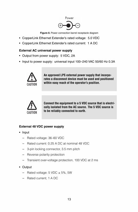
Figure 8. Power connection barrel receptacle diagram
• CopperLink Ethernet Extender’s rated voltage: 5.0 VDC
• CopperLink Ethernet Extender’s rated current: 1 A DC
External AC universal power supply
• Output from power supply: 5 VDC, 2A
• Input to power supply: universal input 100–240 VAC 50/60 Hz 0.3A
External 48 VDC power supply
• Input
– Rated voltage: 36–60 VDC
– Rated current: 0.25 A DC at nominal 48 VDC
– 3-pin locking connector, 3.5 mm pitch
– Reverse polarity protection
– Transient over-voltage protection, 100 VDC at 2 ms
• Output
– Rated voltage: 5 VDC ± 5%, 5W
– Rated current; 1 A DC
An approved LPS external power supply that incorpo-rates a disconnect device must be used and positioned within easy reach of the operator’s position.
Connect the equipment to a 5 VDC source that is electri-cally isolated from the AC source. The 5 VDC source is to be reliably connected to earth.
CAUTION
CAUTION
13
– 6-inch cable terminated with 2.5 mm barrel plug, center positive
3.5 CONSOLE PORT
The Console Port is only intended for use by Patton Electronics Technical Support technicians.
An approved LPS external power supply that incorpo-rates a disconnect device must be used and positioned within easy reach of the operator’s position.
Connect the equipment to a 36–60 VDC source that is electrically isolated from the AC source. The 36–60 VDC source is to be reliably connected to earth.
CAUTION
CAUTION
14

4.0 OPERATION
Once the CopperLink Ethernet Extenders are properly installed, they should operate transparently. No user settings required. This section describes reading the LED status monitors.
4.1 FRONT PANEL LED STATUS MONITORS
The Model 2157R features eight front-panel LEDs that monitor power, Ethernet signals, and the CopperLink connection. Figure 9 shows the front panel location of each LED. Table 1 describes the LED functions.
Figure 9. CopperLink Ethernet Extender standalone unit front panel
Table 1: Front panel LED description
LED Description
Power When lit, indicates the unit is powered on
Line Link • On solid—link is connected• Off—No signal detected
TX Flashing—Data is being transmitted from the local unit to the remote unit
RX Flashing—Data is being received at the local unit from the remote unit
Ethernet Link On—Ethernet is linked
100 M On—100 Mbps Ethernet is selected
TX Flashing—When data is transmitted from the unit to the LAN
RX Flashing—When data is received from the LAN
Link LEDPower LED
Link Tx LED
Link Rx LED
Ethernet Link LED
100 M LED
Ethernet Tx LED
Ethernet Rx LED
15

APPENDIX ASPECIFICATIONS
A.1 GENERAL CHARACTERISTICS
• Compact low cost plug-and-play router
• 10/100 Ethernet
• Unlimited host support
• Eight front panel LEDs indicate Power, WAN, Ethernet LAN speed and status
• Convenient and standard RJ connectors for Ethernet and line
• External UI or 48 VDC power supply options
• Standard 1-year warranty
A.2 WAN CHARACTERISTICS
• 4.6 Mbps speed
• RJ-11 connector
• Uses two-wire unconditioned twisted-pair
A.3 ETHERNET
• Full-duplex, auto-sensing,10Base-T/100Base-TX Ethernet
• Standard RJ-45 and built-in MDI-X crossover switch
• IEEE 8021.d transparent learning bridge up to 1,024 addresses and spanning tree
• Compatible with 802.1Q VLAN
• Addresses deleted after 5 minutes of inactivity
16

A.4 EXTENSION DISTANCE AND RATE
• 4.6 Mbps speed
• Distances up to 30,000 ft (9,144 m) on 24 AWG (0.4 mm) wire
• Auto-adjusting rate picks best rate for a given extension distance (see tables below)
A.5 LED INDICATORS
• Eight LED indicators
• Power
• Line Link, Transmit, and Receive
• Ethernet Link, 100M, Transmit, and Receive
A.6 POWER AND POWER SUPPLY SPECIFICATIONS
• Either AC or DC options are available
• Connection to the CopperLink Ethernet Extender requires +5VDC ±5% DC power (1.0A minimum). Center pin is +5V. The barrel type plug has a 2.5/5.5/10mm I.D./O.D./shaft length dimensions
• CopperLink Ethernet Extender’s rated voltage: 5.0 VDC
• CopperLink Ethernet Extender’s rated current: 1A DC
Table 2: Model 2157R Extension Distances
Line Rate
No Noise
26g (0.4 mm) 24g (0.5 mm) 22g (0.6 mm) 20g (0.8 mm) 19g (0.9 mm)
kbps miles km miles km miles km miles km miles km
200 4.4 7.0 5.7 9.4 8.0 13.1 10.3 16.8 12.1 19.7
392 4.0 6.6 5.4 8.8 7.5 12.3 9.7 15.8 10.8 17.5
520 3.8 6.2 5.1 8.3 7.1 11.6 9.2 14.9 9.7 15.8
776 3.5 5.6 4.6 7.5 6.0 9.8 7.8 12.7 8.8 14.3
1160 3.0 4.9 4.0 6.4 5.2 8.4 6.7 11.0 7.5 12.3
1544 2.8 4.6 3.7 6.1 4.9 7.9 6.4 10.3 6.7 11.0
2056 2.5 4.0 3.3 5.3 4.2 6.9 5.6 9.0 5.9 9.6
2312 2.3 3.8 3.1 5.0 4.0 6.6 5.3 8.6 5.6 9.1
2696 2.3 3.7 3.0 5.0 4.0 6.4 5.2 8.4 5.5 8.9
3080 2.2 3.6 3.0 4.8 3.9 6.3 5.0 8.2 5.4 8.7
3464 2.1 3.4 2.7 4.5 3.6 5.8 4.7 7.6 4.9 8.0
3848 1.9 3.1 2.5 4.1 3.3 5.3 4.3 7.0 4.5 7.4
4232 1.7 2.8 2.3 3.7 2.9 4.8 3.9 6.3 4.1 6.6
4616 1.5 2.5 2.0 3.3 2.6 4.2 3.4 5.5 3.6 5.9
17

A.7 TEMPERATURE RANGE
• -10 to 70°C (2157R/E)
• -40 to 85°C (2157R/CC/E)
A.8 HUMIDITY
Standard:Up to 90% non-condensing
Conformal Coated: 85% condensing humidity from -10 to 35°C
A.9 DIMENSIONS
1.5H x 4.13W x 3.75D in.(3.81H x 10.5W x 9.53D cm)
18

P
212121
21
21
2107Po08482412Po08080808080808080808
APPENDIX BMODEL 2157R SERIES FACTORY
REPLACEMENT PARTS AND ACCESSORIES
*Only required with optional UI power supply (08055DCUI)
atton Model # Description
57R Base Models57R/EUI Ruggedized 4.6 Mbps CopperLink Ethernet Extender57R/EUI-2PK Ruggedized 4.6Mbps CopperLink Ethernet Extender Kit:
includes one local (L) and one remote (R) Model 2157R57R/CC/E Extended Temperature 4.6 Mbps CopperLink Ethernet
Extender57R/CC/E-2PK Extended Temperature 4.6 Mbps CopperLink Ethernet
Extender Kit: includes one local (L) and one remote (R) Model 2157R
57R User ManualM2157R-UM User Manualwer Supplies055DCUI 100–240VAC (+5V reg. DC/2A) Universal Input Adapter.V-PSM3 DC/DC; 48V in 5V 1A outV-PSM DC/DC; 24V in 5V 1A outV-PSM DC/DC; 12V in 5V 1A outwer Cords*05US American Power Cord05EUR European Power Cord CEE 705UK United Kingdom Power Cord05AUS Australian Power Cord05DEN Denmark Power Cord05FR France/Belgium Power Cord05IN India Power Cord05IS Israel Power Cord05JAP Japan Power Cord05SW Switzerland Power Cord
19

APPENDIX CMODEL 2157R SERIES INTERFACE PIN ASSIGNMENT
C.1 10/100BASE-T INTERFACE
RJ-45
• Pin 1: TX+
• Pin 2: TX-
• Pin 3: RX+
• Pin 6: RX-
• Pins 4, 5, 7, 8: no connection
C.2 COPPERLINK INTERFACE
RJ-11
• Pin 2: RING
• Pin 3: TIP
• Pins 1 & 4: no connection
20

Notes
________________________________________________________
________________________________________________________
________________________________________________________
________________________________________________________
________________________________________________________
________________________________________________________
________________________________________________________
________________________________________________________
________________________________________________________
________________________________________________________
________________________________________________________
________________________________________________________
________________________________________________________
________________________________________________________
________________________________________________________
________________________________________________________
________________________________________________________
________________________________________________________
________________________________________________________
________________________________________________________
________________________________________________________
21

Notes
________________________________________________________
________________________________________________________
________________________________________________________
________________________________________________________
________________________________________________________
________________________________________________________
________________________________________________________
________________________________________________________
________________________________________________________
________________________________________________________
________________________________________________________
________________________________________________________
________________________________________________________
________________________________________________________
________________________________________________________
________________________________________________________
________________________________________________________
________________________________________________________
________________________________________________________
________________________________________________________
________________________________________________________
22

Notes
________________________________________________________
________________________________________________________
________________________________________________________
________________________________________________________
________________________________________________________
________________________________________________________
________________________________________________________
________________________________________________________
________________________________________________________
________________________________________________________
________________________________________________________
________________________________________________________
________________________________________________________
________________________________________________________
________________________________________________________
________________________________________________________
________________________________________________________
________________________________________________________
________________________________________________________
________________________________________________________
________________________________________________________
23

Notes
________________________________________________________
________________________________________________________
________________________________________________________
________________________________________________________
________________________________________________________
________________________________________________________
________________________________________________________
________________________________________________________
________________________________________________________
________________________________________________________
________________________________________________________
________________________________________________________
________________________________________________________
________________________________________________________
________________________________________________________
________________________________________________________
________________________________________________________
________________________________________________________
________________________________________________________
________________________________________________________
________________________________________________________
Copyright © 2008Patton Electronics Company
All Rights Reserved.
24