copper refinery modernisation, mopani copper mines plc ... refinery upgrade.pdf · refining cells,...
TRANSCRIPT

Copper Cobalt Africa, incorporating the 9th Southern African Base Metals Conference Livingstone, Zambia, 10–12 July 2018 Southern African Institute of Mining and Metallurgy 1
Copper Refinery Modernisation, Mopani Copper Mines Plc, Mufulira, Zambia
Maambo Chooye¹, Rakesh Patel¹, Addin Pranowo² and Brendan O’Rourke³*
¹Mopani Copper Mines, Mufulira, Zambia
²Glencore Technology, Townsville, Australia ³Glencore Technology, Brisbane, Australia
*Corresponding author: [email protected]
The electrolytic refining of copper has been conducted at Mufulira, Zambia, since 1939. The original refinery has been upgraded and expanded since then to match the output of anodes produced at the Mufulira, Luanshya, and Nkana smelters at various times; however, by the end of 2012, it was recognised that customer expectations regarding cathode physical quality and chemical purity have increased due to the introduction of new copper refining technologies. In June 2013, Mopani Copper Mines Plc (MCM) committed to the modernisation of the copper refinery that included the conversion of the existing refinery to the ISAPROCESS™ technology, installation of electrode handling equipment, upgraded electrolyte circulation systems, and upgraded process control systems. This paper describes the equipment, technologies and new operational practices that constitute the Mufulira Refinery Upgrade Project. All activities have been progressively completed since late 2014 and have culminated with the registration of a new London Metals Exchange cathode brand, MCM2, in July 2017. The MCM Refinery is the first copper electrorefining plant in Africa to utilise the ISAPROCESS™ technology.
INTRODUCTION Copper has been electrolytically refined in Mufulira, Zambia for over 75 years. The original refinery has been expanded several times and one part of the refinery was expanded to conduct commercial-scale electrowinning operations. These operations included in-situ leaching, vat leaching, and heap leaching of oxide ores. A dedicated solvent extraction plant was associated with each leach operation. The primary objective of the Refinery Modernisation Project was to ensure that current and future customer expectations could be fully satisfied, and to implement productivity improvements, whilst allowing the refinery to have the flexibility to source anodes with higher impurity levels than currently received. This necessitated a change in the refining technology used by Mopani Copper Mines Plc (MCM). MCM selected the ISAPROCESS™ technology due to its extensive record of converting starter-sheet refineries to permanent stainless steel cathode plates. At the same, MCM also took the opportunity to upgrade and modernise its electrode handling systems, electrolyte circulation systems and process control systems. Owing to the requirement for the existing refinery to maintain copper production operations at full capacity, the upgrade activities were conducted progressively over a four-year period. The constructions activities are described below in more detail. The operational improvements since completion of the project are also described in detail.

2
PROCESS SELECTION Layout Various combinations of cell house layout and design have been implemented in ISAPROCESS™ copper refineries. MCM was constrained in some cases due to the requirement to maintain full copper cathode production capacity during the modernisation activities. In particular, this meant that the new electrode handling machines had to be located in areas that were not being used for existing production activities. The location of anode receipt from the smelter was fixed by the existing transport infrastructure. Design Criteria The principal design objectives for the project were:
• Long-term production forecasts; • customer requirements; • productivity improvement; • upgrade of electrolyte circulation systems; • future expansion options.
Long-term production forecast MCM is upgrading the existing Mufulira Mine and expects to complete the new Synclinorium Mine and Concentrator Project in 2019. When combined with external concentrate feed treatment at the MCM smelter, this will enable the Mufulira Smelter to increase production to 225 000 tonnes per annum. The modernised refinery production capacity matches this requirement. Customer requirements MCM has been producing copper cathode marketed under the London Metal Exchange (LME) Registered Brand MCM. Cathode produced by the modernised refinery is now marketed under the LME Registered Brand MCM2. The cathode bundle being produced now has many advantages over the previous style. It is compact, easier to handle and transport and no longer has the protruding starter-sheet loops associated with starter-sheet cathode. Productivity improvement Using starter-sheet technology, MCM was operating four tank houses plus a starter-sheet production aisle with-in their refinery complex. Glencore Technologies experience with ISAPROCESS™ copper refinery conversions conducted over the past 30 years was that conversion to stainless steel cathode plate technology achieved direct productivity improvements of 25% to 30% when compared with starter-sheet technology. In the specific MCM case, this has allowed MCM to reduce the operational footprint to three tank houses, with an associated reduction in the number of operating overhead cranes, refining cells, and, importantly, copper inventory. Further productivity improvements have been made in the electrode handling task. The elimination of starter sheets has removed all aspects of starter-sheet production – starter-sheet production cells, manual stripping, sorting, and preparation activities, loop production, hanger bar assembly, manual cell loading, alignment activities and replacement of falling cathode due to broken loops. The introduction of the ISAPROCESS™ permanent stainless steel cathode system requires a dedicated cathode stripping machine (CSM) to perform cathode stripping operations. The CSMs selected at MCM are capable of fully automatic operation and eliminate all steps that were performed manually. At the same time, MCM elected to introduce a fully automated anode preparation machine (APM), anode scrap washing machine (ASWM), and upgraded its overhead refinery cranes to suit the new electrode handling machines. Upgrade of electrolyte circulation systems With the expected increases in copper production intensity, it was determined that the existing circulation systems required additional circulation capacity and improved process control. At the same
3
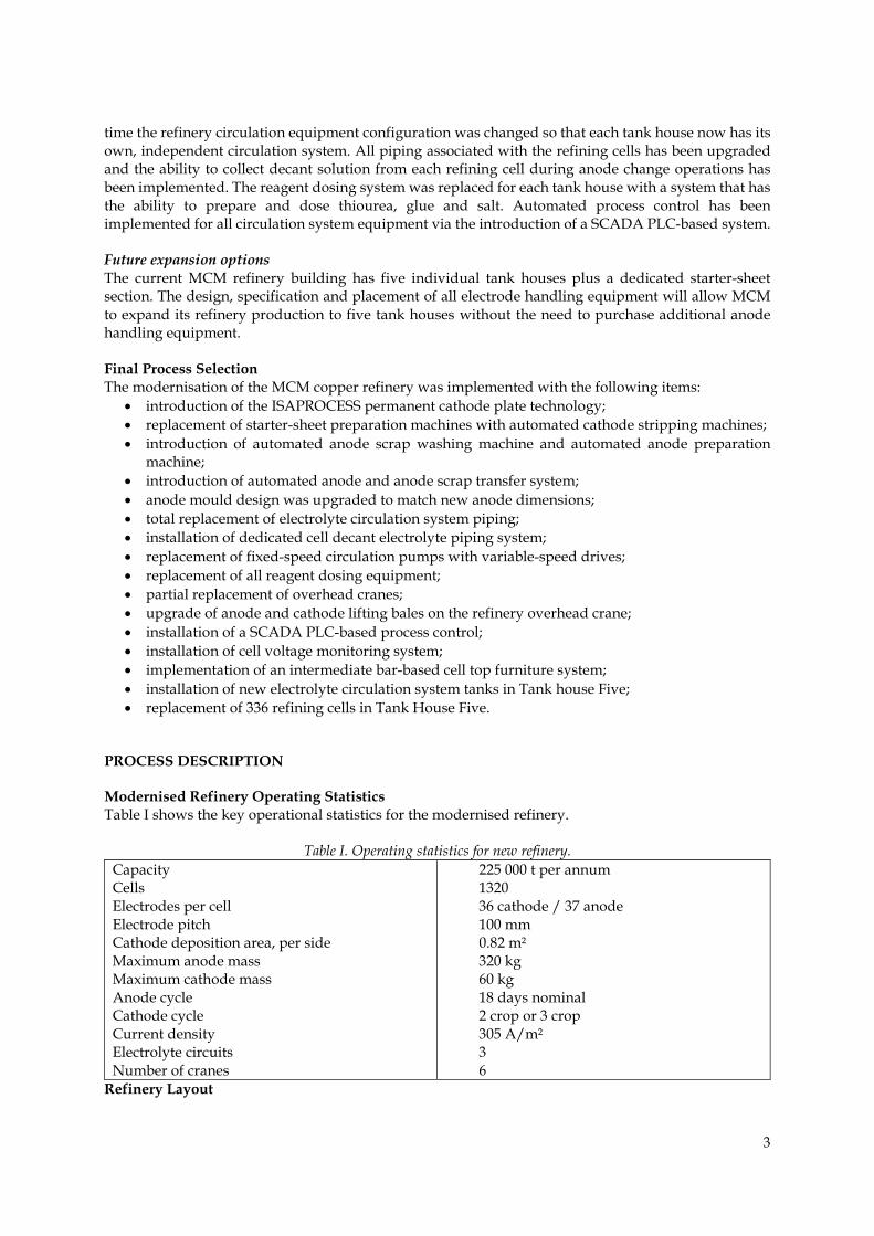
time the refinery circulation equipment configuration was changed so that each tank house now has its own, independent circulation system. All piping associated with the refining cells has been upgraded and the ability to collect decant solution from each refining cell during anode change operations has been implemented. The reagent dosing system was replaced for each tank house with a system that has the ability to prepare and dose thiourea, glue and salt. Automated process control has been implemented for all circulation system equipment via the introduction of a SCADA PLC-based system. Future expansion options The current MCM refinery building has five individual tank houses plus a dedicated starter-sheet section. The design, specification and placement of all electrode handling equipment will allow MCM to expand its refinery production to five tank houses without the need to purchase additional anode handling equipment. Final Process Selection The modernisation of the MCM copper refinery was implemented with the following items:
• introduction of the ISAPROCESS permanent cathode plate technology; • replacement of starter-sheet preparation machines with automated cathode stripping machines; • introduction of automated anode scrap washing machine and automated anode preparation
machine; • introduction of automated anode and anode scrap transfer system; • anode mould design was upgraded to match new anode dimensions; • total replacement of electrolyte circulation system piping; • installation of dedicated cell decant electrolyte piping system; • replacement of fixed-speed circulation pumps with variable-speed drives; • replacement of all reagent dosing equipment; • partial replacement of overhead cranes; • upgrade of anode and cathode lifting bales on the refinery overhead crane; • installation of a SCADA PLC-based process control; • installation of cell voltage monitoring system; • implementation of an intermediate bar-based cell top furniture system; • installation of new electrolyte circulation system tanks in Tank house Five; • replacement of 336 refining cells in Tank House Five.
PROCESS DESCRIPTION Modernised Refinery Operating Statistics Table I shows the key operational statistics for the modernised refinery.
Table I. Operating statistics for new refinery. Capacity Cells Electrodes per cell Electrode pitch Cathode deposition area, per side Maximum anode mass Maximum cathode mass Anode cycle Cathode cycle Current density Electrolyte circuits Number of cranes
225 000 t per annum 1320 36 cathode / 37 anode 100 mm 0.82 m² 320 kg 60 kg 18 days nominal 2 crop or 3 crop 305 A/m² 3 6
Refinery Layout

4
The existing MCM Refinery design is typical for the era in which it was built. Overhead refinery cranes from that era had very slow operating speeds hence the design objective was to minimise the length of crane runs. Crane rail heights were also set as low as possible to reduce lifting and lowering times for electrodes. This lead to refineries being built with multiple aisles, short crane runs with a low operating height over the electrolysis cells. Movement of material was best managed by having a common centrally located aisle running the length of the refinery building. Industrial standard forklifts were also not common at the time so rail was used as a method for moving anodes, anode scrap and copper cathodes. Owing to the existing layout, all of the new electrode handling machines can only be located in the central common aisle. This led to the situation where anodes and anode scrap need to be conveyed up to 120 m if only one APM and one ASWM unit are installed. By working with the supplier of the APM and ASWM, an innovative ground-running transfer car system for carrying anodes and anode scrap was specially developed for each machine. All of the electrode handling machines are designed to be serviced by forklifts.
Figure 1. New overhead crane with drip tray carrying cathode plates.
Electrode Handling Equipment Anode preparation machine Anodes are received from MCM’s copper smelter via rail and forklift. Anodes are loaded to the APM by forklift for weighing, blade pressing, lug-offset pressing and contact milling. Contact milling is used to ensure that anodes hang vertically in the cell and ensure best possible current distribution in the refining cells. The anodes are then transported in loads of 36 anodes to the appropriate tank house using the anode transfer car system. The APM was supplied by MESCO, Japan. Anode transfer cars A transfer car system is used to move anodes and anode scrap with-in the refinery building. Each transfer car runs at ground level and carries 36 pieces of anode or anode scrap to or from the respective APM or ASWM. Each transfer car services nine fixed set-down or pick-up positions located across the length of the refinery building. The Anode transfer car system was supplied by MESCO, Japan. Cathode stripping machines Three medium speed CSMs have been installed at MCM. One CSM is installed in each operating tank house; however, each CSM has the capacity to service the electrodes from the two bays in each tank house. The CSMs have been specially designed to interact with manually operated and low clearance overhead cranes. This means that conveyors are used to transfer cathode plates instead of fast-moving trolleys. This eliminates the possibility of a crane bale to trolley collision. A forklift is used to remove the finished cathode bundles to the product despatch area. The wash water used to remove electrolyte

5
from the cathode deposits is heated using electric heaters. The wash water system is designed for future conversion to steam heating. The CSMs were supplied by MESCO, Japan. Anode scrap washing machine Anode scrap is moved from the refining cells by overhead crane and then conveyed to the ASWM via the transfer car system. In the ASWM, the scrap is washed to remove any adherent slimes and then formed into bundles for forklift removal. Anode scrap is returned to the copper smelter. The ASWM was supplied by MESCO, Japan. Overhead crane upgrade The change in refinery electrodes, electrode pitch and cell-top furniture necessitated that new anode and cathode plate bales were required for the overhead cranes. At the same time, MCM decided to replace four of the six existing refinery cranes. MCM utilises crane transfer cars located at the end of each tank house. This allows the overhead cranes to be moved to another aisle when needed, thus reducing the overall number of cranes required in the refinery. The new cranes and lifting bales were designed and supplied by DEMAG, South Africa. Electrolyte Circulation Many parts of the existing circulation systems were not suitable for the increased operating intensity associated with the ISAPROCESS™ technology. A higher and more consistent cell electrolyte flowrate was the major change required. This meant that all electrolyte piping was upgraded, together with the associated circulation pumps. The use of variable-speed pumps was required so that a responsive flow control scheme could be implemented. The electrolyte is distributed to the cells by direct pumping without an intermediate head tank. Owing to the introduction of the thiourea reagent to replace Tembind, the existing reagent dosing systems were also replaced.
Figure 2. ISAPROCESS™ permanent stainless steel cathode plates in service.
Process Control and Monitoring To ensure the correct electrolyte conditions for electrolysis at the higher operating intensities, improved process control of the operation was required. This has been achieved by implementation of a SCADA-based PLC system for the electrolyte circulation. The Siemens PLC-7 system was used for the SCADA configuration.
6
Refinery Cells As most of the existing refining cells were retained, the dimensions of the new stainless steel cathode plates were matched to the internal cell dimensions. The dimensional design of the anode was changed to match the new cathode plate dimensions. Owing to the inherent straightness of the stainless steel cathodes, the electrode pitch in the cell was able to be reduced to 100 mm, which provides reduced power consumption when compared with the starter-sheet design. The cathode plates were designed and supplied by Glencore Technology, Australia. The upgrade of the electrolyte circulation system required changes to the electrolyte feedpipe for each cell. At the same time, an individual cell flow-control device was included in the new piping design. New cells were installed in Tank house Five to allow for full implementation of the decant collection system. It was necessary to change all cell-top furniture to an intermediate bar design. The end cell busbars on all sections required modification to suit the ISAPROCESS™ system. The additional busbar elements and intermediate bars were designed and supplied by Copalcor, South Africa. CONSTRUCTION In all cases, the scheduling of construction activities was dictated by cathode production requirements. With four tank houses still available for production, each of the three modernised tank ouses was consecutively taken off-line for refurbishment over a two-year period. At the same time, MCM was forced to curtail production during 2016 due to power supply restrictions in place in Zambia. The major construction milestones are listed below: Jan–May 2014 New end cell busbars designed and installed July–Dec 2014 Preparation of electrode handling machine areas Oct–Dec 2014 Installation of electrode handling machines – TH1 & TH4 CSM’s Feb–March 2015 Installation of electrode handling machines – APM, ATS May 2015 Installation of electrode handling machines - TH5 CSM June–Aug 2015 Replacement of reagent system, piping and pumps – TH4 May–Aug 2016 Installation of new overhead cranes Feb- July 2016 SCADA and cell voltage monitoring installed Mar–Dec 2016 New circulation system for TH5 installed May–Oct 2017 Installation of new cells – TH5 May–Nov 2017 Replacement of piping and pumps – TH 1 November 2017 Replacement of piping TH5
COMMISSIONING MCM formed a dedicated commissioning team to ensure that the transition between the two operating systems was performed safely and in step with the completion of construction/installation activities. A major emphasis was placed on training across all disciplines: metallurgy, operations and maintenance. At the same time, the operational requirements and testing to obtain LME registration for the new cathode were completed. The key commissioning milestones are listed below: Jan–Feb 2015 Operations and maintenance training program completed at CRL Australia
and PASAR, Philippines March 2015 Full commissioning of CSM TH4, APM, ATS, ASWM and TH4 circulation
systems

7
Apr–July 2015 Full conversion of TH4 for first LME registration testing program Jan–Dec 2016 Second LME registration testing period – TH4 June 2016 Full conversion of TH1 and commissioning of CSM TH1, CSM TH5 June–Nov 2016 Progressive commissioning of new refinery overhead cranes June 2017 LME registration granted for MCM2 brand October 2017 Central control room operational for SCADA and cell voltage monitoring
systems October 2017 Full conversion of TH5 and commissioning of TH5 circulation system October 2017 Starter-sheet oOperations ceased Commissioning engineers were supplied from MESCO, DEMAG and Glencore Technology for the electrode handling equipment. Specific ISAPROCESS™ training services and process engineers were also provided by Glencore Technology. MCM also retained the services of two expatriate electrode handling machine specialists to provide on-site training. PRODUCTION AND OPERATIONAL IMPROVEMENTS Table II details the improvements in several refinery production performance indicators since the conversion of the refinery to the ISAPROCESS™. The level of improvement achieved is consistent with the levels foreseen during the feasibility study phase of the project. Table II. Cathode purity improvement – ISAPROCESS vs conventional.
Impurity (ppm)
Conventional Full ISAPROCESS
Note
2014 average 2015 average 2016 average 2017/8 average S
Pb Ni As Bi Sb Se Ag Sn Te Zn Fe
3.74 1.50 1.19 1.24 0.43 0.36 1.07 6.48 0.28 0.45 0.56 <2
6.29 1.81 1.27 1.48 0.41 0.51 1.24 6.20 0.24 0.43 0.46 <2
4.93 1.42 0.70 1.27 0.26 0.54 0.84 5.35 0.31 0.46 0.48 0.48
4.43 0.53 0.58 0.50 0.20 0.47 0.28 5.95 0.25 0.31
0.418 0.35
Similar Improved Improved Improved Improved
Similar Improved
Similar Similar
Improved Similar Similar
Table I shows the long-term improvement in copper cathode impurity levels for the common cathode copper impurities. These levels easily comply with the requirements for LME Grade A copper cathode. At least four different mechanisms for cathode impurity exist in an industrial-scale copper electrorefinery. Each mechanism and the associated impurities are briefly described below with reference to Mopani’s specific anode impurities:
• inclusion of slimes in cathode deposit: indicators are lead, selenium, arsenic, bismuth, tellurium and antimony;
• occlusion of electrolyte in cathode deposit: indicators are nickel, iron and arsenic; • electrolytic codeposition: indicator is silver; • precipitation on cathode deposit surface: bismuth, antimony, tellurium and arsenic.
Impurities associated with slimes inclusion have shown the greatest improvement. The inherent straightness of the permanent stainless steel cathode plate means the probability of a slimes particle making contact with the cathode deposit during electrolysis is significantly lower than for a starter
8
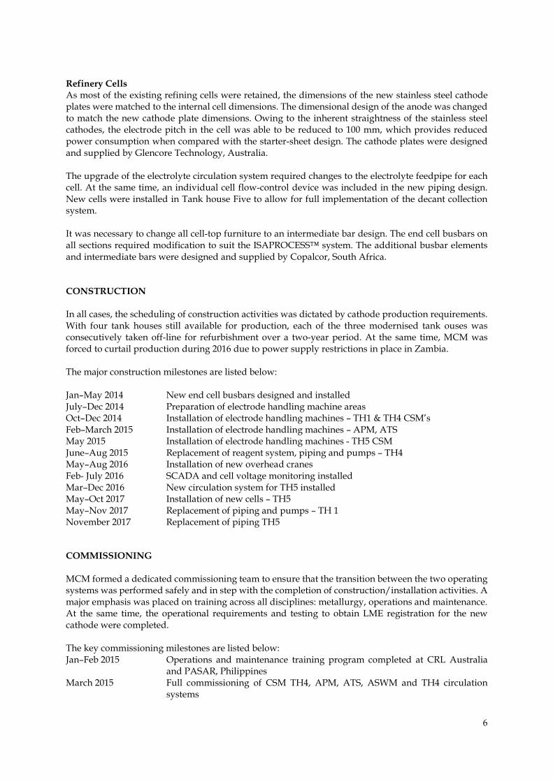
sheet. In addition, permanent stainless steel cathode plate technology allows for shorter crop ages, which reduces the probability of slimes inclusion occurring. The level of impurity associated with electrolyte occlusion has also improved noticeably. This is attributed to the improved cathode deposit smoothness achieved by MCM since introducing the thiourea reagent. MCM upgraded its electrolyte circulation system to ensure that all refining cells are now receiving the correct flowrate of electrolyte, and thus reagents are always available at the cathode deposit surface during electrolysis operations. The inherent flatness of a permanent stainless steel cathode plate and the shorter crop ages also contributes to the cathode deposit smoothness. No change in the silver assay at MCM indicates that the level of silver codeposition is not influenced by the conversion to permanent cathode plates. MCM does not have sufficient quantities of bismuth, antimony and tellurium in its anode and electrolyte for the surface precipitation impurity mechanism to be noticeable. Customer Acceptance Figure 3 shows the percentage of copper cathode production that was suitable for direct despatch to customers as LME Grade A cathode. The long-term trend for starter-sheet production was 86.6%, with significant variability in conformance. This indicator has improved to 97.7% since the conversion of the refinery to the ISAPROCESS™, with a vast reduction in variability.Figure 4 shows a photograph of typical cathodes.
Figure 3. Cathode product dispatchability.

9
Figure 4. Copper cathode at CSM and existing trolley system.
Current Efficiency Figure 5 shows the long-term trend for refinery current efficiency (CE). The long-term trend for CE was 85.9%. This indicator has improved to 97.5% since the conversion to the ISAPROCESS™, due to significant reduction in the number of short circuits. The variability in month-to-month performance has also reduced significantly.
Figure 5. Current efficiency improvement after conversion.
Productivity Figure 6 shows the long-term trend in labour productivity for the refinery. It is important to correlate this measure against the actual production level at the time. Refinery output was constrained significantly for two years between August 2015 and September 2017 due to the countrywide power shortages and MCM’s business response to the crisis. Thus, to make a valid comparison, only months with production above 12 500 t are compared. The long-term productivity trend for the starter-sheet refinery was 30 t cathode production per person-month. Since full conversion to the ISAPROCESS™, the productivity measure has averaged 41 t cathode production per person-month. This is a 37% improvement in labour productivity. As MCM returns to previous production levels, the productivity improvement achieved will continue to improve.
75
80
85
90
95
100
Jul-1
2O
ct-1
2Ja
n-13
Apr-
13Ju
l-13
Oct
-13
Jan-
14Ap
r-14
Jul-1
4O
ct-1
4Ja
n-15
Apr-
15Ju
l-15
Oct
-15
Jan-
16Ap
r-16
Jul-1
6O
ct-1
6Ja
n-17
Apr-
17Ju
l-17
Oct
-17
Jan-
18Ap
r-18
% C
E
Monthly Current Efficiency Trend 2012-2017
Conventional ISA Process
6 per. Mov. Avg. (Conventional) 6 per. Mov. Avg. (ISA Process)

10
Figure 6. Productivity in tonne/person-month
REFERENCES Aslin, N.J., Eriksson, O., Heferen, G.J., Sue Yek, G. (2010). Developments in cathode stripping machines-
an integrated approach for improved efficiency. Proceedings Copper 2010 International Conference, Volume IV Electrowinning and –refining, GDMB. Germany. pp. 1253–1270.
Barrios, P., Alonso, A., Ortiz, C. (1999). Improvements in the operating practices at the Atlantic Copper Refinery. Proceedings Copper 99–Cobre 99 International Conference, Volume III—Electrorefining and Electrowinning of Copper, Dutrizac, J.E., Ji, J., Ramachandran, V. (eds.). The Minerals, Metals and Materials Society, Warrendale, PA. pp. 291–299.
Dobner, R., Schwill, M. (1995). Modernisation and extension of a conventional tank house. Erzmetall., 48, Jahrgang, Nr. 4/95, S. 272-276.
Jenkins, C. (1962). Plant designing for electrolytic copper refining. Australasian Engineer, 105, 42–45. Moats, M., Robinson, T.G., Davenport, W.G., Karcas, G., Demetrio, S. (2007). Electrolytic copper refining
– 2007 world tankhouse operating data. Proceedings Copper–Cobre 2007 International Conference, Volume V-Copper Electrorefining and Electrowinning. Houlachi, G.E., Edwards, J.D., Robinson, T.G. (eds.). The Metallurgical Society of Canada, Toronto .pp. 195-201
O’Kane, J. (1997). ISAPROCESS – Benchmarking copper refining electrolysis. Proceedings GDMB 33rd Metallurgical Seminar, Lunen, Germany. pp 67-82
O’Rourke B.J. (1999). Tank house expansion and modernisation of Copper Refineries Limited. Proceedings Copper 99–Cobre 99 International Conference, Volume III—Electrorefining and Electrowinning of Copper, Dutrizac, J.E., Ji, J., Ramachandran, V. (eds.). The Minerals, Metals and Materials Society, Warrendale, PA. pp. 195–205.
Robinson, T.G. (2002). Electrolytic refining. Extractive Metallurgy of Copper, 4th edn. Davenport, W.G., King, M., Schlesinger, M., Biswas, A.K. Elsevier Science, Oxford. pp. 265–288.
Wenzl, C., Filzwieser, A., Antrekowitsch, H. (2007). Review of anode casting – Part I: Chemical anode quality. Erzmetall., 60 (2), 77–83.