control room accelerator physics -...
TRANSCRIPT
CONTROL ROOM ACCELERATOR PHYSICS
Lecture 1 Overview of Accelerators and Accelerator
Control
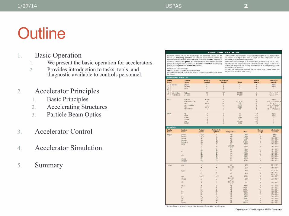
Outline 1. Basic Operation
1. We present the basic operation for accelerators. 2. Provides introduction to tasks, tools, and
diagnostic available to controls personnel.
2. Accelerator Principles 1. Basic Principles 2. Accelerating Structures 3. Particle Beam Optics
3. Accelerator Control
4. Accelerator Simulation
5. Summary
1/27/14 USPAS 2

1. What is an Accelerator? An accelerator is a machine which accelerates charged particles to very high energy.
• There are many structure types • Provide differing performance regimes • Two basic varieties are linear and circular
• There are many particles flavors • Leptons, Hadrons, Ions
• There are many applications
1/27/14 USPAS 3

1. Accelerator View: Satellite
1/27/14 USPAS 4
It can be big!
1.1 Motivation – Why Accelerators? • Accelerators are big, expensive, and high maintenance machines.
Why build them?
1/27/14 USPAS 5
¡ Some Accelerator Applications l High Energy Physics (HEP)
“How does the universe work?” more energy = more exotic particle ¡ Neutrino physics ¡ Neutron physics
l Accelerator Driven Sources (ADS) l Medical applications (e.g., proton therapy) l Neutron sources l Light sources
“..who would not want to live in a country that built such machines…”
Leon Lederman Address to U.S. Congressional concerning the construction of the Tevatron at Fermilab, Batavia, IL

1.2 Some Accelerator Facilities
USA • Fermilab, Batavia IL • Argonne, Argonne, IL • SLAC, Paolo Alto, CA • Lawerence-Berkeley, Berkeley • Brookhaven, Long Island • University of Indiana • Michigan State University • University of Maryland • MIT, Cambridge, MA • Cornell University, Ithaca, NY
1/27/14 USPAS 6
World ¡ CERN, Geneva ¡ KEK, Tsukuba, Japan ¡ PSI, Villigen, Switzerland ¡ DESY, Hamburg ¡ GSI, Darmstadt ¡ CEA, Saclay, France ¡ Rutherford-Appleton, Oxfordshire ¡ Shanghai Light Source ¡ POSTECH, Pohang, South Korea ¡ Australian Synchrotron, Melbourne
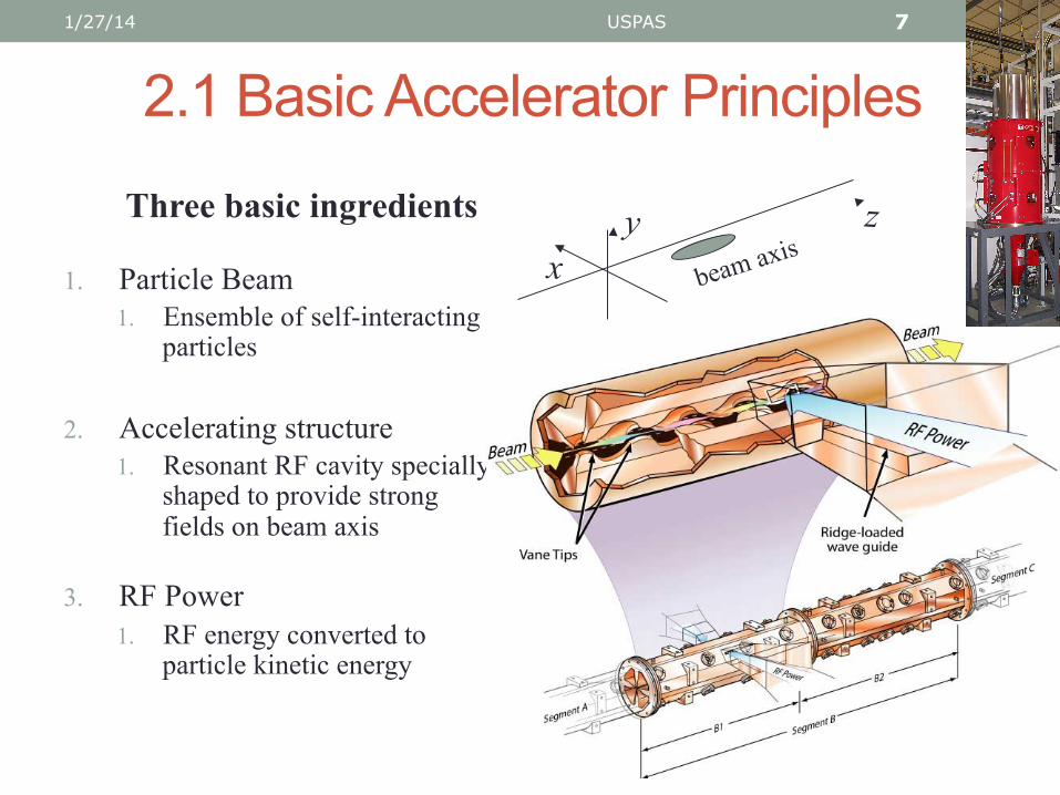
2.1 Basic Accelerator Principles
1. Particle Beam 1. Ensemble of self-interacting
particles
2. Accelerating structure 1. Resonant RF cavity specially
shaped to provide strong fields on beam axis
3. RF Power 1. RF energy converted to
particle kinetic energy
1/27/14 USPAS 7
y x
z
beam axis Three basic ingredients

2.1 Basic Accelerator Principles Mechanics
• Lorentz force law in an EM field
( )BvEF ×+= q
ΔW = F ⋅dr∫
= q E ⋅dr∫ + q dr×B ⋅drdt∫
= q E ⋅dr∫
1/27/14 USPAS 8
F – force on particle q – particle charge v – particle velocity E – electric field B – magnetic field
¡ Energy Gain ΔW from an EM field (work done on particle by field)
Only electric fields in the direction of propagation affect energy gain
• Accelerating structures create strong electric fields in the direction of propagation
0
2.2 Basic Accelerator Structures Van der Graff Acceleration
1/27/14 USPAS 9
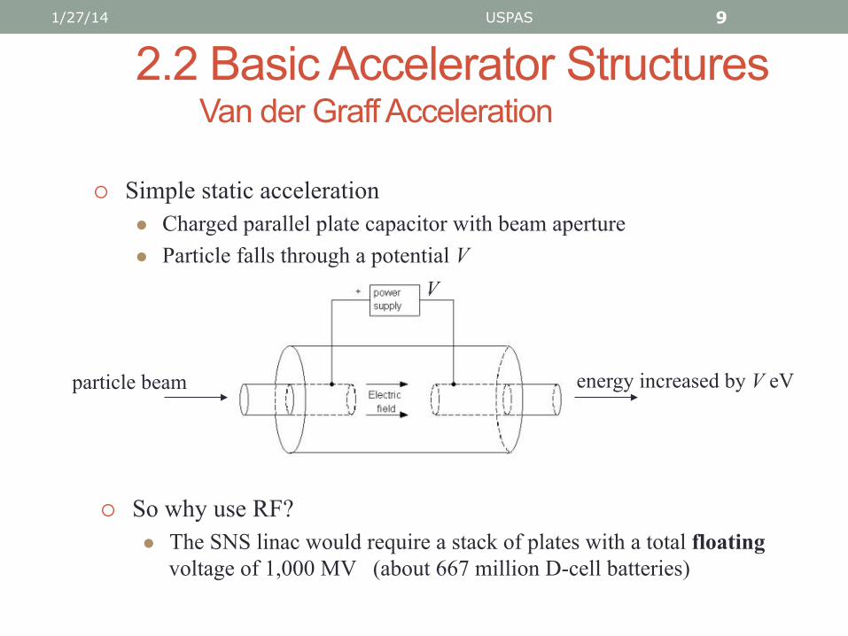
¡ Simple static acceleration l Charged parallel plate capacitor with beam aperture l Particle falls through a potential V
particle beam
V
energy increased by V eV
¡ So why use RF? l The SNS linac would require a stack of plates with a total floating
voltage of 1,000 MV (about 667 million D-cell batteries)

2.2 Accelerating Structures The Drift Tube Linac (DTL)
• DTL invented by Luis Alvarez in 1946 at Berkeley • Pillbox resonant cavity with grounded shielding tubes
1/27/14 USPAS 10
RF input
beam in
¡ RF Drive l Use fundamental TM010 mode (longitudinal E field)
¡ Beam l Beam injected after fields
established l “Drift” tubes isolate beam while
RF fields change sign
2.2 Accelerating Structures Drift Tube Linac (cont.)
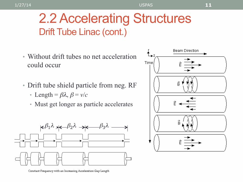
• Without drift tubes no net acceleration could occur
• Drift tube shield particle from neg. RF • Length = βλ, β = v/c • Must get longer as particle accelerates
1/27/14 USPAS 11
β1λ β2λ β3λ

2.2 Examples of Actual DTL Tanks 1/27/14 USPAS 12
CERN DTL Fermilab DTL Tank #2
2.2 Accelerating Structures SNS Facility - DTL Tanks and CCDTL Tanks
1/27/14 USPAS 13
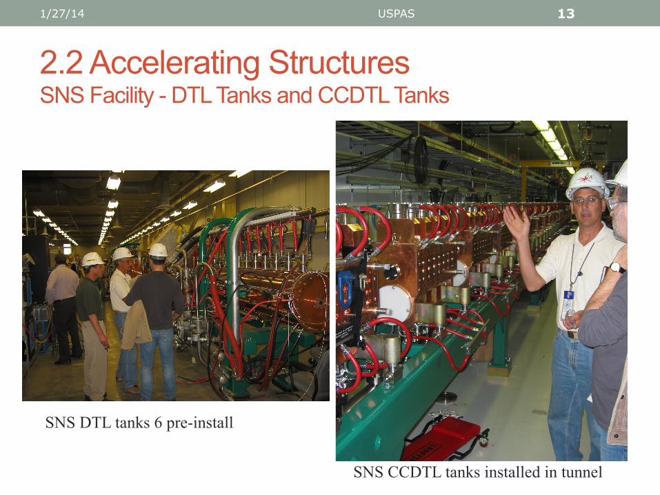
SNS DTL tanks 6 pre-install
SNS CCDTL tanks installed in tunnel
2.3 Particle Beam Optics Beam Optics with Mass
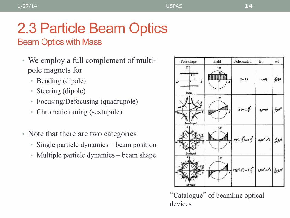
• We employ a full complement of multi-pole magnets for • Bending (dipole) • Steering (dipole) • Focusing/Defocusing (quadrupole) • Chromatic tuning (sextupole)
• Note that there are two categories • Single particle dynamics – beam position • Multiple particle dynamics – beam shape
1/27/14 USPAS 14
“Catalogue” of beamline optical devices

2.3 Particle Beam Optics Dipole Magnets
1/27/14 USPAS 15
• Dipole magnets provide • Bending of entire beamline • Focusing beam within beamline
• They also cause dispersion Particles of different energies are bend at
different angles • Analogous to a light prism
• Mass spectrograph • Beam degradation (sextupole correction)
Dipole field of a Helmholtz coil

2.3 Particle Beam Optics Quadrupole Magnets
• To maintain beam containment transverse forces must be applied
• Magnetic quadrupole “lenses” provide these transverse forces
xy
yx
qvBFqvBF
q−=
=×= orBvF
1/27/14 USPAS 16
Note for linear fields: pole face boundaries are x2 - y2 = R2
Quadrupole lenses are always focusing in one transverse plane but defocusing in the other

2.3 Particle Beam Optics Transverse Focusing (cont.)
1/27/14 USPAS 17
¡ We can achieve a net (strong) focusing by pairing quadrupoles with opposite polarities
Known as
l FODO arrangement (Focusing, Zero, Defocusing, Zero)
l Alternating Gradient (AG) focusing
x pl
ane
– de
focu
s 1st
y
plan
e –
focu
s 1st
Two quadrupoles in a FODO arrangement

2.3 Particle Beam Optics Focusing and Bending Magnets
1/27/14 USPAS 18
SNS ring quadrupole magnet
SNS ring bending dipole

3 Accelerator Control Accelerator Control Problems (Rings, Optics, etc.)
• Steering • Maintain “Golden” orbit • Collision interaction region (Simulation)
• Focusing (beam containment) • Chromatic aberrations – Off momentum particle focused differently • Envelope matching between accelerator sections – Envelope Oscillations
• Two-stream instability • Free electrons in beam pipe act as plasma stream (Simulation)
• Multiple-Impacting (Multipacting)
• Electron impacts with beam pipe creates cascade of secondary emissions (Simulation)
1/27/14 USPAS 19

3. Accelerator Control What aspects are unique to accelerators?
• Extremely tight requirements • Must steer to µm tolerance over kilometers of beamline
• Atypical control system • “Deadbeat” systems – no continuous dynamics, finite step solvable • Because v ~ c we cannot control individual beam pulses (no “state”) • Coupled spatially, upstream actions affects everything downstream
• Noise is an integral part of the system • Ground motion, alignment errors, instrument noise, etc. • Trains, waves, tides, all affect machine performance
1/27/14 USPAS 20

3. Accelerator Control Control Systems and Controls Theory
• Accelerator control does not often employ advanced controls techniques • Accelerators are build by physicists and control application by developers • Control theory the domain of research engineers
• Accelerators do not fit into the standard “plant” paradigm of controls theorists
• Experimental machines • In past, machines could be operated open loop by experience • New machine w/ requirements too stringent for manual operation
• Spallation Neutron Source (SNS) • Rare Isotope Accelerator (RIA) • International Linear Collider (ILC)
• Production facilities – desire for automation • Medical treatment facilities • Industrial accelerators
1/27/14 USPAS 21

4.1 Electron-Positron Beam Collision (Does Not Include Secondary Particle Creation)
1/27/14 USPAS 22
e-/e+ beam collision simulation, R.Ryne, J. Qiang, Lawrence Berkeley laboratory

4.1 Two Stream Instability Background Electron Cloud and Proton Beam
1/27/14 USPAS 23
Simulation by Andreas Adelmann, Paul Scherr Institute, Villigen, Swizterland
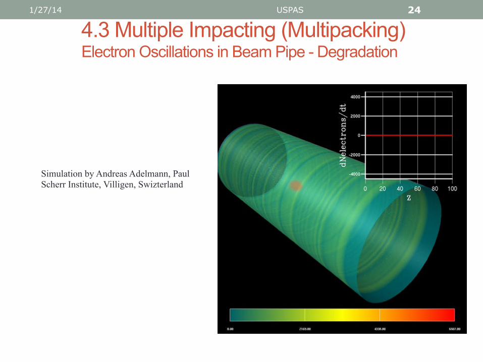
4.3 Multiple Impacting (Multipacking) Electron Oscillations in Beam Pipe - Degradation
1/27/14 USPAS 24
Simulation by Andreas Adelmann, Paul Scherr Institute, Villigen, Swizterland

5. Conclusions
• Accelerators are Big Science • Big budgets • Long-term goals • Multi-disciplinary
• Control systems • We shall see that large and complicated control
systems are necessary to operate these large machines. • Complex software systems comprise much of the
accelerator control system.
• Control and automation • Most accelerator control system are based on
Supervisory Control and Data Acquisition (SCADA) • Control theory is an open field in accelerator control.
1/27/14 USPAS 25

Supplemental • Control Problems
1/27/14 USPAS 26

4. Control Theory and Accelerators Example - Distributed Steering Algorithm
ISSUES
• We do not know state z(s) = (x, x’, y, y’, z, z’) • Have data only at BPM locations {s0,s1,s2,…} • BPMs provide only position coordinates (x,y,z) • Noise and misalignments
• Approach • State Estimator to reconstruct momentum coordinates • Multistage Network Model to approximate z(s) • Optimal Control to minimize J
1/27/14 USPAS 27

4. Control Theory and Accelerators Example - Distributed Steering Algorithm
Basic Idea - rather than minimizing beam position errors at discrete BPM locations, we minimize a functional J of the beam state z(s) throughout the beamline • The steering objective is thus defined by a functional J
• Functional J is decomposed into N terms Jn, one for each stage n
• The sub-functional for each stage n is has the form
∫+
≡1
)()(21),(
n
n
s
sn
Tnnn dsssJ zQzuz
( )Tzzyyxx 1ʹ′ʹ′ʹ′≡z
1/27/14 USPAS 28
where
Qn – symmetric, positive semi-definite matrix z(s) = n(un;s)zn

3.2 Control Theory and Accelerators Acceleration - Cavity Tuning/Klystron Phasing
Consider an RF source of form E0cos(ωt+φ0), ω = 2πf
• The phase φ(s) and energy W(s) of a particle are given by
1/27/14 USPAS 29
( )
,)()(
,)(cos)()(
00
00
∫
∫
+=
+=
s
s
z
dks
dEqZWsW
σσφφ
σσφσ
csv
ssk )(,
)(2)(where ≡≡ βλβ
π
¡ Must tune the cavity to properly shape the fields Ez(s)
¡ Must phase the klystrons to that of the particle φ(s)

4. Control Theory and Accelerators Example - Distributed Steering Algorithm
1/27/14 USPAS 30
Parameters
xi = 3 mm xi’ = 0 mrad
align = 100 m noise = 100 m
Simulation Results – Estimating state vector zn at each stage

4. Control Theory and Accelerators Example - Distributed Steering Algorithm
1/27/14 USPAS 31
Parameters
xi = 3 mm xi’ = 0 mrad
align = 250 m noise = 100 m
Simulation Results – Estimating state vector zn at each stage
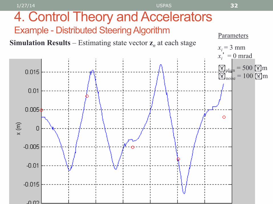
4. Control Theory and Accelerators Example - Distributed Steering Algorithm
1/27/14 USPAS 32
Parameters
xi = 3 mm xi’ = 0 mrad
align = 500 m noise = 100 m
Simulation Results – Estimating state vector zn at each stage

2.2 Accelerating Structures Super-Conducting Elliptical Cavity
• Design for very high energy > 500 MeV
• Very high peak electric fields ~100 MV/m
• One design can accommodate a range of energy values
• Less RF power but requires cryostats
1/27/14 USPAS 33
CAD drawing of a super- conducting cavity elliptic cavity with 5 “gaps”