rf control (“llrf””) development activities at major accelerator sites
TRANSCRIPT

RF Control (“LLRF””) Development Activities at
Major Accelerator Sites
Hengjie Ma
ASD-RF, 3-2-2016

OUTLINE
2
Brief Review of digital LLRF –– Essential functionalities, – Expected features from a modern system.
Examples of successful implementations– SNS @ ORNL – first large-scale deployment in the nation, – SPX @ ANL – the state of art DSP implementation
LLRF activities over the world (LLRF’15 Workshop samples)– DESY, PSI, CERN, etc.
…… If time allows Commercial solutions Issues in LLRF Development

What do we expect from a LLRF ? Essential Functions
3
CAVITYCavity Field Control
Cavity Res. Control
HPRF Protection
HP-RF
LLRF FUNC./HW STACK
Traditional list1. Cavity Field Control (“rf loops”) – fighting against all perturbations2. Cavity Resonance Control (“frequency loops”) – Tuner cntl./SEL3. Interlocks (“exception handling”)
Modern additions1. Data streaming (LLRF as rf data source, -> fast bus/network)2. Data timestamping (-> embedded EVR)3. Built-in System diagnosis (essential & possible now)4. Built-in System calibration (necessary for today’s rf specs)

Cavity Field Controller – a collection of Loops & Paths• Two basic control categories: Feedback vs. Feed Forward (FFWD)
o Feedback control is a REACTIVE ACTION -> requires no prior knowledge; delayed correctiono Feed forward control is a PREEMPTIVE ACTION -> based on prior knowledge, no delay.
• Every Control block is specially designed to suppress specific types of perturbations

Kp
PERTURBATIONS
R(s)
Set point -
+
Kly. CavityErr
rf PID loop
Y(s)Se ⋅τ
Kd
Ki/S
Ki Ki/S
LLRF control toolkit: 1. fast cavity rf feedback loop• Targets: RANDOM, RAPID, SMALL perturbations in rf, still the center-piece of a LLRF• Method: wide-band, plain PID loop -> A REACTIVE ACTION (vs. preemptive FFWD)• Usually needs feed forward to handle large dynamic range control• Digital implementation is practically required for SRF applications due to special
problems such as microphonics, Lorentz force detuning, quench protection, etc.
• Proportional control term Kd alone can only provide a “TYPE-0” control -> always has residual steady-state error• Integral control term Ki creates a “TYPE-1” system -> reduces control error to ZERO• Analog circuit cannot realize a TRUE integral term, therefore, control error remains. For NC cavities, that is just a
matter of inconvenience, but for SC cavity application, it can be a real weakness.

LLRF control toolkit : 1. fast cavity rf feedback loop (2)
• Actual data processing flow in FPGA (SNS implementation) – serialized data path for “I” and “Q” results in a very efficient resource utilization.
40MHz Inputfrom ADC
Set-point table
reg 1-Z-2
-
+
trunca-tion
del90
del90
Kp*Cs
Kp*Cs
+
+reg
Ki reg +
-reg +
-reg trunca-
tion reg
+
+reg
mux IF enhance
Feed forward bufferfor beam loading
80MHz outputto DAC
FLD
error
CORDIC
SET I
SET Q
regFWD
regRFL
regREF
Freq. Offset
Timinglogic
ProtectionInterlock
logic
VXI interfacelogic
History data buffers
Feed forward tables

OAK RIDGE NATIONAL LABORATORY
7
Hengjie Ma, 07/07Examples of LLRF Control Screens in MCR(for each of all 96 LINAC RF stations)
?
All control knobs can be operated either manually or automatically by automation sequencers (for all stations)
RF waveform display real-time update (10 Hz typical), with trace selection, zoom, pan, just like a real DSO
A real-time monitoring SC cavity condition

www.lightsource.ca
Without Beam
CLS Drive NSLSII Drive(Analog LLRF) (Digital LLRF)
SC cavity field spectrum verified with an independent spectrum analyzer
Benefits of Digital LLRF

www.lightsource.ca
250mA @ 2.9 GeV
CLS Drive NSLSII Drive
After the LLRF loop phase setting is adjusted to compensate the klystron phase, the synchrotron oscillation stopped, and the LLRF control returned to normal again
Analog LLRF vs. Digital LLRF
www.lightsource.ca
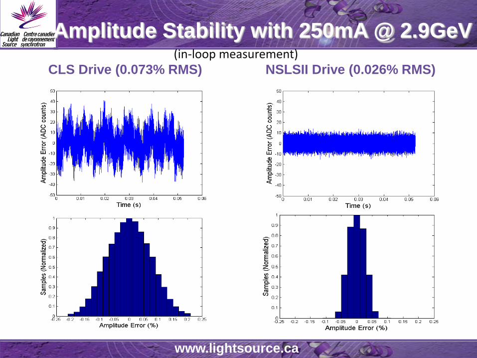
Amplitude Stability with 250mA @ 2.9GeVCLS Drive (0.073% RMS) NSLSII Drive (0.026% RMS)
(in-loop measurement)

www.lightsource.ca
Phase Stability with 250mA @ 2.9GeV
CLS Drive (0.1171o RMS) NSLSII Drive (0.019o RMS)

12 BROOKHAVEN SCIENCE ASSOCIATES
NSLS2 LLRF field at @ Canadian Light Source(300kW SRF)
•The effectiveness of LLRF feedback loop in transmitter HV harmonic level reduction measurement – confirmed with HP VSA (4 kHz span view @ 72kW)
Cavity field: open-loop Cavity field: Closed-loop

13
⋅+⋅= ∑=
−N
n
nnaz
0
2zTK1K)(G sipc
y[k]
Positional P-I control in a general form
ai = - KiTs,when i=1, 3, 5 ,7 ...orai = + KiTs,when i=0, 2, 4, 6 ...
Kp
Input x[k]I,Q,-I,-Q,I,Q...
OutputI,Q,-I,-Q,I,Q...
Z-2
Z-2
Z-2
Z-2
a1
a3
a2
aN
LLRF control toolkit: 2. Specialty feedback loops w/ FIR(can be a farm of loops)
• Purposes – to reject/suppress certain frequency components of the targeted perturbations
• Method – tailor-shape the loop passband by inserting specially designed FIR filters in the loop.
• FIR Tap spacing can be as small as 2 sampling period (Ts) as in the case of ADC noise rejection.
• Or it can be as large as one period of ring revolution as in 1-T delay feedback of circular machines.

14
LLRF control toolkit: 2. specialty feedback loop w/ FIR (2)Applation Example : SNS LINAC, Fs = 40MHz10MHz ADC “bouncing noise” rejection using a 1-tap FIR
filter to create a notch at 10MHz in the passband.
I, Q, -I, -Q,…. +
Z-1
Z-1
2I, 2Q, -2I, -2Q,….
-
Raw ADC data with noise
After noise cancellation

LLRF control toolkit: 3. Addaptive Feed Forward (AFF)
• Purpose – To suppress repetitive (predictable) perturbing events ( we know about it before time).
• Method – Adding canceling component through Feed Forward path to the output, A PREEMPTIVE ACTION (vs. delay feedback action), no transient if timed well.
• Common uses – HV ripple cancellation; beam loading compensation

LLRF control toolkit: 3. Addaptive Feed Forward (AFF)(continue)Example: Cavity filling and heavy Beam-loading compensation in SNS LINAC where the beam current is 4 times of the rf current.
Feed Forward Drive Pattern

• Conventional Resonance Control: Slow tunerwith availability of rf data from a digital LLRF, the tune motor control can be performed through a software loop by EPICS.
• A Special Resonance Control: Self-Excited Loop (SEL)to make rf generator frequency to follow the instantaneous resonance of the cavity. Essential for SRF operation.
LLRF control toolkit: 4. Cavity Resonance Controls
SEL Concept first proposed in 1978 (J. Delayen’s Ph.D thesis, Caltech).
A practical digital implementation based on a “phase-pass” scheme was developed by Jlab in 2008.
Implemented and operated with HP SRF in SPX in 2012~13.
LHC followed suit in 2015

Secrete sauce of a practical digital SEL –> phase-pass
Easy, safe operation, totally controlled rf drive power; Naturally fits in SPX LLRF implement.
LLRF control toolkit: 4. Digital Self-Excited Loop (SEL)

19
DDS, can be used to perform frequency sweep to test system frequency response.
RF FWD
CAVITY
CAVITY
RF FWD
CAVITY
Cavity started with resonance off by ~5kHz, with lots RF power, but little cavity field
Turn on output DDS, shift the output frequency by spinning the llrf output drive vector, and cavity field starts to grow
As output frequency shift reaches –5kHz, cavity field magnitude reaches a maximum, cavity resonance is found.
LLRF control toolkit: 5. Drive Output Frequency Agile
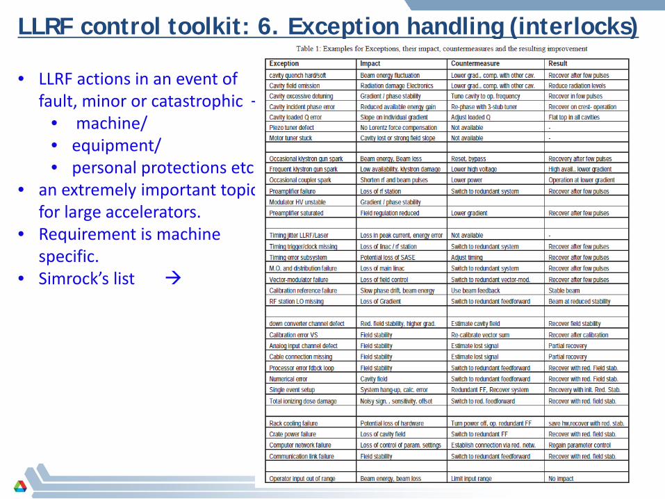
• LLRF actions in an event of fault, minor or catastrophic –
• machine/• equipment/• personal protections etc.,
• an extremely important topic for large accelerators.
• Requirement is machine specific.
• Simrock’s list
LLRF control toolkit: 6. Exception handling (interlocks)

21 BROOKHAVEN SCIENCE ASSOCIATES
• rf data buffering in an event of fault for study/investigateions (post-mortem analysis)
• (1) A trip freezes the live rf waveform data in FPGA buffer that shows what happened at exact moment of event
At partial Quench (Measured data)
Cavity Field Forward P(Sang-ho Kim, 2010 )
LLRF control toolkit: 6. Exception handling (2)

22 BROOKHAVEN SCIENCE ASSOCIATES
• Last frame of data at moment of a trip is frozen in FPGA data buffer
• Last 60 frames before the trip is recorded in the circular memory buffer in IOC
• The 60 frame of data record in IOC shows (hopefully) how the fault was led to the trip.
Example:Regulation error trip from selecting wrong gain rotation
LLRF control toolkit: 6. Exception handling (3)

LLRF control toolkit: 7. system Monitoring/diagnosis
• Live, high-resolution DSO-type rf waveform display at remote console is essential for supporting a system with a large number of rf stations.

LLRF control toolkit: 7. system Monitoring/diagnosis (continue)
• EPICS Fault-tree screen is another example of important tool for op. support.

• Purpose -- Both the rf reference and the LLRF measurement drift, often time due to ambient temperature change.
• Recent accelerators require unprecedented rf stabilities (such as 0.01%/0.01 deg.)
• The LLRF system must have a built-in calibration capability in order to meet the very tide specs.
• Methodso RF reference and its distribution must be stabilized,
involves themo-control, PLL, reflectometry, interferometry, etc. A subject by itself.
o Calibration for the phase drifts in the rf path to LLRF Performed during rf-off time ( for pulsed-rf) Performed with “pilot-tones” (for CW rf)
LLRF control toolkit: 8. rf measurement calibration

LLRF control toolkit: 8. rf measurement calibration (2)Example: SNS LINAC, pulsed-rf – method• calibration is performed in off-time between to rf pulses (time-division) by
sampling the rf reference.• Cavity rf and reference signal are sent to LLRF rack in a phase-matched cable
pair (temp. controlled), so both are subject to the same ambient temperature. • LLRF digitally demodulates the received rf and reference to get the phase
measurement of the both.• The reference phase measurement is subtracted from the cavity phase
measurement to remove the drift in the rf path (cables and circuits).• Provision was made for the option of sending a pulsed reference and the cavity
rf through the same cable in different time-slot.
e e ece
ne
SNS Linac(96 cavities)
Klystron Cavity
LLRF
High-powerProtection
Field Control FLD
FWD
REF
RFL
MPSHos
t (“IO
C”)
OUT
RF
/ IF
S
MPS
High-powerProtection
MPS
Time: Calibration pulse: RF pulse
27DOE Lehman CD-2 Review of the APS Upgrade Project 4-6 December 2012
CAVITY
LLRF-DIGITALLLRF DRV K
SYNC-HEAD
CAVITY PROBE W/ CAL-TONE
CAL-TONE INJECTION
REFERENCEFROM TIMING/
SYNCHRONIZATIONSYSTEM
TUNERTUNING COMMAND
KLY PWRBEAM
&MICROPHONICS
ANALOG FRONT-END
RF LOOP (GDR+SEL)
CALIBRATION LOOP
BEAM LOOP
TUNER LOOP
RF DATA
SPX
Inte
rlock
Inte
rfac
e
LLRF PERMIT
LLRF OK
QUENCH DETECT
INTERLOCK
LOOP
I/OC EPICSReal-Time Deflection
control
REFERENCE W/ CAL-TONE
CONTROL DATA
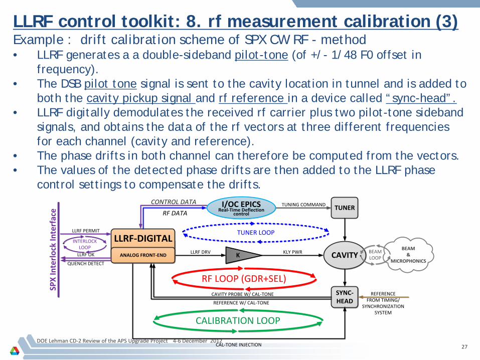
LLRF control toolkit: 8. rf measurement calibration (3)Example : drift calibration scheme of SPX CW RF - method• LLRF generates a a double-sideband pilot-tone (of +/- 1/48 F0 offset in
frequency).• The DSB pilot tone signal is sent to the cavity location in tunnel and is added to
both the cavity pickup signal and rf reference in a device called “sync-head”.• LLRF digitally demodulates the received rf carrier plus two pilot-tone sideband
signals, and obtains the data of the rf vectors at three different frequencies for each channel (cavity and reference).
• The phase drifts in both channel can therefore be computed from the vectors.• The values of the detected phase drifts are then added to the LLRF phase
control settings to compensate the drifts.

Technology developed in LBNL, demonstrated at LCLS/SLAC, and further refined for SPX application.
Phase stabilization performance of 3~15 milli-deg. was demonstrated and reported (Byrd and Huang et al., BIW’10). (within SPX rf error budget : 0.077/0.28 deg )
28
Cavity Signal
Phase Reference
Temp ControlledSync Head
Double side-bandCal Tone
driftφ
ADC
LLRF Receiver
FPGADigital Signal Processing
ADC
Phase drift detection algorithm
where
ΦREF,CAV-the calculated phase difference between cavity and ref.ΦRF_REF, ΦRF_CAV-measured phase of cavity and reference signalΦCAL_U_REF, ΦCAL_L_REF-measured phase of upper and lower side-band of Cal-Tone signal in Reference cable.ΦCAL_U_CAV, ΦCAL_L_CAV-measured phase of upper and lower side-band of Cal-Tone in Cavity field cable.
( )( )
( )2
2____
____
__,
CAVlCALREFlCAL
CAVUCALREFUCAL
CAVRFREFRECAVREF
Φ−Φ−
Φ−Φ−
Φ−Φ=Φ
DOE Lehman CD-2 Review of the APS Upgrade Project 4-6 December 2012
LLRF control toolkit: 8. rf measurement calibration (4) Example : drift calibration scheme of SPX CW RF – more details
29
DOE Lehman CD-2 Review of the APS Upgrade Project 4-6 December 2012
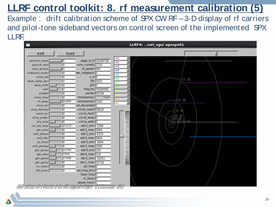
LLRF control toolkit: 8. rf measurement calibration (5) Example : drift calibration scheme of SPX CW RF – 3-D display of rf carriers and pilot-tone sideband vectors on control screen of the implemented SPX LLRF.
DOE Lehman CD-2 Review of the APS Upgrade Project 4-6 December 2012

Low Level Radio Frequency Workshop 2015hosted by Shanghai Institute of Applied Physics, Chinese Academy of Sciences
http://llrf15.csp.escience.cn/dct/page/1
92 participants, 32 institutes, 14 countries/Regions, 173 reports (sample a few)
Australia, Canada, China, EU, Germany, India, Italy, Japan, Korea, Poland,
Sweden, Switzerland, Spain, United Kingdom, United States

LLRF’15 Workshop at a Glance
31
Reports cover areas of • Facility Overview 10• Hardware 9• Systems 10• Commissioning/Operation exp. 10 • SRF 5• Phase Reference 6• Tutorials 4
International CommitteeWolfgang Hofle, CERNTomasz Plawski, JLABShinichiro Michizono, KEKLarry Doolittle, LBNLMark T. Crofford, ORNLAessandro Ratti, LBNLKevin Smith, BNLCurt Hovater, JLABMariusz Grecki, DESYBrian E Chase, FNALMatthias U Liepe, CORNELLStefan Simrock, ITERDmitry Teytelman, DIMTELZheqiao Geng, PSI
• Digital LLRF is either already used in operations or has been planned for new projects in most facilities.
• Digital LLRF is currently actively being pursued in ALS, Diamond, ESRF (?), ESS, LCLS-II, Spring-8, PSI…
Local CommitteeLocal Chair: Jianfei LiuHost: Yubin ZhaoLocal Secretary: Qiang Chang, Shenjie Zhao, Xiang Zheng, Kai Xu, Hongtao Hou, Zhigang Zhang, Zheng Li

Julien Branlard | LLRF installation and commissioning at the European XFEL | 03.11.2015 | Page 32
European XFEL Massive engineering challenge
RF parameters: Pulse length 1.4msec (750 + 650 usec) QL = 4.6e6 (½ bw = 140 Hz) 10 Hz rep. rate ΔA/A = 0.01% ΔΦ = 0.01 deg.
> LLRF: DESY in-kind 26 RF stations (808 cavities, 101
cryomodules) MicroTCA.4 LLRF system, master / slave Vector sum (32 cavities) RF control 2 piezo per cavities (1kHz tuning) Motorized cavity tuners Motorized QL, one-time fixed power ratios

Julien Branlard | LLRF installation and commissioning at the European XFEL | 03.11.2015 | Page 33
DE
FR
RU
IT
(72.7%)
(6.4%)
(5,9%)
(7,7%)
INTRODUCTION: European XFEL
3.4 km
source: http://www.xfel.eu
The European X-ray Free Electron Laser 17.5 GeV light source, Hamburg, Germany TESLA superconducting 1.3GHz RF cavities 1.4 msec pulses at 10 Hz e- beam 1.35 mA nom. - 4.5 mA max 2016: construction / commissioning 2017: first user operation
DE
Hamburg

Update on the LLRF system for the European XFEL
LLRF architecture for an RF station 34
RF station: semi-distributed LLRF system
Section Rack space Redundancy
Gun, I1, 3H1 16U Full
Linac 1 28U Full
Linac 2 28U No
Linac 3 28U No
LLRF 2013 – Oct. 1-4, Lake Tahoe, USAJulien Branlard, MSK, DESY

Update on the LLRF system for the European XFEL
The MTCA.4 LLRF system 35
AMC: Advanced Mezzanine Card RTM: Rear Transition Module 12 slots, hot swap Redundant power supply
Vector Modulator (uVM) LLRF Controller (uTC)
Down Converter (uDWC) Digitizer (uADC)
BAC
KFR
ON
T
PROBEPREF PFWD
uDAQ
uVM
LLRF 2013 – Oct. 1-4, Lake Tahoe, USAJulien Branlard, MSK, DESY
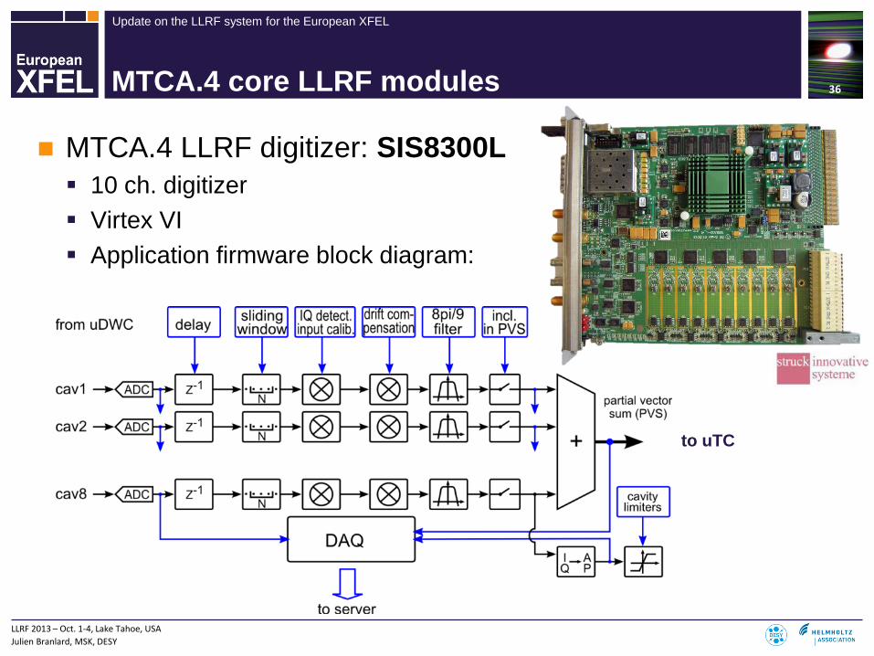
RF:1.3 GHz, IF 54 MHz, Fs: 81 MHz -> Vector-sum -> down-sampled to 9 MHz , 16-bit from DWC -> uTC
Update on the LLRF system for the European XFEL
MTCA.4 core LLRF modules
MTCA.4 LLRF digitizer: SIS8300L 10 ch. digitizer Virtex VI Application firmware block diagram:
36
to uTC
LLRF 2013 – Oct. 1-4, Lake Tahoe, USAJulien Branlard, MSK, DESY
Update on the LLRF system for the European XFEL
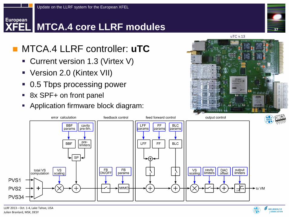
MTCA.4 core LLRF modules
MTCA.4 LLRF controller: uTC Current version 1.3 (Virtex V) Version 2.0 (Kintex VII) 0.5 Tbps processing power 8x SPF+ on front panel Application firmware block diagram:
37
uTC v.13
LLRF 2013 – Oct. 1-4, Lake Tahoe, USAJulien Branlard, MSK, DESY

Krzysztof Czuba | RF Phase Reference Distribution for the European XFEL| 03.11.2015 | Page 38
Overall Synchronization System Concept
Three complementary systems (compromise between performance and cost) Optical synchronization: sub-10fs (jitter, drift) performance, 12 links RF Coaxial distribution: sub-100fs (jitter) and sub-1ps (drift) performance, interferometers, local
distribution (44 links, ~260 reference outputs) Timing system
All systems phase synchronized to the RF Master Oscillator
GUN A1 AH1 L3 (Main LINAC)
UNDULATORS
0m 30m 40m 146m
Injector Complex Area
1 Mod. 1 Mod. 1 RFS 3 RFS 21 RFS (+3)
Exp
92m
XTIN L1-XTL
306m
L2-XTL
467m 1682m
L3-XTL
2100m 3333m
L1 L2
611m 1493m
Coax Cable, 1300 MHz
LEGEND
MLO Master Laser OscillatorCoax Cables (Interferometer), 1300 MHz
MO Master Oscillator
Coaxial RF synchronization
MLO
~131x
High Power Amplifier
Coax Cable, 216 MHz
Timing Fibers star, 100 links
Timing
MO
Optical synchronization Optical Fiber
24 TapPoints (8x3)
NOT TO SCALE!
L2RFL2RF – Laser to RF
RF reference stabilization

Update on the LLRF system for the European XFEL
LLRF Installations (front end) 39
LLRF 2013 – Oct. 1-4, Lake Tahoe, USAJulien Branlard, MSK, DESY

Julien Branlard | LLRF installation and commissioning at the European XFEL | 03.11.2015 | Page 40
TUNNEL INSTALLATION 5/5
> Incoming inspection
> Device test
> Crate installation
> Rack installation
> Tunnel installationa. Cabinet transportb. RF cabling (outer rack)c. Connections to mains, water and Ethernet, fibersd. Commissioning checklist
Ready for warm commissioning
In-tunnel LLRF installation for stable ambient temperature, and the shortest rf cable lengths.

Julien Branlard | LLRF installation and commissioning at the European XFEL | 03.11.2015 | Page 41
INSTALLATION: component inventory, testing, and installation tracking system 3/5
> Incoming inspection
> Device test
> Crate installationa. Selection of components from storageb. Upload configuration in database (KDS)c. Installation of firmware, serversd. Basic functionality checks checklist
MTCA

Julien Branlard | LLRF installation and commissioning at the European XFEL | 03.11.2015 | Page 42
INSTALLATION: testing, assembly, and storage areas
Professional cabling (in & out)
Rack Assembly and Test Area (RATA)MicroTCA Assembly Area (MASSA)
Storage

Julien Branlard | LLRF installation and commissioning at the European XFEL | 03.11.2015 | Page 43
PEOPLE
THANK YOU !谢谢
Xièxiè

Wir schaffen Wissen – heute für morgen
Automation in LLRF System
Zheqiao GengPaul Scherrer Institut (PSI), Switzerland
For LLRF15 Workshop, Shanghai, ChinaNov. 3, 2015

stm Oprational States
Initial
2. Modulator Waiting
1. Off
4. System Validating
5. Ready for RF Power
6. RF Power Ramping
7. RF Power On
8. RF Optimizing
9. RF Ready Off Beam
10. RF Ready On Beam
RF Fault
3. Standby
cmd
[modulatorInStandby]
cmd
[systemOK]
interlock [RF_RDY=1]
[AmpPhaPulShapeOK]
cmd
cmd
interlock [RF_RDY=1]
cmd
interlock [RF_RDY=1]
[RFPowerNotReached]
cmd
interlock [RF_RDY=0]
interlock [RF_RDY=0]
cmd
[systemNotOK]
[modulatorFailed]cmd
[Amp/Pha/PulShapeNotOK]
interlock [RF_RDY=1]
interlock [RF_RDY=0]
cmd
interlock [RF_RDY=1]
cmd
interlock [RF_RDY=0]
[RFPowerReachesSP]
interlock [RF_RDY=0]
System Process Example 1: RF System Startup
45
Execute Jobs: - Check system status- Correct DAC offset
Execute Jobs: - Determine and set klystron high
voltage and drive
Execute Jobs:- Calibrate loop gain and loop
phase- Adaptive feed forward
Automatic parameter setting:- Set modulator state- Set interlock system mode- Set RF switch on/off- Set feedback on/off- Set trigger delays
Execute Jobs:- Recover from RF fault trips
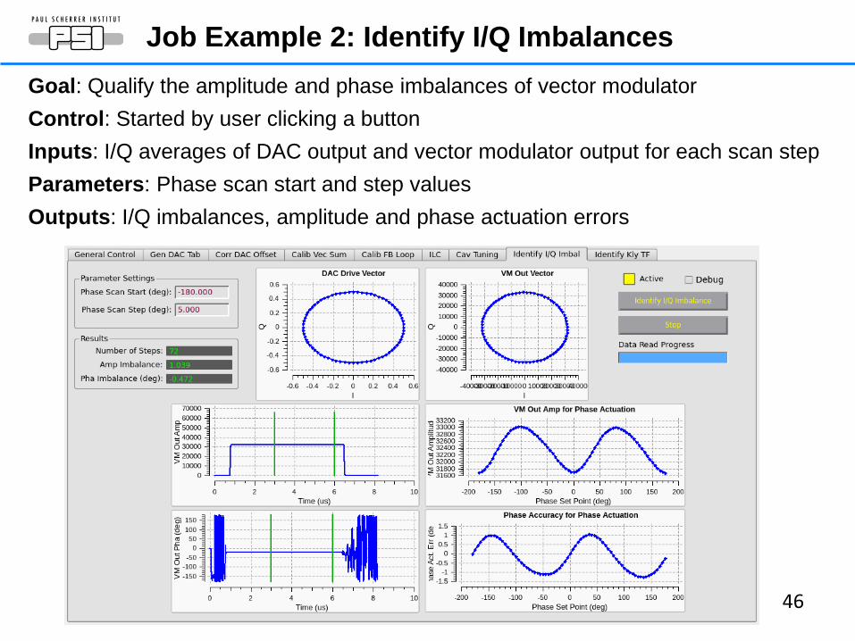
Job Example 2: Identify I/Q Imbalances
46
Goal: Qualify the amplitude and phase imbalances of vector modulatorControl: Started by user clicking a buttonInputs: I/Q averages of DAC output and vector modulator output for each scan stepParameters: Phase scan start and step valuesOutputs: I/Q imbalances, amplitude and phase actuation errors


50
VRF Control Hardware Architecture
IFC1210
IFC_TC2
FM-S14


LLRF
'15
Shan
ghai
, Chi
na
-
W.H
ofle
C
ERN
Lab
Talk
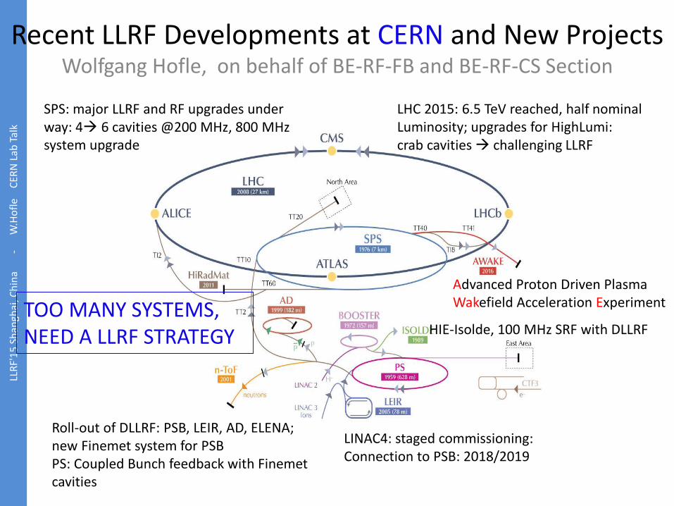
Advanced Proton Driven Plasma Wakefield Acceleration Experiment
LHC 2015: 6.5 TeV reached, half nominalLuminosity; upgrades for HighLumi:crab cavities challenging LLRF
SPS: major LLRF and RF upgrades under way: 4 6 cavities @200 MHz, 800 MHz system upgrade
Roll-out of DLLRF: PSB, LEIR, AD, ELENA; new Finemet system for PSBPS: Coupled Bunch feedback with Finemet cavities
HIE-Isolde, 100 MHz SRF with DLLRF
LINAC4: staged commissioning:Connection to PSB: 2018/2019
Recent LLRF Developments at CERN and New ProjectsWolfgang Hofle, on behalf of BE-RF-FB and BE-RF-CS Section
TOO MANY SYSTEMS, NEED A LLRF STRATEGY

Summary
CERN Focus is on Injector Upgrades during the coming years: many LLRF challenges
New Projects: AWAKE, HIE-Isolde, ELENA Make or buy ? make Platform ? VME Solution for data recording (ObsBox)
LLRF
'15
Shan
ghai
, Chi
na
-
W.H
ofle
C
ERN
Lab
Talk

LLRF
'15
Shan
ghai
, Chi
na
-
W.H
ofle
C
ERN
Lab
Talk
Linac4 LLRF
J. Noirjean, J. Galindo, D. Stellfeld, G. Hagmann, P. Baudrenghien , M. Ojeda
May 2014
Cavity Filling Ramp (50 µs)
Feedback On
Zoom
Installed on RFQ, Bunching cavities 2-3, DTL1 Observed ripple: 0.06% voltage, 0.05 deg,
without beam Transient beam loading: 1% voltage with 8
mA beam Pulse to pulse reproducibility: +- 0.05 deg
LHC LLRF type VME platform
See Talk by J. Galindo

LLRF
'15
Shan
ghai
, Chi
na
-
W.H
ofle
C
ERN
Lab
Talk
New PSB Digital LLRF system• Four operational Digital LLRF systems (Ring 1 to 4) + development ring (ring 0) which operates
Ring 4 beams in PPM with Ring 4 DLLRF.• Big RF group investment (manpower) for Meyrin machines. • PSB operational LLRF after LS1• Mandatory for PSB Finemet R&D campaign (2014-2015).• Will be deployed in LEIR in 2015 and in ELENA (Anti-proton deceleration) in 2016.
The hardware
The results
Talks by M.E. Angoletta and J. Molendijk

HIE-Isolde DLLRF (Valuch et.al)LL
RF'1
5 Sh
angh
ai, C
hina
-W
.Hof
le
CER
N L
ab Ta
lk
Front end computer
6x LLRF controller
LHC type VME Platform
• radioative ions post acceleration (low intensity)• only 16 meters long, final stage: 32 superconducting cavities (100 MHz)• challenge to control the cavity, only few Hz bandwidth• LLRF entirely digital, direct RF sampling, direct RF generation• 32 solid state RF amplifiers, 700 W each• commissioning started in summer 2015 (1 RF module with 5 cavities)• first Beam successfully accelerated last month
D. Valuch , M. Elias, M. Mician
Poster (M. Mician) and Talk (D. Valuch)

3.11.2015HIE-Isolde LLRF challenges and
commissioning. LLRF 2015 workshop Shanghai
59
Scal
ing
Rot
atio
n
Cor
dic |r|
φ
+-
+++
LimiterI’
Q’
I
QTxDAC
RF out
I
Q
|r|
φ I
QCor
dic
Gai
n Pr
op
Gai
n In
t
Rat
e lim
iter
Rat
e lim
iter
Pow
er
limit
+-
SEL offset
+-
Ref
pha
se
Cav phase
GD phase
ADC+IQ demod
Antenna
Scal
ing
Rot
atio
n
Cor
dic |r|
φ
I’
Q’
I
Q
I
Q
ADC+IQ demod
Reference
GD mag
Cav voltage
SEL mag
Rate limiterRate
limiter
HIE Isolde LLRF controller Simplified function block diagram
Challenges• Tuning plate is not extremely stiff, significant Lorentz force detuning
• Total detuning ~7 bandwidths at intended operating point• Tuner resolution ~0.1 Hz/step• Cavity has only few Hz bandwidth
• Cavity operating sequence was designed to cope with it• Start with SEL, move the frequency by tuner• Slowly lock the loops
Jlab SEL was implemented to support HIE Isolde SC cavity
Direct Phase pass

Data recording: Observation BoxLL
RF'1
5 Sh
angh
ai, C
hina
-W
.Hof
le
CER
N L
ab Ta
lk
Linux kernel
Driver Stack
Transmitter SPECFiberTransmitter SPECTransmitter SPECTransmitter SPEC
PCIe (DMA)
FESA 3RDA 3 CMW
ObsBox classJava
RDA 3
OP application
Ethernet
Computer in TN
LHC / SPS /.. Observation Box
GPGPU
RAM syscalls & sysfs
CUDA/OpenCL
VME modules with integratedTransmitters
4 x 1 / 2.5 Gb/s
Objective: Overcome limitation of VME for data transfer to fully explore diagnostic potential of the digital LLRF systems
SuperMicro’s SuperServer 6028U-TR4+ Simple PCIe FMC carrier (SPEC)
RF specific firm ware: T. Levens
A. Butterworth, M. Ojeda et al. ICALEPCS’15, WEPGF062

SSRF (“Shanghai Light Source”)

SSRF RF system of Storage

The third generation LLRF used in the storage ring
The third generation replaced the first one used in RF station II and III of Storage ring in 2015.2
Front-end board
DSP board
cPCI Controller Box
• Board with CPCI package,• 4 Channel ADC.125MSPS• 2 Channel DAC,275MSPS• 4 down-converter and one up-converter
channel• Linear is better than 60dB, isolate is better than
70dB• CPCI communication.• EPICS interface

Linac layout of SSRF Yubin Zhao, RF Group and Linac Group
LLRF in PXI crate (NI?)

LO & CLK
Subharmonic buncher Buncher A1Gun
RFforward
A2 A3 A4
RFk2forward
Klystron2Modulator
RFforward
Klystron1
Solid State Amplifier
Modulator
Pick
-up
ADC
DAC
RF Frontend
FPGA
CLK GEN
PXI System
RF
LO
IF
...
RF
LO
IF
ICS-572B
...
Rfref499.654/2997.924MHz
ADCSi
gnal
Gen
erat
orPX
I-565
0
Mot
or C
ontro
ller
PXI-7
674 LO
IF
Control FPGA
PCI Interface
Solid State Amplifier
Solid State Amplifier
Motor
Dig
italiz
erPX
I-981
6D
RFreflect
RFforward RFforward
RFforward
RFreflect
RFfo
rwar
dRF
refle
ct
Phase Shifter
Linac LLRF of SSRF
500MHz sub-buncher 6x rf=2.99GHz AS rf

ANDERS J JOHANSSON, LUND UNIVERSITY, SWEDEN
Overview and System Design for ESS LLRF Systems
5 MW Neutron source2 GeV proton linac Pulsed at 14 Hz, 2.86 ms long pulses.Rotating tungsten target

ESS Accelerator
• 1 RFQ• 3 Pillbox buncher cavities in MEBT.• 5 Drift Tube Linac sections.• 26 Superconducting spoke cavities.• 36 Superconducting medium-β cavities.• 84 Superconducting high-β cavities.
Source LEBT RFQ MEBT DTL Spokes Medium β High β HEBT Target
352.21 MHz 704.42MHzPulsed14 Hz
3.6 MeV 90 MeV 216 MeV 561 MeV 2000 MeV
62.5 mA

ESS RF power amplifiers
• One power amplifier per accelerating cavity– 2.8 MW Klystron for RFQ– 30 kW Solid State for Buncher– 2.8 MW Klystron for DTL– 2x200kW Tetrode combined for Spoke– 1.5 MW Klystron for Medium- Beta Elliptical– 1.2 MW IOT for High Beta Elliptical

Field Stability
Current requirements for regulation accuracy of the cavity field.• RFQ
+/- 0.2 % RMS amplitude+/- 0.2 o RMS*
• Normal Conducting+/- 0.2 % RMS amplitude+/- 0.2 o RMS
• Super Conducting+/- 0.1 % RMS amplitude+/- 0.1 o RMS
Relaxed requirementsfor initial 10 us.
Time
CavityField
Beam
*Relative the phase reference line. All other phase requirements relative the beam.
2.86 ms

RF Cell
LLRF:• PI-control• Adaptive feedforward• Inner klystron loop• Beam current variation
compensation

Platform: MTCA.4
• Modular design– Adaptable to different
cavities.– Facilitates incremental
upgrades– Simplifies end of life
management• Temperature controlled rack
LLRF is in-kind contribution ( DESY and others)

Status• Two test benches up and
running at Lund University– 352.21 MHz– 704.42 MHz
• Test benches controlled from a central ”control room” computer and screens.
• One prototype running at Freia test hall at Uppsala University.
After 4~5 years…

Linear Coherent Light Source – II (LCLS–II)• Collaboration with SLAC, FNAL, JLAB • System architecture design
• Modular NAD (network attached device) design
• Separation of high precision receiver and RF drive station
• Common FPGA boards in modules• End-to-end simulation
Digital RF control at LBNL, L. Doolittle, G. Huang, C. Serrano, et. al
• LCLS-II is just like XFEL, except ...• CW instead of pulsed• 20 Hz bandwidth SRF cavity, instead of 800 Hz
bandwidth• Goal is still 0.01, 0.01%• Fast beam-based feedback is not part of LCLS-
II baseline, for cost reasons• As of September 2014, the baseline design
changed from one Klystron per 48 cavities,• to a 3.8 kW Solid State Amp (SSA) per cavity
(single-source single-cavity, SSSC).

LCLS–II LLRF
In 3 enclosuresCHASSIS
CHASSIS
ATCA

LCLS–II LLRF
FPGA DSP as an analog component
DSP “Real” analognoise yes yes1=f noise no yesdrift no yestemp. coe. no yesgroup delay yes yessaturation yes yesdistortion no yescrosstalk no yesimperfect cal. No yespower dissipation yes yessimulatable yes yesremote updates yes no

Summary
76
Over a decade and half (since 2001), a lot of progress has been made, and basic techniques have been learnt.
LLRF community has become more mature in both– Using proven techniques/designs, and – Choosing Pragmatic Implementations
R&D in reference/calibration continues to be the focus Development of the more realistic SRF cavity models
in FPGA is being pursued, which would be very useful for SRF systems.
DOE Lehman CD-2 Review of the APS Upgrade Project 4-6 December 2012
Thanks for your attention

A example of Commercial LLRF Solutions
77
LLRF-9 from Dimtel Users : ELSA, ANKA, SESAME. The unit has also been demonstrated in
Diamond booster and LNLS booster and storage ring.