control of soil moisture with radio frequency in a...
TRANSCRIPT
Turk J Elec Eng & Comp Sci
(2015) 23: 447 – 458
c⃝ TUBITAK
doi:10.3906/elk-1302-22
Turkish Journal of Electrical Engineering & Computer Sciences
http :// journa l s . tub i tak .gov . t r/e lektr ik/
Research Article
Control of soil moisture with radio frequency in a photovoltaic-powered drip
irrigation system
Mahir DURSUN1,∗, Semih OZDEN2
1Department of Electrical-Electronics Engineering, Faculty of Technology, Gazi University, Ankara, Turkey2Department of Electrical and Energy, OSTIM Vocational School, Gazi University, Ankara, Turkey
Received: 04.02.2013 • Accepted: 28.03.2013 • Published Online: 23.02.2015 • Printed: 20.03.2015
Abstract: Solar-powered irrigation systems are becoming increasingly widespread. However, the initial setup costs of
these systems are very high. To reduce these costs, both the energy usage and the prevention of losses from irrigation
systems are very important. In this study, a drip irrigation control system of 1000 dwarf cherry trees was controlled using
soil moisture sensors in order to prevent excessive water consumption and energy losses in a solar-powered irrigation
system. The control system comprises units that are energized with solar panels, and the flow of information is
implemented via radio frequency. Thus, by removing the cables that create difficulties in the cultivation of gardens,
both the easy cultivation of the soil is enabled and cable costs are eliminated. The portability of the units is enabled
by using solar energy; thus, units might be mounted wherever the user wishes. It has been indicated that the moisture
of the application area varies depending on the data obtained regarding volumetric water content and the defined area
in need of irrigation. In this way, there are reductions in the dependence on instantaneous water demand, the amount
of water to be pumped, and the energy requirements needed for irrigation. In addition, pump power and the power of
the motor that drives the pump are also reduced. According to the obtained measurement values, it was calculated that
hourly water demand decreased by 36%. Thus, the numbers of solar panels, electrical machines, batteries, and units of
power control that supply all the energy of the system and constitute a large part of the initial setup costs are reduced
at the same rate by means of the applied technique. Thanks to the developed site-specific irrigation system, unnecessary
energy consumption was avoided. Along with the elimination of excessive and unnecessary irrigation, problems with
trees were also eliminated.
Key words: Soil moisture sensor, wireless sensor networks, drip irrigation, control of soil moisture
1. Introduction
The consumption and need for water and energy are 2 of the most important issues of the world in which we
live. Human nutrition, meeting basic needs, and watering plants cannot be considered without water; water
cannot be considered without energy. Classical flood irrigation systems are known as wild irrigation; they use
an excessive amount of water and cause the growth of weeds. These drawbacks can be removed by the use of
drip irrigation systems applicable solely to the areas where the plants and roots are located.
Solar-powered drip irrigation systems are becoming very common. However, the initial installation costs
of these systems are very high [1]. In order to reduce these costs, both energy usage and preventing losses in
the irrigation system are very important.
An equal amount of water is applied to all trees in classic drip irrigation systems. However, soil moisture
∗Correspondence: [email protected]
447
DURSUN and OZDEN/Turk J Elec Eng & Comp Sci
values vary. Furthermore, the irrigation of trees is dependent on the producer’s skill and knowledge. Water
needs may vary according to the age and characteristics of the trees and the type, variation, and structure
of the soil [2]. Giving an excessive amount of water to trees means greater energy consumption. This not
only increases the cost of the solar-powered systems unnecessarily but also causes salinization and increases the
consumption of both water and energy. Moreover, it also reduces crop yields by leading to the decay of tree
roots. Not giving enough water may cause a reduction in the product efficiency obtained from the trees and
may cause the trees to wither. Irrigation according to the properties of the soil and the trees eliminates these
disadvantages. Site-specific irrigation not only reduces operating costs (i.e. energy, water) but also increases
product efficiency. Nowadays, the sensor-based site-specific irrigation system is the most emphasized [3–6].
For the last 20 years, with the development of wireless technologies, many researchers have focused their
studies on sensor-based automatic irrigation to reduce water usage [7,8]. Soil moisture content measurements
are carried out using soil moisture sensors in the majority of sensor-based site-specific irrigation. Depending on
the soil moisture content, the areas to be irrigated are determined and water flow is controlled accordingly. This
is done by switching electric valves (electrovalves) into open/closed positions based on the information received
from these sensors. The communication between the sensors and the valves can be wired or wireless. Wiredcommunication results in both an increase in cost and the loss of information over long distances. Using wireless
sensor networks offers many advantages, such as eliminating cable and cable installation costs, providing easy
and portable assembly (especially in large areas), and the fact that they do not require maintenance [9–11].
After wireless technology began to be used in the agricultural field, various types of controllers and protocols
were tested. Studies have been conducted for controlling precision irrigation systems using technologies such
as microprocessors, field-programmable gate array, GSM/GPRS, and Bluetooth in this field [10,12–15]. The
biggest drawback of high frequency (2.4 GHz and above), which has provided faster and more reliable flow of
information in recent studies, is the high installation cost [16–18].
Li et al., who used wired communication between a central unit and sensor units, evaluated the quality of
wired communications and the differences between values obtained by burying sensors measuring soil moisture
and temperature at the same time at different depths [19]. Cardenas-Lailhacar et al. compared the performance
of different types of sensors in different terrains and determined that soil moisture sensors reduce water usage
[20,21]. In studies comparing sensors using various measurement techniques in a lab environment, it was
determined that sensors measuring volumetric water content give more reliable results [22,23]. In the past few
years, the energy consumption and energy usage of various sensor types, communication protocols, equipment,
and techniques have been investigated. Reducing the total energy consumption of the system reduces the
installation costs of the systems, which are quite high for users. For this purpose, in wireless sensor-based
site-specific irrigation work where energy demands are often met by solar energy, studies have been conducted
on developing protocols that reduce energy consumption and select products with low energy consumption in
order to reduce costs [18,24].
In this study of a solar-powered irrigation system where energy demands are met by solar energy, the
difference from previous studies is that a site-specific drip irrigation system depending on soil moisture was
designed; instant information about soil moisture was taken by radio frequency (RF) and used in the irrigation
of cherry trees. Thus, both energy and water consumption were reduced by controlling soil moisture. Moreover,
since a less powerful pump would be enough to provide irrigation, the solar panels and motor power required for
the initial setup were reduced. Software was developed for this control, and control of the valves was achieved
by comparing instant soil moisture values and user-specified threshold humidity values. Volumetric soil water
448
DURSUN and OZDEN/Turk J Elec Eng & Comp Sci
content (VWC) information was detected by a sensor unit and sent to the central unit. Moisture information
obtained by the central unit was transferred to a computer with a serial port. Depending on the user-defined
VWC threshold value in the developed software, open/closed positions of the valves were determined and this
information was sent to the related valve unit. The flow of the water coming from the main irrigation pipe
was provided via electrovalves mounted on each lateral. Communication among the units in the system was
performed using low-cost RF modules working at 434 MHz; thus, cost reduction was achieved.
2. Design of the soil moisture measurement system with radio frequency
The study was carried out on dwarf cherry trees across 0.8 ha located in the Zile district of Tokat Province
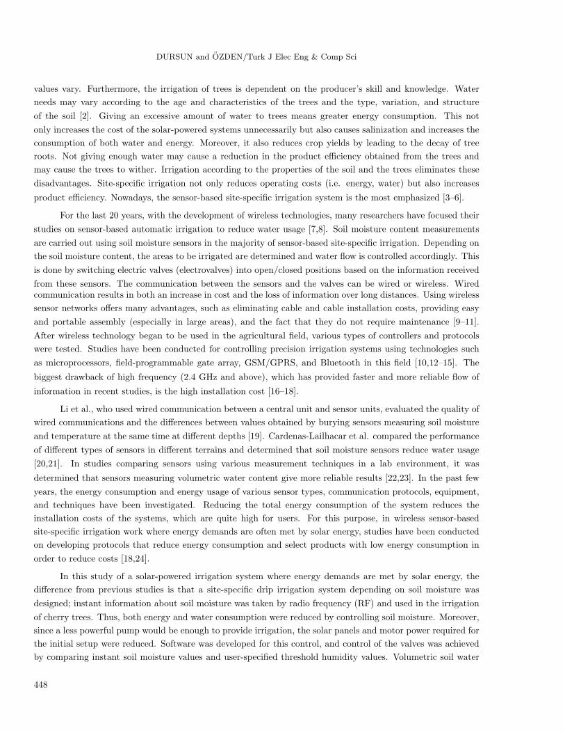
in Turkey at 40◦10 ′48.12” N, 35◦ 51 ′59.21” E. An overview of the applied area-installed system of this study
is shown in Figure 1. The water taken from the dam lake by Pump 1 was sent to a 100-t tank located
approximately 200 m away. Stored water was added to the main drip pipe via Pump 2 by passing it through the
filters protecting the drip irrigation system. Twenty-four panels, each with a power of 80 W making 1.92 kW
in total, were installed to provide the energy that was needed for each pump. Additionally, a 6240-W battery
bank was added to Pump 2 to provide energy for the motor in the event of low solar irradiation.
Pump-1
Dam Lake
Filters
Pump-2
Laterals
Valve Unit
Control Unit
SensorUnit
Figure 1. Overview of the applied area installed system.
Drippers were connected to the main pipe and mounted to 14 lateral pipes of 50.8 cm each in parallel
positions. The moisture values created by the water obtained from the drippers were detected via the analog
channel of a microcontroller using soil moisture sensors. Soil moisture information determined in the sensor
unit was sent to the central unit together with encoded information containing sensor information. The values
obtained from the central unit were transferred to the computer; by evaluating them depending on the threshold
determined by the developed software, the data for open/closed positions of the valves were transferred to the
relevant valve units. When the transferred information reached the valve unit, the valve position was changed.
In addition, moisture information transferred to the computer via the central unit was saved to a file with date,
time, and sensor number. Thus, the moisture information of the garden was made available for the user at any
time. By meeting the energy requirements of the units via the solar panels of each unit, portability of the units
449
DURSUN and OZDEN/Turk J Elec Eng & Comp Sci
was achieved; cable costs were eliminated by using RF in the information flow among units. In addition to the
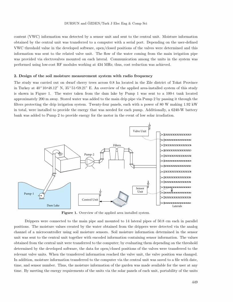
solar panel, a battery was added to the valve unit. An overview of the solar panels is shown in Figure 2.
2.1. RF module
In this study, a UDEA brand UFM-M11 model RF module (RFM) was used. To this low-power module
using the frequency of 434 MHz, a UGPA-434 model antenna, which is capable of multicasting and capable of
communicating up to 400–500 m in an open area, was added. For modulation, the module uses the frequency
shift keying method. Power consumption of the module, with a maximum output power of 10 dBm, was 10 mW
at 434 MHz. During transmission and receiving, 30 mA current and 17 mA current were drawn, respectively.
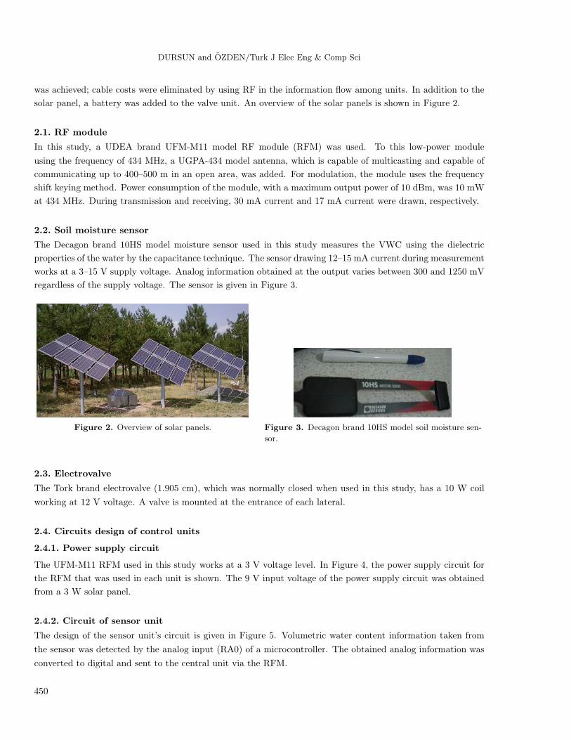
2.2. Soil moisture sensor
The Decagon brand 10HS model moisture sensor used in this study measures the VWC using the dielectric
properties of the water by the capacitance technique. The sensor drawing 12–15 mA current during measurement
works at a 3–15 V supply voltage. Analog information obtained at the output varies between 300 and 1250 mV
regardless of the supply voltage. The sensor is given in Figure 3.
Figure 2. Overview of solar panels. Figure 3. Decagon brand 10HS model soil moisture sen-
sor.
2.3. Electrovalve
The Tork brand electrovalve (1.905 cm), which was normally closed when used in this study, has a 10 W coil
working at 12 V voltage. A valve is mounted at the entrance of each lateral.
2.4. Circuits design of control units
2.4.1. Power supply circuit
The UFM-M11 RFM used in this study works at a 3 V voltage level. In Figure 4, the power supply circuit for
the RFM that was used in each unit is shown. The 9 V input voltage of the power supply circuit was obtained
from a 3 W solar panel.
2.4.2. Circuit of sensor unit
The design of the sensor unit’s circuit is given in Figure 5. Volumetric water content information taken from
the sensor was detected by the analog input (RA0) of a microcontroller. The obtained analog information was
converted to digital and sent to the central unit via the RFM.
450

DURSUN and OZDEN/Turk J Elec Eng & Comp Sci
Figure 4. Power supply circuit of RFM.
Figure 5. Circuit of sensor unit.
In order to establish communication between the microcontroller with an output of TTL level and RFM
with an input of 3 V, a level converter circuit was designed and applied successfully.
The location of the sensor placed underground and a view of the mounted sensor unit in the application
area are given in Figures 6 and 7, respectively.
Figure 6. Installation location of soil moisture sensor underground.
451
DURSUN and OZDEN/Turk J Elec Eng & Comp Sci
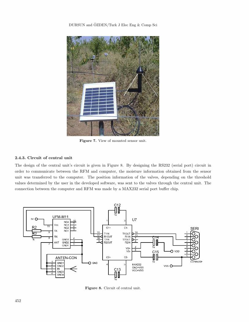
Figure 7. View of mounted sensor unit.
2.4.3. Circuit of central unit
The design of the central unit’s circuit is given in Figure 8. By designing the RS232 (serial port) circuit in
order to communicate between the RFM and computer, the moisture information obtained from the sensor
unit was transferred to the computer. The position information of the valves, depending on the threshold
values determined by the user in the developed software, was sent to the valves through the central unit. The
connection between the computer and RFM was made by a MAX232 serial port buffer chip.
Figure 8. Circuit of central unit.
452
DURSUN and OZDEN/Turk J Elec Eng & Comp Sci
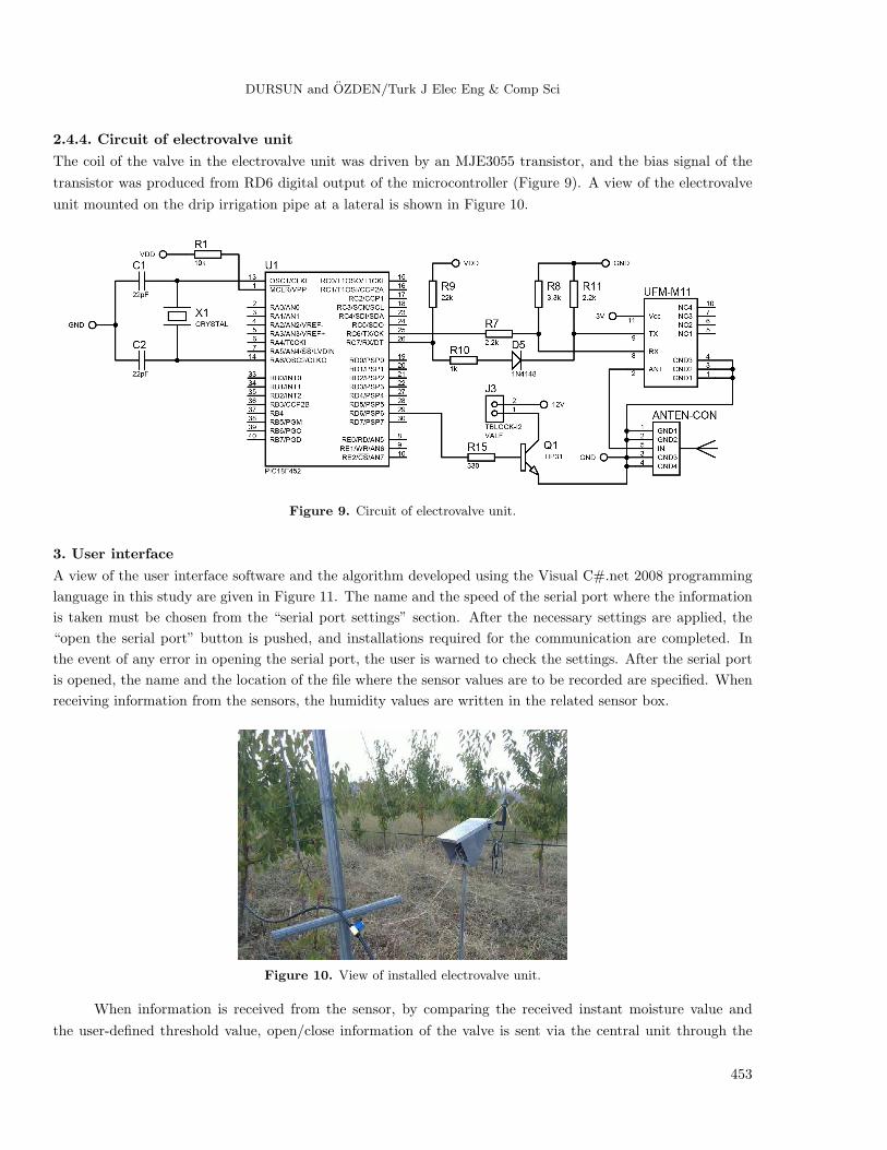
2.4.4. Circuit of electrovalve unit
The coil of the valve in the electrovalve unit was driven by an MJE3055 transistor, and the bias signal of the
transistor was produced from RD6 digital output of the microcontroller (Figure 9). A view of the electrovalve
unit mounted on the drip irrigation pipe at a lateral is shown in Figure 10.
Figure 9. Circuit of electrovalve unit.
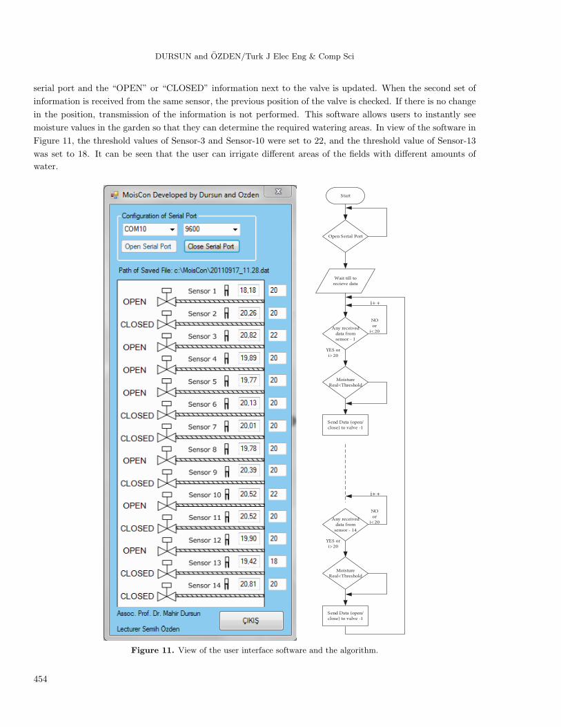
3. User interface
A view of the user interface software and the algorithm developed using the Visual C#.net 2008 programming
language in this study are given in Figure 11. The name and the speed of the serial port where the information
is taken must be chosen from the “serial port settings” section. After the necessary settings are applied, the
“open the serial port” button is pushed, and installations required for the communication are completed. In
the event of any error in opening the serial port, the user is warned to check the settings. After the serial port
is opened, the name and the location of the file where the sensor values are to be recorded are specified. When
receiving information from the sensors, the humidity values are written in the related sensor box.
Figure 10. View of installed electrovalve unit.
When information is received from the sensor, by comparing the received instant moisture value and
the user-defined threshold value, open/close information of the valve is sent via the central unit through the
453
DURSUN and OZDEN/Turk J Elec Eng & Comp Sci
serial port and the “OPEN” or “CLOSED” information next to the valve is updated. When the second set of
information is received from the same sensor, the previous position of the valve is checked. If there is no change
in the position, transmission of the information is not performed. This software allows users to instantly see
moisture values in the garden so that they can determine the required watering areas. In view of the software in
Figure 11, the threshold values of Sensor-3 and Sensor-10 were set to 22, and the threshold value of Sensor-13
was set to 18. It can be seen that the user can irrigate different areas of the fields with different amounts of
water.
Start
Open Serial Port
Wait till torecieve data
Any receiveddata fromsensor - 1
i++
NO or
i< 20
YES or i> 20
MoistureReal<Threshold
Send Data (open/close) to valve -1
Any receiveddata from
sensor - 14
i++
NO or
i< 20
YES or i> 20
MoistureReal<Threshold
Send Data (open/close) to valve -1
Figure 11. View of the user interface software and the algorithm.
454
DURSUN and OZDEN/Turk J Elec Eng & Comp Sci
4. Experimental results
In this study, recording of the soil moisture values with the developed software was started at 0930 hours; the
irrigation pump started to run at 1130 hours. The irrigation process was carried out by ensuring that the pump
remained open for approximately 2 h. The recording process continued up to 1800 hours. By recording moisture
values every 5 s over a total of 510 min, 6200 pieces of data in total were obtained.
In the application, 3 drippers with 2 L/h capacity were installed on each tree. The hourly water demand
of 1000 trees is 6000 L. Based on the experimental results, it was calculated that 360 trees were excessively
irrigated during an hour. Therefore, in total, 2160 L of water gain per hour was achieved with the developed
system. Thus, by recording the application results of the developed system and classical systems and comparing
them, it was observed that water consumption was reduced by 36% using the new system.
Analog data obtained from soil moisture sensors were converted into digital information via microcon-
trollers. Digital moisture information was converted into volumetric water content with a formula given by the
manufacturer. The conversion formula is given in Eq. (1). ADC in the formula represents the analog value in
the mV type in the output of the sensor.
VWC = 1.17 ∗ 10−9 ∗ADC3 − 3.95 ∗ 10−6 ∗ADC2 + 4.90 ∗ 10−3 ∗ADC − 1.92. (1)
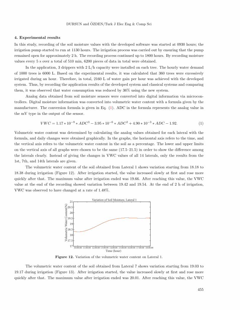
Volumetric water content was determined by calculating the analog values obtained for each lateral with the
formula, and daily changes were obtained graphically. In the graphs, the horizontal axis refers to the time, and
the vertical axis refers to the volumetric water content in the soil as a percentage. The lower and upper limits
on the vertical axis of all graphs were chosen to be the same (17.5–21.5) in order to show the difference among
the laterals clearly. Instead of giving the changes in VWC values of all 14 laterals, only the results from the
1st, 7th, and 14th laterals are given.
The volumetric water content of the soil obtained from Lateral 1 shows variation starting from 18.18 to
18.38 during irrigation (Figure 12). After irrigation started, the value increased slowly at first and rose more
quickly after that. The maximum value after irrigation ended was 19.66. After reaching this value, the VWC
value at the end of the recording showed variation between 19.42 and 19.54. At the end of 2 h of irrigation,
VWC was observed to have changed at a rate of 1.48%.
10:00:00 11:00:00 12:00:00 13:00:00 14:00:00 15:00:00 16:00:00 17:00:00 18:00:0017
17.5
18
18.5
19
19.5
20
20.5
21Variation of Soil Moisture, Lateral 1
Time (hour)
Vo
lum
etri
c W
ater
Co
nte
nt(
%)
Figure 12. Variation of the volumetric water content on Lateral 1.
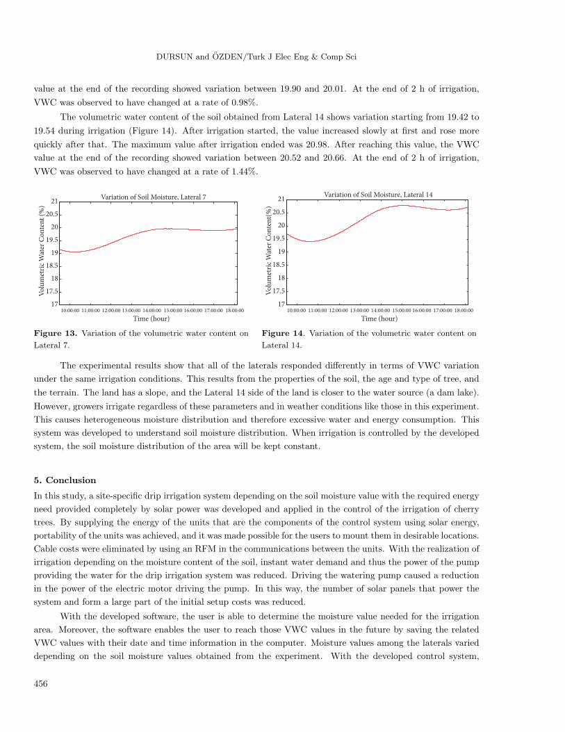
The volumetric water content of the soil obtained from Lateral 7 shows variation starting from 19.03 to
19.17 during irrigation (Figure 13). After irrigation started, the value increased slowly at first and rose more
quickly after that. The maximum value after irrigation ended was 20.01. After reaching this value, the VWC
455
DURSUN and OZDEN/Turk J Elec Eng & Comp Sci
value at the end of the recording showed variation between 19.90 and 20.01. At the end of 2 h of irrigation,
VWC was observed to have changed at a rate of 0.98%.
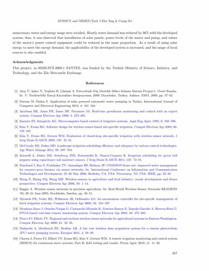
The volumetric water content of the soil obtained from Lateral 14 shows variation starting from 19.42 to
19.54 during irrigation (Figure 14). After irrigation started, the value increased slowly at first and rose more
quickly after that. The maximum value after irrigation ended was 20.98. After reaching this value, the VWC
value at the end of the recording showed variation between 20.52 and 20.66. At the end of 2 h of irrigation,
VWC was observed to have changed at a rate of 1.44%.
10:00:00 11:00:00 12:00:00 13:00:00 14:00:00 15:00:00 16:00:00 17:00:00 18:00:0017
17.5
18
18.5
19
19.5
20
20.5
21
Time (hour)
Vo
lum
etri
c W
ater
Co
nte
nt
(%)
Variation of Soil Moisture, Lateral 7
10:00:00 11:00:00 12:00:00 13:00:00 14:00:00 15:00:00 16:00:00 17:00:00 18:00:0017
17.5
18
18.5
19
19.5
20
20.5
21
Time (hour)
Vo
lum
etri
c W
ater
Co
nte
nt(
%)
Variation of Soil Moisture, Lateral 14
Figure 13. Variation of the volumetric water content on
Lateral 7.
Figure 14. Variation of the volumetric water content on
Lateral 14.
The experimental results show that all of the laterals responded differently in terms of VWC variation
under the same irrigation conditions. This results from the properties of the soil, the age and type of tree, and
the terrain. The land has a slope, and the Lateral 14 side of the land is closer to the water source (a dam lake).
However, growers irrigate regardless of these parameters and in weather conditions like those in this experiment.
This causes heterogeneous moisture distribution and therefore excessive water and energy consumption. This
system was developed to understand soil moisture distribution. When irrigation is controlled by the developed
system, the soil moisture distribution of the area will be kept constant.
5. Conclusion
In this study, a site-specific drip irrigation system depending on the soil moisture value with the required energy
need provided completely by solar power was developed and applied in the control of the irrigation of cherry
trees. By supplying the energy of the units that are the components of the control system using solar energy,
portability of the units was achieved, and it was made possible for the users to mount them in desirable locations.
Cable costs were eliminated by using an RFM in the communications between the units. With the realization of
irrigation depending on the moisture content of the soil, instant water demand and thus the power of the pump
providing the water for the drip irrigation system was reduced. Driving the watering pump caused a reduction
in the power of the electric motor driving the pump. In this way, the number of solar panels that power the
system and form a large part of the initial setup costs was reduced.
With the developed software, the user is able to determine the moisture value needed for the irrigation
area. Moreover, the software enables the user to reach those VWC values in the future by saving the related
VWC values with their date and time information in the computer. Moisture values among the laterals varied
depending on the soil moisture values obtained from the experiment. With the developed control system,
456
DURSUN and OZDEN/Turk J Elec Eng & Comp Sci
unnecessary water and energy usage were avoided. Hourly water demand was reduced by 36% with the developed
system; thus, it was observed that installation of solar panels, power levels of the motor and pump, and values
of the motor’s power control equipment could be reduced in the same proportion. As a result of using solar
energy to meet the energy demand, the applicability of the developed system is increased, and the usage of local
sources is also enabled.
Acknowledgments
This project, as 00228.STZ.2008-1 SANTEZ, was funded by the Turkish Ministry of Science, Industry, and
Technology, and the Zile Mercantile Exchange.
References
[1] Atay U, Isıker Y, Yesilata B, Cıkman A. Fotovoltaik Guc Destekli Mikro Sulama Sistemi Projesi-1: Genel Esaslar.
In: V. Yenilenebilir Enerji Kaynakları Sempozyumu; 2009; Diyarbakır, Turkey. Ankara: EMO, 2009, pp. 57–62.
[2] Dursun M, Ozden S. Application of solar powered automatic water pumping in Turkey. International Journal of
Computer and Electrical Engineering 2012; 4: 161–164.
[3] Jacobson BK, Jones PH, Jones JW, Paramore JA. Real-time greenhouse monitoring and control with an expert
system. Comput Electron Agr 1989; 3: 273–285.
[4] Zazueta FS, Smajstrla AG. Microcomputer-based control of irrigation systems. Appl Eng Agric 1992; 8: 593–596.
[5] Kim Y, Evans RG. Software design for wireless sensor-based site-specific irrigation. Comput Electron Agr 2009; 66:
159–165.
[6] Kim Y, Evans RG, Iversen WM. Evaluation of closed-loop site-specific irrigation with wireless sensor network. J
Irrig Drain E-ASCE 2009; 135: 25–31.
[7] McCready MS, Dukes MD. Landscape irrigation scheduling efficiency and adequacy by various control technologies.
Agr Water Manage 2011; 98: 697–704.
[8] Zotarelli L, Dukes MD, Scholberg JMS, Femminella K, Munoz-Carpena R. Irrigation scheduling for green bell
peppers using capacitance soil moisture sensors. J Irrig Drain E-ASCE 2011; 137: 73–81.
[9] Panchard J, Rao S, Prabhakar TV, Jamadagni HS, Hubaux JP. COMMON-Sense net: improved water management
for resource-poor farmers via sensor networks. In: International Conference on Information and Communication
Technologies and Development; 25–26 May 2006; Berkeley, CA, USA. Piscataway, NJ, USA: IEEE, pp. 22–33.
[10] Wang N, Zhang NQ, Wang MH. Wireless sensors in agriculture and food industry: recent development and future
perspective. Comput Electron Agr 2006; 50: 1–14.
[11] Baggio A. Wireless sensor networks in precision agriculture. In: Real-World Wireless Sensor Networks REALWSN
‘05; 20–21 June 2005; Stockholm, Sweden, pp. 50–51.
[12] Miranda FR, Yoder RE, Wilkerson JB, Odhiambo LO. An autonomous controller for site-specific management of
fixed irrigation systems. Comput Electron Agr 2005; 48: 183–197.
[13] Mendoza-Jasso J, Ornelas-Vargas G, Castaneda-Miranda R, Ventura-Ramos E, Zepeda-Garrido A, Herrera-Ruiz G.
FPGA-based real-time remote monitoring system. Comput Electron Agr 2005; 49: 272–285.
[14] Pierce FJ, Elliott TV. Regional and on-farm wireless sensor networks for agricultural systems in EasternWashington.
Comput Electron Agr 2008; 61: 32–43.
[15] Mahjoubi A, Mechlouch RF, Brahim AB. A low cost wireless data acquisition system for a remote photovoltaic
(PV) water pumping system. Energies 2011; 4: 68–89.
[16] Chavez J, Pierce FJ, Elliott TV, Evans RG, Kim Y, Iversen WM. A remote irrigation monitoring and control system
(RIMCS) for continuous move systems. Part B: field testing and results. Precis Agric 2010; 11: 11–26.
457
DURSUN and OZDEN/Turk J Elec Eng & Comp Sci
[17] Demirkol I, Ersoy C, Alagoz F. MAC protocols for wireless sensor networks: a survey. IEEE Commun Mag 2006;
44: 115–121.
[18] Lajara R, Alberola J, Pelegri-Sebastia J. A solar energy powered autonomous wireless actuator node for irrigation
systems. Sensors 2011; 11: 329–340.
[19] Li Z, Wang N, Hong TS, Franzen A, Li JNA. Closed-loop drip irrigation control using a hybrid wireless sensor and
actuator network. Science China–Information Sciences 2011; 54: 577–588.
[20] Cardenas-Lailhacar B, Dukes MD. Precision of soil moisture sensor irrigation controllers under field conditions. Agr
Water Manage 2010; 97: 666–672.
[21] Cardenas-Lailhacar B, Dukes MD, Miller GL. Sensor-based automation of irrigation on Bermuda grass during dry
weather conditions. J Irrig Drain E-ASCE 2010; 136: 184–193.
[22] Pardossi A, Incrocci L, Incrocci G, Malorgio F, Battista P, Bacci L, Rapi B, Marzialetti P, Hemming J, Balendonck
J. Root zone sensors for irrigation management in intensive agriculture. Sensors 2009; 9: 2809–2835.
[23] Chavez JL, Varble JL, Andales AA. Performance evaluation of selected soil moisture sensors. In: 23rd Annual
Central Plains Irrigation Conference; 22–23 February 2011; Burlington, CO, USA. Colby, KS, USA: CPIA, pp.
29–38.
[24] Sudha MN, Valarmathi ML, Babu AS. Energy efficient data transmission in automatic irrigation system using
wireless sensor networks. Comput Electron Agr 2011; 78: 215–221.
458