control of exit velocity profile of an … · of an asymmetric annular disposer using wall suction...
TRANSCRIPT

N A S A TECHNICAL.
MEMORANDUM
e»
CMI
X
NASA TM X-2710
CONTROL OF EXIT VELOCITY PROFILEOF AN ASYMMETRIC ANNULAR DISPOSERUSING WALL SUCTION
by Albert J. Juhasz
Lewis Research Center
Cleveland, Ohio 44135
UtTtflUAI A CDflM A IITlf C AMfl C D A T C A nUIUICTD ATlnM • ttfACUIMCTfly flNAIIUNAL AcKUHAuIlij ANU irAtt AUmlNljl KAi IUN WAiitlNalOB, U.
https://ntrs.nasa.gov/search.jsp?R=19730007524 2018-07-11T18:22:55+00:00Z

1. Report No.
NASA TM X-27104. Title and Subtitle
2. Government Accession No.
CONTROL OF EXIT VELOCITY PROFILE OF AN ASYMMETRICANNULAR DIFFUSER USING WALL SUCTION
7. Author(s)
Albert J. Juhasz
9. Performing Organization Name and AddressLewis Research CenterNational Aeronautics and SpacePlpvplanH Ohio 441 i^Ki
12. Sponsoring Agency Name and Address
National Aeronautics and SpaceWashington, D. C. 20546
Administration
Administration
3. Recipient's Catalog
5. Report Date
No.
February 19736. Performing Organization Code
8. Performing Organization Report No.
E-716910. Work Unit No.
501-241 1 Contract or Grant No
13. Type of Report and Period Covered
Technical Memorandum
14. Sponsoring Agency Code
15. Supplementary Notes
16. Abstract
An asymmetric annular diffuser equipped with wall bleed (suction) capability was tested forcontrollability of exit velocity profile. The diffuser area ratio was 3. 2, and the length toinlet height ratio was 1.6. Results show that the diffuser radial exit velocity profile couldbe controlled from a hub peaked to a tip peaked form by selective use of bleed on the outer wallor on both diffuser walls. Based on these results, application of the diffuser bleed techniqueto gas turbine combustors may be possible. Diffuser bleed could be used to tailor the air-flow distribution for optimizing combustor performance at a variety of operating conditions.
17. Key Words (Suggested by Author(s))
Combustor flow controlDiffuser bleedWall suction
19. Security Classif. (of this report)
Unclassified
18. Distribution Statement
Unclassified - unlimited
20. Security Classif. (of this page)
Unclassified21 . No. of Pages
22
22. Price*
$3.00
* For sale by the National Technical Information Service, Springfield, Virginia 22151

CONTROL OF EXIT VELOCITY PROFILE OF AN ASYMMETRIC ANNULAR
DIFFUSER USING WALL SUCTION
by Albert J. Juhasz
Lewis Research Center
SUMMARY
Velocity profile control experiments were conducted at inlet Mach numbers of 0.19,0. 26, and 0.32 on a short asymmetric annular diffuser provided with inner and outerwall bleed (suction) capability. The asymmetric diffuser had an area ratio of 3.2, alength to inlet height ratio of 1.6 and walls of quarter circle cross section with steppedsuction slots. Test results indicate that, by selective use of suction on the outer wall orboth diffuser walls, the exit velocity profile could be altered from a hub peaked to a cen-ter peaked and even a tip peaked shape. This capability to alter radial exit velocity pro-file suggests that the diffuser bleed technique may be used to control the inlet air flowdistribution in gas turbine combustors. The advantage of a combustor equipped with dif-fuser wall bleed capability would be the possibility of performance optimization at eachof several operating conditions. In particular, the efficiency at idle operation might beincreased by a more favorable fuel-air ratio (close to stoichiometric) being establishedin the primary zone of the combustor because most of the air would be bypassing thiszone. Simultaneously, emissions of unburned hydrocarbons and carbon monoxide wouldbe reduced. The altitude relight capability would be improved for the same reason.
INTRODUCTION
This investigation was directed at improving the performance of annular diffusers ofthe type placed between the compressor and combustor of gas turbine engines. Thefunction of such diffusers is to reduce the velocity of the airflow leaving the compressorfrom a Mach number range of approximately 0. 25 to 0.40 to a Mach number range of0.05 to 0.1, which is necessary for efficient combustion at a low total pressure loss.The particular research objective was to determine the extent to which the exit velocityprofile of a short asymmetric annular diffuser could be controlled by using diffuser wall

bleed (suction). Positive test results would indicate that a diffuser equipped with wallbleed capability could be made to behave like a variable geometry diffuser. Such a dif-fuser would have the advantage of performance optimization at each of several operatingconditions when installed in a gas turbine combustor. Although a great deal of researchhas been done on diffusers in general, only limited attention has been directed towardsannular configurations, which are of prime interest in advanced gas turbine technology.Reference 1, for example, investigated a variety of annular configurations in order toarrive at an optimum geometry. However, because of the variety of operating condi-tions a gas turbine engine is subjected to, a fixed geometry diffuser would either be acompromise between the various operating conditions or be designed for a given condi-tion, such as cruise. In order to satisfy all the operating requirements a variable dif-fuser geometry, which would permit control of combustor inlet airflow distribution, isneeded. The complexity and cost of such a diffuser, however, would be high because ofthe number of mechanical linkages which would have to be remotely operated.
An alternate method to control combustor inlet airflow distribution was proposed inreference 2. This method employs an asymmetric diffuser with a gradually diverginginner wall and a rapidly diverging outer wall. The diffuser is also provided with wallbleed (suction) capability. At idle and altitude relight conditions np bleed would be used;consequently, the asymmetric geometry would cause the diffuser exit velocity profile-tobe hub peaked. A hub peaked combustor inlet airflow distribution would be desirable atidle and altitude relight conditions. At idle most of the airflow would bypass the pri-mary zone of the combustor, thus raising local fuel-air ratios and combustion efficiency.Simultaneously, exhaust emissions of unburned hydrocarbons and carbon monoxide wouldbe reduced. During altitude relight operation the hub peaked airflow profile would per-mit a low-velocity recirculation zone to be established in the region of the fuel nozzlesand ignitors and thus create the fuel-air ratio conditions necessary to improve the po-tential of low-pressure relight.
At takeoff and cruise operation application of bleed flow on the outer wall of the dif-fuser would permit the combustor inlet airflow profile to be changed to a form that isconsidered optimum, such as a low-curvature, center-peaked profile. Depending oncombustor geometry, a small amount of bleed from the inner wall may also be neededfor more precise profile control. Since the bleed flow removed through the diffuserwalls could be used for cooling and auxiliary drive purposes, there would be a minimumpenalty on cycle efficiency.
The data of reference 2 were obtained with a diffuser of symmetric annular crosssection, and only a crude simulation of asymmetric passages was obtained by use of aflat splitter ring. The present investigation used a test diffuser of asymmetric annularcross section in order to simulate the proposed annular design more closely. Velocityprofiles, diffuser effectiveness, and diffuser pressure drop data were obtained for nom-

inal diffuser inlet Mach numbers of 0.19, 0. 26, and 0.32 at suction rates of zero to10 percent of total flow. Data were obtained with suction applied to the outer wall onlyand also with suction on both walls. All testing was conducted with air at near ambientpressure and temperature.
SYMBOLS
AR diffuser area ratio
H inlet passage height
L diffuser length
M diffuser inlet Mach number
Pgj average static pressure at diffuser inlet
Pg2 average static pressure at diffuser exit
PTJ average total pressure at diffuser inlet
PT2 average total pressure at diffuser exit
R wall contour radius
S bleed flow, fraction of total flow
V diffuser exit velocity at a radial position
Vay average velocity
V maximum velocity
X downstream distance
y specific heat ratio
e diffuser efficiency, eq. (3)
77 diffuser effectiveness, eq. (1)
APPARATUS AND INSTRUMENTATION
Flow System
The investigation was conducted in the same facility described in reference 2. Aschematic of the facility flow system is shown in figure 1. Air, at a pressure of approxi-mately 100 newtons per square meter (145 psia) and at ambient temperature, is supplied

to the facility by a remotely located compressor station. This air feeds the threebranches of the flow system.
The center branch (identified as "main air line") is the source of airflow throughthe test diffuser. The air flowing through this branch is metered by a square-edged ori-fice installed according to ASME standards. The air is then throttled to near atmo-spheric pressure by a flow control valve before entering a mixing chamber from whereit flows through the test diffuser. The air discharging from the diffuser is exhausted toatmosphere through a noise absorbing duct.
The two other branches of the flow system supply the two air ejectors, which pro-duce the required vacuum for the inner and outer wall diffuser bleed flows. The ejectorsare designed for a supply air pressure of 68 newtons per square centimeter (100 psia)and are capable of producing pressures down to 200 torr (7.0 in. Hg).
The inner and outer diffuser wall bleed flows are also metered by square-edged ori-fices. These orifices are installed according to ASME specifications in the suction flowlines that connect the inner and outer diffuser wall bleed chambers to their respectiveejector vacuum sinks.
Diffuser Test Apparatus
The apparatus used in this investigation was essentially that of reference 2, but fora few modifications. A cross sectional sketch including pertinent dimensions is shown infigure 2. As in reference 2, the centerbody that forms the inner annular surface is can-tilevered from support struts located 30 centimeters (12 in.) upstream of the diffuser in-let passage. This construction eliminated the possibility of strut flow separation havingan effect on inlet velocity profile. In order to change the symmetric annular exit pas-sage (used in ref. 2) to an asymmetric passage, a concentric cylinder was mounted onthe downstream portion of the centerbody, which displaced the inner surface toward thecenterline of the inlet passage.
Contour Diffuser Walls
The removeable contour walls are shown positioned in the apparatus (fig. 2). Thedetails of the stepped-slot, quarter-circle cross section wall geometry are shown infigure 3. The 0.050-centimeter (0.020-in.) slots were located at 20° and 40° of arcmeasured from the inlet of the diverging passage. The stepped-slot geometry was usedrather than the flush slots of reference 2 to facilitate flow through the slots. The suc-tion chambers, which are integral with the removeable walls, are held in place by

12 equally spaced 1.59-centimeter (0.622-in.) inside diameter pipe nipples. These nip-ples also serve to duct the inner and outer wall bleed flows into the inner wall suctionplenum and outer wall suction manifold (fig. 2), respectively. Also shown in figure 3 isthe displaced exit inner surface by which the asymmetric geometry was obtained. Con-sidering the centerline of the inlet passage (fig. 3) as a boundary between an outer andinner diffusing passage, the degree of asymmetry can be ascertained by comparing exitto inlet area ratios for the two passages. Thus, the outer passage has an AR of 4.39,and the inner passage an AR of 1.93. The overall area ratio for the diffuser is 3.2,and the diffuser length to inlet height ratio is 1.6.
Diffuser Instrumentation
The essential diffuser instrumentation is indicated in figures 2 and 3. Diffuser inlettotal pressure was obtained from three five-point total pressure rakes equally spacedaround the annular circumference. Inlet static pressure was measured using wall tapsin the vicinity of the inlet rakes.
Diffuser exit total and static pressures were obtained by using three nine-point pitot-static rakes that could be rotated in a circumferential direction and translated axially.For this investigation these rakes were positioned a distance equal to twice the inlet pas-sage height from the start of the diffusing section. Because the exit rakes had been de-signed for the larger exit passage of reference 2, they were mounted in the exit annulusin a position inclined to the radial plane. This is shown in figure 4, which is a closeupphotograph of the diffuser, looking upstream.
All rake pressures were measured using three Scanivalves, each ducting pressuresfrom a maximum of 48 ports to flush mounted ±0.69 newton per square centimeter(±1.0 psid) strain gage transducers. The valve dwell time at each port was 0. 2 second,or over three times the interval required to reach steady state. Continuous calibrationof the Scanivalve system was provided by ducting known pressures to several ports.Visual display of pressure profiles was made available by also connecting all inlet rakesand two exit rakes to common well manometers. The manometer fluid was dibutylphtalate (specific gravity, 1.04).
All other pressure data such as orifice line pressures for the main air line and thesubatmospheric bleed-air lines were obtained by use of individual strain gage pressuretransducers.
The temperatures of the various flows were measured with copper constantan ther-mocouples.
All data were remotely recorded on magnetic tape for subsequent processing with adigital data reduction program. In addition any test parameter could be displayed in thefacility control room by means of a digital voltmeter.
5
Performance Calculations
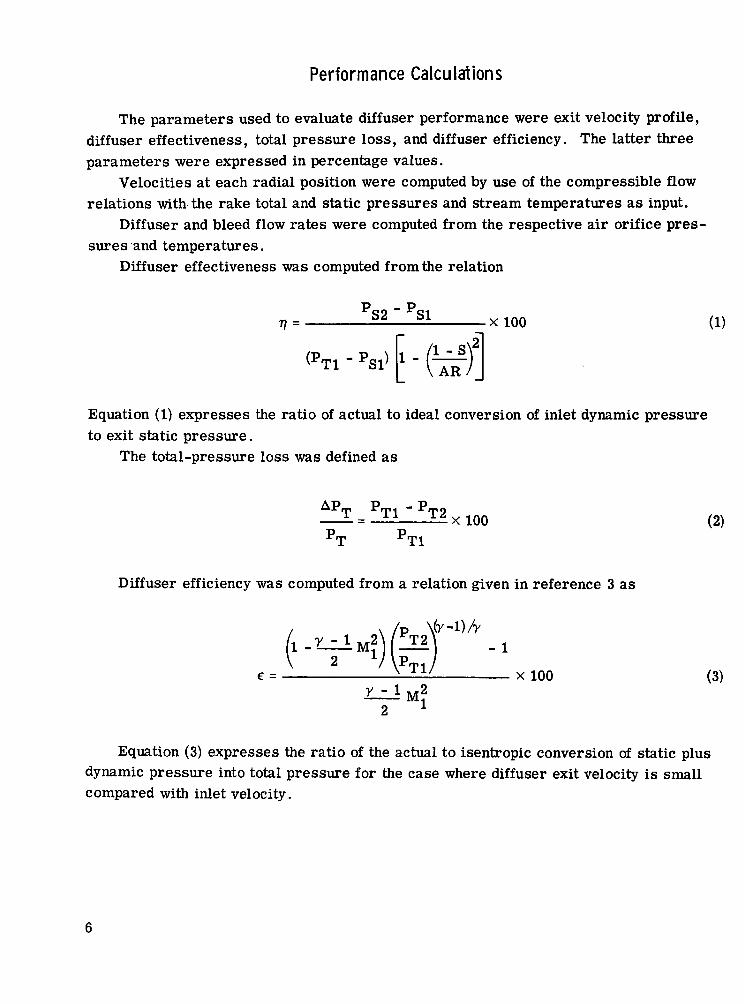
The parameters used to evaluate diffuser performance were exit velocity profile,diffuser effectiveness, total pressure loss, and diffuser efficiency. The latter threeparameters were expressed in percentage values.
Velocities at each radial position were computed by use of the compressible flowrelations with the rake total and static pressures and stream temperatures as input.
Diffuser and bleed flow rates were computed from the respective air orifice pres-sures and temperatures.
Diffuser effectiveness was computed from the relation
P - PTJ = ^ ^ X 100 (1)
(T> _ P ^^Tl SI' 1 /I - Sf|
IAR/J
Equation (1) expresses the ratio of actual to ideal conversion of inlet dynamic pressureto exit static pressure.
The total-pressure loss was defined as
- PT9^ x 100 (2)
Diffuser efficiency was computed from a relation given in reference 3 as
e = - — iii - x 100 (3)
Equation (3) expresses the ratio of the actual to isentropic conversion of static plusdynamic pressure into total pressure for the case where diffuser exit velocity is smallcompared with inlet velocity.

Test Conditions
Typical diffuser inlet conditions were:
Total pressure, N/cm (psia) 10 to 10.3 (14. 5 to 15.0)Static pressure, N/cm2 (psia) 9.3 to 9.7 (13. 5 to 14.1)Temperature, K (°F) 276 (37)Mach number 0.196 to 0.320Velocity, m/sec (ft/sec) 64.0 to 106 (211 to 347)Reynolds number (based on passage height) 2.35x10 to 3.84x10Bleed rate, percent of total flow 0 to 10
RESULTS AND DISCUSSION
The performance of the diffuser was evaluated in terms of radial velocity profiles,diffuser effectiveness, and percent total-pressure loss for each of three inlet Mach num-bers and wall suction rates ranging from 0 to 10 percent. A summary of typical per-formance data is given in table I.
Radial Velocity Profiles
The radial inlet and exit velocity profiles shown in figure 5 were obtained by plottingthe ratio of local velocity at a radial position to average velocity in the inlet and exitplanes, respectively, as a function of radial span position. The local velocity at a ra-dial position was obtained by taking the average of local velocities at three circumferen-tial positions. The resulting profiles should still be representative because the com-puted velocity spread due to circumferential nonuniformity of the flow was about ±2 per-cent for the inlet profiles and ±20 percent for the exit profiles.
Moreover, the velocity profiles were similar for the three inlet velocity test condi-tions. Therefore, only the profiles for the 0.26 nominal inlet Mach number are shownin figure 5.
Figure 5(a) shows inlet and exit profiles for the case of no suction. The inlet velocityprofile has a shape that is characteristic of annular passages. Such annular passage pro-files are treated in references 4 and 5. Although no velocities were measured in the in-ner and outer wall boundary layers, the boundary-layer profiles were faired in using theresults of references 4 and 5, as shown by the dashed portions of the inlet profile. Thehigher velocity gradients near the inner annular surface are caused by the higher shear

stresses in that region. Because the inlet profile shape is determined largely by thegeometry of the inlet annular passage, it remains the same for the various combinationsof suction (figs. 5(b) to (i)).
The exit velocity profile shape, however, is strongly influenced by wall suction.Thus, in figure 5(a) it is highly hub peaked; that is, it is attached to the inner wall butseparated from the outer wall. This is expected because of the asymmetric diffuserexit passage. The peak velocity value is 2.15 times average velocity. In figure 5(b),with 2 percent suction on the outer wall, the profile peak begins to shift towards the cen-ter of the annular passage. At 2.8 percent outer wall suction (fig. 5(c)), the flow startsto separate from the inner wall with the profile peak displaced to the 60 percent of spanposition. A further increase of suction (figs. 5(d) and (e)) will actually result in tippeaked profiles. Figure 5(f) shows the profile obtained with approximately 1.8 percentinner and 3.6 percent outer wall suction. The profile shape now is fairly symmetricwith the peak at the 50 percent span position. Some flattening has also occurred, withthe peak velocity at 1.67 times average. However, the flow is not quite attached to theouter wall since the velocity is zero at the 90 percent of span position. A similar pro-file is obtained at the suction rates shown in figure 5(g). Not until the outer wall suc-tion is increased to 5.5 percent with the inner wall suction at 3.4 percent (fig. 5(h)) isthe exit passage completely filled. The profile is now quite symmetric, and the peakvelocity is only about 1. 5 times average. Further increase of inner and outer wall suc-tion rates (fig. 5(i)) will normally cause only slight improvement in profile symmetry.For the case illustrated in figure 5(i), a slight excess of outer wall suction actuallycaused the profile peak to shift to the 60 percent of span position.
In summary the data presented in figure 5 show that the diffuser exit velocity pro-file shape is quite sensitive to varying amounts of inner and outer wall suction rates.Hence the proposed suction scheme should make it possible to shape combustor inletflow distribution in gas turbine engine applications. The ratio of outer to inner wallsuction rate to obtain a symmetric diffuser exit velocity profile depends on the geometryof the diffuser exit passage. For the geometry used herein this ratio was about 1.65.
Diffuser Effectiveness
The effect of suction on diffuser effectiveness, as defined in equation (1), is shownin figure 6 for the three inlet Mach number conditions of this test program. The opensymbols designate data obtained with suction on the outer wall only, and the solid sym-bols indicate suction on both walls. It is interesting to note that the data for all threeMach numbers fall on two distinct curves. The upper curve correlates data for outerwall suction between zero and about 2.8 percent and also the data for suction on both
8

walls. Data for outer wall suction in excess of 2.8 percent fall on the lower curve.To explain these data trends, consider the case of suction on the outer wall alone.
With no outer wall suction, the flow is completely separated from the outer wall result-ing in a diffuser effectiveness of only 37 percent. Applying suction to the outer wallcauses separation to be delayed as evidenced by a rise in diffuser effectiveness. At about2.8 percent outer wall suction, the flow is still not completely attached to the outer wall,but, due to the influence of outer wall suction, the flow now starts to separate from theinner wall. This incipient inner wall separation, also apparent from the shape of the exitvelocity profile (fig. 5(c)), causes the diffuser effectiveness to decrease abruptly fromabout 52 to 45 percent. This discontinuity is shown by the dashed line. Increasing thesuction rate on the outer wall will raise the effectiveness as shown by the lower curve.However, at about 5. 5 percent outer wall suction, the flow becomes completely attachedto the outer wall and further increase in outer wall suction rate will not raise the effec-tiveness above the plateau of 52. 5 percent.
The only way to increase diffuser effectiveness at this point is to eliminate the sepa-ration on the inner wall by applying suction to the inner wall also. As shown by the solidsymbols on the upper curve, the effectiveness could now be increased to about 68 percentat a total suction rate of 10 percent. No data were taken at suction rates in excess of10 percent because of facility limitations and also because such high bleed rates wouldlikely be unrealistic in gas turbine applications except for turbine cooling applications.However, the positive slope of the upper curve in figure 6 suggests that further improve-ment in diffuser effectiveness would be obtained by increasing the total suction rate be-yond 10 percent.
Diffuser Total Pressure Loss
The decrease of diffuser total pressure loss with suction rate is shown in figure 7for the three test Mach numbers. The data trends are in complete agreement with theexplanation of flow behavior based on diffuser effectiveness data (given in the precedingsection).
Thus, the discontinuity occurring in each of the three Mach number curves at about2.8 percent outer wall suction (dashed lines in fig. 6) is caused by the flow separationfrom the inner wall. This separation results in a sudden increase in pressure loss asshown by the upper portion of each Mach number curve. Increasing suction on the outerwall will not reduce the pressure loss significantly. With suction on both walls, how-ever, appreciable reduction in total pressure loss can be achieved as shown by the lowerportion of each Mach number curve. Compared with values obtained without suction thepressure loss could be reduced by approximately one-third at a total suction rate of10 percent.
9

It should be pointed out that the decrease of diffuser total pressure loss with in-creasing suction rate is due to both a reduction of diffuser mass flow rate as well as areduction of wall resistance. Each of the two effects contributes about one-half of theoverall reduction in total pressure loss. This can be verified by considering the topcurve of figure 7. With no suction the total pressure loss is 3.24 percent. At a10-percent suction rate the value of total pressure loss due to the decrease in diffusermass flow rate alone would be (1.0-0.1) x 3. 24 or 2.63 percent. Thus, the reductionin pressure loss due to decrease of diffuser flow rate is about 0.6 percent. The valueof pressure loss determined experimentally at a suction rate of 10 percent is about 2.02percent. This value, which includes the effect of decreased wall resistance, representsan additional 0.6 percent decrease from the 2.63 percent figure determined previously.
Diffuser Efficiency
Values of diffuser efficiency, as computed from equation (3), are shown in table I.Except for conditions where the exit velocity profile and, consequently, the total-pressure profile are highly peaked, these values are within about 5 percent of diffusereffectiveness values. The diffuser efficiency error at highly peaked exit total pressureprofile conditions is caused by the fact that the computed average exit total pressure washigher than the true value. No such error exists in diffuser effectiveness (eq. (1)),based on average static pressures, because the static-pressure profile was nearly flatat all test conditions. Hence, for this investigation, diffuser effectiveness was con-sidered to be a more reliable criterion of performance than diffuser efficiency.
APPLICABILITY OF RESULTS TO COMBUSTOR DESIGN
The purpose of this investigation was to test the feasibility of using suction to con-trol the exit velocity profile of an asymmetric annular diffuser. This feasibility was de-monstrated by the data trends discussed in the preceding sections. Thus the asymmetricbleed diffuser-combustor concept, discussed here previously and also in reference 2has been brought one step closer to practicality.
Several questions remain to be answered, however, since the absolute values of theresults obtained in this work apply only to the particular geometry tested. For example,it may be possible to increase the value of outer wall suction at which the flow separatesfrom the inner wall by changing the asymmetry of the diffuser. Furthermore, the effectof combustor blockage on diffuser exit (combustor inlet) velocity profile needs to be in-vestigated. Finally, the asymmetric bleed diffuser concept has to be tested in full-scale
10

advanced combustor rigs. Of particular interest would be a combustor using pressureatomizing fuel nozzles (ref. 6) and a swirl can combustor of the type reported in refer-ence 7. Combustors using pressure atomizing fuel nozzles should be ideally suited forthe asymmetric diffuser bleed concept since bypassing a large portion of the air aroundthe primary zone during idle or relight conditions will not impede fuel atomization. Inswirl can combustors, however, the airflow distribution has to be tailored more closely,so that the air velocity in the primary zone is high enough for good fuel atomization.
SUMMARY OF RESULTS
Velocity profile control experiments were conducted on a short asymmetric annulardiffuser provided with contour wall bleed (suction) capability. The results were asfollows:
1. Without the use of suction the exit velocity profile was highly hub peaked and com-pletely separated from the outer wall.
2. The exit velocity profile could be caused to become center peaked with about2.8 percent suction and even tip peaked with about 5 percent suction on the outer wall.
3. With suction applied to both walls (3.4 percent on inner wall and 5.6 percent onouter wall) the exit velocity profile was symmetric about the annular centerline and con-siderably flattened.
4. The shape of the exit velocity profiles with and without suction was not affectedby inlet Mach number in the range of 0.19 to 0.32.
5. Inlet velocity profile was not affected by suction or inlet Mach number in therange of 0.19 to 0.32.
6. Diffuser effectiveness (ratio of actual to ideal pressure recovery) could be in-creased from 37 percent with no suction to 67 percent with 3.7 percent inner wall and6.3 percent outer wall suction.
7. With suction applied to the outer wall only, a sudden drop in effectiveness oc-curred at a suction rate of 2.8 percent because of flow separation from the inner wall.
8. The maximum effectiveness with outer wall suction only was about 52.5 percentat a suction rate of approximately 6 percent.
9. The diffuser total pressure loss at an inlet Mach number of 0.32 could be reducedfrom 3.24 percent of inlet total pressure with no suction to about 2.05 percent with3.4 percent inner wall and 5.3 percent outer wall suction.
11

10. Similar reductions in total pressure loss could be achieved at the 0.195- and0.265-inlet Mach number test conditions.
Lewis Research Center,National Aeronautics and Space Administration,
Cleveland, Ohio, October 30, 1972,501-24.
REFERENCES
1. Sovran, Gino; and Klomp, Edward D.: Experimentally Determined Optimum Geo-metries for Rectilinear Diffusers with Rectangular, Conical or Annular Cross-Section. FLUID MECHANICS OF INTERNAL FLOW. Gino Sovran, ed., ElsevierPubl. Co., 1967, pp. 270-319.
2. Juhasz, Albert J.; and Holdeman, James D.: Preliminary Investigation of DiffuserWall Bleed to Control Combustor Inlet Airflow Distribution. NASA TN D-6435, 1971.
3. Shapiro, Ascher H.: The Dynamics and Thermodynamics of Compressible Fluid Flow.Ronald Press Co., 1953, pp. 151-152.
4. Bird, R. Byron; Stewart, Warren E.; and Lightfoot, Edwin N.: Transport Phe-nomena. John Wiley & Sons, Inc., 1960, pp. 51-56, 176-177.
5. Brighton, J. A.; and Jones, J. B.: Fully Developed Turbulent Flow in Annuli.J. Basic Eng., vol. 86, no. 4, Dec. 1964, pp. 835-844.
6. Wear, Jerrold D.; Perkins, Porter J.; and Schultz, Donald F.: Tests of a Full-Scale Annular Ram-Induction Combustor for a Mach 3 Cruise Turbojet Engine.NASA TND-6041, 1970.
7. Niedzwiecki, Richard W.; Juhasz, Albert J.; and Anderson, David N.: Performanceof a Swirl-Can Primary Combustor to Outlet Temperatures of 3600° F (2256 K).NASA TM X-52902, 1970.
12

TABLE I. - DIFFUSER PERFORMANCE DATA
Read-ing
123
45
6789
10
1112
131415
16
171819202122
23242526
27282930
31
DiffuserinletMach
number,M
0.264.267.266.265.265.266.267.270.268.268
.316
.316
.318
.320
.317
.317
.316
.316
.317
.319
.319
.321
.196
.197
1
1.198.194.197.198
Airflow rate
kg/sec
3.283.303.293.283.273.293.283.32.3.293.28
3.933.913,923.933.913.913.903.913.923.903.903.91
2.482.472.48
1
f
2.422.472.47
Ib/sec
7.247.287.257.237.227.267.237.317.257.24
8.678.628.648.668.638.638.618.618.648.608.598.63
5.465.455.465.465.475.475.345.445.45
Inlet totaltemperature
K
277
275
1
276
°F
38
'
35
3636
36
i
36
373737
Suction rate, percent
Innerwall
0
'
1.842.673.423.71
0
i
2.263.023.43
0
2.382.233.19
Outerwall
02.022.833.604.466.283.594.365.566.34
01.392.072.843.133.783.834.735.363.754.775.26
02.652.984.305.827.284.455.715.76
Total
02.022.833.604.466.285.437.028.98
10.04
01.392.072.843.133.783.834.735.366.007.808.69
02.652.984.305.827.286.837.948.95
Totalpressure
loss,AP/p,percent
2.39 .2.092.502.392.362.402.201.831.621.67
3.242.942.762.703.022.982.933.012.972.292.182.05
1.281.051.171.161.191.21
.92
1.01.93
Diffuser
Effective-ness,
percent
37.147.645.047.949.050.957.058.365.567.2
38.145.649.552.046.349.549.450.150.860.663.767.1
38.152.246.851.152.552.759.157.365.5
Effi-ciency,percent
53.059.251.753.353.753.355.863.467.967.1
54.459.362.163.457.758.758.857.958.269.270.471.6
53.963.558.059.158.557.264.861.865.4
Exitprofilepeak
position,percentof span
30306060
60705060
50 to 6060
30
' 1
5060
1 '30 to 40
4040
30
3060
i
50
Exitprofilepeak
value ,V /Vm' av
2.152.101.942.081.981.961.671.611.531.55
2.112.062,062.001.932.062.052.072.041.611.591.63
2.101.911.841.991.991.921.691.761.68
13

,-~Suction flow line(inner wall)
Figure 1. - Flow system.
14

Air flowi
Mixing chamber-^
/-Outer wall suction manifold
Three exit pitot-staticrakes (translate and
J rotate) tilted fromplane of figure
Diam, 28(11)
L Displaced exit .inner surface 1
n - 1 - —a <- Lucite housingLRemoveable walls
\To ejector 1
Diam- 48J(19) to eiector
Mounting flange
Figure 2. - Cross section of asymmetric annular diffuser test apparatus. (Dimensions are in cm (in.1).)
15

•Outer wall
Bleed flow • Suctionchamber
Wall staticpressure ports-j
Diam, 40.6(16)—
Main flow ••
Diam, 35.6(14)—
oooop
Outer passage
ooCf' pilot
probeO positions
O 3H
O
- D i a m , 48.3(19)
Inner passage /-.0501.020)suction slots O
/-Centerlineof/ inlet passage
-Diam, 38.1(15)
^Displaced exitinner surface
-Diam, 33(13)
Diam, 28(11)
Figure 3. - Diffuser contour wall detail; inlet passage height, H, 2.54 cm (1.0 in.). (Dimensionsare in cm (in.).)
C-72-1495
Figure 4. - Asymmetric annular diffuser (oblique view looking upstream).
16

Q> C Xl/> — LU
•I D O
L
TI \
oCM'
c.o>o
&CM
cf.o*-•o3in
vOCM
cu
"I3C
fe 5I s
7
1\
_O•*-*CO
~-.io
oCM
vO
00
o
I/I3O
ina>
eo.
C —^3 (̂
'"5 '̂3 L.
^D iC
Q
irCo>k_3
S vO
ueds
O O
17

OJ
v^eQ. *f*
tin —
«*_.t: a
ea>
.2"o
1
3_c
I
7
\\
CM T_OO)
ca>
ooCM'
co
oo
\ O"o
OOO
OCM
ueds
18

1
eQ.
CDon3
3=
\
\
c:CD
§ 8
>to
O —
-aO>
1-̂ -«o
5£CD
ooCM
C.2
19
J

NATIONAL AERONAUTICS AND SPACE ADMINISTRATIONWASHINGTON. D.C. 2OS46
OFFICIAL. BUSINESSPENALTY FOR PRIVATE u»E »3<» SPECIAL FOURTH-CLASS RATE
BOOK
POSTAGE AND FEES PAIDNATiONAU AERONAUTICS Aftl
SPACE ADMINISTRATION
POSTMASTER: If Undellverabl* CS«c«on 158Postal M&miatlf Bo Hot Retwro
"The aeronautical' and space activities of the United States shall beconducted so as to contribute ...'.to the expansion of human knowl-edge of phenomena in the atmosphere and space, the Administrationshall provide for the widest practicable and appropriate disseminationof information concerning its activities and the results thereof"
—NATIONAL AratoNAimcs AND SPACE Acr OF 1958
NASA SCIENTIFIC AND TECHNICAL PUBLICATIONSTECHNICAL REPORTS: Scientific andtechnical information considered important,complete, and a lasting contribution to existingknowledge.
TECHNICAL NOTES: Information less broadin scope but nevertheless of importance as acontribution to existing knowledge.
TECHNICAL MEMORANDUMS:Information receiving limited distributionbecause of preliminary data, security classifica-tion, or other reasons. Also includes conferenceproceedings with either limited or unlimiteddistribution.
CONTRACTOR REPORTS: Scientific andtechnical information generated under a NASAcontract or grant and considered an importantcontribution to existing knowledge.
TECHNICAL TRANSLATIONS: Informationpublished in a foreign language consideredto merit NASA distribution in English.
SPECIAL PUBLICATIONS: Informationderived from or of value to NASA activities.Publications include final reports of majorprojects, monographs, data compilations,handbooks, sourcebooks, and specialbibliographies.
TECHNOLOGY irniJZATIONPUBLICATIONS: Information on technologyused by NASA that may be of particularinterest in commercial and other non-aerospaceapplications. Publications include Tech Briefs,Technology Utilization Reports andTechnology Surveys.
Details on the availability of these publications may be obfained from:
SCIENTIFIC AND TECHNICAL INFORMATION OFFICE
N A T I O N A LWashington, D.C. 20546