contributions to securing mobile ad hoc networks against
TRANSCRIPT

University of Wollongong University of Wollongong
Research Online Research Online
University of Wollongong Thesis Collection 1954-2016 University of Wollongong Thesis Collections
2016
Contributions to securing mobile ad hoc networks against wormhole Contributions to securing mobile ad hoc networks against wormhole
attacks in multirate transmission attacks in multirate transmission
Shams-Ud-Din Qazi University of Wollongong
Follow this and additional works at: https://ro.uow.edu.au/theses
University of Wollongong University of Wollongong
Copyright Warning Copyright Warning
You may print or download ONE copy of this document for the purpose of your own research or study. The University
does not authorise you to copy, communicate or otherwise make available electronically to any other person any
copyright material contained on this site.
You are reminded of the following: This work is copyright. Apart from any use permitted under the Copyright Act
1968, no part of this work may be reproduced by any process, nor may any other exclusive right be exercised,
without the permission of the author. Copyright owners are entitled to take legal action against persons who infringe
their copyright. A reproduction of material that is protected by copyright may be a copyright infringement. A court
may impose penalties and award damages in relation to offences and infringements relating to copyright material.
Higher penalties may apply, and higher damages may be awarded, for offences and infringements involving the
conversion of material into digital or electronic form.
Unless otherwise indicated, the views expressed in this thesis are those of the author and do not necessarily Unless otherwise indicated, the views expressed in this thesis are those of the author and do not necessarily
represent the views of the University of Wollongong. represent the views of the University of Wollongong.
Recommended Citation Recommended Citation Qazi, Shams-Ud-Din, Contributions to securing mobile ad hoc networks against wormhole attacks in multirate transmission, Doctor of Philosophy thesis, School of Computer Science and Software Engineering, University of Wollongong, 2016. https://ro.uow.edu.au/theses/4787
Research Online is the open access institutional repository for the University of Wollongong. For further information contact the UOW Library: [email protected]

Contributions to Securing Mobile Ad HocNetworks against Wormhole Attacks in Multirate
Transmission
Shams-Ud-Din Qazi
Supervisor:Prof Yi Mu
Co-supervisors:Dr. Raad Raad
Prof Willy Susilo
This thesis is presented as part of the requirements for the conferral of the degree:
Doctor of Philosophy
The University of WollongongSchool of Computer Science and Software Engineering
September 19, 2016

Declaration
I, Shams-Ud-Din Qazi, declare that this thesis submitted in partial fulfilment of the
requirements for the conferral of the degree Doctor of Philosophy, from the University
of Wollongong, is wholly my own work unless otherwise referenced or acknowledged.
This document has not been submitted for qualifications at any other academic in-
stitution.
Shams-Ud-Din Qazi
September 19, 2016

Abstract
The last two decades have seen phenomenal growth in the use of wireless devices. A
class of these devices that operates in an Ad hoc manner is capable of self-organising
and self-configuration without the help of any predefined network infrastructure and
are able to extend their communication range with the help of their neighbours.
These types of networks are commonly referred to as Mobile Ad hoc Networks or
MANETs for short.
Given the distributed nature of a MANET and the need to share routing and
other information, securing a MANET against intrusion is a challenging task. Secu-
rity of MANETs is an active research area with many threats like jamming, eaves-
dropping, rushing, packet dropping, data corruption and session hijacking etc.
Routing, or the act of discovering and forwarding packets between nodes is criti-
cal in MANETs. Securing routing protocols is very important as this is a weak point
where intruders can target the wireless devices that form the MANET. Adversaries
or hackers have many reasons and means by which to target MANET devices. One of
which is to disrupt communication in MANETs, the other is to reroute information
through other devices for copying/modifying/listening to data traffic.
This thesis addresses the security threat of a wormhole attack. A wormhole
attack takes place when a malicious device is able to join a MANET and insert
itself into the address of legitimate devices and be seen as the shortest path to other
legitimate devices in the network. Hence, the next effect being that this malicious
device is always chosen to route information to these devices. Once this is achieved,
the malicious device could listen/modify/copy or simply disrupt normal routing
operations in the network.
This thesis proposes three solutions that rely on Round Trip Time and statistical
analysis to detect and flag malicious nodes that attempt a wormhole attack. The
work presented is significant, as the current state of the art does not take into account
the variable bit rate nature of the wireless channel and assumes a constant bit rate
leading to many algorithms to either fail or perform sub optimally. More specifically
the first contribution of the thesis looks at securing the Dynamic Source Routing
(DSR) protocol. A further contribution is made where we combine the round trip
time with a sentinel mechanism where devices that make up the MANET, monitor
each others activity to ensure against wormhole attacks. In this case we apply this to
another routing protocol known as Ad Hoc On Demand Distance Vector (AODV).
This thesis shows that a highly cited security protocol known as DelPHI is unable to
iii

iv
secure Ad Hoc On Demand Distance Vector (AODV) in a multi-rate transmission
environment (such as IEEE 802.11g/n) and proposes an extension to DelPHI (M-
DelPHI) that adapts it to the multirate 802.11 wireless channel. M-DelPHI performs
exceptionally well, resulting in above 90% wormhole detection rate against in-band
and out-of-band wormholes under the specified test conditions.
The final part of the thesis uses the CUSUM method to detect any sudden
changes from the long term norm of the routing information, hence providing another
indicator of a wormhole attack. The work proposes an Multirate Intrusion Detection
System (MIDS) to detect intrusion of adversaries in order to detect wormhole attacks
(In-band and out-of-band). The proposed Multirate Intrusion Detection System
(MIDS) secures the AODV routing protocol in multirate transmission and simulation
results show that the detection rate is extremely high.
Hence, the main themes of this thesis are wormhole attacks, MANETs and
Multirate. While the constant bit rate assumption made by potentially all studies
related to MANET seems to be insignificant, it is very clear from this work that
most detection methods that rely on a timing mechanism will easily break and
produce erroneous results. Hence, this thesis highlights the fact that making the
wireless channel constant for MANET is not a realistic assumption and further most
solutions will perform very poorly when simulated under realistic wireless multirate
conditions.

Acknowledgements
First of all, I would like to thanks my supervisors Dr Raad Raad, Prof Yi Mu and
Prof Willy Susilo, for their advices, encouragement and constructive criticism during
my Phd studies. I must evidence their wealth of knowledge in the field of wireless
networks, security and cryptography. I also appreciate their efforts in guiding me in
the field of network security, especially in the area of wireless network security.
I would like to thank University of Wollongong for providing me the opportunity
and financial support to carry out my PhD studies. I would also like to thank all of
my research group members especially Ibrahim Elashry, Nan Li, Fuchun Guo and
Zhenfei Zhang for their help during my studies. I would also like to thank all staff
members of Centre for Computer and Information Security Research and the School
of Computer Science and Software Engineering for their support.
Finally, I would like to thanks my parents and my family, for their relentless
support throughout my entire life with their love and guidance. Without them, I
would never be able to have all my achievements.
v

Publications
1. Shams Qazi, Raad Raad, Yi Mu and Willy Susilo. Securing DSR against
wormhole attacks in multirate ad hoc networks. Elsevier Journal of Network
and Computer Applications (JNCA), Year: 2013, Vol: 36(2), Pages: 582-592.
2. Shams Qazi, Raad Raad, Yi Mu and Willy Susilo. Multirate DelPHI to secure
Multirate Ad Hoc Networks against Wormhole attacks. Submitted to Elsevier
Journal of Computer Communications, Year: 2015.
3. Shams Qazi, Raad Raad, Yi Mu and Willy Susilo. Multirate Intrusion Detec-
tion System to Secure Multirate Ad Hoc Networks against Wormhole attacks.
Submitted to Elsevier Network and Computer Applications - JNCA, Year:
2015.
vi

[This page is intentionally left blank]

Contents
Abstract iii
Acknowledgements v
Publications vi
1 Introduction 1
1.1 Background . . . . . . . . . . . . . . . . . . . . . . . . . . . . . . . . 1
1.2 Problem Description . . . . . . . . . . . . . . . . . . . . . . . . . . . 6
1.3 Our Contribution . . . . . . . . . . . . . . . . . . . . . . . . . . . . . 7
1.3.1 Major Contributions . . . . . . . . . . . . . . . . . . . . . . . 7
1.4 Thesis Structure . . . . . . . . . . . . . . . . . . . . . . . . . . . . . . 8
2 Background 12
2.1 Introduction . . . . . . . . . . . . . . . . . . . . . . . . . . . . . . . . 12
2.2 Mobile Ad hoc Networks . . . . . . . . . . . . . . . . . . . . . . . . . 13
2.2.1 Types of MANETs . . . . . . . . . . . . . . . . . . . . . . . . 13
2.2.2 Characteristics of MANETs . . . . . . . . . . . . . . . . . . . 17
2.2.3 Applications of MANETs . . . . . . . . . . . . . . . . . . . . 18
2.3 Routing Protocols . . . . . . . . . . . . . . . . . . . . . . . . . . . . . 18
2.3.1 OLSR . . . . . . . . . . . . . . . . . . . . . . . . . . . . . . . 21
2.3.2 WRP . . . . . . . . . . . . . . . . . . . . . . . . . . . . . . . . 22
2.3.3 AODV . . . . . . . . . . . . . . . . . . . . . . . . . . . . . . . 22
2.3.4 DSR . . . . . . . . . . . . . . . . . . . . . . . . . . . . . . . . 22
2.3.5 Zone Routing Protocol (ZRP) . . . . . . . . . . . . . . . . . . 23
2.4 MANET based on IEEE 802.11 . . . . . . . . . . . . . . . . . . . . . 23
2.4.1 IEEE 802.11b . . . . . . . . . . . . . . . . . . . . . . . . . . . 24
2.4.2 IEEE 802.11g . . . . . . . . . . . . . . . . . . . . . . . . . . . 24
2.4.3 IEEE 802.11a . . . . . . . . . . . . . . . . . . . . . . . . . . . 24
2.4.4 IEEE 802.11n . . . . . . . . . . . . . . . . . . . . . . . . . . . 25
2.4.5 Multirate Transmission in IEEE 802.11 . . . . . . . . . . . . . 25
2.5 Security Requirements . . . . . . . . . . . . . . . . . . . . . . . . . . 27
2.5.1 General Security Requirements . . . . . . . . . . . . . . . . . 29
2.5.2 General Security Threats . . . . . . . . . . . . . . . . . . . . . 29
2.5.3 Security Threats in MANETs . . . . . . . . . . . . . . . . . . 32
viii

CONTENTS ix
2.5.4 Security Threats against Routing in MANETs . . . . . . . . . 34
2.6 Wormhole Attacks . . . . . . . . . . . . . . . . . . . . . . . . . . . . 35
2.6.1 Modes of Wormhole attacks . . . . . . . . . . . . . . . . . . . 35
2.7 Summary . . . . . . . . . . . . . . . . . . . . . . . . . . . . . . . . . 38
3 Literature Review 40
3.1 Introduction . . . . . . . . . . . . . . . . . . . . . . . . . . . . . . . . 40
3.2 Hardware/Software based solutions . . . . . . . . . . . . . . . . . . . 41
3.3 Statistical/Graph Analysis based solutions . . . . . . . . . . . . . . . 45
3.3.1 Sequential Probability Ration Test (SPRT) . . . . . . . . . . . 45
3.3.2 Non-parametric Change Detection (CUSUM) . . . . . . . . . 46
3.4 Challenge/Response based solutions . . . . . . . . . . . . . . . . . . . 50
3.5 Round Trip Time (RTT) based solutions . . . . . . . . . . . . . . . . 56
3.6 IDS based solutions . . . . . . . . . . . . . . . . . . . . . . . . . . . . 61
3.7 Comparisons of Existing Solutions . . . . . . . . . . . . . . . . . . . . 65
3.8 Summary . . . . . . . . . . . . . . . . . . . . . . . . . . . . . . . . . 70
4 Multirate DSR 71
4.1 Introduction . . . . . . . . . . . . . . . . . . . . . . . . . . . . . . . . 71
4.2 Background . . . . . . . . . . . . . . . . . . . . . . . . . . . . . . . . 72
4.2.1 DSR . . . . . . . . . . . . . . . . . . . . . . . . . . . . . . . . 72
4.2.2 TTM . . . . . . . . . . . . . . . . . . . . . . . . . . . . . . . . 74
4.3 Proposed Protocol . . . . . . . . . . . . . . . . . . . . . . . . . . . . 76
4.3.1 Notations . . . . . . . . . . . . . . . . . . . . . . . . . . . . . 76
4.3.2 System Assumptions and Definitions . . . . . . . . . . . . . . 77
4.3.3 Protocol Run . . . . . . . . . . . . . . . . . . . . . . . . . . . 79
4.3.4 Attack Model . . . . . . . . . . . . . . . . . . . . . . . . . . . 84
4.4 Security Analysis . . . . . . . . . . . . . . . . . . . . . . . . . . . . . 89
4.4.1 Security Against packet encapsulation wormholes . . . . . . . 90
4.4.2 Security against out-of-band wormholes . . . . . . . . . . . . . 90
4.4.3 Security against Packet Relay wormholes . . . . . . . . . . . . 91
4.4.4 Security against TTM [THL+07] threats . . . . . . . . . . . . 91
4.5 Performance Analysis . . . . . . . . . . . . . . . . . . . . . . . . . . . 92
4.5.1 Simulation Scenario . . . . . . . . . . . . . . . . . . . . . . . . 92
4.5.2 Results and Discussions . . . . . . . . . . . . . . . . . . . . . 93
4.6 Summary . . . . . . . . . . . . . . . . . . . . . . . . . . . . . . . . . 95
5 Multirate DelPHI 97
5.1 Introduction . . . . . . . . . . . . . . . . . . . . . . . . . . . . . . . . 97
5.2 Background . . . . . . . . . . . . . . . . . . . . . . . . . . . . . . . . 98

CONTENTS x
5.2.1 AODV . . . . . . . . . . . . . . . . . . . . . . . . . . . . . . . 98
5.2.2 DelPHI . . . . . . . . . . . . . . . . . . . . . . . . . . . . . . 100
5.2.3 DelPHI in a Multirate Environment . . . . . . . . . . . . . . . 101
5.3 Proposed Protocol . . . . . . . . . . . . . . . . . . . . . . . . . . . . 104
5.3.1 Proposed Run . . . . . . . . . . . . . . . . . . . . . . . . . . . 105
5.3.2 Attack Model . . . . . . . . . . . . . . . . . . . . . . . . . . . 109
5.4 M-DelPHI Performance Analysis . . . . . . . . . . . . . . . . . . . . . 110
5.4.1 Simulation Environment . . . . . . . . . . . . . . . . . . . . . 111
5.4.2 Potential Failure Mode Analysis . . . . . . . . . . . . . . . . . 116
5.4.3 Computation, Memory and Transmission Overhead . . . . . . 118
5.5 Summary . . . . . . . . . . . . . . . . . . . . . . . . . . . . . . . . . 120
6 Multirate IDS 121
6.1 Introduction . . . . . . . . . . . . . . . . . . . . . . . . . . . . . . . . 121
6.2 Background . . . . . . . . . . . . . . . . . . . . . . . . . . . . . . . . 121
6.3 Proposed Intrusion Detection System - MIDS . . . . . . . . . . . . . 122
6.3.1 Notations . . . . . . . . . . . . . . . . . . . . . . . . . . . . . 124
6.3.2 Systems assumptions and Definitions . . . . . . . . . . . . . . 124
6.3.3 Architecture of MIDS . . . . . . . . . . . . . . . . . . . . . . . 126
6.3.4 Algorithms in MIDS . . . . . . . . . . . . . . . . . . . . . . . 128
6.3.5 Working Steps of MIDS . . . . . . . . . . . . . . . . . . . . . 131
6.4 MIDS Performance Analysis . . . . . . . . . . . . . . . . . . . . . . . 132
6.4.1 Simulation Environment . . . . . . . . . . . . . . . . . . . . . 132
6.4.2 Computation and Memory Overhead . . . . . . . . . . . . . . 135
6.5 Summary . . . . . . . . . . . . . . . . . . . . . . . . . . . . . . . . . 135
7 Conclusion 137
A Glossary 139
Bibliography 141

List of Tables
1.1 Attacks on each layer in MANETs . . . . . . . . . . . . . . . . . . . . 3
2.1 IEEE 802.11 standards comparison [SGTL11] . . . . . . . . . . . . . 25
2.2 Simulation Parameters for Multirate IEEE 802.11b [AHR04] . . . . . 26
2.3 IEEE 802.11b Transmission Ranges [AHR04] . . . . . . . . . . . . . . 27
2.4 Simulation Inputs . . . . . . . . . . . . . . . . . . . . . . . . . . . . . 28
4.1 Notations . . . . . . . . . . . . . . . . . . . . . . . . . . . . . . . . . 77
4.2 IEEE 802.11g Data rates based on Distance . . . . . . . . . . . . . . 78
4.3 RTT between participating nodes and destination . . . . . . . . . . . 82
4.4 RTT between intermediate nodes . . . . . . . . . . . . . . . . . . . . 82
4.5 Processing Time Calculations . . . . . . . . . . . . . . . . . . . . . . 83
4.6 RTTs with destination in TTM . . . . . . . . . . . . . . . . . . . . . 85
4.7 RTTs between intermediate nodes in TTM . . . . . . . . . . . . . . . 86
4.8 RTT between participating nodes and destination . . . . . . . . . . . 86
4.9 RTT between intermediate nodes . . . . . . . . . . . . . . . . . . . . 87
4.10 Processing times at intermediate nodes . . . . . . . . . . . . . . . . . 87
4.11 Expected and Actual RTTs . . . . . . . . . . . . . . . . . . . . . . . 87
4.12 RTT between participating nodes and destination . . . . . . . . . . . 88
4.13 RTT between intermediate nodes . . . . . . . . . . . . . . . . . . . . 89
4.14 Processing times at intermediate nodes . . . . . . . . . . . . . . . . . 89
4.15 Expected and Actual RTTs . . . . . . . . . . . . . . . . . . . . . . . 89
4.16 Simulation Inputs . . . . . . . . . . . . . . . . . . . . . . . . . . . . . 93
5.1 RTTs and DPH calculation in DelPHI Protocol . . . . . . . . . . . . 102
5.2 RTTs and DPH calculation in DelPHI Protocol . . . . . . . . . . . . 104
5.3 Notations . . . . . . . . . . . . . . . . . . . . . . . . . . . . . . . . . 105
5.4 Round Trip Time (RTT) between participants and destination . . . . 107
5.5 RTT between intermediate nodes . . . . . . . . . . . . . . . . . . . . 108
5.6 Processing Time . . . . . . . . . . . . . . . . . . . . . . . . . . . . . . 108
5.7 RTT between participating nodes and destination . . . . . . . . . . . 110
5.8 RTT between intermediate nodes . . . . . . . . . . . . . . . . . . . . 110
5.9 Processing times at intermediate nodes . . . . . . . . . . . . . . . . . 110
5.10 Expected and Actual RTTs . . . . . . . . . . . . . . . . . . . . . . . 111
5.11 Simulation Inputs . . . . . . . . . . . . . . . . . . . . . . . . . . . . . 111
xi

LIST OF TABLES xii
5.12 Simulation Inputs . . . . . . . . . . . . . . . . . . . . . . . . . . . . . 112
6.1 Notations . . . . . . . . . . . . . . . . . . . . . . . . . . . . . . . . . 124
6.2 IEEE 802.11g Data rates based on Distance . . . . . . . . . . . . . . 126
6.3 RREQ message format with additional fields . . . . . . . . . . . . . . 127
6.4 RREP message format with additional fields . . . . . . . . . . . . . . 127
6.5 Routing table entry . . . . . . . . . . . . . . . . . . . . . . . . . . . . 127
6.6 History Table at Master Node . . . . . . . . . . . . . . . . . . . . . . 128
6.7 Simulation Inputs . . . . . . . . . . . . . . . . . . . . . . . . . . . . . 132
A.1 Glossary Table . . . . . . . . . . . . . . . . . . . . . . . . . . . . . . 139

List of Figures
1.1 Thesis Structure . . . . . . . . . . . . . . . . . . . . . . . . . . . . . . 11
2.1 Structure of background chapter . . . . . . . . . . . . . . . . . . . . . 12
2.2 Wireless ad hoc network . . . . . . . . . . . . . . . . . . . . . . . . . 13
2.3 Body Area Network (BAN) [ban] . . . . . . . . . . . . . . . . . . . . 14
2.4 Personal Area Network (PAN) . . . . . . . . . . . . . . . . . . . . . . 15
2.5 Wireless Local Area Network (WLAN) . . . . . . . . . . . . . . . . . 16
2.6 Metropolitan/Wide Area Network (MAN/WAN) . . . . . . . . . . . . 16
2.7 Types of wireless ad hoc routing protocols . . . . . . . . . . . . . . . 20
2.8 OLSR Routing Mechanism [OLS03] . . . . . . . . . . . . . . . . . . . 21
2.9 IEEE 802.11b Transmission Ranges [AHR04] . . . . . . . . . . . . . . 27
2.10 RTT Calculation in Multirate Transmission . . . . . . . . . . . . . . 28
2.11 Man-in-the-middle attack [QMS08] . . . . . . . . . . . . . . . . . . . 32
2.12 Attacks on each layer in Mobile Ad hoc Networks . . . . . . . . . . . 33
2.13 Wormhole Tunnel using Encapsulation . . . . . . . . . . . . . . . . . 37
2.14 Wormhole Tunnel using Out-of-Band Channel . . . . . . . . . . . . . 37
3.1 The Structure of Literature Review . . . . . . . . . . . . . . . . . . . 41
3.2 Steps for wormhole detection in SAM [QSL07] . . . . . . . . . . . . . 49
3.3 Format of a probe packet [QSL07] . . . . . . . . . . . . . . . . . . . . 50
3.4 Processing of RREQ in WARP [Su10] . . . . . . . . . . . . . . . . . . 52
3.5 Processing of RREP in WARP [Su10] . . . . . . . . . . . . . . . . . . 52
3.6 Timing Diagram of NEVO without wormhole [SB08] . . . . . . . . . 54
3.7 RREP Packet Structure in WHOP [GKD11] . . . . . . . . . . . . . . 55
3.8 Hound Packet Structure in WHOP [GKD11] . . . . . . . . . . . . . . 55
3.9 Block Diagram of BAIDS Agent [SRMD14] . . . . . . . . . . . . . . . 63
3.10 IDS architecture representing various modules [NS07] . . . . . . . . . 65
3.11 Comparison Table 1 . . . . . . . . . . . . . . . . . . . . . . . . . . . . 67
3.12 Comparison Table 2 . . . . . . . . . . . . . . . . . . . . . . . . . . . . 68
3.13 Comparison Table 3 . . . . . . . . . . . . . . . . . . . . . . . . . . . . 69
4.1 Route Discovery in DSR Protocol . . . . . . . . . . . . . . . . . . . . 73
4.2 Time of RREQ and RREP packets . . . . . . . . . . . . . . . . . . . 75
4.3 Route Request in the absence of Wormhole Attack . . . . . . . . . . . 81
4.4 Route Request from Source S to Destination D . . . . . . . . . . . . . 85
xiii

LIST OF FIGURES xiv
4.5 Route Request under Wormhole Tunnel with Encapsulation . . . . . 88
4.6 Wormhole Tunnel using Out-of-Band Channel . . . . . . . . . . . . . 90
4.7 Wormhole Detection Rate . . . . . . . . . . . . . . . . . . . . . . . . 94
4.8 Wormhole Detection rate in different background traffic . . . . . . . . 95
4.9 Transmission overhead M-DSR and TTM . . . . . . . . . . . . . . . . 96
5.1 Route Discovery in AODV Protocol . . . . . . . . . . . . . . . . . . . 99
5.2 Route Request from S to D . . . . . . . . . . . . . . . . . . . . . . . 101
5.3 Route Request from Source to Destination . . . . . . . . . . . . . . . 103
5.4 Route Request in the absence of Wormhole Attack . . . . . . . . . . . 106
5.5 Wormhole Detection in Static Ad Hoc Network . . . . . . . . . . . . 112
5.6 Wormhole Detection in Inbound Attack . . . . . . . . . . . . . . . . . 113
5.7 Wormhole Detection in Out-of-Band Attack . . . . . . . . . . . . . . 114
5.8 Wormhole Detection rate in different background traffic . . . . . . . . 115
5.9 Wormhole Detection in M-DelPHI, DelPHI and M-DSR . . . . . . . . 116
5.10 False Positive in M-DelPHI, DelPHI and M-DSR . . . . . . . . . . . 117
5.11 Route Request from Source to Destination . . . . . . . . . . . . . . . 118
5.12 Transmission overhead of DelPHI and M-DelPHI . . . . . . . . . . . 119
6.1 In-band Wormhole Tunnel . . . . . . . . . . . . . . . . . . . . . . . . 123
6.2 Out-of-band Wormhole Tunnel . . . . . . . . . . . . . . . . . . . . . . 124
6.3 Multirate Transmission Environemnt . . . . . . . . . . . . . . . . . . 125
6.4 Architecture of MIDS . . . . . . . . . . . . . . . . . . . . . . . . . . . 128
6.5 Wormhole Detection . . . . . . . . . . . . . . . . . . . . . . . . . . . 133
6.6 Wormhole Detection against Wormhole (Inbound and out-of-band)
Attacks . . . . . . . . . . . . . . . . . . . . . . . . . . . . . . . . . . 134
6.7 Wormhole Detection rate in different background traffic . . . . . . . . 134

[This page is intentionally left blank]

Chapter 1
Introduction
1.1 Background
The advancement in communication systems especially “wireless” and the prolifera-
tion of mobile devices has tremendously increased the demand for mobile networks.
Mobile devices that operate in ad hoc manner are capable of self-organisation and
self-configuration without the help of any predefined network infrastructure. These
mobile devices are also able to extend their communication range with the help of
their neighbours. These types of networks are commonly referred to as Mobile Ad
hoc Networks or MANETs for short.
MANET is a form of wireless communication network which allows communica-
tion without any pre-defined infrastructure unlike wired networks. Mobile devices
in MANETs are commonly known as nodes and are capable of working as a com-
munication end-point as well as a router at the same time. Due to self maintenance,
self configuration and multi-hop nature, MANETs obtained tremendous attention
in current communication environment. Furthermore, these features have evolved
the MANETs into being the basis for sensor networks ([CG03], [DKB05b], [Mil07],
[SNK05], [WAR06]), peer to peer wireless networks [Cam04] and wireless mesh net-
works (WMNs) ([AWW05], [BCG05]) etc.
MANETs are most commonly used in disaster relief operations or military op-
erations where no infrastructure is available or one cannot rely on a fixed infras-
tructure. MANETs can also be used to extend the coverage area or reduce the load
of existing networks in infrastructure based communication systems. Due to mobile
nature, the nodes have some constraints which increases the number of challenges
for the implementation of MANETs. Some of these constraints are as below:
• Limited power
• Limited memory
• Multi-hop routing
• Frequency allocation
• Security and Privacy
1

CHAPTER 1. INTRODUCTION 2
Routing in mobile ad hoc networks is also an important challenge as it depends
upon the cooperation of all the nodes and their fair behaviour because of the multi-
hop nature. A routing protocol collects, updates and forwards all the information
related to finding the specific route between the source and the destination. Due to
the distinct nature and challenges involved in the implementation of MANETs, dif-
ferent types of multi-hop routing protocols are required such as ARIADNE [HPJ05],
DSR [JMB01], ARAN [SLD+05], [RT99], AODV [PBRD03], TORA [Par01], DSDV
[PVA+10a]. Generally, these protocols are classified into three major groups:
1. Table-driven routing protocols (Proactive)
2. On-demand routing protocols (Reactive)
3. Hybrid (Cluster based approach)
In table-driven routing protocols, each node maintains a routing table and up-
dates after a specific time period to keep consistent and up-to-date routing informa-
tion. The main disadvantage of this approach is that a sufficient amount of data is
required to be transferred for route maintenance. In on-demand routing protocols,
whenever there is a requirement, routes are created. In this approach, whenever a
node needs to send data to a specific destination, it generates a route request by
flooding the route request packet to find out the suitable route to the destination.
This route will remain valid until a failure of this route is detected. The main dis-
advantages of this approach are excessive flooding and high latency time in route
discovery which may lead to network clogging. In hybrid routing protocol, advan-
tages of both proactive and reactive routing protocols combined to obtain better and
efficient routes. The hybrid routing is originally established with the help of proac-
tive routing and this then serves the demand of additional nodes through reactive
flooding.
In general, an on-demand routing approach is more preferable in MANETs as
there is no need to keep routing tables and no periodical propagated messages re-
quired, so mobile devices can save their limited memory and power.
MANETs are much more exposed to different security threats as compared to
wired networks. This is due to the shared wireless physical medium, usually due
to a lack of central management, limited resources in terms of power, memory and
processing and a highly dynamic topology. Adversaries can attack any layer of the
protocol stack. Table 1.1 presents a summary of possible attacks at each layer of
protocol stack.
As discussed earlier routing in MANETs is multi-hop in nature and depends
upon fair cooperation of neighbouring nodes for the transmission of routing and

CHAPTER 1. INTRODUCTION 3
Layer AttacksApplication Layer Repudiation, Data corruptionTransport Layer Session Hijacking, SYN floodingNetwork Layer Wormhole, Blackhole, Greyhole, Rushing,
Byzantine, Flooding, Resource consumptionData Link Layer Backoff manipulation, IFS manipulation,
Data dropping, RTS/CTS Spurious attacksPhysical Layer Jamming, Interceptions, Eavesdropping
Table 1.1: Attacks on each layer in MANETs
data packets between the participating nodes. This makes routing in MANETs more
vulnerable to different types of attacks, because of the shared wireless medium. It
is quite obvious for intruders to join the network and start listening or participating
in the network traffic. Once they become part of the network then they can eas-
ily disrupt communication throughout the network by launching different types of
attacks as mentioned in Table 1.1.
Adversaries have many reasons and means by which they can easily target
MANET nodes. One of which is to disrupt communication between them and the
other is to reroute information through other nodes for copying/altering/listening
to specific data traffic. Both of these attacks can easily be launched by disrupting
routing protocol used by MANETs. Hence, security of routing protocols is very
important for successful communication in MANETs.
One of the severe routing protocol attack is a wormhole attack, which has been
introduced in the context of mobile ad hoc networks [HPJ06], [WBLW06a], [CBH03].
In this attack, a malicious node captures packets from one location in the network,
and “tunnels” them to another malicious node at a distant point, which replays
them locally. The tunnel can be established in many different ways, e.g., through
an out-of-band hidden channel (e.g., a wired link), a packet encapsulation (In-band),
or high powered transmission link. This makes the tunnelled packet arrive either
sooner or with a lesser number of hops compared to the packets transmitted over
normal multi-hop routes. This creates the illusion that the two end points of the
tunnel are very close to each other. A wormhole tunnel can actually be useful if it is
used for forwarding all the packets. However, in its malicious incarnation, it is used
by attacking nodes to subvert the correct operation of MANET routing protocols.
The two malicious end points of the tunnel may use it to pass routing traffic and
to attract routes through them. They are then able to launch a variety of attacks
against the data traffic flowing on the wormhole, such as selectively dropping the
data packets. The wormhole attack can prevent two nodes from discovering legiti-

CHAPTER 1. INTRODUCTION 4
mate routes greater than two hops away and thus disrupt the networks functionality.
In addition, it may affect data aggregation and clustering protocols and location-
based wireless security systems. It is important to note that wormhole attacks can
be launched even without having access to any cryptographic keys or compromising
any legitimate node in the network [HPJ06], [WBLW06a].
Substantial research has been done in order to secure mobile ad hoc networks
especially against wormhole attacks. These security solutions can be categorised
into the following types:
• Hardware/Software based Solutions
• Statistical/Graph Analysis based Solutions
• Challenge/Response based Solutions
• Round Trip Time (RTT) based Solutions
• Intrusion Detection based Solutions
Security solutions against wormhole attacks proposed in [HPJ03a], [WBLW06b],
[WW07], [HE04], [KBS05] and [KBS08] require either extra hardware (GPS) or clock
synchronisation or both. These types of solutions are not feasible in all types of
MANETs due to limitations of mobile nodes.
Security solutions proposed in [SAS+15], [MGD07], [LPM+05] and [ZMB08]
are based on complex statistical analysis which require more processing power and
memory. These types of solutions are also not suitable for all types of MANETs.
Challenge/Response based solutions also require some extra hardware in specific
cases to generate a one-bit challenge or required firmware update in all participating
nodes. Examples of these solutions are [CBH03], [SB08] and[GKD11].
Round Trip Time (RTT) calculation based solutions are quite popular because
these solutions do not require any extra hardware or clock synchronisation or com-
plex statistical analysis. Solutions proposed in [THL+07], [CL06], [DuKK13], [CA11]
and [AC10] are based on RTT based calculations to detect wormhole attacks in mo-
bile ad hoc networks.
Intrusion Detection based solutions require some anomaly detection mechanism
along with central authority or special guard nodes to detect anomalies in MANETs.
Examples of these solutions are [NS07], [BRT+07] and [SRMD14]. Discussion of all
these solutions are set out in detail in a later Chapter.

CHAPTER 1. INTRODUCTION 5
In this thesis, the focus is on security solutions based on RTT calculations be-
cause these types of solutions do not require any extra hardware or tightly synchro-
nised clocks or complex calculations. RTT is the time required for a data packet
to travel from a specific source to a specific destination and back again. In this
context, the source is the node initiating the data packet and the destination is
an another node in the network that receives the data packet and sends a reply
to the source. Researchers used different methods to calculate RTT between the
source and the destination including between neighbouring nodes. Once the RTT
is calculated between the neighbouring nodes and if the RTT between two nodes is
considerably higher or lower than the average RTT value then an alarm is generated
for further checking. This result in detection of wormhole attacks between the nodes.
A current trend in wireless communications is to enable wireless devices to trans-
mit at different rates at the physical layer. Most of the existing standards support
this multirate capability, such as 802.11a, 802.11b, 802.11g, and 802.11n [NAX06].
For example, 802.11b specifies rates of 1Mbps, 2Mbps, 5.5Mbps and 11Mbps. Rate
adaptation is the process of dynamically switching data rates to match the channel
conditions in order to obtain the optimal throughput.
The transmission rate is directly proportional to channel quality at the physi-
cal layer, whereas, channel quality is determined by the distance between wireless
nodes. If the distance increases then the channel quality decreases and results in low
transmission rates and vice versa. Another important factor is that wireless nodes in
MANETs are dynamic and are moving within the network at a specific speed which
increase or decrease the distance between them. This change in distance affects the
transmission rate between them. For example, if two nodes ‘a’ and ‘b’ are initially
closed to each other and are neighbours. They might have a high transmission rate
depending upon network structure and protocol. But when the distance between
them increases or decreases, it affects the transmission rate between them. Hence,
Mobile ad hoc networks support both single rate and multirate transmissions de-
pending upon physical carrier sensing ranges, and SINRs (Signal-to-Interference and
Noise Ratio) for different transmission rates [LSFZ09].
This multirate transmission scenario affects the security solutions especially
based on RTT calculations against wormhole attacks in MANETs. In RTT based
solutions, RTT is an important factor which is used in the detection of wormhole
attacks and is based on the assumption that if RTT between two neighbours is
considerably higher or lower than the average RTT value, then it is due to some
wormhole attack (In-band or out-of-band). This assumption is not true in all cases

CHAPTER 1. INTRODUCTION 6
especially in multirate transmission scenario. There may be different reasons behind
higher or lower RTT value between two nodes such as:
• increase or decrease in transmission range
• change in physical distance between nodes
• network congestion
• processing and queueing delays
As discussed earlier, increase or decrease in transmission range and change in
physical distance between the nodes can affect the RTT between them. So we cannot
simply use this assumption that higher or lower RTT values are due to wormhole
attacks. This increase or decrease in RTT value is may be due to change in data
transmission rates as nodes moved away or nearer to each other. Thus, multirate
transmission is an important factor to be considered in wormhole detection methods
especially based on RTT based solutions.
1.2 Problem Description
Operating in open and shared environment, wireless networks are inherently less se-
cure than wired networks. In addition, enforcement of complex security solutions is
difficult because mobile wireless devices usually have limited resources, such as band-
width, memory, processing capability and power. In MANETs, routing protocols
are key to the communication between them and adversaries focusing on different
types of attacks on routing protocols to disrupt their communication. Therefore, it
is highly important to secure the routing protocols.
Wormhole attack is one of the severe routing protocol attacks which is easy to
implement but hard to detect. Different type of solutions have been presented in
the literature to secure MANETs against wormhole attacks but each type has its
own limitations and requirements. The most popular type of solutions are based on
round trip time (RTT) calculations because these types of solutions do not require
any extra hardware or tightly synchronised clocks or complex calculations. All of
the solutions available in the literature are based on the assumption that the data
rate between the mobile nodes throughout the network are constant which is not a
realistic assumption in the case of MANETs.
The constant data rate assumption made potentially by all the studies related
to MANETs seems to be insignificant, it is very clear from this work that most
detection methods that rely on a timing mechanism will easily break and produce

CHAPTER 1. INTRODUCTION 7
erroneous results. Hence, this thesis highlights the fact that making the wireless
channel constant for MANETs is not a realistic assumption and further, most solu-
tions perform poorly when simulated under realistic wireless multirate conditions.
In this thesis, we focus on the security of multirate MANETs against wormhole
attacks (in-band and out-of-band) and also discuss the deficiencies of existing RTT
based solutions considering constant data rate between the mobile nodes.
1.3 Our Contribution
In the beginning, we describe the security threats against mobile ad hoc networks
and effects of multirate transmission in real time wireless networks. We then present
a very detailed discussion about different types of existing solutions against worm-
hole attacks along with the effects of multirate transmission on these solutions. At
the end of the literature review, we also present a comprehensive comparison for
these solutions based on following parameters:
• network type
• routing protocol
• type of wormhole detected
• Extra hardware
• clock synchronization
• Consideration of multirate transmission
• False detection
This comparison gives the complete overview of each type of solution against
wormhole attacks including their network type, routing protocol, hardware or clock
synchronisation requirements, type of wormhole detected and consideration of multi-
rate transmission. It is important to mention here that none of the existing solutions
considered multirate transmission while implementing a security against wormhole
attacks in MANETs.
1.3.1 Major Contributions
• In our first protocol, we present a security enhancement to Dynamic Source Rout-
ing (DSR) [JMB01] protocol, called as Multirate DSR (M-DSR) [QRMS13] against

CHAPTER 1. INTRODUCTION 8
wormhole attacks for multirate mobile ad hoc network. This secure protocol re-
lies on calculation of round trip time (RTT) in multirate transmission and we
also consider the processing and queuing delays of each participating node in the
calculation of RTTs between the participating nodes. We also provide two test
cases that show that not taking multirate transmission into consideration in ex-
isting solution [THL+07] results in miss identifying a wormhole attack. Finally,
we provide simulation results of our proposed protocol and performance analysis
in comparison with [THL+07]. (Published in Elsevier Journal of Network and
Computer Applications - JNCA).
• In our second research work, we show that a well known security protocol DelPHI
[CL06] is unable to secure AODV in a multirate transmission environment (such as
IEEE 802.11g/n) and results in either false detection or no detection of wormhole
attacks. We propose an extension to DelPHI (M-DelPHI) that adapts it to the
multirate 802.11 wireless channel. We propose three fundamental extensions: 1.
Multirate calculation, 2. Processing delay calculations and 3. Neighbour monitor-
ing. We provide two test cases that demonstrate our extension and simulation of
the new protocol. We show that M-DelPHI performs exceptionally well resulting
in a 100% wormhole detection rate against in-band and out-of-band wormholes
under the specified test conditions (Submitted to Elsevier Journal of Computer
Communications and is under review).
• In our third research work, we propose an Intrusion Detection System (IDS) to
detect intrusion of adversaries in order to prevent networks from wormhole attacks
(In-band and out-of-band). Our proposed Multirate Intrusion Detection System
(MIDS) secures Ad hoc On Demand Distance Vector (AODV) routing protocol
in multirate transmission environment. MIDS works on round trip time (RTT)
calculation and uses Cumulative Sum (CUSUM) algorithm to detect anomalies in
round trip time (RTT) in the multirate transmission environment. Our proposed
MIDS performs exceptionally well resulting in a 100% security against in-band
and out-of-band wormhole attacks in multirate ad hoc network (Submitted to
Elsevier Journal of Network and Computer Applications - JNCA).
1.4 Thesis Structure
The rest of the thesis is organised as follows:
• In Chapter 2, we briefly discuss the basics of mobile ad hoc networks. We also
discuss characteristics, applications and types of mobile ad hoc networks. We
then present a detailed discussion about existing routing protocols for MANETs.

CHAPTER 1. INTRODUCTION 9
We discuss mulitrate ad hoc networks as well and also present simulation results
showing the impact of multirate transmission in MANETs. Finally, we discuss the
general security requirements and types of attacks that are both passive and active
in nature. We further discuss the network layer attacks that include internal and
external attackers. Finally, we discuss wormhole attacks in detail including its
different modes.
• In Chapter 3, we present existing solutions against wormhole attacks in mobile
ad hoc networks. We categorise these solutions into hardware/software based
solutions, statistical/graph analysis based solutions, challenge/response based so-
lutions, Round Trip Time based solutions and Intrusion Detection based solutions.
To complete our analysis, we present a detailed comparison of existing solutions
based on network type, routing protocol, extra hardware or clock synchronisation,
what type of wormhole attack was detected, Multirate transmission considered or
not etc.
• In Chapter 4, we propose a security mechanism against wormhole attacks in mul-
tirate ad hoc networks which is based on round trip time calculation and secures
the Dynamic Source routing (DSR) [JMB01] protocol. We also discuss an ex-
isting solution [THL+07] which is also based on round trip time calculations in
a constant transmission environment. We present two examples and show that
this existing protocol is not working properly in multirate transmissions. We dis-
cuss our proposed protocol including its design, algorithms, examples in multirate
transmission. We present a security and performance analysis of our protocol in
comparison with the existing protocol [THL+07]. Finally, we present simulation
results of our protocol with different parameters (background traffic and network
size).
• In Chapter 5, we discuss a well known security protocol DelPHI [CL06] against
wormhole attacks. We present the working of DelPHI in multirate transmission
with the help of examples and show that it is not suitable for multirate trans-
mission. We then propose an M-DelPHI protocol which provides better security
against wormhole attacks in multirate transmission. We discuss about M-DelPHI
in detail including its design, algorithms and examples. We also present a se-
curity and performance analysis of our protocol in comparison with the DelPHI.
Finally, we present simulation results of our protocol with different parameters
(background traffic, network size and tunnel size) which shows our protocol pro-
vides above 90% detection rate against wormhole attacks in multirate transmission
environment.
• In Chapter 6, we present Multirate Intrusion Detection System (MIDS) which

CHAPTER 1. INTRODUCTION 10
provides security against wormhole attacks in multirate ad hoc networks. We
discuss system design, algorithms used for intrusion detection, steps involved in
the detection process. We then present security and performance analysis of our
MIDS and finally, we discuss simulation parameters and simulation results which
show that the detection rate is above 90% in multirate ad hoc networks.
• In chapter 7, we conclude and summarise the contribution of this thesis and
propose future research directions.
The structure of this thesis is as shown in Figure 1.1.

CHAPTER
1.IN
TRODUCTIO
N11
Figure 1.1: Thesis Structure

Chapter 2
Background
2.1 Introduction
Recently, the extraordinary gain in the number of mobile computing devices like
laptops, palmtops, PDAs, smart phones etc., has raised the demand of mobile com-
puting infrastructure that integrates both wireless and wired technologies in a net-
work.
In this chapter, we describe Mobile Ad hoc Networks (MANETs) in detail.
This is broken down into their architecture, characteristics, applications and routing
protocols. We also describe the multirate transmission environment as per IEEE
802.11 standard and its affects on MANETs in terms of data transfer rate with
the help of simulations available in the literature. We further describe the general
security requirements and threats to MANETs especially wormhole attacks in detail.
Figure 2.1 shows the structure of background chapter.
Figure 2.1: Structure of background chapter
12

CHAPTER 2. BACKGROUND 13
2.2 Mobile Ad hoc Networks
Ad hoc is a Latin word which means “for this” or “for this situation” [ad]. Now
it is being used to describe something that has been formed or used for a special
and immediate purpose, without any previous planning. There are a number of
definitions for mobile ad hoc networks (MANETs) but NIST [oSN] definition is
quite understandable as compared to others, “A wireless mobile ad hoc network is a
collection of autonomous nodes or terminals which communicate with each other by
forming a multi-hop radio network and maintaining connectivity in a decentralized
manner” [oSN].
In mobile ad hoc networks (MANETs), mobile nodes participate in the network
without any pre-built infrastructure as shown in Figure 2.2. In some scenarios like
disaster recovery, military operations, or temporary Internet service extension, in-
stantaneous network structure and mobility support are important. Therefore, with
the capability of self-organisation, self-configuration, and infra-structureless nature,
MANETs have attracted more attention as a substitute for large-scale deployment
of fixed or wired networks.
Figure 2.2: Wireless ad hoc network
2.2.1 Types of MANETs
Mobile ad hoc networks can be classified into different types based upon their cov-
erage area and functionality [CCL03] which are as under:

CHAPTER 2. BACKGROUND 14
Figure 2.3: Body Area Network (BAN) [ban]
• Body Area Network (BAN)
• Personal Area Network (PAN)
• Wireless Local Area Network (WLAN)
• Metropolitan Area Network (MAN)
• Wide Area Network (WAN)
BAN is associated with wearable computers which distributes its components
(like displays, microphones, earphones etc) on the body. BAN provides the con-
nectivity between these devices and the communication range corresponds to the
human body range which is approx (1-2m). Figure 2.3 shows an example of BAN.
PAN connects mobile devices with other mobile and stationary devices available
in the range as shown in Figure 2.4. Unlike BAN which is only used for communica-
tion between wearable wireless devices for one person, a PAN is a form of network
in the surroundings around the persons. Typical communication range of a PAN is
up to 10m, thus connecting the different BANs in close proximity around it.
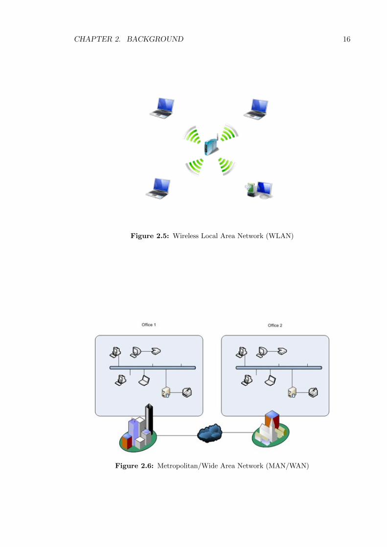
A Wireless LAN is the most widely used wireless technology and it should fulfil
same requirements as of any wired LAN, including fully connected nodes along with
broadcast capacity as shown in Figure 2.5. However, to meet these targets, Wireless
LANs need to be designed in such a way that security, power consumption, mobility,
and bandwidth limitation of the air interface [Sta96] should be considered. Typical

CHAPTER 2. BACKGROUND 15
Figure 2.4: Personal Area Network (PAN)
communication range for WLANs is a single building or a collection of closely lo-
cated buildings.
WLANs can be implemented by following two different approaches like: an in-
frastructure based approach, or an ad hoc approach [Sta96]. In an infrastructure
based approach, a centralized controller normally referred as Access Point (AP) is
used within each cell. The AP may be connected to the wired network to provide the
Internet access to wireless nodes, Whereas, an ad hoc network is a peer-to-peer net-
work formed by a set of wireless nodes within the transmission range of each other.
These nodes dynamically configure themselves to build a temporary network. There
is no requirement of any fixed controller in an ad hoc networks, but a controller may
be dynamically selected among the devices participating in the network.
WAN and MAN ad hoc networks are mobile multi-hop wireless networks that
enable devices to build long range wireless network among multiple locations, e.g,
among multiple offices of a company as shown in Figure 2.6. Radio waves can be
used to transmit data between different locations. At present a lot of things need
to be figure out like addressing schemes, routing protocols, locations and the most
important is security, hence, availability of ad hoc WAN and MAN is not possible
in near future.
All these types of mobile ad hoc networks suffer from different types of security
threats due to their ad hoc nature. These security threats are discussed in detail in
later sections.
CHAPTER 2. BACKGROUND 16
Figure 2.5: Wireless Local Area Network (WLAN)
Figure 2.6: Metropolitan/Wide Area Network (MAN/WAN)

CHAPTER 2. BACKGROUND 17
2.2.2 Characteristics of MANETs
A mobile ad hoc network is a sovereign system of mobile nodes with routing capabil-
ities connected through wireless links, which jointly forms a wireless communication
network [TH06]. Therefore, it can be considered as a temporary infra-structureless
network which is formed by a set of wireless devices that dynamically build their own
network without relying on any central authority [DKB05a]. All participants act as
both hosts and routers forming an autonomous network heavily depended on the
belief that all participants share resources in a fair manner. The nodes are usually de-
vices with limited CPU, storage and energy resources such as mobile phones, PDAs,
laptops and other mobile devices. Moreover, we can easily understand the serious
challenges that exist in the implementation of Mobile ad hoc networks (MANETs).
The foremost characteristics of MANETs, which have an important impact on both
the QoS and the security, are presented in [DKB05a] and are:
• Infra-structureless Nature: MANETs are infra-structureless in nature without
any central servers and fixed routers, therefore, all communication depends on
distributed cooperative schemes instead of a centralized scheme.
• Communication Link: Mobile nodes share wireless link for the communication
between them and this results in security issues like confidentiality, availability,
integrity, anonymity and authorization etc. We described these security issues
in detail in later section. Wireless local area networks (WLANs) face the same
security issues, however, the use of Access Points (APs) gives the opportunity of
applying effective security solutions to WLANs.
• Multi-hop Nature: As mentioned earlier, all nodes participating in an ad hoc
network need to act as a host and routers simultaneously. In fact, the existence
of such networks heavily depends on this feature and at some level the philosophy
of ad hoc networks is based on this feature, namely the trust among nodes which
it is not always guaranteed. Data is transferred from node to node allowing the
connection of distant nodes by the creation of multi-hop routes. However, since
nodes are usually devices with stringent resources some may not be willing to act
as router in order to save resources resulting in connectivity problems.
• Node movement sovereignty: Wireless nodes are mostly sovereign in nature
and are capable of roaming freely. This means that both routing protocols and
security solutions need to be robust to increased mobility.
• Amorphous: Wireless connectivity and node’s movement allow nodes to enter
and exit the network any time, to form new links and break existing links acci-
dentally. The network topology is not fixed but instead it changes in size and

CHAPTER 2. BACKGROUND 18
shape. Therefore, security solutions such as Intrusion Detection Systems (IDS)
are to be considered for inclusion in the solution at built stage.
• Power limitations: Mostly ad hoc nodes are small in size and lightweight in
nature so they have very limited power resources. This power constraint motivates
attackers to target mobile nodes’ batteries to disconnect them from the network
which may lead to network disruption. On the other hand, security solutions
such as cryptographic protocols and embedded IDS need also to be lightweight
and energy conservative in order to be considered as vital solutions.
• CPU and memory limitations: Mobile ad hoc nodes are mostly small in size
and have limited memory and processing powers. Therefore, complex security like
cryptography based solutions are hard to implement.
2.2.3 Applications of MANETs
MANETs play an important role in communication and there are a number of poten-
tial applications available which are very suitable in emergency situations like earth-
quake, fire and floods etc., in battlefields and for meetings or conventions [Per01].
MANETs can also be used for search, rescue and recovery operations in disaster
situations and can also be used as extension in home networks.
Recently, ad hoc networks have become quite popular due to different applica-
tions of MANETs, ranging from small energy constrained to large scale dynamic /
mobile networks. Furthermore, traditional applications also moved from the conven-
tional environment to the mobile ad hoc infra-structureless environment. Therefore,
there are massive applications available that can utilize MANETs but some of the
important applications are listed below [SBP13]:
• Search and rescue based applications
• Defence related applications
• Health care related applications
• Academic based applications
• Industrial or enterprise based applications
2.3 Routing Protocols
Communication in any network (wired or wireless) depends upon routing protocols,
therefore, use of efficient and secure routing protocols is very important for successful

CHAPTER 2. BACKGROUND 19
communication. As MANETs are distinct in nature, therefore, different type of
routing protocol are required, according to the nature of network.
The distinct nature of MANETs results in the evolution of different types of
routing protocols like ARIADNE [HPJ05], DSR [JMB01], ARAN [SLD+05], [RT99],
AODV [PBRD03], TORA [Par01], DSDV [PVA+10a]. Generally, these protocols are
classified into three major groups:
1. Table-driven routing protocols (Proactive)
2. On-demand routing protocols (Reactive)
3. Hybrid (Cluster based approach)
In table-driven routing protocols, each participating node retains routing table
which contains routing information to other nodes present in the network. All nodes
update their routing tables in order to keep a consistent and up-to-date routing in-
formation of the network after a specific time period. When a change occurs in
topology, nodes then propagate update messages throughout the network. Then
other nodes will be able to update their tables according to the message. Besides,
nodes also inform other nodes about their status information by periodically prop-
agating status messages. Through active information exchanging, all the nodes will
be able to finally obtain the up-to-date topology information. When there is data
to be sent, nodes can simply search their tables and extract the route. It is an
proactive approach to conduct routing and is similar to the one used for routing in
wired IP networks, e.g, OSPF [Moy97].
Proactive routing protocols for ad hoc networks are Optimised Link-State Rout-
ing (OLSR) [OLS03], Destination Sequenced Distance Vector (DSDV) [PVA+10a],
Wireless Routing Protocol (WRP) [Mla95] and Cluster-head Gateway Switch Rout-
ing protocol (CGSR) [LCWG97] etc. The preeminent disadvantages of this approach
are sufficient amount of data is required to be transfer for route maintenance, slow
reaction on route restructuring and routes failures because every node needs to up-
date its tables and also propagate updated information to others in timely manner.
In on-demand routing protocols, whenever there is a requirement, routes are
created. In this approach, nodes do not propagate the topology status to each other
and keep the topology info for the whole network. Whenever a node needs to send
data to a specific destination, it generates a route request by flooding the route re-
quest packets to find out the suitable route between the source and the destination.
This route will remain valid until a failure on this route is detected. Ad hoc On de-
mand Distance Vector (AODV) [PBRD03], Temporally Ordered Routing Algorithm

CHAPTER 2. BACKGROUND 20
(TORA) [Par01] and Dynamic Source Routing (DSR) [JMB01] routing protocol are
examples of reactive protocol for ad hoc networks. The main disadvantages of this
approach are excessive flooding and high latency time in route discovery which may
lead to network clogging.
In hybrid routing protocol, advantages of both proactive and reactive routing
protocols combined to get better and efficient routes. The hybrid routing is origi-
nally established with the help of proactive routing and then serves the demand of
additional nodes through reactive flooding. Zone Routing Protocol (ZRP) [Bei] is
an example of hybrid routing protocol for MANETs. The main disadvantages of
such routing protocols are reaction to traffic demand depends on gradient of traffic
volume and on amount of nodes activated. Figure 2.7 depicts various types of ad
hoc routing protocols.
Figure 2.7: Types of wireless ad hoc routing protocols
Usually on-demand approach is more preferable than others in ad hoc networks
because mobile devices like Laptops, PDAs, mobile phones are usually constrained
by their memory size and battery life. One other important factor is availability of
bandwidth as compared to wired networks. Therefore, on-demand routing protocols
are preferred because there is no need to have large memory to store routing tables.
In on-demand approach, the bandwidth and battery life are saved as there is no
need of periodic propagated messages. In the following subsections, we discuss some
of the commonly used routing protocols in mobile ad hoc networks.

CHAPTER 2. BACKGROUND 21
2.3.1 OLSR
The Optimized Link State Routing (OLSR) [OLS03] protocol is a table driven proac-
tive routing protocol for MANETs. OLSR optimizes the flooding of route requests
and reduces the overheads of control messages by marking subset of neighbours as
multi-point relays (MPRs). The OLSR can be branched into following three mod-
ules:
• Neighbour / link sensing: All nodes broadcast HELLO packet to sense neighbours
and links on a specific interval.
• Optimized flooding / forwarding (Multipoint Relaying): Multipoint relaying re-
duces the number of duplicate retransmissions while forwarding a broadcast packet
and restricts the set of nodes retransmitting a packet from all the nodes to a subset
of all nodes.
• Link-State messaging and route calculation: To minimize the size of link-state
messages, only multipoint relay (MPR) selectors are declared and only MPR
nodes generate link-state message. This results in optimized routing. Figure 2.8
shows the routing process of OLSR protocol.
Figure 2.8: OLSR Routing Mechanism [OLS03]

CHAPTER 2. BACKGROUND 22
2.3.2 WRP
The WRP (Wireless Routing Protocol) [Mla95] is a proactive table-based distance
vector routing protocol for mobile ad hoc networks. Each node in the network
maintain following tables:
• Distance table
• Routing table
• Link-cost table
• Message retransmission list (MRL) table.
Each entry of the MRL table contains the sequence number of the updated
message, a retransmission counter, an acknowledgement-required flag vector with
one entry per neighbour, and a list of updates sent in the update message. The
MRL records which updates in an update message need to be retransmitted and
which neighbours should acknowledge the retransmission. Nodes exchange routing
tables with their neighbours through update messages periodically as well as on any
link changes. All the recipients of update message are required to acknowledge the
receipt of updated message. A unique feature of this algorithm is that it checks
the consistency of all its neighbours every time it observes any change in any of the
links. Consistency check in this helps in elimination of looping situations and also
has fast concurrence.
2.3.3 AODV
Ad hoc On Demand Distance Vector (AODV) [PBRD03] is one of the most popular
on demand routing protocol, in which routes from source to the destination are only
identified when required, to avoid memory and power overheads. It emerged as an on
demand version of distance vector routing protocol [LWZB03], which is based on the
classical Distributed Bellman-Ford (DBF) algorithm [DB92]. In AODV, a node does
not need to maintain any routing information to other nodes until communication
is required between them. The routing messages in AODV are not big in size
because they only contain information about the source and the destination. All
these features enable AODV to be a suitable routing protocol for MANETs. Steps
involved in AODV routing are discussed in detail in Chapter “Multirate DelPHI”.
2.3.4 DSR
Dynamic source routing (DSR) protocol [JMB01], is an on-demand routing protocol
based on the concept of source routing, which means the initiator knows the complete

CHAPTER 2. BACKGROUND 23
hop-by-hop route to the destination. This specific feature brings efficiency, but also
results in the scaling of routing message overhead. To perform DSR, each node
is required to maintain a route cache which contains the topology information of
the network. The route cache is consistently updated to reflect the current status
of the network. Steps involved in DSR routing are discussed in detail in Chapter
“Multirate DSR”.
2.3.5 Zone Routing Protocol (ZRP)
ZRP (Zone routing protocol) [Bei] is a hybrid routing protocol for mobile ad hoc
networks. This protocol segregate the network into different non-overlapping routing
zones and runs separate protocols that work within and between these routing zones.
IARP (Intra-zone protocol) operates within a zone, and determines all the possi-
ble routes within that zone and all nodes within that zone know about zone topology.
Intra-zone protocol is not defined but any proactive protocol can be used, such as
DSDV. Different proactive routing protocols can be used in different zones simulta-
neously.
IERP (Inter-zone protocol) operates between different zones and is reactive in
nature. If a source node wants to communicate with a destination which is not
located within the same zone, source sends route request (RREQ) packet to all
border nodes of its zone. This continues until destination is found. Routing zone
diameter is variable and this should be chosen optimal for a scaled topology. By
zoning, the overhead of control messages is attempted to be kept lower.
2.4 MANET based on IEEE 802.11
Mobile ad hoc networks consist of wireless nodes communicating with each other
through wireless medium directly or indirectly with the help of neighbouring nodes.
MANETs have gained more and more popularity because of easy deployment and
low cost. Moreover, MANETs support both single rate and multirate transmissions
depending upon physical carrier sensing ranges, and SINRs (Signal-to-Interference
and Noise Ratio) for different transmission rates [LSFZ09].
The IEEE 802.11 MAC protocol is used as a standard for MANETs and is
responsible for the coordination of transmissions on a common wireless medium.
As mentioned in [SGTL11], IEEE 802.11 standard has distinct variants like IEEE
802.11a, IEEE 802.11b, IEEE 802.11g, IEEE 802.11n and more recently IEEE
802.11ac. All of these support different coverage areas and even different signal
strength within that coverage area.
CHAPTER 2. BACKGROUND 24
2.4.1 IEEE 802.11b
The IEEE 802.11b works in 2.4GHz frequency band. It uses Complementary Code
Keying (CCK) and Quaternary Phase Shift Keying (QPSK) modulation to get a
maximum transfer rate of 11Mbps. However, theoretically data transfer rate in
IEEE 802.11b cannot exceed 6Mbps with Transmission Control Protocol (TCP)
and 7Mbps with User Datagram Protocol (UDP).
This protocol can be used in point-to-point and point-to-multipoint topologies
with links over distances proportional to the antennas’ output power. Moreover, if
signal quality is not good due to any reason, data transfer may reduced to 5.5Mbps
or 2Mbps or 1Mbps, using redundant methods of data encryption.
2.4.2 IEEE 802.11g
IEEE 802.11g works in 2.4GHz frequency band and is compatible with IEEE 802.11b.
Theoretical data transfer rate is 54Mbps, which is not practically possible and is
reduced to 22Mbps when the receiver is some meters away. It also uses 52 sub-
carriers.
IEEE 802.11g uses orthogonal frequency division multiplexing (OFDM), same
as 802.11a, with data rates of 6Mbps, 9Mbps, 12Mbps, 18bps, 24Mbps, 36Mbps,
48Mbps, and 54Mbps. It reverts to Complementary Code Keying (CCK) similar
to 802.11b for 5.5Mbps and 11Mbps. IEEE 802.11g also suffers from the same
interference as IEEE 802.11b and there is decrease in data transfer rate according
to the signal strength.
As IEEE 802.11g uses the same radio signalling CCK (Complementary Code
Keying) as 802.11b, at the lower four IEEE 802.11g data rates, so it is fully back-
ward compatible with 802.11b. This enables IEEE 802.11b/g wireless networks to
continue supporting only IEEE 802.11b enabled devices. IEEE 802.11g may seem to
be the competence of 802.11a, but most products include both technologies because
they are complementary.
2.4.3 IEEE 802.11a
The IEEE 802.11a works in the 5GHz frequency band and uses Orthogonal Fre-
quency Division Multiplexing (OFDM) modulation with 52 sub-carriers. This stan-
dard has a theoretical maximum speed of 54 Mbps, but the transmission rate de-
pends upon the signal quality and it decreases with decrease in signal strength.
54Mbps can be decreased to 48Mbps, 36Mbps, 24Mbps, 12Mbps, 9Mbps and 6Mbps
according to signal strength. From a total of 52 sub-carriers, 48 are used for the
data transmission where as rest of 4 are used for pilot tasks, with a separation

CHAPTER 2. BACKGROUND 25
of 312.5KHz. Each sub-carrier may be modulated by different modulation scheme
like Binary Phase Shift Keying (BPSK), Quaternary Phase Shift Keying (QPSK),
Quadrature Amplitude Modulation (16-QAM) or (64-QAM).
In IEEE 802.11a, there are 12 non-overlapping channels available and as it
uses the 5GHz band, the signal has less interference than the other IEEE 802.11
standards. But the issue is that the equipment must be in the line of sight (LOS)
to get maximum benefit in communications.
2.4.4 IEEE 802.11n
IEEE 802.11n significantly improves the network performance of preceding standards
such as 802.11a/b/g. IEEE 802.11n is built on existing standards with extra feature
of MIMO (Multiple Input Multiple Output) and binding of network interfaces for
channel bonding.
Theoretically, it supports data transfer rate upto 600Mbps but currently it sup-
ports rate of 450Mbps physically by using 3 spatial streams in a 40MHz channel.
Moreover, IEEE 802.11n uses MIMO with the help of multiple transmit and receive
antennas which results in improvement in system performance. This technology re-
quires a separated radio frequency and also an analog to digital converter for each
MIMO antenna which results in increase in the implementation cost as compared
to the systems without MIMO technology.
Table 2.1 summarizes the main characteristics of the four variants of the IEEE
802.11 standard.
IEEE 802.11a IEEE 802.11b IEEE 802.11g IEEE 802.11n
Frequency Band 5.7 Ghz 2.4 Ghz 2.4 Ghz 2.4/5 Ghz
Theoretical Speed 54 Mbps 11 Mbps 54 Mbps 248 Mbps
Modulation OFDM CCK,QSPK DSSS,CCK,OFDM OFDM
Channel Bandwidth 20 Mhz 20 Mhz 20 Mhz 20/40 Mhz
Radio Interference Low High High Low
Cost Medium-Low Low Low High-Medium
Mobility Yes Yes Yes Yes
Usage Low Medium High High
Security Medium Medium Medium High
Table 2.1: IEEE 802.11 standards comparison [SGTL11]
2.4.5 Multirate Transmission in IEEE 802.11
IEEE 802.11 standards support multirate transmissions in wireless ad hoc networks.
The transmission rate is directly proportional to channel quality at the physical

CHAPTER 2. BACKGROUND 26
layer, whereas, channel quality is usually determined by the distance between wire-
less nodes. If the distance increases than the channel quality decreases and results
in low transmission rate and vice versa. Another important factor is that wireless
nodes in MANETs are not static and are moving within the network at specific speed
which increase/decrease the distance between them. This change in the distance af-
fects the transmission rate between them. For example, two neighbouring nodes ’a’
and ’b’ might have high transmission rate depending upon network structure and
protocol but if the nodes are dynamic and the distance between them increase or
decrease with their movement, it results in high or low transmission rate between
them.
In [AHR04], authors discuss the multirate transmission model for IEEE 802.11b
standard and run simulations to show the maximum range at different transmission
rate. They use NS2 [ns2] to run simulations and parameters defined by them are
shown in Table 2.2.
Parameter ValueFrequency 2.4 GHzTransmit Power 14 dBm11 Mbps receive Threshold -82 dBm5.5 Mbps receive Threshold -87 dBm2 Mbps receive Threshold -91 dBm1 Mbps receive Threshold -94 dBmCarrier Sense Threshold -108 dBmCapture Threshold 10Propagation Model Two Ray GroundSystem Loss 0 dBm
Table 2.2: Simulation Parameters for Multirate IEEE 802.11b [AHR04]
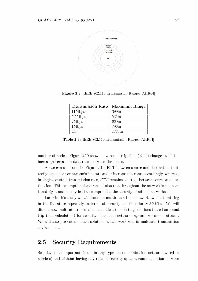
Figure 2.9 and Table 2.3 show the maximum transmission ranges based on dif-
ferent transmission rates. In real time scenario, these transmission ranges are sub-
stantially smaller because of actual system losses, additional noise or propagation
delays. These results only show that how transmission rate effects the transmission
range and vice versa.
In order to further investigate the effects of multirate transmission in ad hoc
networks in comparison with constant transmission rate, we have conducted some
simulations using NS2 [ns2]. Simulation parameters are defined in Table 2.4 be-
low. We randomly distributed wireless nodes in specific area and then randomly
selected source and destination pairs. Different bandwidths were assigned between
the node pairs to highlight the effect of multirate environment. More than 100
simulations were run with different data rates between node pairs and for different
CHAPTER 2. BACKGROUND 27
Figure 2.9: IEEE 802.11b Transmission Ranges [AHR04]
Transmission Rate Maximum Range11Mbps 399m5.5Mbps 531m2Mbps 669m1Mbps 796mCS 1783m
Table 2.3: IEEE 802.11b Transmission Ranges [AHR04]
number of nodes. Figure 2.10 shows how round trip time (RTT) changes with the
increase/decrease in data rates between the nodes.
As we can see from the Figure 2.10, RTT between source and destination is di-
rectly dependant on transmission rate and it increase/decrease accordingly, whereas,
in single/constant transmission rate, RTT remains constant between source and des-
tination. This assumption that transmission rate throughout the network is constant
is not right and it may lead to compromise the security of ad hoc networks.
Later in this study we will focus on multirate ad hoc networks which is missing
in the literature especially in terms of security solutions for MANETs. We will
discuss how multirate transmission can affect the existing solutions (based on round
trip time calculation) for security of ad hoc networks against wormhole attacks.
We will also present modified solutions which work well in multirate transmission
environment.
2.5 Security Requirements
Security is an important factor in any type of communication network (wired or
wireless) and without having any reliable security system, communication between

CHAPTER 2. BACKGROUND 28
Terrain Area 1500m X 1500m
Number of Nodes 50/100/150
Tx Range(r) 150m
Transmission Rate 2Mbps− 54Mbps
Routing Protocol AODV
Network Topology IEEE802.11g
Addressing Mode IPV 4
Packet Size 512Bytes
Minimum Node Speed 0m/s
Maximum Node Speed (2/5/10)m/s
Table 2.4: Simulation Inputs
Figure 2.10: RTT Calculation in Multirate Transmission
users is at high risk. Security of MANETs is easier to be compromised and is hard
to implement as compared to wired networks because of following characteristics of
MANETs [DKB05a]:
• Lack of a trusted centralized authority
• Shared wireless medium
• Dependence upon neighbours for routing and data transfer
• Dynamic nature of topology
• Resource constraints (CPU, Memory and Power etc)
In the following subsections, we first identify general security requirements for
any type of communication network regardless of wired or wireless. Then we discuss
about different types of attacks and then security threats in MANETs.

CHAPTER 2. BACKGROUND 29
2.5.1 General Security Requirements
Communication networks either wired or wireless both share mostly the same secu-
rity requirements. The goal of these requirements is to protect user information and
resources from attacks and misbehaviour. In terms of network security, the follow-
ing requirements are important and must be ensured in any security architecture
[DKB05a] and [LJ]:
• Availability: It ensures that the desired network services are available whenever
they are required, regardless of the presence of any attack. This is mainly chal-
lenged during DOS (denial of service) attack, energy starvation attacks and node
misbehaviour (node selfishness in packet forwarding).
• Confidentiality/Privacy: Confidentiality means that message/data sent over
the communication channel is readable by the authorised user only. In order to
achieve the confidentiality, we can use symmetric or asymmetric data encryption
to keep data secret from all entities that do not have the privilege to access it.
• Integrity: It ensures the data sent from one node to other node is not altered or
modified by any unauthorized node during the whole communication process. If
a robust confidentiality mechanism is employed, ensuring data integrity may be
as simple as adding one-way hashes [Sta] before encrypting messages.
• Non-repudiation: It ensures that a node can not deny the sending of a message
which is originated by that node. This is very useful in discriminating a node
with some abnormal behaviour to check whether it is compromised or not. Digital
signatures [Sta] can be used to implement non-repudiation.
• Anonymity: Anonymity means that all the information related to identification
of a node should be kept secret and not be distributed by the node itself or the
system.
• Authentication: It ensures that communication between nodes is genuine and
malicious node cannot masquerade as a trusted network node.
• Authorization: It ensures that whether specific node is authorized to do specific
task or not.
2.5.2 General Security Threats
Networking either wired or wireless always suffers from different type of security
threats [Bur03a], which can be classified according to their origin or their nature.
In [DKB05a], authors classify the attacks according to their nature to external or

CHAPTER 2. BACKGROUND 30
internal attacks. In addition, a nature based classification splits them into passive
or active attacks.
• External attacks: are normally launched by external nodes that are not legally
part of the network.
• Internal attacks: are launched by internal nodes (compromised or malicious).
This type of attack is more dangerous in nature because security solutions against
external attacks are inefficient to detect internal attacks.
• Passive attacks: These attacks do not disrupt any of the services provided by
the network but they simply try to get information about the network and listen
to network communication. These attacks might aid other intruders at later stage
in launching an active attack.
• Active Attacks: These attacks actively modify the network data, with the in-
tention of overloading the network traffic, disturbing the network operation or
block certain nodes to communicate with their neighbours so that they can not
use the network productively.
External attacks can be prevented with the help of a firewall or proxy server
whereas, detection of internal attacks is much more difficult because these are per-
formed by network peers. Passive attacks do not disturb routing operations, but
they are usually the first step of launching other active attacks. By eavesdropping
communication, attackers may be able to learn the topology information, such as
which node is the bottleneck of the network, and then launch attacks against that
node. There are also some sophisticated attacks, exploiting design flaws of basic
routing protocols, including black hole [HP04] and rushing attacks [HPJ03b]. Some
other common attacks which suffer routing and communication in wireless and wired
networks are as under:
• Attacks by modification of routing information: This kind of attacks
[GS03, SEDL03] are performed by modifying the routing information. In wireless
routing, network topology is maintained by flooding routing information through
out the network. Any wrong updation or alteration in these messages will cause
topology change, which effects the network communication. Current ad hoc rout-
ing protocols generally assume that nodes will not alter the routing message fields,
which makes this kind of attack extremely easy to be launched.
• Attacks by spoofing: Spoofing [GS03, SEDL03, Bur03b, Cho03] means an
attacker assumes the identity of another node and start receiving messages that
are directed to the original node. This kind of attack is commonly known in wired

CHAPTER 2. BACKGROUND 31
networks, but becomes more dangerous in wireless networks. Because usual ad
hoc routing protocols do not validate the source IP address, so attackers can easily
masquerade the other nodes. It is usually the first step to intrude a network so
as to carry out further attacks to disrupt operations.
• Attacks by fabrication: These attacks are usually conducted by generating
false routing messages to disturb network topology [GS03]. It is known as route
misbehaviour, which is very difficult to detect. AODV and DSR are especially
vulnerable to this kind of attack. In AODV, an intruder can prevent communica-
tion between any two nodes by flooding spoofed RRER messages along the path.
RRER messages claim that the next hop of the source is not available at the mo-
ment. All the nodes receiving this message mark this link as “broken”. Further,
a malicious node can continue sending spoofed RRER if the link is re-established,
resulting in complete isolation of a targeting node.
• MAC layer attacks: In MANETs, there are some other security threats which
disturb smooth communication at MAC layer are Man-in-the-middle, ARP spoof-
ing and ARP poisoning [FD01]. To reduce the no of ARP (Address Resolution
Protocol) packets to be broadcasted, operating systems keep a record of ARP
replies received from other nodes. When a node receives an ARP reply, it up-
dates its ARP table with the new IP / MAC mapping. As ARP is a stateless
protocol, most operating systems update their ARP table blindly if they receive
a ARP reply packet, without even sending an actual request. ARP spoofing is
involved in construction of forged ARP request and reply packets. By sending
forged ARP replies, a target node could be convinced to send frames destined
for node A to instead go to node B [BBM98, FMMT84]. When done properly,
computer A will have no idea that this redirection took place. The process of
updating a target computer’s ARP cache with a forged entry is referred to as
“poisoning”. However, using ARP spoofing, “man-in-the-middle (MITM)” at-
tack can be launched in the network as shown in Figure 2.11. When a MITM
is launched, an intruder inserts his device between the communication path of
two targeted nodes. The intruder then forwards frames between the two targeted
nodes so communications are not interrupted [NTCS99]. The attack is performed
as follows (where C is the attacking computer, and A and B are targets):
-C poisons the ARP cache of A and B.
-A associates B’s IP with C’s MAC.
-B associates A’s IP with C’s MAC.
-All of A and B’s IP traffic will then go to C first, instead of directly to each other.

CHAPTER 2. BACKGROUND 32
Figure 2.11: Man-in-the-middle attack [QMS08]
2.5.3 Security Threats in MANETs
MANETs lack a clear physical boundary and all nodes can hear the communication
of neighbouring nodes working in the same frequency channel [IH+08]. If the node
cannot differentiate between the packets transmitted by an authorised node from
the ones transmitted by an intruder, then the security of legitimate node is at high
risk. An intruder can easily do the following:
1. Motivate its neighbours to accept misleading information
2. propagate unnecessary traffic and misleading information to other parts of the
network as well.
In the wireless networks, it is easier to make eavesdropping than a wired network.
If the packets are not encrypted properly, eavesdroppers can make unauthorised use
of the received information and cause trouble. For example, an eavesdropper can
forward unencrypted routing information to an accomplice to disrupt the normal
operation of the network.
For the aforementioned reasons, security of mobile ad hoc networks is a pri-
mary concern in order to provide secure communication among the mobile nodes
in a potentially hostile environment [YLY+04]. Resource constraints (e.g., CPU or
battery), dynamic network topology, and infra-structureless environment make the
security issues more demanding.
Ad hoc networks are susceptible to different types of attacks due to their nature
and features at different protocol layers. Figure 2.12 displays the summary of attacks
against each protocol layer in mobile ad hoc networks.

CHAPTER
2.BACKGROUND
33
Figure 2.12: Attacks on each layer in Mobile Ad hoc Networks

CHAPTER 2. BACKGROUND 34
Routing in mobile ad hoc networks depends upon the cooperation of all the nodes
and their fair behaviour because of multihop in nature. Secure routing in MANETs
can only be achieved by securing the network layer of the protocol stack. Figure
2.12 clearly shows that network layer is more prone to different types of attacks
as compared to other layers, therefore, it is very important to secure MANETs
against network layer attacks. These attacks can lead to some other attacks as
well and also disrupt the routing and data transfer among the mobile nodes. This
results in degradation of overall performance and use of MANETs in any scenario
(disaster/recovery or defence etc).
2.5.4 Security Threats against Routing in MANETs
In MANETs, security of routing protocols can easily be compromised as compared to
wired networks due to shared wireless medium and lack of any central authority. In
MANETs, threats against routing protocols are mainly divided into two categories
[ZL05]:
• Attacks on routing protocols: These types of attacks mainly block the prop-
agation of routing information and disrupt routing between the nodes.
• Attacks on packet forwarding or delivery: These types of attacks try to
disturb the packet delivery along a predefined path.
There are some other threats as well against routing that have been discussed
in the literature [PH02], [HPJ05], [SDL+02] and [HJP03] etc.:
• Acting as an another node to spoof routing packet.
• Advertising a false route to distort the network topology.
• Sending a route message with wrong sequence number to conceal other legitimate
route messages.
• Flooding Route Discovery to achieve DoS attack.
• Modifying a Route Reply packet to inject a false route.
• Generating bogus Route Error to disrupt a working route.
• Suppressing Route Error to mislead others.
Due to mobility factor and dynamic network topology of MANETs, it is hard
to validate all the routing packets all the time [ZL05]. There are some other routing

CHAPTER 2. BACKGROUND 35
attacks which are easy to implement and hard to detect like Wormhole attacks
[HPJ03a], Rushing attacks [HPJ03b] and Sybil attacks [Dou02].
The second type of routing attacks are based on attacks on packet forwarding
or delivery, which are also not easy to detect and prevented [ZL05]. These types of
attacks are implemented due to selfish nature of normal or malicious nodes.
In this thesis, our focus is on network layer attack that is wormhole attacks
in mobile ad hoc networks because wormhole attacks can further aid to blackhole,
grayhole and Man-in-the-Middle attacks. In the next subsection, we briefly discuss
about wormhole attacks and its different modes.
2.6 Wormhole Attacks
Wormhole attack is one of the severe attacks, which was introduced in the context
of ad hoc networks [HPJ06], [WBLW06a]. In this attack, a malicious node captures
packets from one location in the network, and tunnels them to another malicious
node at a distant point, which replays them locally. The tunnel can be established
in many different ways, e.g., through an out-of-band hidden channel (e.g., a wired
link), a packet encapsulation, or a high powered transmission. This makes the
tunnelled packet arrive either sooner or with a lesser number of hops compared to
the packets transmitted over normal multihop routes. This creates the illusion that
the two end points of the tunnel are very close to each other. A wormhole tunnel can
actually be useful if used for forwarding all the packets. However, in its malicious
incarnation, it is used by attacking nodes to subvert the correct operation of ad hoc
and sensor network routing protocols. The two malicious end points of the tunnel
may use it to pass routing traffic to attract routes through them. They can then
launch a variety of attacks against the data traffic flowing on the wormhole, such as
selectively dropping the data packets. The wormhole attack can prevent two nodes
from discovering legitimate routes greater than two hops away and thus disrupt
network functionality [QRMS13]. In addition, it may affect data aggregation and
clustering protocols and location-based wireless security systems. It is important to
note that the wormhole attack can be launched even without having access to any
cryptographic keys or compromising any legitimate node in the network [HPJ06],
[WBLW06a].
2.6.1 Modes of Wormhole attacks
There are different ways to launch wormhole attacks in a wireless network environ-
ment which include using high power transmission, tunnelling using encapsulation,
tunnelling using out-of-band channels, packet relay or protocol deviation [KBS05].

CHAPTER 2. BACKGROUND 36
These will be discussed in detail in the ensuing paragraphs.
• Wormhole using High Power Transmission: In this mode, a single malicious
node can create a wormhole attack without the help of any colluding node. When
a malicious node gets a route request, it broadcasts the request with high power
as compared to normal nodes. Any node that hears the high-power broadcast,
rebroadcasts it towards the destination. By this method, the malicious node
increases its chance to inject itself in the routes established between the source
and the destination.
• Wormhole Tunnel using Encapsulation: In this mode of attack, two or more
malicious nodes participate to create a tunnel between them and give false illusion
that the route through them is the shortest, even though that may not be the
case. They create a tunnel with the help of normal nodes using encapsulation.
Due to encapsulation, hop count does not increase during the traversal through
intermediate nodes of tunnel, which launches wormhole attack between source
and destination.
As shown in Figure 2.13, in which the source node S tries to find out the short-
est path for the destination D, in the presence of two malicious nodes M1 and
M2. Node S broadcasts a route request (RREQ) packet for the destination node
D, M1 hears that request, encapsulates it and forward it to M2 through the
intermediate nodes (E,F,G). Upon reception of the request packet, M2 de-
encapsulates the request packet and rebroadcasts it again, which is received by
D. Due to encapsulation of request packet by M1, hop count doest not in-
crease during the traversal through E, F , G. On the other side, request packet
from S to D through A, B, C. Now destination node D has two routes, the
first is three hop long (S → M1 → M2 → D), whereas second route is four
hop long (S → A → B → C → D). Therefore, destination D will select first
route because it appears to be the shortest path but in fact it is six hops long
(S → M1 → E → F → G → M2 → D). Hence malicious nodes M1 and M2
have successfully created the wormhole tunnel and also got the ability to monitor
communication between S and D.
• Wormhole Tunnel using Out-of-Band Channel: In this mode of attack, an
out-of-band high-bandwidth channel between the malicious nodes is used to create
a wormhole tunnel. This channel can be a long-range directional wireless link or
a direct wired link. This type of attack requires specialized hardware, therefore,
it is more difficult to launch as compared to encapsulation attack.
As shown in Figure 2.14, Node S sends a route request for node D, whereas
M1 and M2 are malicious nodes having an out-of-band channel between them.
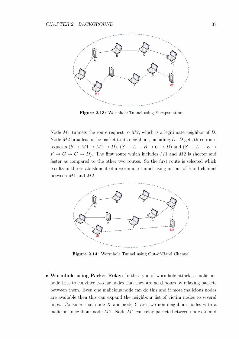
CHAPTER 2. BACKGROUND 37
Figure 2.13: Wormhole Tunnel using Encapsulation
Node M1 tunnels the route request to M2, which is a legitimate neighbor of D.
Node M2 broadcasts the packet to its neighbors, including D. D gets three route
requests (S → M1→ M2→ D), (S → A→ B → C → D) and (S → A→ E →F → G → C → D). The first route which includes M1 and M2 is shorter and
faster as compared to the other two routes. So the first route is selected which
results in the establishment of a wormhole tunnel using an out-of-Band channel
between M1 and M2.
Figure 2.14: Wormhole Tunnel using Out-of-Band Channel
• Wormhole using Packet Relay: In this type of wormhole attack, a malicious
node tries to convince two far nodes that they are neighbours by relaying packets
between them. Even one malicious node can do this and if more malicious nodes
are available then this can expand the neighbour list of victim nodes to several
hops. Consider that node X and node Y are two non-neighbour nodes with a
malicious neighbour node M1. Node M1 can relay packets between nodes X and

CHAPTER 2. BACKGROUND 38
Y to give them the illusion that they are neighbours.
• Wormhole using Protocol Deviations: Some routing protocols, such as ARAN
[SLD+05], choose the route with the shortest delay in preference to the one with
the shortest number of hops. During the route request forwarding, the nodes
typically back off for a random amount of time before forwarding. This is moti-
vated by the fact that the request forwarding is done by broadcasting and hence,
reducing MAC layer collisions which is important. A malicious node can create a
wormhole by simply not complying with the protocol and broadcasting without
backing off. The adversaries purpose is to let the request packet it forwards arrive
first at the destination thereby increasing the chances of being included in the
path. This is a special form of the rushing attack described in [HPJ03b].
Wormhole attacks are very easy to implement in wireless ad hoc networks
whereas hard to detect as discussed in earlier sections. Wormhole attacks can also
act as the first stage attackers where they can lead to different types of attacks as
mentioned below:
• Man-in-the-middle (MITM) attacks
• Denial-of-Service (DOS) attacks
• Black hole attacks
• Gray hole attacks
In the second stage, wormhole attacks may compromise the security of the global
network as that breaks confidentiality and integrity. The wormhole attack is very
harmful to the security of network. Due to the placement of the wormhole in the
network there will be significant breakdown in communication across a wireless net-
work. A successful wormhole attack may be the reason of disruption and breakdown
of a network. Proper balance between these two is necessary to prevent much con-
sumption of resources.
2.7 Summary
During the last two decades, MANETs have been broadly reviewed by the re-
searchers. Due to development and advancement in wireless equipment and com-
munication technology, wireless ad hoc networks attracted various commercial and
defense applications. Nevertheless, it also increased the responsibility of researchers
to provide efficient and secure solutions for them. Security of mobile ad hoc net-
works is the major concern because of dynamic nature, shared wireless medium and
infra-structureless network.
CHAPTER 2. BACKGROUND 39
In this chapter, we briefly discussed about mobile ad hoc networks and their
security threats. We discussed the architecture of ad hoc networks, their charac-
teristics, types and applications. We also discussed different routing protocols for
mobile ad hoc networks including reactive, proactive and hybrid. We also presented
detailed working of some of the routing protocols which we further used in our work
in this thesis like AODV, DSR and OLSR etc.
The main important aspect of our work presented in later chapters is the con-
sideration of multirate transmission in MANETs which is missing in the existing
solutions against wormhole attacks. We discussed this in detail along with some
simulation results that how multirate transmission affects the round trip time (RTT)
between the nodes, how it affects the overall network performance and how it af-
fects the detection of wormhole attacks. We also discussed IEEE 802.11a/b/g/n/ac
standards and their transmission ranges and data transfer speeds.
We also discussed security requirements in general and then security threats to
wireless ad hoc networks including types of threats like what are internal, external,
active and passive attacks. Then we focused on wormhole attacks in detail which is
main security concern in this thesis. We also discussed different modes of wormhole
attacks and also discussed how these modes can be implemented and how dangerous
is the effect on wireless ad hoc networks. We also mentioned that wormhole attacks
may act as first stage attack and may lead to some other threats like MITM, DOS,
Black hole and gray hole etc. attacks.
In the next chapter, we give a deep review of the literature regarding wormhole
attacks in MANETs. It will become evident that the state of the art has made some
assumptions about the physical channel which are not realistic and hence have lead
to optimistic results being obtained.

Chapter 3
Literature Review
3.1 Introduction
In this chapter, we review existing solutions against wormhole attacks in wireless
mobile ad hoc networks. A number of solutions has been presented in order to secure
mobile ad hoc networks but still there are many more threats to be secured yet. As
we discussed earlier that wormhole attack is one of the severe attacks and is easy to
implement in mobile ad hoc networks but hard to detect. Different types of security
solutions are proposed by the researchers since identification of wormhole attacks.
These solutions can be categorised based on their nature into the following types:
• Hardware/Software based Solutions
• Statistical/Graph Analysis based Solutions
• Challenge/Response based Solutions
• Round Trip Time (RTT) based Solutions
• Intrusion Detection based Solutions
We describe all types of solutions against wormhole attacks in detail and also
describe a comprehensive comparison of these solutions based on the following pa-
rameters:
• Network Type (NT)
• Routing protocol (RP)
• Extra hardware(EH) requirements
• Clock Synchronization (CS) requirements
• Type of wormhole detected (In or Out)
• Wormhole nodes identification (WID)
• False Detection (FD)
• Multirate transmission (MT) considered or not
40

CHAPTER 3. LITERATURE REVIEW 41
Figure 3.1: The Structure of Literature Review
3.2 Hardware/Software based solutions
In this section, we discuss hardware or software based solutions against wormhole
attacks. In these types of solutions, authors used different types of special hardware
devices such as Global Positioning System (GPS), directional antennas or tightly
synchronized clocks or special softwares to secure ad hoc networks against wormhole
attacks. These solutions are not suitable for all types of mobile ad hoc networks
especially in disaster and emergency scenarios.
These extra hardware/software based solutions provide security but sometimes
their implementation cost is too high like price of extra hardware/software, power
consumption, memory usage etc. We describe some of the popular hardware/software
based solutions against wormhole attacks in detail.
In [HPJ03a], Hu, Perrig and Johnson introduced the concept of a temporal and
geographical leashes to detect wormhole attacks in wireless networks. According
to the authors, each node needs to know its own location (with the help of GPS)
and all nodes have synchronized clocks. Temporal leash in the packet ensures that
the packet has an upper bound on its lifetime, which restricts the maximum travel
distance, since the packet can travel at most at the speed of light. Detection process
for wormhole attack by the temporal leashes can be described as follow:

CHAPTER 3. LITERATURE REVIEW 42
• When sending a packet at local time ts, in order to prevent the packet to travel
further than distance L, the sender needs to set the packet expiration time to
te = ts + L / c − M (All nodes are time synchronized up to a maximum time
synchronization error M and c is the propagation speed of wireless signal).
• When the receiver gets the packet at local time tr, it further processes the packet
if the temporal leash is not expired (i.e; tr < te), otherwise it drops the packets.
The geographical leashes ensure that the distance between sender and recipient
is within certain limits. Detection process for wormhole attack by geographical
leashes can be described as follows:
• When sending a packet, the sending node includes in the packet its own location
ps, and the time at which it sent the packet ts.
• When receiving a packet, the receiving node compares these values to its own
location pr, and the time at which it received the packet tr.
• If the clocks of the sender and receiver are synchronized to within ± M, and v is
an upper bound on the velocity of any node, then the receiver can compute an
upper bound on the distance between the sender and itself dsr.
• Given the timestamp ts in the packet, the local receive time tr, the maximum
relative error in location information δ and the locations of the receiver pr and the
sender ps then dsr can be bounded by dsr ≤ ‖ ps − pr ‖ + 2v(tr − ts + M) + δ.
Authors made an implicit assumption that packet processing, sending, and re-
ceiving delays are negligible. Both geographical and temporal leashes need to add
authentication data to each packet to protect the leash, which add significant pro-
cessing and communication overhead. In addition, a large amount of storage is
needed at each node since a hash tree based authentication scheme (Merkle hash
trees) is used in [Mer80].
In [WBLW06b], Wang et al. proposed an end-to-end wormhole detection mecha-
nism. The basic idea is to use an end-to-end mechanism where each node will append
its time and location information to a detection request, and the destination will
perform checks on the claimed time and locations to identify wormhole attacks. To
lower the overhead, Cell-based Open Tunnel Avoidance (COTA) is proposed for
distributed processing. The mechanism consists of the following steps:
• All intermediate nodes attach their timestamps and location information to the
detection packets and destination node conduct all the testing.

CHAPTER 3. LITERATURE REVIEW 43
• If an intermediate node declares its position P1 at its clock time t1 and P2 at its
clock time t2 then the destination need to estimate its average moving speed and
examine whether it is true or not. If ‖ P1 − P2 ‖ − δ / ‖ t1 − t2 ‖ + M > V ,
then the destination can conclude that the node is lying about its position and
hence, there is a wormhole in the path.
• After receiving a detection packet, the destination checks the following details:
1. Whether all the MAC codes are calculated correctly or not.
2. Whether the neighbouring nodes are within the direct communication range
or not.
3. The average movement speed of a node shouldn’t exceed V .
4. The sending and receiving time of the same transmission must satisfy
‖ trecv − tsend ‖ ≤ M + tprop.
5. The new < time, position > pair and the previous pairs of the same node
don’t have any conflict.
• If many consecutive detect packets are all lost or a wormhole is detected, then
the destination node will broadcast a message notifying the source to abort the
current route and activate the re-initiation of the route.
This mechanism also required additional hardware like GPS for identifying the lo-
cations of nodes and synchronized clocks to check the sending and receiving time.
Wang and Wong proposed an end-to-end detection mechanism against wormhole
attacks known as EDWA [WW07]. EDWA is based on the comparison of actual
shortest path and the estimated shortest path. It is used to determine whether
there is a wormhole attack for each received route or it is safe. The sender estimates
the shortest path in terms of hop count based on its own measured position and the
receiver’s position. The sender also retrieves the hop count value from the received
ROUTE REPLY packet and compares it with the estimated value. he is used to
represent estimated hop count of shortest path whereas, hr is used for hop count
received from ROUTE Reply packet. If the received hop count value is smaller than
the estimated value (hr < α.he), the sender predicts a wormhole attack and marks
the corresponding route. As he is the estimated shortest path between the source and
the destination, therefore, the source node expects that all legitimate routes should
be at least as long as α times the estimated hop count. In simulations, authors used
α = 1 as adjustable parameter to the network. Authors assumed that if some
shortest paths have smaller hop counts than the estimated value, it is with high
probability that the route is under wormhole attack. Once a wormhole attack is

CHAPTER 3. LITERATURE REVIEW 44
detected, the source node launches wormhole TRACING procedure to identify the
two end points of the wormhole tunnel and the result is broadcast over the network
to warn other nodes. Finally, based on the wormhole detection and identification,
the source node selects shortest route from a set of legitimate routes and avoids
wormhole tunnel.
This mechanism also required additional hardware like GPS to measure nodes’
positions and multirate transmission environment is not considered which can to-
tally change the detection scenario of this mechanism.
In [HE04], Hu and Evans proposed to use directional antennas to defend against
the Wormhole attacks. To prevent the wormhole attack, each node shares a secret
key with every other node and maintains an updated list of its neighbours. Neigh-
bour lists are built in a secure manner by using the direction in which a signal is
heard from a neighbour with the assumption that the antennas on all the nodes
are aligned. However, it only partially mitigates the wormhole problem. Specifi-
cally, it only prevents the kind of wormhole attacks in which malicious nodes try
to deceive two nodes into believing that they are neighbours. This is only one of
the five wormhole attack modes as discussed in the background Chapter. Moreover,
the requirement of directional antennas on all nodes may be infeasible for certain
deployments. Finally, the protocol may degrade the connectivity of the network by
rejecting legitimate neighbours in their conservative approach to prevent wormholes
from materializing. Their approach is promising; however, it relies on perfectly
aligned, completely directional antennas, and cannot detect all wormhole instances,
especially those using more than one wormhole.
This mechanism also required additional hardware like directional antennas and
multirate transmission environment is also not considered which can totally change
the detection scenario of this mechanism.
Khalil et al. proposed two protocols to defend ad hoc networks against worm-
holes such as LITEWORP [KBS05] for static ad hoc networks and MOBIWORP
[KBS08] for mobile ad hoc networks.
In LITEWORP, authors assume that there is a guard node within the transmis-
sion range of any two neighboring nodes. They assume that during 1 hop and 2 hop
neighbor discovery, no external or internal malicious nodes exist and also network
is static in nature. The guard node monitors all the traffic and detects selective for-
warding by the intruders through wormhole tunnel. To do so, several guard nodes
required for a link, and they also need to have extra buffer/memory to save that
information of packets delivered via the link. Thus LITEWORP requires overhead
in terms of guard nodes and a dense network for successful operation. They also

CHAPTER 3. LITERATURE REVIEW 45
present a coverage analysis of LITEWORP and show the relation between guards,
and the probability of false or missed detection. With the help of simulations, they
show that with a large number of guards, LITEWORP can achieve 98.9% safe routes,
with 12% of the network nodes compromised and with negligible false detection.
In this mechanism extra overhead of guard nodes is involved and authors con-
sider the constant bandwidth (40kbps) between the nodes (as mentioned in sim-
ulation input section) which can really affect the performance of LITEWORP in
multirate transmission environment.
MOBIWORP [KBS08] is an extension to LITEWORP mechanism and it works
with mobile networks but requires a trusted central authority, location information
and assumes the network is loosely time synchronized. MOBIWORP uses a secure
central authority (CA) for global tracking of node positions, whereas, local monitor-
ing is used to detect and isolate malicious nodes locally. Moreover, in the MobiWorp,
each node should acquire an authentication message from the authority in order to
transmit a message whenever it moves to other place. MOBIWORP is capable of
isolating the malicious nodes from the network. Authors mention that due to the
capability of MOBIWORP to detect, diagnose and isolate malicious nodes, the data
packet drop ratio goes to zero with the passage of time as shown in simulation
results. The results also show that increasing mobility of the nodes degrades the
performance of MOBIWORP.
In this mechanism extra overhead of CA is involved and authors consider the
constant bandwidth (2Mbps) between the nodes (as mentioned in simulation input
section) which can really effect the performance of MOBIWORP in multirate trans-
mission environment.
3.3 Statistical/Graph Analysis based solutions
In statistical/graph analysis based approaches, no special (hardware/software) is
required. Statistical analysis plays important role in hypotheses testing to detect
any abnormalities in the network. In the literature, Sequential Probability Ratio
Test (SPRT) and non-parametric change detection (CUSUM) are mainly used to
detect wormhole attacks.
3.3.1 Sequential Probability Ration Test (SPRT)
A sequential decision rule consists of a stopping time which indicates when to stop
observing and a final decision rule that indicates which hypothesis (i.e, abnormal

CHAPTER 3. LITERATURE REVIEW 46
or normal behaviour) should be selected. A sequential decision rule is efficient if
it can provide reliable decisions as fast as possible. It has been shown by Wald
[Wal47a] that the decision rule that minimizes the expected number of required
observations to reach a decision over all sequential and non-sequential decision rules
is the Sequential Probability Ratio Test (SPRT).
Given a sequential observation of the samples dij, i.e. d1ij, d2ij,...,d
kij, SPRT makes
a decision whether to choose one of the two hypotheses H0 and H1 or continue the
testing with the next observation dk+1ij . In our case, H0 represents the hypothesis that
the three-hop path between nodes i and j does not pass a wormhole tunnel (normal
behaviour) and H1 represents the hypothesis that it does (abnormal behaviour). We
denote the probability density functions (PDFs) of the delay data under H0 and H1
as f0 and f1 respectively, the statistic at each step is the logarithm of the likelihood
ratio of the accumulated sample vector until that stage.
3.3.2 Non-parametric Change Detection (CUSUM)
As it is usually complicated to model or estimate the distribution functions for
SPRT, especially in MANETs where distribution functions may change over time,
the non-parametric change detection techniques, which do not need a priori informa-
tion on the distributions, provide us with alternatives. The least necessary amount
of a priori statistical information used in non-parametric methods can consist of the
supposition that some probabilistic characteristic of observations (e.g., the expecta-
tion, the correlation function, etc.) are changing at some moment. We propose to
use three non-parametric change detection techniques: non-parametric cumulative
sum (CUSUM), Gishik-Rubin-Shiryaev statistics (GRSh) and exponential smooth-
ing method [Dar94].
In [SAS+15], Sookhak1 et al. present a novel scheme to detect wormhole attacks
in geographic routing protocols (DWGRP). The main contribution of this scheme
is to detect malicious nodes and select the best and the most reliable neighbours
based on pairwise key pre-distribution technique and the beacon packet.
They highlighted that this is different from the previous approaches because
it is able to detect and eliminate the malicious nodes before the packet is sent to
the destination. Furthermore, if the adversary breaks the trust level between two
adjacent nodes that is generated using an updated version of the pairwise key [23],
the certification of this path is denied in the destination. This approach consists of
three main steps, as follows:
1. First Step: Nodes generate the new pairwise key to construct neighbourhood
tables while deployment.

CHAPTER 3. LITERATURE REVIEW 47
2. Second Step: Nodes identify trusted neighbours and detect malicious nodes
with respect to the secure shared keys.
3. Third Step: identifying untrusted packets upon receiving them at the destina-
tion.
This scheme does not need any special hardware or any additional assumptions,
such as network synchronization or special guard nodes. Authors present simulation
results and analytical modelling to show that DWGRP approach achieves better
performance and applicability with the minimum restrictions as compared to existing
solutions in geographic routing protocols.
In this mechanism, pairwise key generation to construct neighbourhood tables
is an extra overhead and authors do not consider the multirate transmission envi-
ronment in simulation.
In [MGD07], Maheshwari et al. propose local network connectivity informa-
tion is used as the basis of a heuristic to detect wormholes and reject false links in
multihop ad hoc networks. This scheme protects network nodes against external
adversaries and the strength of this scheme is its practicality, in the sense that it
does not require any specialized node hardware or capabilities. Nodes locally ex-
change communication neighbourhood information obtained through a non-secure
ND mechanism. Afterwards they check for forbidden structures, that is, connectivity
sub-graphs that would exist if a wormhole were present (and would be unlikely oth-
erwise). Forbidden structures depend on node density and the connectivity model.
Unless the density is low, simulation results show a 100% detection rate with no
false alarms for all connectivity models considered in (unit disk as well as more re-
alistic models). However, the simulations assume a relatively naive relay, whereas a
selective wormhole establishing only one or a few fake links would be less likely to
create a forbidden structure. Furthermore, although the wormhole detection scheme
is evaluated, it is unclear how the ND scheme would perform. Authors mention that
this scheme may reject reject valid links as well under some circumstances.
In this scheme, authors do not consider the multirate transmission environment
in simulation and this may increase false detection and rejection of valid links.
In [LPM+05], Lazos et al. present a graph theoretic model for characterizing the
wormhole attack and derive the necessary conditions to prevent wormhole attacks.
They propose a Local Broadcast Key (LBK) based method to secure ad hoc networks
against wormhole attacks. They assume that the network nodes are randomly placed
within a specific region and a small fraction of network nodes, called Guards are
assigned some special network operations like location information. These guard

CHAPTER 3. LITERATURE REVIEW 48
nodes may have access to GPS or some other localization method to access location
information. These guard nodes are responsible to monitor local traffic to check for
wormhole attacks.
Authors also used a cryptography-based solution relying on local broadcast keys
and provided a distributed mechanism for establishing them in randomly deployed
networks. They analytically determined the level of security achieved by their
scheme based on spatial statistics theory.
In this scheme, cryptography key exchange and encryption/decryption require
more computational power and memory which is an overhead in ad hoc network for
mobile nodes. Another overhead of this scheme is guard nodes and location aware
hardware (GPS) which is required to monitor location of nodes. As mentioned in
the simulations, authors consider only constant transmission rate whereas, consid-
eration of multirate transmission may change the detection results.
In [ZMB08], Znaidi et al. introduced a new algorithm to detect a wormhole
attack. This algorithm is applied on each given node to compute specific coefficients
(CS) for its neighbour. Authors used the edge-clustering coefficient (ECC) mecha-
nism to compute CS and network graph analysis. Authors assume each node obtains
the list of one and two-hop neighbours. Each node will send a HELLO message in-
cluding its identity; therefore every node which hears the HELLO message must add
this node to its neighbouring list and then send a reply message to the sender of
the HELLO message. After this, every two successive nodes share their neighbour
lists with each other. The last process in this protocol is that after node (i) has
received the neighbour list of node (j), it has to compare it with its own neighbour
list. Thus, if there is at least one common neighbour, node (i) will consider the (j)
node is a normal node. Otherwise, it will consider it as a suspicious node, and put
it in its red list. Therefore, node (i) has to broadcast a message to inform all nodes
that (j) is a suspicious node. Therefore, the black alert message will be sent to all
neighbours to delete the malicious node by a node that has received a number of
alert messages.
The simulation results show this algorithm works well in detecting the existence
of a single wormhole in classical networks considering constant transmission rate.
This algorithm may not work properly in multirate transmission environment.
In [QSL07], Qian, Song and Li proposed an approach focusing upon analysis of
routing statistics named as Statistical Analysis of Multipath (SAM). Split multipath
routing (SMR) [jLG01] is used as routing protocol with slight changes as required.
Through analysis of an ensemble of multipath routes obtained at the base station,
suspicious links appearing with much higher frequency than expected can be ex-

CHAPTER 3. LITERATURE REVIEW 49
Figure 3.2: Steps for wormhole detection in SAM [QSL07]
cluded in favour of more diverse alternative pathways. The approaches presented
provide resilience in case the wormhole alters route establishment messages, and
allow easier extension to multi-sink scenarios as detection state is implicitly shared.
According to SAM, it requires following three steps to detect wormhole attacks
in multipath routing:
• To do statistical analysis of the routes received from 1 route request. If any
anomaly found, move to 2nd step. Otherwise, choose several paths to send feed-
back to the source node.
• Send probe packets to check the suspicious paths and wait until receive ACKs.
• If attack is confirmed then notify everyone in the network about the attackers in
order to isolate them from the network.
Figure 3.2 displays the complete block diagram of all the steps involved in worm-
hole detection in SAM, whereas, Figure 3.3 displays the format of probe packet which
is sent to test the suspicious routes in SAM.
SAM works effectively for detection of wormhole attacks when enough number
of routes available, as shown in the simulation results. Another drawback of SAM is

CHAPTER 3. LITERATURE REVIEW 50
Figure 3.3: Format of a probe packet [QSL07]
that in simulation, authors consider constant transmission rate which is not effective
in real time scenarios.
3.4 Challenge/Response based solutions
In Challenge/Response based solutions, no special hardware/software or any graph/statistical
analysis is required. In these types of solutions, authors use some sort of challenge
to be propagated over the network and detect wormhole on the basis of response
received from the network. These types of solutions can be use as alternative to
the other solutions in which special hardware/software required or any statistical
analysis required.
In [CBH03], Capkun, Buttyn and Hubaux propose a set of mechanisms for the
secure verification of the time of encounters between nodes in multi-hop wireless
networks. They call it SECTOR (SECure Tracking Of node encounteRs) and it
enables any node to prove to any other node its encounters with other nodes before
or at some specific time. SECTOR can be used to prevent wormhole attacks without
requiring any clock synchronization or location information and it is therefore a valid
alternative to the other solutions already proposed to this problem.
SECTOR uses Mutual Authentication with Distance Bounding (MAD) mecha-
nism to detect wormhole attacks. This protocol applies the same principle as packet
leashes, with the difference that it measures the distance at a single node, unlike

CHAPTER 3. LITERATURE REVIEW 51
with packet leashes where the distance is measured by calculating the difference in
time or location at both nodes. MAD has another important advantage over packet
leashes, that each node can perform distance bounding without having to trust an
other party, which is not the case in packet leashes, where two nodes detecting
wormholes have to trust the exchanged information (time or location). For exam-
ple, Each node i estimates the distance to another node j by sending it a one bit
challenge, which node j responds instantaneously. Using the time of flight, node i
detects if node j is a neighbour or not. The approach uses special hardware module
that can temporarily take over the control of radio transceiver unit of the node to
immediately respond to one-bit challenge without the delay imposed by the usual
way of processing messages.
Another way our mechanisms can help to detect wormholes in wireless networks
is through topology and encounter tracking with GTE mechanisms. If a base station
or a node collects network topology information, it can also identify wormhole links
by comparing the obtained encounter information.
In [Su10], Su proposes a secure routing protocol based on the AODV routing
protocol, which is named as WARP (Wormhole Avoidance Routing Protocol) to
defend ad hoc networks against wormhole attacks. WARP considers link disjoint
multipaths routing between source and destination. In WARP each node records
all of its neighbour’s anomaly values (number of times it forms path from different
source to destination). Due to wormhole node’s great ability to grab routing paths,
if the occurrence of one links exceeds the threshold value, the two ends of this link
may be wormhole nodes. If anomaly values of a node exceeds a threshold value then
its neighbour discards all the route requests containing that node in the path.
In WARP, an intermediate node is prohibited to reply to the route request
packet (RREQ) with route reply packet (RREP), and only the destination node can
send reply route packet back to the source because each node has the responsibility
to monitor the anomaly values of its neighbours. If one intermediate node replies to
the RREQ with an RREP, none of the following nodes on the path would be able
to properly accumulate the anomaly value of its next neighbour along the route.
Figures 3.4 and 3.5 displays the processing of route request (RREQ) and route
reply (RREP) packets in WARP.
According to the experimental results as shown in this paper, WARP performs
better than other existing solutions and the most important merit point is that it
achieves degradation in packet loss rates without any additional hardware support.
But on the other hand, mulitrate rate transmission is not considered in WARP pro-
tocol which in reality can change the wormhole detection/avoidance in wireless ad
hoc networks.

CHAPTER 3. LITERATURE REVIEW 52
Figure 3.4: Processing of RREQ in WARP [Su10]
Figure 3.5: Processing of RREP in WARP [Su10]

CHAPTER 3. LITERATURE REVIEW 53
In [SB08], Su and Boppana propose a network layer based countermeasure in
which nodes passively monitor the forwarding of certain types of broadcast packets
by their neighbours and use the timing information of these broadcast packets to
ensure that routes are established through true neighbours only and call it Neighbour
Verification by Overhearing (NEVA). In NEVA, a firmware up-gradation of the MAC
layer is required so that sender can passively monitor the forwarding of broadcast
type packets by its neighbours. The detection method is designed based on the
following observations:
• If t represents the time taken to a routing request packet from a sender node a to
a one hop neighbour node b, the neighbour b must rebroadcasts the packet within
t + δ seconds to be considered as a true neighbour of a.
• If node b is a fake neighbour through wormhole tunnel, it takes at least 3t + δ
seconds to rebroadcast the same packet.
The timing analysis of NEVO without any wormhole attack is shown in Figure
3.6. According to the timing diagram, the propagation delay is measured as the time
elapsed from when the last bit of a packet is sent by the sender to when the last
bit of the same packet is overheard. According to authors, in presence of wormhole
tunnel between node A and B, the propagation delay is increases significantly and
this is the major observation in their proposal for the detection of wormhole attack.
In this mechanism firmware upgrade at the MAC layer is required and detection
mechanism is very simple and it may generates a lot of false positives in multirate
transmission as only constant transmission rate is considered in this mechanism.
In [GKD11], Gupta et al. propose a routing protocol WHOP (Wormhole Attack
Detection Protocol using Hound Packet) which is based on AODV routing protocol
to secure ad hoc networks against wormhole attacks. In WHOP, after route discovery
with the help of AODV routing protocol, a hound packet is broadcasted throughout
the network and all the nodes process it, except nodes participating in the route
from source to destination during the path setup. Source node creates Hound Packet
and before forwarding it source node computes its Message Digest (MD) and signed
the MD with own private key and attached this information with hound packet.
Compared with AODV, the proposed WHOP has the following differences in message
format:
• Hello Packet: In the WHOP protocol, if a node receives a Hello message and
does not find an entry of the neighbour node in its routing table, it would create

CHAPTER 3. LITERATURE REVIEW 54
Figure 3.6: Timing Diagram of NEVO without wormhole [SB08]
an entry with the destination IP address being the neighbour node. Hello packet
also used to broadcast the public key of a node among its one hop neighbours.
• RREP Packet: In the WHOP protocol, each node stores its identity into RREP
packet while sending it to the sender node using backward entry in the routing
table. In this way the source node would have the information of each and every
node which forms the route to the required destination node. Modified RREP
packet structure is shown in Figure 3.7.
• Hound Packet: In the WHOP protocol, a hound packet is broadcasted through-
out the network by the source node after receiving route reply packet. This packet
is processed by all the nodes except the nodes participating in the route between
source and destination. Structure of Hound packet is shown in Figure 3.8.
According to the experimental results shown in this paper, WHOP performs
quite well in detecting wormhole of large tunnel length without support of any
hardware and clock synchronization. WHOP uses an additional Hound packet for

CHAPTER 3. LITERATURE REVIEW 55
Figure 3.7: RREP Packet Structure in WHOP [GKD11]
Figure 3.8: Hound Packet Structure in WHOP [GKD11]

CHAPTER 3. LITERATURE REVIEW 56
wormhole detection which creates processing overhead. Multirate transmission sce-
nario is not considered in this solution which limits the working of this solution in
real time.
[WZW10] introduces a distributed algorithm for wormhole detection and iso-
lation based on observation that nodes attacked by the same wormhole are either
1-hop neighbor or 2-hop neighbors and with high probability three nodes. The algo-
rithm works by discovering and listing 1-hop and 2-hop neighbor, then identifying
malicious behaviour. If there are three or more nodes found at the intersection,
they are treated as malicious nodes. Their algorithm did find the attacked nodes,
but they did not find the attacker and they isolate the attacked nodes instead of
malicious nodes.
3.5 Round Trip Time (RTT) based solutions
In Round Trip Time (RTT) calculation based solutions, wormhole is detected by
calculating and comparing RTT between neighbouring nodes. RTT is the time
required for a data packet to travel from a specific source to a specific destination
and back again. In this context, the source is the node initiating the data packet
and the destination is another node in the network that receives the data packet
and sends reply to the source. Researchers used different methods to calculate RTT
between the source and the destination including between the neighbouring nodes.
Once the RTT is calculated between the neighbouring nodes and if the RTT between
two nodes is considerably higher than average then an alarm is generated for further
checking. This results in detection of wormhole attacks between the nodes.
In these types of solutions, no special (hardware/software) or topological anal-
ysis or complex statistical analysis is required. In this subsection, we present some
of the existing solutions based on RTT calculations mechanism to detect wormhole
attacks in MANETs.
In [THL+07], Round Trip Time RTT is calculated between two successive nodes
through out the route. The RTT can be calculated by subtracting the RREQ
forwarding time from the RREP receiving time. When the sender generates the
RREQ, it records the sending time. When the node receives the RREQ, it processes
the RREQ and then rebroadcasts it and further, records its sending time as well,
and so on until the RREQ reaches the target destination. Each node participating
in the route receives the RREP generated by destination later on. Thus, every
participating node records the RREP receiving time. Then, each node calculates

CHAPTER 3. LITERATURE REVIEW 57
its RTT with the destination and appends it to the extensional part in the RREP
which is already created by the destination. When the source node gets the RREP,
it triggers the detecting process to check if the established route is valid or not. The
source node will calculate RTTs between every two successive nodes along the path
based on RTT values in the extensional part of RREP. The authors believed that
if the difference between the RTTs of successive nodes is higher than the threshold
(which they assumed 45s based upon simulation results) value then there is
a wormhole.
In order to calculate the RTT, each node records the RREQ forwarding time
TNREQ and the RREP receiving time TNREP , and calculates the RTT between
destination and itself. All these calculated results forwarded to source S with RREP
packet, which was generated by the destination. Finally, the source S calculates the
RTT between each two successive nodes. According to Figure 4.2, we obtain four
RTT values. The first value is RTTS,A, the second value is RTTA,B, the third value
is RTTB,C , and the last value is RTTC,D.
The authors also mentioned about the processing time required at each node
which can effect the value of RTT and they proposed a mechanism that instead of
calculating the RTT between two nodes by measuring once, it is measured several
times, say k times, afterwards to calculate the average value of RTT. The authors
considered that this average RTT value gives better results in detection of wormhole
but in actual it does not really work because of difference in transmission time due
to congestion in the network at different times and also difference in processing time
at different time intervals.
In [CL06], the authors proposed a mechanism to detect wormhole attacks in ad
hoc networks known as DelPHI (Delay Per Hop Indication). DelPHI is an extension
to AODV [PBRD03] but unlike AODV, every node has to forward the DREQ packet
towards the destination whether or not a record is already present in the routing
table, until the packet reaches the destination. In DelPHI, the destination replies to
every DREQ packet received whereas in AODV, the destination only replies to the
first RREQ received. The data collection procedure (DREQ & DREP procedure) is
repeated 3 times in order to enhance reliability of data whereas, in AODV, RREQ is
forwarded only once. By repeating the same request 3 times, DelPHI adds significant
overhead in terms of processing and bandwidth.
The authors divided DelPHI in two phases; A Data collection phase and a Delay
calculation phase. In the Data collection phase, they measured the end to end RTT
and the number of hops between sources and destinations. They did this using
DREQ and DREP packets. In the second phase, they calculated the Delay per Hop

CHAPTER 3. LITERATURE REVIEW 58
value of the route as shown in Equation 1.
DPH =RTT
2 × h (hop count)(3.1)
whereas, h is the hop count.
The authors run simulations for different scenarios with or without background
traffic, with variable wormhole tunnel lengths and for different values of threshold
(1, 2, 3, 5)ms. The threshold is used for comparison between normal RTT values and
a RTT under wormhole attack. Based upon the simulation results, they finally set
the threshold value equal to 3ms which gives a detection rate above 80%.
To enhance the credibility of the data collected, DelPHI repeats the same pro-
cedure three times and they considered the possibility of different hop counts for the
same neighbour. In this scenario, they considered the delay per hop of the shortest
path for analysis.
In [DuKK13], Kim et al. discussed about the weakness in transmission time
based methods to detect wormhole attacks and proposed a counterattack detection
scheme to resolve this weakness. They mentioned that attackers might fabricate a
time stamp for a Route Request Packet (RREQ) or Route Reply Packet (RREP) to
evade wormhole detection methods. In this paper, they discussed that it is possible
for an attacker to find an effective counterattack against wormhole detection meth-
ods, so they proposed a counterattack detection scheme which includes two phases.
In the first phase, they proposed a method which uses the transmission time per hop
extracted from a RREQ to detect wormhole attack and if the attackers fabricate
the RREQs starting time to evade this method, they can detect this counterattack
using the RREQs transmission time in the second phase. The fabricated starting
time makes the transmission time shorter than the original transmission time. They
also presented simulation results which show that this method has high reliability
for detecting both wormhole attacks and the attackers counterattack.
According to their simulation results, detection rate is above 95% and false pos-
itive rate is 6.7% which is better than its counterparts and they confirmed that
proposed method worked as expected. But the main drawback of this mechanism is
that they consider the constant transmission rate between the nodes in the network
which is not possible in the reality. So it may generate more false positives and less
detection in multirate transmission environment.
NTTM [SA13] is an approach which can detect wormhole attack based on the
calculating the Round Trip Time (RTT) between each node of a route. In this
approach each node of a route computes RTT between itself and the destination of

CHAPTER 3. LITERATURE REVIEW 59
the route. Then a source node calculates the RTT between itself and each node of
a route according to these RTTs. If the RTT between a pair of nodes is more than
a threshold value, it is assumed that there is wormhole attack between these nodes.
NTTM is a very trivial solution and has high false positive rate when a link of a
route is congested.
In this approach, authors didn’t consider the processing time involved at each
node, congestion delays due to end to end delays of the route and the most impor-
tant factor multirate wireless transmission environment.
In [CA11], Chan and Alam proposed a mechanism to detect Byzantine wormhole
attacks in MANET based upon abnormal topology. They assumed that Byzantine
attack only works when 3 or more nodes are colluded and created wormhole link.
Therefore, they assumed that 1-hop and 2-hop neighbours are trusted nodes. The
problem is that their assumption creates false alarm where wormhole attacker is
considered as trusted nodes when their position is located at 1-hop or 2-hop neigh-
bour from the source and destination. In this solution, authors first compared the
RTT between two true three-hop neighbours and the RTT between fake three-hop
neighbours based on the fact that fake neighbours RTT is much longer than the av-
erage RTT of true three-hop neighbours. They considered that may be this longer
delay in RTT is because of any other factor like processing delay or congestion in the
network etc. To improve detection accuracy, they check neighbours list maintained
at each node whether if two nodes are true neighbours when RTT between them is
higher than average.
This scheme fails to detect and isolate the wormhole tunnel, because compro-
mised nodes can amend their neighbour list. One more thing, authors did not
consider the case of multirate transmission which can really effect wormhole detec-
tion rate and can generate false alarms.
In [AC10], Alam and Chan proposed a new detection mechanism called RTT-
TC, which is based on round trip time (RTT) measurements and topological com-
parisons (TC). This scheme is based on the following two observations of wormhole
attacks:
• Two fake neighbours with a wormhole tunnel in between has longer RTT, com-
pared to the RTT with real neighbours.
• Two real neighbours usually share other real neighbours between them, and two
fake neighbours do not share common real neighbours.
This mechanism is divided into following steps to secure ad hoc networks against
wormhole attacks:

CHAPTER 3. LITERATURE REVIEW 60
• Generate Neighbour List (NL): All the nodes generate neighbour lists by
exchanging HELLO and HELLOrep between them. Whenever the RTT between
two neighbours is more than k times of their respective RTTavg, they suspect a
wormhole tunnel exists between them. Authors consider the value of k to be 3
because two fake neighbours are at least 3-hops away from each other. All nodes
separate NL into two segments: Trusted (TRST) and Suspected (SUS) based on
RTT values.
• Calculate RTTavg: In this mechanism, when a source broadcasts HELLO pack-
ets it records the local time of the broadcast n, associated with the packet sequence
number (SN). In response to aHELLO packet, the receiver sends backHELLOrep
to the sender. The formula to calculate RTT is rtt = Tclock − Tb. where Tclock
represents the current time at the sender. Two nodes suspect a wormhole tunnel
exists between them when the RTT between them is more than 3 times of their
current RTTavg.
• Topological Comparison (TC): This mechanism triggered when a source node
finds non empty SUS list using another packet ENQ. After the neighbour discovery
process, a node sends ENQ packets to all nodes in the SUS part of its Neighbour
List. In response to ENQ, the recipients reply with ENQrep back to the ENQ
source. In an ENQrep packet the node includes its TRST list which is later
compared with the TRST list of the source.
In this paper, authors also presented simulation results with different tunnel
length and different number of nodes and showed that both high detection rate and
accuracy of alarms is achieved in a constant transmission environment.
In [SH12], authors proposed a scheme based on three steps which are routes
redundancy, routes aggregation and calculating round trip time (RTT) of all listed
routes. In first step, they create a multipath transmission to ensure that the RREQ
is really sent to the destination. All routes that connect source and destination
are listed together with the number of hops from every route. In second step, they
aggregate similar paths including their addresses, so destination and source know
every possible valid route that can be used. In last step, they calculate the average
number of hops according to its round trip time (RTT) and investigate the proba-
bility of wormhole attackers by comparing number of hops and its average time of
each route. All malicious nodes that considered as attackers is isolated and dropped
from network. This scheme considers constant transmission rate and not suitable in
the multirate transmission.

CHAPTER 3. LITERATURE REVIEW 61
An algorithm WRTTGDD is introduced in [PVA+10b]. This algorithm works
on calculating the RTT and geographic distance. The WRTTGDDs operation can
be divided into two steps: using a hop counting technique and RTT between each
successive node. Then, every node must collect the set of hop counts of its neighbour
nodes. In addition, the Dijkstra algorithm is used by each node to find the shortest
route for every pair based on the RTTs and hop count. Furthermore, by using multi-
dimensional scaling (MDS), a local map will be reconstructed. Then, distortions in
local maps will be detected by the use of a diameter feature (hop counting). Further,
the highest value of RTT belongs to the fake link that is created by the attackers,
because in a normal network without wormholes, the authors claim that all the
RTTs are nearly the same. This method helps to detect the wormhole attacks
because it gives every node significant information about the nodes that are able to
communicate directly.
Although, this algorithm can detect wormhole attacks, it is not stated how to
isolate malicious nodes to avoid future wormhole attacks. This scheme considers
constant transmission rate and not suitable in the multirate transmission.
3.6 IDS based solutions
Intrusion is defined as any type of unauthorized or unapproved activity. An Intru-
sion Detection System (IDS) is a collection of the procedures including resources to
identify, assess, and report intrusions. In [ZLH03], intrusion is defined as: ”any set
of actions that attempt to compromise the integrity, confidentiality, or availability
of a resource” and intrusion prevention techniques (such as encryption, authentica-
tion, access control, secure routing) are presented as the first line of defense against
intrusions. According to the literature, the IDS should satisfy the following require-
ments:
• not introduce new weaknesses to the system
• need little system resources and should not degrade overall system performance
by introducing overheads
• run continuously and remain transparent to the system and the users
• use standards to be cooperative and open
• be reliable and minimize false positives and false negatives in the detection phase
An IDS should be able to detect both external and internal intruders, but it is
noted that internal intruders are harder to detect. This is due to the fact that inter-
nal intruders have the knowledge of the network and the authentication mechanisms.

CHAPTER 3. LITERATURE REVIEW 62
Intrusion detection methods have traditionally been classified into two categories,
namely anomaly based detection and misuse based detection [DDW99].
In anomaly based detection methods, historical data about a system’s activ-
ity and specifications of the intended behaviour of users and applications are used
to build a profile of the ”normal” operation of the system. The detection process
then attempts to identify patterns of activity that deviate from the defined profile.
In misuse based detection methods are equipped with a number of attack descrip-
tions that are matched against the stream of audit data to identify evidence of the
occurrence of the modelled attacks.
Misuse detection can perform focused analysis of the audit data and usually
produces very few false positives. However, it can detect only those attacks that
have been modelled and possibly variations on those attacks, whereas, anomaly de-
tection has the advantage of being able to detect previously unknown attacks. This
advantage is paid for in terms of the large number of false positives generated and
the difficulty of training a system with respect to a highly dynamic environment
[VGS+04a].
In [SRMD14], Sundararajan et al. propose a biological based artificial intrusion
detection system (BAIDS) to detect wormhole attacks in ad hoc networks. BAIDS
includes hybrid negative selection algorithm (HNSA) detectors in the local and broad
detection subsection to detect anomalies. BAIDS also issues a response to take
action against the misbehaving nodes. In BAIDS, all nodes in the network take part
in intrusion detection and response. Each device is liable for detecting symptoms of
violation locally and independently, but neighbouring devices can jointly examine
in a broader range. If abnormality is discovered in the local data or if the proof is
unconvincing, then a wide search is permitted, allowing neighbouring BAIDS agents
to participate in comprehensive intrusion detection action. These individual BAIDS
agents collectively form the BAIDS system to defend the mobile ad hoc network.
The conceptual diagram of BAIDS agent is shown in Figure 3.9.
The data collection section collects local activity logs and audit traces, whereas,
the local detection module exploits these data to detect the local anomalies. Detec-
tion schemes that require larger data sets or that need collaborations among BAIDS
agents will use the cooperative detection module. The performance of BAIDS in
detecting wormhole attacks in the background of DSR, AODV and DSDV routing
protocols is also evaluated using Qualnet v 5.2 network simulator.
In this solution, authors do not consider the case of multirate transmission en-
vironment and BAIDS agents also need some extra CPU processing and memory.
In [BRT+07], Baras et al. propose an Intrusion Detection System (IDS) against

CHAPTER 3. LITERATURE REVIEW 63
Figure 3.9: Block Diagram of BAIDS Agent [SRMD14]
in-band wormhole attacks to protect mobile ad hoc network (MANET). In this pro-
posal, they propose a mathematical framework for obtaining performance bounds of
in-band wormhole attackers and the IDS in terms of detection delays. They formu-
late the problem of distributed collaborative defense as a dynamic game problem,
in which they consider on the one hand a group of attackers that observe what is
going on in the network and coordinate their attack in an adaptive manner. On the
other hand, they have a group of defending nodes (the IDS nodes) that collabora-
tively observe the network and coordinate their actions against the attackers. The
basis of this detection scheme is a sequential detection test that is implemented at
an observer node. They use Sequential Probability Ratio Test (SPRT) [Wal47b]
for sequential testing between two hypotheses connecting two probability distribu-
tions. SPRT collects observations until significant evidence in favor of one of the
two hypotheses is accumulated.
Mathematical framework proposal in this solution is based on game theory and
statistics which is as under:
• it forces an intelligent attacker to apply less aggressive strategies in order to avoid
being detected
• it enables the IDS to determine the worst-case scenario with respect to system
losses

CHAPTER 3. LITERATURE REVIEW 64
• it performs detection with the SPRT, which has low complexity and the smallest
detection delay among all sequential tests.
They also present a voting mechanism to improve the reliability of the IDS
against malicious users who try to subvert the decisions of the IDS. The malicious
users can no longer blindly lie all the time, because they will be quickly discredited,
and their vote will no longer count. As other existing solutions, authors do not con-
sider the multirate transmission scenario and this solution is based on Optimized
Link State Routing (OLSR) [OLS03] protocol.
In [NS07], Natu and Sethi propose an Intrusion Detection System (IDS) to
detect in-band wormhole attacks using fault localization techniques. They use the
techniques of probing, passive monitoring, and event correlation and develop an
architecture and an algorithm for wormhole detection using the anomalies in the
path end-to-end delay and sum of queuing delays at the hops on the advertised
path. They also provide simulation results using Qualnet and they consider OLSR
[OLS03] as routing protocol in their simulations.
Authors use fault localization approach in which location of failure in the net-
work is determined. They propose to use combination of active and passive moni-
toring approaches for detection of a wormhole attack in the network. Furthermore,
they use the Incremental Hypothesis Updating (IHU) [SS04] algorithm which uses
a probabilistic dependency model that represents the causal relationship between
the faults and the symptoms. When a symptom is received, a set of hypotheses
is constructed using the dependency model. The hypotheses set is incrementally
updated with each received symptom. The IHU algorithm has been shown to be
fast, scalable, and accurate, with the potential to be deployable in real-time. The
traditional fault localization techniques do not take the dynamics of a MANET into
consideration. Therefore, they present an extended version of IHU algorithm to
adapt it to the changing dependencies in a dynamic environment of a MANET.
They focused on two types of anomalies to detect in-band wormhole attacks,
which are as under:
• Incompatible hop queuing delays and end-to-end delay
• Increased end-to-end delay
Figure 3.10 presents the architecture of the proposed IDS to detect wormhole
attacks.
In this solutions, authors do not consider the case of multirate transmission
which may effect the calculations of end-to-end delay and hop queuing delays. There-
fore, detection of in-band wormhole attack may not work properly and generate false

CHAPTER 3. LITERATURE REVIEW 65
Figure 3.10: IDS architecture representing various modules [NS07]
detection or no detection.
3.7 Comparisons of Existing Solutions
In this section, we briefly compare existing solutions with our proposed solutions to
secure wireless ad hoc networks against in-band and out-of-band wormhole attacks.
As we mentioned earlier, we compare these solutions in terms of:
• Network Type
• Based on (Routing protocol)
• Extra hardware required?
• Clock Synchronization required?
• Type of wormhole detected
• Wormhole nodes identification
• Multirate transmission considered?
Figures 3.11, 3.12 and 3.13 discuss all the details about existing and proposed
solutions like what type of network is used, whether extra hardware or clock syn-
chronization is required, wormhole identification, what type of wormhole is detected
and the most important factor is whether they considered the case of multirate
transmission or not.
As we discussed in Chapter 2, wireless ad hoc networks support both single rate
and multirate transmissions depending upon physical carrier sensing ranges, and

CHAPTER 3. LITERATURE REVIEW 66
SINRs (Signal-to-Interference and Noise Ratio) for different transmission rates be-
tween neighbouring nodes within the same network. IEEE 802.11 standards support
multirate transmissions in wireless ad hoc networks.
Transmission rate is directly proportional to channel quality at the physical
layer, whereas, channel quality is determined by the distance between wireless nodes.
If the distance increases than the channel quality decreases and results in low trans-
mission rate and vice versa. Another important factor is that wireless nodes in an
ad hoc network are not static and moving within the network at specific speed which
increase/decrease the distance between them. This change in distance effects the
transmission rate between them, for example, if two nodes ’a’ and ’b’ are initially
placed close to each other and are neighbours. They might have high transmis-
sion rate depending upon network structure and protocol. But when the distance
between them increase/decrease, it will effect transmission rate as well.
In wireless ad hoc networks, consideration of static topology and constant trans-
mission rate between mobile nodes to secure wormhole attacks in existing solutions
is not realistic and may not achieve same detection rate in real time wireless ad hoc
networks. Our proposed solutions [QRMS13], [QRMSa] and [QRMSb] considered
dynamic network topologies and multirate transmission between the mobile nodes.
In later chapters, we discuss our solutions in detail including simulation results
which show almost 100% detection rate against in-band and out-of-band wormhole
attacks in multirate transmission. Our proposed solutions are based on round trip
time (RTT) calculation without requirement of any extra hardware or clock syn-
chronization or any complex calculations. Our solutions work exceptionally well
in multirate transmission to detect wormhole attacks as compared to existing so-
lutions. As we discuss with examples in later chapters that the round trip time
calculation based solutions (e.g, [THL+07], [CL06] etc) do not work properly in
multirate transmission environment.

CHAPTER
3.LIT
ERATUREREVIE
W67
Figure 3.11: Comparison Table 1
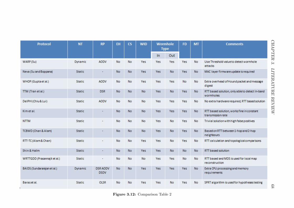
CHAPTER
3.LIT
ERATUREREVIE
W68
Figure 3.12: Comparison Table 2

CHAPTER
3.LIT
ERATUREREVIE
W69
Figure 3.13: Comparison Table 3

CHAPTER 3. LITERATURE REVIEW 70
3.8 Summary
Security of wireless ad hoc networks has always been a hot topic for researchers
since the evolution of wireless ad hoc networks. Due to dynamic nature, resource
constraints (computation power, memory, battery) and shared medium, wireless ad
hoc networks are more vulnerable to different types of security threats. Wormhole
attacks is one of the severe attack which is easy to implement and really hard to
detect.
In this chapter, we briefly discuss about different types of existing solutions
to detect wormhole attacks in wireless ad hoc networks. These solutions can be
categorised in the following categories:
• Hardware/Software based Solutions
• Statistical/Graph Analysis based Solutions
• Challenge/Response based Solutions
• Round Trip Time (RTT) based Solutions
• Intrusion Detection based Solutions
We discuss existing solution from all these categories including their working
process, algorithms involved, network structure and requirement of extra hard-
ware/software. We also discuss whether these solutions considered multirate trans-
mission or not and it can be clearly seen from Figures 3.11, 3.12 and 3.13 that none
of the existing solutions considered multirate transmission. Multirate transmission
is very important factor in real time wireless ad hoc networks and it effects the
detection rate of wormhole attack especially in round trip time (RTT) calculation
based solutions.
In the next chapter, we present our first security protocol “Multirate DSR”
against wormhole attacks in multirate mobile ad hoc networks which is published
in Elsevier Journal of Network and Computer Applications (JNCA) in 2013.

Chapter 4
Multirate DSR
4.1 Introduction
In this Chapter, we present a security enhancement to Dynamic Source Routing
(DSR) [JMB01] protocol, called as Multirate DSR (M-DSR) [QRMS13] against
wormhole attacks for mobile ad hoc networks in multirate transmission. This mech-
anism relies on calculation of round trip time (RTT) and as we already mentioned
in the “Background” chapter that consideration of multirate transmission can really
effect the detection rate for the solutions based upon RTT calculation. Therefore,
it is important to consider the case of multirate transmission which is a reality in
mobile ad hoc networks. We also consider the processing and queuing delays of each
participating node in the calculation of RTTs between the neighbours.
The main differences between our protocol and other existing protocols [THL+07]
and [Als11] is the consideration of multirate transmission and processing/queuing
delays. The overwhelming majority of wireless protocols support different trans-
mission rates at the physical layer, it is not possible to detect a wormhole attack
correctly in a wireless environment using algorithms defined in [THL+07] and [Als11]
as they assume the transmission rate between nodes is constant. If links are faster or
slower then the RTT between those nodes will be considerably different, therefore, it
is hard to say whether this difference in RTT is because of wormhole or transmission
rate.
We compared our proposed M-DSR with the existing security solution proposed
in [THL+07]. As authors in this solution used DSR as a routing protocol and also
used round trip time calculation based solution to detect wormhole attacks in mobile
ad hoc networks. They considered the constant transmission rate between the nodes.
In this chapter, we first discuss how DSR routing protocol works and then discuss
the solution proposed in [THL+07]. We also provide two test cases that show that
not taking multirate transmission into consideration results in miss identifying a
wormhole attack in [THL+07].
We further discuss about our proposed protocol including system assumptions,
notation, network attack model and its working in mutlirate transmission environ-
ment. We also present the security comparison of our protocol with the [THL+07].
In the end, we discuss about performance of our protocol with the help of simulation
results.
71

CHAPTER 4. MULTIRATE DSR 72
4.2 Background
In this Section, we discuss about an existing Transmission Time based Mechanism
(TTM) [THL+07] to detect wormhole attacks and working of DSR [JMB01], which
is the closest work to the one presented in this Chapter.
4.2.1 DSR
Dynamic source routing (DSR) protocol [JMB01], is an on-demand routing protocol
based on the concept of source routing, which means the initiator knows the complete
hop-by-hop route to the destination. This specific feature brings efficiency, but also
results in the scaling of routing message overhead. To perform DSR, each node is
required to maintain a route cache which contains the topology information of the
network. The route cache is consistently updated to reflect the current status of the
network.
Similar to AODV, DSR also consists of two major steps: route discovery and
route maintenance, as shown in Figure 4.1. When a source node originates a route
request packet addressed to a certain destination, the initiator first checks its route
cache for the route information. If there exists an active route towards the desti-
nation, that route is used. Otherwise, the node generates a route request packet
(RREQ) which consists of a data structure called route record listing the IP ad-
dresses of all the intermediate nodes. This RREQ packet is broadcasted to all the
neighbours and the receiving node has two choices.
1. If it is not the target node of this route discovery, it appends its own address
in the route record of RREQ packet and forwards it to its neighbours as a
local broadcast packet.
2. If it is the target node, it returns a RREP packet to the source along with a
copy of accumulated route record.
This process continues until the RREQ packet reaches the destination and the
original packet is not changed except the RREQ data length field which is a number
during the transmission. The resulting route is found in the route record.
The data structure of RREQ packet consists of two fields: IP fields and route
request fields. IP fields contains source node address, destination node address and
hop count limit. Route request fields contains option type, option data length,
identification, target address, and route record. When a RREQ packet is received,
the option data length fields is increased by 4 bytes and the node’s IP address will
be appended to the end of the route record. Other fields remain unchanged during
the route discovery process.

CHAPTER 4. MULTIRATE DSR 73
Figure 4.1: Route Discovery in DSR Protocol

CHAPTER 4. MULTIRATE DSR 74
In replying the RREQ packet, the target node generates a RREP packet and
sends it back to the source in following two ways. It can simply reverse the sequence
of hops in the route record and use it as the source route on the RREP packet.
Otherwise, it checks its own route cache for a route back to the source and if no
such route exists then the destination node initiates a Route Request back to the
source.
During transmission, each node participating in the route is liable for confirm-
ing that data can flow from that node to the next hop. Since periodic routing
advertisement is not available, nodes use the acknowledgement (ACK) to provide
confirmation that a link is capable of carrying data. The ack can be required by a
node. If the ack request has been retransmitted for the maximum number of times
without being replied, the sender should treat this link as “broken”. This link should
be removed from its route cache and should broadcast RERR packet to all nodes
that has sent a packet routed through that link since an ack was last received.
4.2.2 TTM
In [THL+07], Round Trip Time RTT is calculated between two successive nodes
through out the route. The RTT can be calculated by subtracting the RREQ
forwarding time from the RREP receiving time. When the sender generates the
RREQ, it records the sending time. When the node receives the RREQ, it processes
the RREQ and then rebroadcasts it and further, records its sending time as well,
and so on until the RREQ reaches the target destination. Each node participating
in the route receives the RREP generated by destination later on. Thus, every
participating node records the RREP receiving time. Then, each node calculates
its RTT with the destination and appends it to the extensional part in the RREP
which is already created by the destination. When the source node gets the RREP,
it triggers the detecting process to check if the established route is valid or not. The
source node will calculate RTTs between every two successive nodes along the path
based on RTT values in the extensional part of RREP. The authors believed that
if the difference between the RTTs of successive nodes is higher than the threshold
(which they assumed 45s based upon simulation results) value then there is
a wormhole.
Figure 4.2 shows the complete time-line, of how the RREQ travels through all
the nodes, as well as the RREP in the reverse direction. In order to calculate the
RTT, each node records the RREQ forwarding time TNREQ and the RREP receiving
time TNREP , and calculates the RTT between destination and itself. All these
calculated results forwarded to source S with RREP packet, which was generated
by the destination. Finally, the source S calculates the RTT between each two

CHAPTER 4. MULTIRATE DSR 75
Figure 4.2: Time of RREQ and RREP packets
successive nodes. According to Figure 4.2, we obtain four RTT values. The first
value is RTTS,A, the second value is RTTA,B, the third value is RTTB,C , and the
last value is RTTC,D.
The authors also mentioned about the processing time required at each node
which can effect the value of RTT and they proposed a mechanism that instead of
calculating the RTT between two nodes by measuring once, it is measured several
times, say k times, afterwards to calculate the average value of RTT. The authors
considered that this average RTT value gives better results in detection of wormhole
but in actual it does not really work because of difference in transmission time due
to congestion in the network at different times and also difference in processing time
at different time intervals.
The following are the possible threats which can effect the performance of TTM:
1. In TTM, the authors only considered single or fixed rate transmission whereas
in wireless networks, the transmission rate can vary from one point to other
depending upon the capacity of node and the wireless conditions. In fact, we
will show through an example how TTM wrongly identifies wormholes due
to different rates of transmissions on the wireless link. Therefore, it is really
important to provide a solution for multirate transmission.

CHAPTER 4. MULTIRATE DSR 76
2. The second disadvantage in TTM is the longer RTT without the presence of
a wormhole. This longer RTT may be due to processing or queuing delay at
any participating node, which is not considered by TTM. In TTM, authors
calculate the RTT several times to obtain average value and consider it as an
accurate value. But in reality it is hard to get accurate values by calculating
the average because there is a need to reduce the number of route requests.
3. The third disadvantage in TTM is that each node has the right to record the
forwarding time of RREQ, and the receiving time of RREP as well, we may
think malicious nodes will record fake times, unlike the time they use in the
transmission. By doing this the source may not be able to detect the wormhole
link and may not be able to recognize that the network is under an attack.
4. The fourth disadvantage that makes the TTM mechanism inefficient to detect
and locate the exposed wormhole attack, is the ability of the malicious nodes
to delay forwarding both the RREQ and the RREP packets. By doing this,
the source will not be able to pinpoint the wormhole link and the source will
have more than one RTTs values which are larger than the average.
5. Another possible threat in TTM is that malicious nodes can change the RTTs
forwarded by neighbouring nodes because all the RTTs attached with RREP
packet are in normal text. Hence, malicious nodes can easily change these
value to distract the source.
6. TTM is also not secure against wormholes created by packet relay and high
power transmission.
In our protocol proposed in this Chapter, we consider all these threats and it
secures DSR against wormhole attacks in multirate ad hoc networks.
4.3 Proposed Protocol
In this section, we propose a secure DSR protocol against Wormhole attacks in ad
hoc networks which support multirate speeds at their physical layer. In the following
sub sections, we present the notations used in our protocol and system assumptions.
4.3.1 Notations
The notations used in our proposed protocol are summarised in Table 4.1.

CHAPTER 4. MULTIRATE DSR 77
TNRREQRRoute Request receiving time of Node N
TNRREQFRoute Request forwarding time of Node N (noted by neighbours)
RREQSN RREQ packet size at specific node N
TNRREPRRoute Reply receiving time of Node N
TNRREPFRoute Reply forwarding time of Node N
RREPSN RREP packet size at specific node N
RTTNiNj Round Trip Time between nodes Ni and Nj
PTNi Processing time at node Ni
c Speed of light (3 ∗ 108m/s)
d Distance between two nodes
R Maximum range of wireless node (300m)
PD Propagation delay equal to 0.001ms
µ µ is equal to 2ms (limit for RTTs between participating nodes)
Table 4.1: Notations
4.3.2 System Assumptions and Definitions
We consider an ad hoc network consisting of N nodes and are communicating over
a shared wireless medium. Links between nodes are assumed to be bidirectional, i.e.
given a link L(A,B) between nodes A and B in an ad hoc network there exists the
link L(B,A).
We use a directed graph G(N,E) to model an ad hoc network where N is a
finite set of nodes and E is a finite set of bi-directional wireless radio link between
the nodes. Each node NiεN has unique ID (IP address) and moves randomly. Each
mesh node Ni has transmission radius R, according to wireless transmission mode.
Nj is the neighbour of Ni, if node Nj is in the transmission range R of node Ni and
there is a bi-directional wireless link E(i, j) and E(j, i) between the two nodes, as
assumed earlier. We assume that M is a finite set of malicious nodes present in the
network to create wormhole attack whereas M must be greater than 1 and less than
(N − 1).
We use dynamic source routing (DSR) protocol as the routing protocol over
the IEEE 802.11g medium access control protocol. All the nodes in the network
are in promiscuous mode because in dynamic source routing environment, each
node examines every packet it receives. As the node examines the addresses in
each packet, it learns where other nodes are located relative to the node examining
packets. Due to this, nodes do not need to transmit periodic routing advertisements,
such as Routing Information Protocol (RIP) transmissions that are used to inform
other nodes about the state of network.
IEEE 802.11g supports bandwidth up to a maximum of 54Mbps and approxi-
mately 22Mbps on average, and it operates in the 2.4Ghz ISM band. Importantly
and of relevance to our protocols, IEEE 802.11g supports rates at 6, 9, 12, 18, 24, 36,
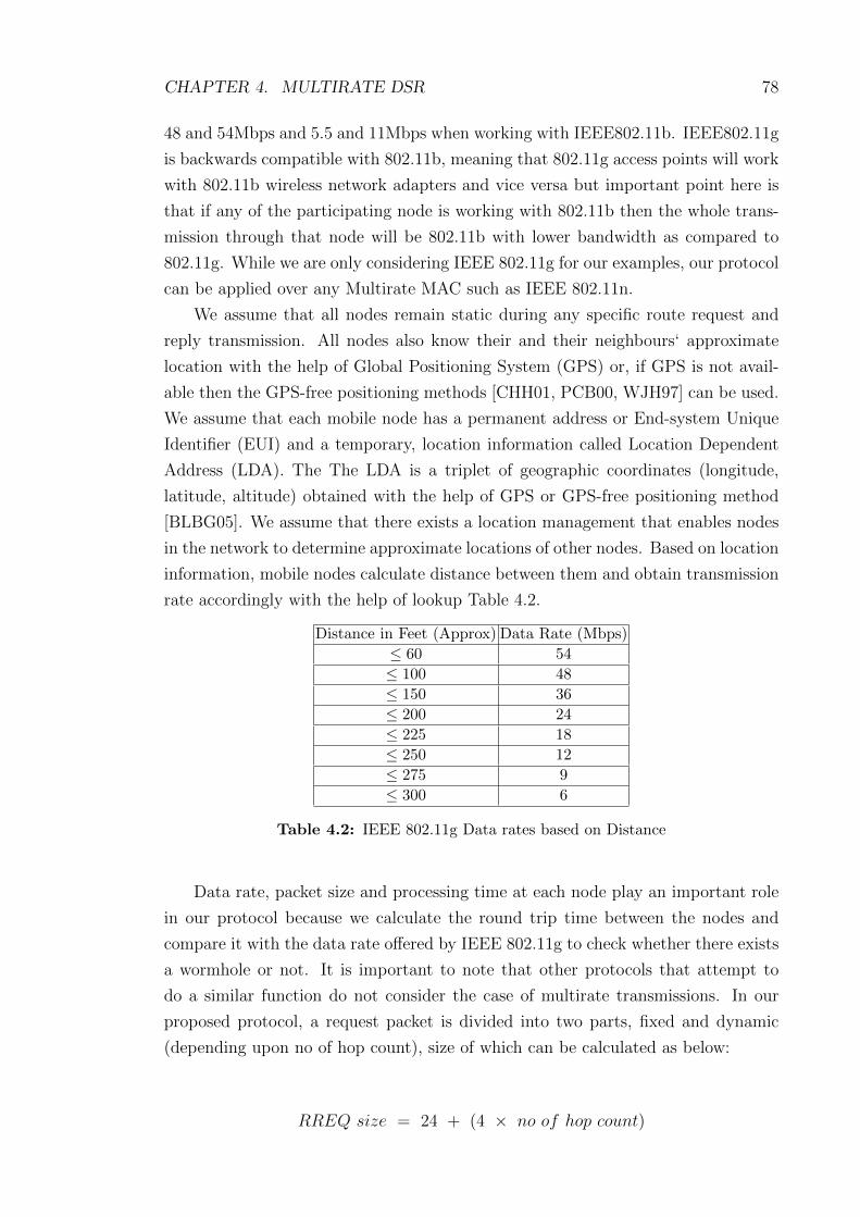
CHAPTER 4. MULTIRATE DSR 78
48 and 54Mbps and 5.5 and 11Mbps when working with IEEE802.11b. IEEE802.11g
is backwards compatible with 802.11b, meaning that 802.11g access points will work
with 802.11b wireless network adapters and vice versa but important point here is
that if any of the participating node is working with 802.11b then the whole trans-
mission through that node will be 802.11b with lower bandwidth as compared to
802.11g. While we are only considering IEEE 802.11g for our examples, our protocol
can be applied over any Multirate MAC such as IEEE 802.11n.
We assume that all nodes remain static during any specific route request and
reply transmission. All nodes also know their and their neighbours‘ approximate
location with the help of Global Positioning System (GPS) or, if GPS is not avail-
able then the GPS-free positioning methods [CHH01, PCB00, WJH97] can be used.
We assume that each mobile node has a permanent address or End-system Unique
Identifier (EUI) and a temporary, location information called Location Dependent
Address (LDA). The The LDA is a triplet of geographic coordinates (longitude,
latitude, altitude) obtained with the help of GPS or GPS-free positioning method
[BLBG05]. We assume that there exists a location management that enables nodes
in the network to determine approximate locations of other nodes. Based on location
information, mobile nodes calculate distance between them and obtain transmission
rate accordingly with the help of lookup Table 4.2.
Distance in Feet (Approx) Data Rate (Mbps)
≤ 60 54
≤ 100 48
≤ 150 36
≤ 200 24
≤ 225 18
≤ 250 12
≤ 275 9
≤ 300 6
Table 4.2: IEEE 802.11g Data rates based on Distance
Data rate, packet size and processing time at each node play an important role
in our protocol because we calculate the round trip time between the nodes and
compare it with the data rate offered by IEEE 802.11g to check whether there exists
a wormhole or not. It is important to note that other protocols that attempt to
do a similar function do not consider the case of multirate transmissions. In our
proposed protocol, a request packet is divided into two parts, fixed and dynamic
(depending upon no of hop count), size of which can be calculated as below:
RREQ size = 24 + (4 × no of hop count)

CHAPTER 4. MULTIRATE DSR 79
for example if the hop count = 4 then RREQ size = 24 + 16 = 40 bytes
RREP size = 24 + (4 × no of hop count) + (18 × no of hop count)
whereas 18 bytes are used to carry the request packet receive/forward, reply
packet receive/forward time, request packet size and reply packet size at each node
(4 bytes to store each time stamp and 1 byte to store packet size in bytes).
In our proposed protocol, the source node calculates the round trip time between
intermediate nodes depending upon the times received in the reply packet and cal-
culates the processing time (if required) and then compares it with the existing data
rate to detect the presence of wormhole attack which is discussed in a later section.
In our protocol, µ is a threshold value which is used to compare the difference
between expected and measured values of RTT. The difference between expected
and measured RTTs should ideally be zero but in case of lower or higher values
than µ indicate the detection of a wormhole in our protocol. We assumed µ equal to
2ms considering the factors involved in real time environment like congestion etc.
4.3.3 Protocol Run
In our proposed protocol, we are calculating the RTTs between the participating
nodes but the most important thing we are considering the case of multirate trans-
mission between them. In our mechanism, during the establishment of a route
between source S and destination D, the source is responsible for calculating RTTs
between all the intermediate nodes and processing time at each node whereas all
participating nodes including the destination are responsible to forward their times-
tamps TNRREQR, TNRREQF
, TNRREPRand TNRREPF
to the source along with the
route reply packet. As we already assumed that all the nodes are working in promis-
cuous mode, therefore, neighbouring nodes can monitor and note down the time
when their next hop neighbour forwards the same request packet. This is another
important difference in our protocol that the request forward time of each node is
monitored/noted by the neighbouring node so there are less chances that malicious
node alter request forward time to create illusion that delay is because of processing
or queueing. After the calculation of RRTs between all nodes, the source compares
RTTs and identifies a wormhole (if it exits) based on a threshold function. The fact
that the expected RTT of two fake neighbours or two node wormhole tunnel will be
considerably much higher or much lower than the measured RTT.
In DSR, when a source node forwards a RREQ to find out the route for the
destination, it receives a RREP from the destination after some time through the

CHAPTER 4. MULTIRATE DSR 80
help of intermediate nodes. Therefore, RTT is the time between forwarding the
RREQ packet & receiving the corresponding RREP packet. Each node taking part
in the route can also overhear when the neighbouring node forwards the same re-
quest packet after processing. Each node along the route stores the time when
it receives RREQ & the time when it receives RREP, whereas neighbouring node
stores the time when the same RREQ packet is forwarded by the next hop node.
In [THL+07], each participating node calculates the RTT and forwards it to the
source with RREP packet, whereas in our protocol, all participating nodes forward
their request receiving time, reply receiving time, reply forwarding time and request
forwarding time of a neighbouring node to the source with RREP packet. Now at
the source node all calculations are being done which is more secure as compared
to mechanism discussed in [THL+07] because in our protocol, the source has all the
information and can compare the request receiving and request forwarding times of
specific node to calculate processing time involved at that node. The source then
selects the best possible route and starts communication with the destination (usu-
ally the shortest path). The source also broadcasts a message to all nodes about the
malicious nodes (if any exist).
4.3.3.1 Calculation of RTT and Processing Time
In this section, we discuss the calculation procedure of RTT between neighbouring
nodes and processing time (PT) at each participating node. Let us assume that node
S wants to communicate with node D and S does not have routing information for
D in its routing table/cache as shown in Figure 5.4. To find out the best possible
route, S broadcasts a route request RREQ with some alteration according to our
protocol as mentioned below.
As shown in Figure 5.4, there are two possible routes available from source S
to destination D. One is (S → A → B → C → E → D) and second route is
(S → A→ F → G→ D). Source node S receives replies from both routes with all
the corresponding values as mentioned below.
1. S → ∗ : RREQ,D, TS, SR{S}
2. A→ ∗ : RREQ,D, TS, SR{S,A}
3. B → ∗ : RREQ,D, TS, SR{S,A,B}
4. F → ∗ : RREQ,D, TS, SR{S,A, F}
5. C → ∗ : RREQ,D, TS, SR{S,A,B,C}
6. G→ ∗ : RREQ,D, TS, SR{S,A, F,G}

CHAPTER 4. MULTIRATE DSR 81
Figure 4.3: Route Request in the absence of Wormhole Attack
7. E → ∗ : RREQ,D, TS, SR{S,A,B,C,E}
8. D → G : RREP, S, TS, SR{S,A, F,G,D}, TDRREQR, RREQSD,
TDRREPR, TDRREPF
, RREPSD
9. G→ F : RREP, S, TS, SR{S,A, F,G,D}, TDRREQR, TDRREQF
,
RREQSD, TDRREPR, TDRREPF
, RREPSD, TGRREQR, RREQSG,
TGRREPR, TGRREPF
, RREPSG
10. F → A : RREP, S, TS, SR{S,A, F,G,D}, TDRREQR, TDRREQF
,
RREQSD, TDRREPR, TDRREPF
, RREPSD, TGRREQR, RREQSG,
TGRREPR, TGRREPF
, RREPSG, TFRREQR, RREQSF , TFRREPR
,
TFRREPR, RREPSF , TGRREQF
11. A→ S : RREP, S, TS, SR{S,A, F,G,D}, TDRREQR, TDRREQF
,

CHAPTER 4. MULTIRATE DSR 82
RREQSD, TDRREPR, TDRREPF
, RREPSD, TGRREQR, RREQSG,
TGRREPR, TGRREPF
, RREPSG, TFRREQR, RREQSF , TFRREPR
,
TFRREPR, RREPSF , TGRREQF
, TARREQR, RREQSA, TARREPR
,
TARREPF, RREPSA, TFRREQF
Similarly source node S receives the second route reply. Now the source needs to
calculate the RTT and transmission time between the intermediate nodes to detect
the existence of a wormhole attack.
Source S calculates the RTT between participating nodes on the basis of val-
ues received with RREP packet and creates a timing table 5.4 which includes the
following information:
Node TNRREQRTNRREQF
RREQSN TNRREPRTNRREPF
RREPSN RTTND
S TSRREQRTSRREQF
RREQSS TSRREPRTSRREPF
RREPSS TSRREPR− TSRREQF
A TARREQRTARREQF
RREQSA TARREPRTARREPF
RREPSA TARREPR− TARREQF
F TFRREQRTFRREQF
RREQSF TFRREPRTFRREPF
RREPSF TFRREPR− TFRREQF
G TGRREQRTGRREQF
RREQSG TGRREPRTGRREPF
RREPSG TGRREPR− TGRREQF
Table 4.3: RTT between participating nodes and destination
After the RTT calculation of all the participating nodes with the destination,
the source node S calculates the RTT between the intermediate nodes, as shown in
Table 5.5.
RTTSA = RTTSD −RTTAD
RTTAF = RTTAD −RTTFD
RTTFG = RTTFD −RTTGD
Table 4.4: RTT between intermediate nodes
We have considered the case of multirate transmission in our protocol whereas
the state of the art only considered constant data rate which can not detect wormhole
as illustrated in our example in the later section. According to TTM, if there is a
wormhole tunnel involved in the network then the time between the wormhole tunnel
end points is much greater or much smaller as compared to normal nodes, which is
only true when there is constant transmission rate throughout the network (which
is not a practical assumption).
Once the source node has calculated the RTT between neighbouring nodes, the
source has to compare all the actual RTTs with expected RTTs based upon the
transmission rate between the neighbouring nodes to check whether there exists a
wormhole tunnel or not. For this purpose, the source runs an algorithm as shown
below:

CHAPTER 4. MULTIRATE DSR 83
Algorithm 1 Wormhole checking between intermediate nodes.
Assume that N nodes are randomly placed in an ad hoc network and source
calculated the RTTs of all the neighbouring nodes involved in the route.
Calculate PT for RREQ and RREP Packets
Calculate TT for RREQ and RREP Packets
Calculate RTT = (TTNi+ PTNi
+ PD)
Compare actual RTT with expected RTT
if |A(RTTNiNi+1)− E(RTTNiNi+1
)| ≤ |µ| then
NO Wormhole
else
Wormhole Detected between Ni and Ni+1
end if
As shown in the algorithm above, source first calculates the processing time
at each node and expected transmission time based upon packet size and available
bandwidth between two nodes and then compares the actual RTTs with the expected
RTTs of all the participating nodes and if the difference is less than or equal to µ then
the route is considered to be safe, otherwise source flags an alert about wormhole
detected between nodes Ni and Ni+1. To calculate excepted transmission time TT,
the source can use following equation:
TT =PacketSize(bits)
bandwidth(bps)(4.1)
PTRREQNiPTRREPNi
TNiRREQF− TNiRREQR
TNiRREPF− TNiRREPR
Table 4.5: Processing Time Calculations
Now the source has to calculate the processing time while processing RREQ
and RREP packets simultaneously as shown in Table 5.6 of each intermediate node.
As we assumed that our network is in promiscuous mode, therefore, TNRREQFis
monitored and forwarded by the neighbouring node which is considered to be more
secure as malicious node can not change that value.
The source calculates the expected transmission time (TT) of RREQ and RREP
packet using Equation 1. Packet sizes are being forwarded by each node therefore
the source can easily calculate the transmission time for two neighbouring nodes as
mentioned below:

CHAPTER 4. MULTIRATE DSR 84
TTNiNi+1=
Packet Size (in this case its RREQ)
Bandwidth
TTNi+1Ni =Packet Size (in this case its RREP )
Bandwith
Therefore, RTTNiNi+1= TTNiNi+1
+ TTNi+1Ni (4.2)
But in our calculation above RTT between two nodes does not include the
processing time of RREP packet so we have to add processing time and propagation
delay as well in this equation and then the source can compare the expected RTTs
and actual RTTs. The generalized form of the calculation is as follows.
RTT =2N−1∑
i
(TTi + PTi + PD) (4.3)
Hence, RTT =2N−1∑
i
((Packet Size
Bandwidthi
)+ PTi + PD
)(4.4)
Once the source completes all the calculations, the source node can easily de-
tect a wormhole attack by comparing the expected RTT values (calculated based
upon transmission rate between the corresponding nodes and packet size) and ac-
tual RTT values (calculated based upon values received from corresponding nodes).
The source can then avoid malicious nodes and choose the best possible route to
communicate with the destination.
4.3.4 Attack Model
In this section, we consider two different examples to demonstrate how our proposed
protocol works for the detection of a wormhole attack within multirate transmission
and how algorithms that assume constant rate transmission such as TTM [THL+07]
provide inaccurate results. We consider that a wormhole is launched by malicious
nodes.
4.3.4.1 First Example
Let us assume that an ad hoc wireless network is established as shown in Figure 4.4
and node S wants to communicate with nodeD. S does not have routing information
for D in its routing table. DSR is the routing protocol whereas IEEE802.11g is the

CHAPTER 4. MULTIRATE DSR 85
MAC and physical layer protocol with multirate data transmission between the
nodes as mentioned in Figure 4.4. To find out the best possible route, S broadcasts
a route request RREQ with some alteration according to our protocol.
Figure 4.4: Route Request from Source S to Destination D
4.3.4.2 Working of TTM [TTM] - Multirate Transmission Example
In this subsection, we present, how TTM works for multirate transmission to detect
the wormhole attack. The source S broadcasts the route request for the destination
D and all the nodes participating in the route request appends the request packet
by adding TNREQ request time. Once the destination receives the request packet, it
then prepares a reply packet and transmits it back to the same node from which it
received the request. All the participating nodes append their route reply receiving
time as well with the reply packet.
Upon reception of route reply, the source node calculates and creates the RTT
tables as:
Node TNREQ TNREP RTTND
S 0 34 34F 0.5 30.5 30G 3.5 23.5 20H 8.5 15.5 7
Table 4.6: RTTs with destination in TTM
After the calculation of RTT of all the participating nodes with the destination,

CHAPTER 4. MULTIRATE DSR 86
now source node S calculates the RTT between the intermediate nodes, as shown
in Table 4.7.
RTTSF = 4RTTFG = 10RTTGH = 13RTTHD = 7
Table 4.7: RTTs between intermediate nodes in TTM
As shown in Table 4.7, RTTFG and RTTGH are large numbers as compared
to other RTTs. According to TTM, nodes with the larger RTT are malicious and
are part of a wormhole tunnel. Hence nodes G and H are wrongly identified as
malicious. This occurs because there is a transmission rate deferential between the
hops. TTM works if we assume the transmission rate at each node is constant. This
is the main drawback of TTM and motivation for our work as our protocol works
for both constant and multi transmission rate. In next subsection, we present how
our protocol works for this example.
4.3.4.3 Working of Proposed Protocol - Multirate Transmission Exam-
ple
As discussed in the previous section, the source S broadcasts the route request for
the destination D. The next node in the network receives that request packet and
rebroadcasts it to its neighbours after performing necessary processing. All the
neighbouring nodes receive that request packet and rebroadcast it until it reaches
the destination D. Then D prepares a reply packet and forwards it back to the same
route from which it received the request. D replies to all the requests received from
different routes after fulfilling all the requirements mentioned in our protocol. All
the nodes participating in the route forward back the route reply to their next hop
until it reaches the source node S.
Upon reception of route reply, the source node calculates and creates the RTT
tables as:
Node TNRREQRTNRREQF
RREQSN TNRREPRTNRREPF
RREPSN RTTND
S 0 0 28 34 34 112 34
F 0.5 2.5 32 30.5 32.5 94 28
G 3.5 5.5 36 23.5 26.5 76 18
H 8.5 10.5 40 15.5 17.5 58 5
Table 4.8: RTT between participating nodes and destination
After the calculation of RTT of all the participating nodes with the destination,
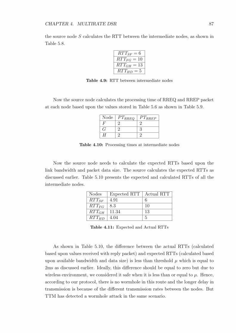
CHAPTER 4. MULTIRATE DSR 87
the source node S calculates the RTT between the intermediate nodes, as shown in
Table 5.8.
RTTSF = 6RTTFG = 10RTTGH = 13RTTHD = 5
Table 4.9: RTT between intermediate nodes
Now the source node calculates the processing time of RREQ and RREP packet
at each node based upon the values stored in Table 5.6 as shown in Table 5.9.
Node PTRREQ PTRREP
F 2 2G 2 3H 2 2
Table 4.10: Processing times at intermediate nodes
Now the source node needs to calculate the expected RTTs based upon the
link bandwidth and packet data size. The source calculates the expected RTTs as
discussed earlier. Table 5.10 presents the expected and calculated RTTs of all the
intermediate nodes.
Nodes Expected RTT Actual RTTRTTSF 4.91 6RTTFG 8.3 10RTTGH 11.34 13RTTHD 4.04 5
Table 4.11: Expected and Actual RTTs
As shown in Table 5.10, the difference between the actual RTTs (calculated
based upon values received with reply packet) and expected RTTs (calculated based
upon available bandwidth and data size) is less than threshold µ which is equal to
2ms as discussed earlier. Ideally, this difference should be equal to zero but due to
wireless environment, we considered it safe when it is less than or equal to µ. Hence,
according to our protocol, there is no wormhole in this route and the longer delay in
transmission is because of the different transmission rates between the nodes. But
TTM has detected a wormhole attack in the same scenario.
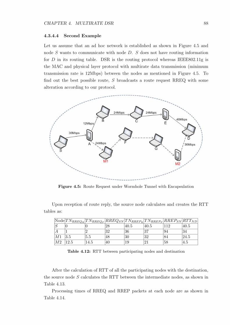
CHAPTER 4. MULTIRATE DSR 88
4.3.4.4 Second Example
Let us assume that an ad hoc network is established as shown in Figure 4.5 and
node S wants to communicate with node D. S does not have routing information
for D in its routing table. DSR is the routing protocol whereas IEEE802.11g is
the MAC and physical layer protocol with multirate data transmission (minimum
transmission rate is 12Mbps) between the nodes as mentioned in Figure 4.5. To
find out the best possible route, S broadcasts a route request RREQ with some
alteration according to our protocol.
Figure 4.5: Route Request under Wormhole Tunnel with Encapsulation
Upon reception of route reply, the source node calculates and creates the RTT
tables as:
Node TNRREQRTNRREQF
RREQSN TNRREPRTNRREPF
RREPSN RTTND
S 0 0 28 40.5 40.5 112 40.5
A 1 2 32 36 37 94 34
M1 3.5 5.5 48 30 32 84 24.5
M2 12.5 14.5 40 19 21 58 4.5
Table 4.12: RTT between participating nodes and destination
After the calculation of RTT of all the participating nodes with the destination,
the source node S calculates the RTT between the intermediate nodes, as shown in
Table 4.13.
Processing times of RREQ and RREP packets at each node are as shown in
Table 4.14.

CHAPTER 4. MULTIRATE DSR 89
RTTSA = 6.5RTTAM1 = 9.5RTTM1M2 = 20RTTM2D = 4.5
Table 4.13: RTT between intermediate nodes
Node PTRREQ PTRREP
A 1 1M1 2 2M2 2 2
Table 4.14: Processing times at intermediate nodes
The source node needs to calculate the expected RTTs based upon the link
bandwidth and the packet data size. The source calculates the expected RTTs as
discussed earlier. Table 4.15 presents the expected and calculated RTTs of all the
intermediate nodes.
Nodes Expected RTT Actual RTTRTTSA 4.889 6.6RTTAM1 7.250 9.5RTTM1M2 13 20RTTM2D 3.722 4.5
Table 4.15: Expected and Actual RTTs
As shown in Table 4.15, the difference between the actual RTT and expected
RTT of node M1 and M2 is much greater than threshold µ. We assumed that the
transmission rate between M1 and M2 is 12Mbps which is our minimum transmis-
sion rate, even then difference is much greater. Hence, according to our protocol,
there is a wormhole tunnel between M1 and M2. Source node broadcasts this in-
formation to all other nodes and discards this route. The source node checks for
alternate routes and after successful checking, it selects the best possible route for
communication with destination.
4.4 Security Analysis
In this section, we present security analysis of our proposed protocol based upon
the different wormhole attack modes as discussed in Section 2.

CHAPTER 4. MULTIRATE DSR 90
4.4.1 Security Against packet encapsulation wormholes
As discussed in earlier sections, our protocol is secure against packet encapsulation
wormhole attacks. In Figure 4.5, M1 and M2 are two malicious nodes and they have
created a wormhole tunnel between them with the help of packet encapsulation.
Therefore, one route between source S and destination D is (S → A → M1 →M2 → D) and the other route is (S → A → B → C → E → D). According to
our protocol, we compare the expected RTT values and actual RTT values to check
both the routes. Therefore, according to our protocol, the source node S discards
route 1 and selects route 2 for communication with the destination and hence, our
protocol is secure against packet encapsulation wormholes.
4.4.2 Security against out-of-band wormholes
Our proposed protocol secures DSR against out-of-band wormhole attacks as well.
As shown in Figure 4.6, Node S sends a route request for node D, whereas M1 and
M2 are malicious nodes having an out-of-band channel between them.
Figure 4.6: Wormhole Tunnel using Out-of-Band Channel
Node M1 tunnels the route request to M2, which is a legitimate neighbour
of D. Node M2 broadcasts the packet to its neighbours, including D. D gets
three route requests (S → M1 → M2 → D), (S → A → B → C → D) and
(S → A→ E → F → G→ C → D).
Once the source node S receives all these three routes replies, it calculates the
RTTs between the consecutive nodes for all three routes and then decides which
route to choose for communication. In case of route 1, the hop count is less when

CHAPTER 4. MULTIRATE DSR 91
compared to other two routes but the difference between expected RTT and actual
RTT of M1 and M2 is considerably smaller than all other neighbouring nodes
because M1 and M2 have high speed wired or wireless link. Our protocol is checking
for all abnormal RTTs whether very high or very low. Therefore, route 1 is not
selected, any other route can be selected based upon time and hop counts.
This type of wormholes can be detected using the assumption of bi-directional
links/channels. Suppose a malicious node say M1, tries to use high power trans-
mission to forward a packet P1 to its final destination, or to cross multiple hops to
introduce itself in the shortest path. But on receiving a reply packet from all possi-
ble routes, the source node calculates the RTTs for all neighbouring nodes. Based
upon the RTT of all the consecutive nodes,a malicious node can be detected easily
and the source does not select the route which contains the malicious node.
4.4.3 Security against Packet Relay wormholes
As in DSR, all nodes participating in active routes have the list of their neighbours,
therefore if a malicious node M1 tries to relay a packet between two non neighbour
nodes A and B and deceives them that they are neighbours. Both nodes detect the
malicious behaviour of M1 since they know that they are not neighbour and they
also calculate the RTT between them. Then this RTT can be compared with the
RTT of two neighbouring nodes to confirm whether there is a wormhole or not.
4.4.4 Security against TTM [THL+07] threats
1. In our protocol, we also considered transmission and processing times to avoid
any wrong detection as we discussed earlier in case of TTM when working with
multirate transmission.
2. Our proposed protocol works in multirate transmission environment as well
which was not covered in the literature. As shown in example, our proposed
protocol identifies that the delay is not because of wormhole whereas it is
because of slow transmission rate between intermediate nodes.
3. In our protocol, each node has to forward the request forwarding and reply
receiving/forwarding time instead of RTT, therefore, the source can compare
all the consecutive nodes’ request and reply timings to make the decision about
correctness of timings. This feature also helps us in taking care of the queuing
delay involved at each node. Hence if a node stores corrupted data, it will be
detected by the source.
4. According to our protocol, if any of the malicious node delays the RREQ or

CHAPTER 4. MULTIRATE DSR 92
RREP packet that can be detectable by the source based of transmission time
calculation and comparison of RTT of consecutive nodes.
4.5 Performance Analysis
In this section, we present performance analysis of our proposed protocol in com-
parison with TTM. As we mentioned earlier, in our proposed protocol, there is no
requirement of any complex calculation or statistical analysis. Our protocol cal-
culates RTTs based upon the values received through RREQ and RREP packets
during route discovery process. According to our protocol, nodes require some ad-
ditional memory to store RTTs of corresponding nodes and some extra processing
time required to perform linear calculation to find out RTT between corresponding
nodes and it depends upon the number of hops participating in that route. In other
existing solutions, complex calculations or statistical analysis is required which is
time consuming and also require extra memory.
If we compare performance in terms of memory and processing of our protocol
with existing DSR protocol, there is not much difference because in our protocol,
every participating node needs to add 18 bytes of extra data with RREP packet
and all the calculations to find out RTTs is being done at the source. Therefore,
our protocol does not create much difference as compared to DSR but in the end by
using our protocol, we are able to safeguard our routing protocol against wormhole
attacks.
Another important performance metric of our protocol is that we focused on
multirate transmission problem which is not covered by TTM. It is clearly shown
in our examples that without considering multirate transmission, wormhole attacks
may be detected wrongly or may not be detected properly.
We present some simulation results to compare our proposed protocol with the
existing solution TTM in terms of detection rate and also present the detection rate
of our protocol in different background traffic scenarios (light, medium and heavy
background traffic). We also compare the overhead between the two protocols and
present the results in the following subsection.
4.5.1 Simulation Scenario
In this section, we define simulation environment in detail including all input pa-
rameters. We distribute the nodes randomly over a square field with a fixed average
node density. The simulation parameters are summarized in Table 4.16.
In our simulations, we randomly selected source and destination pairs and as-
signed different bandwidths between the node pairs to highlight the effect of mul-

CHAPTER 4. MULTIRATE DSR 93
Terrain Area 1500m X 1500m
Number of Nodes 100
Tx Range(r) 150m
Channel Bandwidth 2Mbps − 54Mbps
Routing Protocol DSR
Network Topology IEEE802.11g
Addressing Mode IPV 4
Packet Size 512Bytes
Tunnel size 2, 4, 6, 8, 10
Table 4.16: Simulation Inputs
tirate environment. We randomly placed the malicious nodes in the network. We
run more than 100 simulations with different data rates between node pairs and for
different number of nodes as mentioned in Table 6.7. We run simulations for differ-
ent scenarios like different transmission rates between the node pairs. This helps us
in selecting the threshold value for comparison between expected and actual RTT
values for multirate transmission scenario. For our simulations, we consider 2ms as
a threshold value due to the fact that it gives more than 80% detection rate.
4.5.2 Results and Discussions
To further investigate the performance of our protocol, we run simulations in dif-
ferent scenarios with different network sizes. To check the accuracy of our protocol,
we initially consider an ideal case in which we avoid processing and queueing delay
of all nodes participating in the routing and this gives us 100% detection rate in
both type of wormhole attacks (Inbound and out-of-band). This ideal scenario also
indicates that the performance of our protocol is not effected by number of nodes.
To investigate the performance of our protocol, we first run simulations for in-
bound wormhole attacks with different tunnel lengths as mentioned in Table 6.7.
We consider processing and queueing delay involved at each node participating in
the routing. Figure 4.7 shows the detection rate of our protocol for in-band and
out-of-band wormhole attacks and detection rate is around 80%. There is slight
decrease in detection rate with the passage of time but this is because of processing
and queueing delays which is due to increase in network traffic. We run these sim-
ulations 100 times for each type of wormhole attack and then calculated average of
detection rate and also present false positives in our simulations.
We further investigate the performance of our protocol in different background
traffic scenarios. We consider three types of background traffic light, medium and
heavy. In light background traffic we consider 30% of nodes communicating through-

CHAPTER 4. MULTIRATE DSR 94
Figure 4.7: Wormhole Detection Rate
out the simulation, whereas in medium background traffic, we consider 50% of
nodes communicating and in heavy traffic, we consider 80% of nodes communi-
cating throughout the simulation. We run these simulation for both in-band and
out-of-band wormhole attacks. For in-band attacks, we consider the tunnel length
equal to 4 and run the simulations for the same network sizes as mentioned in Ta-
ble 6.7. As we have already considered the processing and queueing delays in our
protocol, we get around 80% detection rate for light and medium background traffic
whereas for heavy traffic it is still above 70%, as shown in Figure 4.8. This small
decrease in detection rate for heavy traffic is because of increase in queueing delays.
We calculate average of detection rate and also present error bars to indicate the
variance in detection rate.
We also investigate the transmission overhead of our proposed protocol with
the existing protocol (TTM). We run these simulation for both in-band and out-
of-band wormhole attacks. We first run simulations for inbound wormhole attacks
with different tunnel lengths as mentioned in Table 6.7. We consider processing and
queueing delay involved at each node participating in the routing. We use same
simulation parameters for the TTM to find out the overall overhead. Figure 4.9
shows the overhead of our protocol and TTM. We run these simulations 100 times
for different network size (based on number of nodes) and then calculated average of
overhead for both the protocols. Overhead gradually increased with the increased
number of nodes in the network but our protocol overhead is less than the TTM.

CHAPTER 4. MULTIRATE DSR 95
Figure 4.8: Wormhole Detection rate in different background traffic
4.6 Summary
In this chapter, we discussed anomalies of TTM [THL+07] in multirate transmis-
sion and then proposed a solution which secures DSR against wormhole (Inbound
and out-of-band) attacks in multirate transmission. Our proposed solution is based
on round trip time (RTT) calculation which is quite popular mechanism to detect
wormhole attacks in mobile ad hoc networks. These types of solutions do not need
any special hardware or complex statistical analysis and are simple to implement.
All of the existing solutions based on RTT calculations discussed in literature
review chapter, consider the constant data transmission rate which is not right in
the case of wireless environment. In our proposed solution, we considered DSR as
routing protocol and considered multirate transmission environment which is a very
important factor. We provided two different examples, one with fixed rate transmis-
sion and other with multirate transmission to explain the difference of our protocol
with [THL+07].
Our simulation results show that our proposed solution gives around 80% de-
tection rate for both In-band and out-of-band wormhole attacks with false positives
around 20%. Furthermore, it also identify and isolate the malicious nodes to im-
prove the performance of routing protocol.

CHAPTER 4. MULTIRATE DSR 96
Figure 4.9: Transmission overhead M-DSR and TTM
In the next chapter, we present our second security protocol “Multirate DelPHI”
against wormhole attacks in multirate mobile ad hoc networks which is submitted
in Elsevier Journal of Computer Communications and currently is under review.

Chapter 5
Multirate DelPHI
5.1 Introduction
In this Chapter, we propose an extension to DelPHI (Delay Per Hop Indication)
[CL06], M-DelPHI that adapts it to the multirate 802.11 wireless channel. Our
protocol also caters for processing delays at each participating node to achieve better
detection rate as compared to the original protocol. We propose three fundamental
extensions, which are as under:
1. Multirate calculation
2. Processing delay calculations
3. Neighbour monitoring
In multirate calculations, we consider the case of multirate transmission between
the nodes while calculating round trip time (RTT) between them and present how
it affects the detection rate. This consideration results in better detection rate and
zero false positives as presented in simulation results in later sections. We also con-
sider the processing delays at different participating nodes and present their effects
in wormhole detection especially using the technique of RTT calculation. Accord-
ing to our protocol, all the nodes in the network are in promiscuous mode and
monitor their neighbours and forwards the timestamps of their route reply packets
as discussed in detail in later sections. We also provide 2 test cases that demon-
strate working of DelPHI and our extension (M-DelPHI) in multirate transmission
along with simulation results. We show that M-DelPHI performs exceptionally well
resulting in above 90% wormhole detection rate against in-band and out-of-band
wormholes under the specified test conditions.
We further discuss about our proposed protocol including system assumptions,
notation, network attack model and its working in mutlirate transmission environ-
ment. We also present the security comparison of our protocol with the DelPHI. In
the end, we discuss about performance of our protocol with the help of simulation
results.
97

CHAPTER 5. MULTIRATE DELPHI 98
5.2 Background
In this Section, we discuss about working of DelPHI [CL06] and AODV [PBRD03]
protocol in detail and also present how DelPHI performs in a multirate transmission
environment.
5.2.1 AODV
Ad hoc On Demand Distance Vector (AODV) is one of the most popular on demand
routing protocol, in which routes between the source and the destination are iden-
tified on requirement basis only, which results in less overheads in terms of memory
and power. In AODV routing protocol, a destination sequence number is used which
is generated by the destination itself for each separate route entry. This sequence
number ensures that there is no loop in the route and if two similar routes exist, then
the node chooses the one with the highest sequence number. For route discovery
and maintenance in AODV routing protocol, Route Request (RREQ), Route Reply
(RREP) and Route Error (RERR) packets are used.
The routing operations of AODV protocol mainly consist of two steps: route dis-
covery and route maintenance. In Figure 5.1, Route discovery is performed through
broadcasting RREQ messages. When a source node wishes to establish a route to
a destination for which it does not already have a route, it broadcasts a route re-
quest (RREQ) packet across the network. RREQ carries Source ID, Destination ID,
Source Sequence Number, Destination Sequence Number and a Broadcast ID. When
an intermediate node receives a RREQ, it sends a route reply (RREP) if it is either
the destination or if it has a route to the destination with corresponding sequence
number greater than or equal to that contained in the RREQ. The intermediate
node also stores the previous node information in order to forward the data packet
to this next node towards the destination.
When the RREQ packet reaches the destination, a RREP packet is generated
by the destination in a response to the RREQ packet. The RREP is then sent back
to the source in order to share information about the route. If an intermediate node
has an active route towards the destination, it can reply the RREQ packet with a
RREP packet, which is called Gratuitous Route Reply. The intermediate node also
sends an RREP packet to the destination node.
Whenever there is a link break in the routing path, the RERR message will be
broadcasted by the link break identifying node to the neighbour nodes to update
or delete the routes through that node and the source initiates another RREQ
broadcast to find fresh routes to the destination. AODV keeps the track of following
information for a specific route:

CHAPTER 5. MULTIRATE DELPHI 99
Figure 5.1: Route Discovery in AODV Protocol

CHAPTER 5. MULTIRATE DELPHI 100
• Destination IP address
• Destination sequence number
• Hop count
• Next hop
• Lifetime
5.2.2 DelPHI
DelPHI was proposed to secure AODV protocol against wormhole attacks in mobile
ad hoc networks and has been widely cited in recent research. A major drawback of
DelPHI is that it assumes that the end-to-end multihop connection has a constant
average bit rate and works well under such assumptions to secure AODV routing
protocol.
DelPHI is an extension to AODV but unlike AODV, every node has to forward
the DREQ packet towards the destination whether or not a record is already present
in the routing table, until the packet reaches the destination. In DelPHI, the des-
tination replies to every DREQ packet received whereas in AODV, the destination
only replies to the first RREQ received. The data collection procedure (DREQ &
DREP procedure) is repeated 3 times in order to enhance reliability of data whereas,
in AODV, RREQ is forwarded only once. By repeating the same request 3 times,
DelPHI adds significant overhead in terms of processing and bandwidth.
The authors divided DelPHI in two phases; A Data collection phase and a Delay
calculation phase. In the Data collection phase, they measured the end to end RTT
and the number of hops between sources and destinations. They did this using
DREQ and DREP packets. In the second phase, they calculated the Delay per Hop
value of the route as shown in Equation 1.
DPH =RTT
2 × h (hop count)(5.1)
whereas, h is the hop count.
The authors run simulations for different scenarios with or without background
traffic, with variable wormhole tunnel lengths and for different values of threshold
(1, 2, 3, 5)ms. The threshold is used for comparison between normal RTT values and
a RTT under wormhole attack. Based upon the simulation results, they finally set
the threshold value equal to 3ms which gives a detection rate above 80%.
To enhance the credibility of the data collected, DelPHI repeats the same pro-
cedure three times and they considered the possibility of different hop counts for the

CHAPTER 5. MULTIRATE DELPHI 101
same neighbour. In this scenario, they considered the delay per hop of the shortest
path for analysis.
5.2.3 DelPHI in a Multirate Environment
This section considers two different examples of DelPHI in a multirate transmission
environment.
5.2.3.1 False positive scenario for DelPHI
We assume that an ad hoc network is setup as shown in Figure 5.2 and node S intends
to start communication with node D. S does not have any routing information for
D in its routing table. In Figure 5.2, we assume that IEEE 802.11g WiFi network
is being used, although 802.11n or any other multirate can be assumed for this
example.
Figure 5.2: Route Request from S to D
The source S broadcasts the route request DREQ for the destination D. In
DREQ, the previous hop field contains the source ID, the hop count is equal to 1
and a timestamp. These fields are modified by the intermediate nodes whereas, the
timestamp remains the same throughout the route. The source node safeguards the
integrity of the timestamp by signing it (alternate method such as in [ZSR08] can
also be used for such a step). All the nodes participating in the route create a reverse
path to the source and increases hop count by 1 and then rebroadcasts it until it
reaches the destination. Once the destination receives the DREQ, it then prepares
a DREP and unicasts it to the source through the reverse path. In a similar way to
the request procedure, all the participating nodes put their ID into the previous hop

CHAPTER 5. MULTIRATE DELPHI 102
and increase the hop count by 1 upon receiving the DREP packet. In DelPHI, the
destination replies to all DREQ packets received unlike AODV which only replies
to the first RREQ received. Hence the source receives a number of DREP packets
and calculates different delay per hop (DPH) values for each DREP received.
The source node at time ts broadcasts the DREQ packet and receives the
DREP packet at time ti then the round trip time (RTT) of the path is given
by RTT = ti− ts. If the hop count in the DREP packet from node i is hi, then the
delay per hop value (DPH) of the path is given by
DPHi =RTTi2hi
=ti − ts
2hi(5.2)
The source calculates the DPH value 3 times according to 3 different DREQ
and DREP packets. To identify a wormhole attack, they arrange the DPH values
in descending order and check whether there is a large difference between 2 adjacent
values or not. If DPHi is greater than the next DPH value by a Threshold T , then
the path through node i and all other paths with DPH values greater than DPHi
are treated as under wormhole attack. In DelPHI, the authors considered that in
the case of a smaller number of hops, the RTT should be smaller in normal cases
but in the case of a wormhole tunnel it is always higher. While this may be ok
for a fixed transmission rate assumption, this is not always the case for multirate
transmission.
The Source receives three routes replies from destination which are:
1. R1 = S → I → J → D
2. R2 = S → F → G→ H → D
3. R3 = S → A→ B → C → E → D
The Source receives different values for all three routes and calculates RTTs
and DPHs with the help of Equation 2, which are shown in Table 5.1
Route ts ti HopCount RTT DPHR1 0 27 3 27 4.5R2 0 23 4 23 2.87R3 0 26 5 26 2.6
Table 5.1: RTTs and DPH calculation in DelPHI Protocol
To check the reliability of data, the source node repeats the route request pro-
cedure two more times and then calculates the average. Then after calculating the
average, the source node identifies which route is under wormhole attack and which
is a safe route based upon DPH values. According to Table 5.1, the source node

CHAPTER 5. MULTIRATE DELPHI 103
considers route R1 under wormhole and other two routes R2 and R3 as safe routes
because the DPH of R1 is higher than threshold value (which is 3ms). But in
reality all three routes are safe and the DPH of route R1 is higher because of low
bandwidth between the participating nodes. This simple case study demonstrates
that the DelPHI generates false detection of a wormhole attack when link speeds
are different between nodes.
5.2.3.2 Failure to detect a wormhole
In this section, we introduce another case study that shows that DelPHI will fail
to detect an attack when one is present. We assume that an ad hoc network is
setup as shown in Figure 5.3 and node S wants to start communication with node
D without any prior routing information. IEEE802.11g is the MAC and physical
layer protocol with multirate data transmission as shown in Figure 5.3. M1 and
M2 are two malicious nodes connected through a high speed direct link. This high
speed link could be wireless or wired.
Figure 5.3: Route Request from Source to Destination
According to DelPHI, the source S broadcasts DREQ packet to find out the
possible routes to the destination D. As mentioned earlier, upon reception of a
DREP packet by the source node, S calculates the RTTs and DPHs of each
possible route accordingly. The source node receives three route replies from the
destination as shown below:
1. R1 = S →M1→M2→ D
2. R2 = S → F → G→ H → D
3. R3 = S → A→ B → C → E → D

CHAPTER 5. MULTIRATE DELPHI 104
The source receives different values for all three routes and calculates the RTTs
and DPHs with the help of Equation 2, which are shown in Table 5.2
Route ts ti HopCount RTT DPHR1 0 13 3 13 2.1R2 0 23 4 23 2.87R3 0 28 5 28 2.8
Table 5.2: RTTs and DPH calculation in DelPHI Protocol
According to Table 5.2, the source node considers all three routes safe because
the difference of DPH is less than the threshold value (3ms). The source selects
route R1 for communication because of the smaller DPH and smaller number of
hops. But in reality R1 is under wormhole attack and DPH of route R1 is low
because of higher transmission rate between M1 and M2. This is an example that
demonstrates that DelPHI is unable to detect a wormhole attack in certain multirate
transmission cases.
5.3 Proposed Protocol
In this section we provide a number of modifications for DelPHI that will allow
it to work in a Multirate environment. We extend the DelPHI protocol in three
fundamental ways:
• Each node takes into account the per hop base band rate of transmission. This
overcomes most of the multirate transmission problems.
• Each node calculates the processing time, queuing and channel access delays which
were not considered by DelPHI and can skew the results significantly.
• Each node monitors the behaviour of its neighbouring node during the packet
forwarding operation. In most cases a node may overhear the transmission of its
neighbour and hence any unexpected delays in forwarding a packet is a strong
indication of a wormhole.
We assume a wireless ad hoc network consisting of N nodes and bidirectional
communication over a shared wireless medium. We assume that M is a finite set of
malicious nodes present in the network to create wormhole attacks whereas M must
be greater than 1 and less than (N − 1). We also assume that all the nodes are in
promiscuous mode and monitor neighbouring nodes. In this mode, all packets are
passed up to the higher layers and are not filtered at the MAC level, hence allowing
packets to be checked and vetted at the network layer. In this case allowing for a
modified routing protocol without any modifications to the MAC standard.

CHAPTER 5. MULTIRATE DELPHI 105
DREQ Route Request in DelPHI Protocol
DREP Route Reply in DelPHI Protocol
DPH Delay per Hop in DelPHI Protocol
TNRREQRRequest packet receiving time
TNRREQFRequest packet forwarding time
RREQSN Request packet size at node N
TNRREPRReply packet receiving time
TNRREPFReply packet forwarding time
RREPSN Reply packet size at node N
RTTNiNj Round Trip Time between nodes
PTNi Processing time at node Ni
Table 5.3: Notations
5.3.1 Proposed Run
In our proposed protocol M-DelPHI, we calculate the RTT between the partic-
ipating nodes in a multirate transmission environment. In the process of route
formation between the source S and the destination D, S is liable for calculation of
the RTTs and the processing time of all partaking nodes and all partaking nodes
including D are liable to forward their timestamps TNRREQR, TNRREQF
, TNRREPR
and TNRREPFto the S along with the RREP packet. If any of the partaking node
does not forward its route request/reply packets receiving and forwarding time with
route reply packet then the source S adds that node in the suspicious list for detailed
checking based on the values received from other neighbouring nodes. Processing
time including queueing delay at each participating node is an important factor in
detection of wormhole attacks and is calculated by the source node.
Unlike AODV, in this proposed protocol, each node must forward the RREQ
until it reaches the destination D (no matter if there is a record in its routing table or
not). As we mentioned earlier that all the nodes are in promiscuous mode, therefore,
each node is monitoring its neighbours and stores the time when their neighbour
forwards the same RREQ and RREP . This helps in monitoring neighbouring
nodes whether the routing request is forwarded by all neighbours within specific time
period or not. If any of the neighbouring nodes are not forwarding the request packet
then monitoring node add that neighbour to suspicious list, which is maintained at
each node. This also helps in calculating the processing time of each participating
node by the source S and also detection of any alteration done by a malicious node
in its timestamp.
After calculating the RTTs, the source S compares the expected RTTs with
the actual RTTs and detects a wormhole (if any present). Ideally, the difference
between the expected RTTs and actual RTTs should be equal to zero but we define
a threshold value equal to 0.3ms to avoid false positives. This small threshold value

CHAPTER 5. MULTIRATE DELPHI 106
is used to avoid any unexpected delays. It is an important fact that the expected
round trip time of two forged neighbours or two node wormhole tunnel will be
substantially much lesser or much greater than the actual round trip time. This
value of 0.3ms was chosen based on multiple simulation runs and a reasonable value
based on hardware delays of an IEEE 802.11 interface.
5.3.1.1 Calculation of Round Trip Time and Processing Time
This section presents the calculation procedure for round trip time (RTT) between
consecutive nodes and processing time (PT) at each node participating in the route.
We assume the network scenario as shown in Figure 5.4. To find out the best
possible route between the source S and the destination D, S broadcasts a route
request RREQ with some alteration according to M-DelPHI.
Figure 5.4: Route Request in the absence of Wormhole Attack
As shown in Figure 5.4, there are two possible routes available from source S
to destination D. One is (S → A → B → C → E → D) and the second route is
(S → A→ F → G→ D). The destination replies to the first received RREQ packet

CHAPTER 5. MULTIRATE DELPHI 107
and discards other similar RREQ packets which is similar to AODV but different
from DelPHI (where 3 route requests are generated for each route discovery). The
steps involved in route discovering and wormhole attack detection are explained in
the algorithm below:
Algorithm 1 Route Request and Wormhole checking between intermediate nodes.S → (Ni)
∗ : Source broadcasts route request RREQ.if Ni 6= DNi updates its routing table and broadcasts RREQ to its neighbours.
if Ni does not hear RREQ being forwarded by (Ni+1)∗ within time tr
Ni adds Ni+1 to suspicious list.D receives the RREQD generates RREP accordingly and forwards it back to the S through the same path.
S calculates RTT after reception of RREP from D.Calculate PT for RREQ and RREP PacketsCalculate TT for RREQ and RREP PacketsCalculate RTT = (TTNi
+ PTNi)
Compare actual RTT with expected RTTif |A(RTTNiNi+1
)− E(RTTNiNi+1)| ≤ |T | AND Ni+1 IS NOT in suspicious list then
NO Wormhole Detectedelse
Wormhole Detected between Ni and Ni+1
end if
In Algorithm 1, if a node N doesn’t hear a RREQ being forwarded by any of
its neighbour within specific time period (which is equal to AODV route request
waiting time) then N generates an alert and adds that node in its suspicious list to
verify it further on reception of a route reply packet. This current suspicious list is
also sent back to the source node to detect any wormhole tunnel based upon packet
encapsulation mechanism. This suspicious list is maintained by each partaking node
in that specific route. The source S calculates the round trip time (RTT) between
nodes participating in the route based upon values received with RREP packet and
creates a timing table as shown in Table 5.4:
Node TNRREQRTNRREQF
RREQSN TNRREPRTNRREPF
RREPSN RTTND
S TSRREQRTSRREQF
RREQSS TSRREPRTSRREPF
RREPSS TSRREPR− TSRREQF
A TARREQRTARREQF
RREQSA TARREPRTARREPF
RREPSA TARREPR− TARREQF
F TFRREQRTFRREQF
RREQSF TFRREPRTFRREPF
RREPSF TFRREPR− TFRREQF
G TGRREQRTGRREQF
RREQSG TGRREPRTGRREPF
RREPSG TGRREPR− TGRREQF
Table 5.4: Round Trip Time (RTT) between participants and destination
After the RTT calculation of all the participating nodes with the destination,
the source node S calculates the RTT between the intermediate nodes, as shown in

CHAPTER 5. MULTIRATE DELPHI 108
Table 5.5.
RTTSA = RTTSD −RTTAD
RTTAF = RTTAD −RTTFD
RTTFG = RTTFD −RTTGD
Table 5.5: RTT between intermediate nodes
As mentioned in Algorithm 1, the source S calculates the processing time and
the expected transmission time based upon the packet size and transmission rate
between two nodes. After calculation, the source S compares it with the actual
RTTs and if the difference is less than or equal to threshold T then the route
is considered to be safe, otherwise the source S flags an alert that a wormhole is
detected between nodes Ni and Ni+1. To calculate expected transmission time TT,
the source uses the following equation:
TT =PacketSize(bits)
bandwidth(bps)(5.3)
PTRREQNiPTRREPNi
TNiRREQF− TNiRREQR
TNiRREPF− TNiRREPR
Table 5.6: Processing Time
Now the source S calculates the processing time as shown in Table 5.6 of each
participating node. As we mentioned earlier that an ad hoc network is in promis-
cuous mode, therefore, TNRREQFand TNRREPF
are noted and forwarded by the
neighbouring nodes. This is considered to be more secure as a malicious node can
not change neighbouring nodes values.
The source S node is responsible for calculation of expected transmission time
(TT ) of RREQ and RREP packets according to Equation 3. The source S node
also receives the packet sizes forwarded by each node. The equation for calculation
of transmission time is as under:
TTNiNi+1=
Packet Size (RREQ)
Bandwidth
TTNi+1Ni =Packet Size (RREP )
Bandwith

CHAPTER 5. MULTIRATE DELPHI 109
Therefore,
RTTNiNi+1= TTNiNi+1
+ TTNi+1Ni (5.4)
As in the calculation above, the RTT between two nodes does not include the
processing time of RREP packet so processing time is added in Equation 5. Now
the source can compare the expected RTTs and actual RTTs. The generalized form
of the calculation is as follows:
RTT =2N−1∑
i
(TTi + PTi) (5.5)
Hence,
RTT =2N−1∑
i
((Packet Size
Bandwidthi
)+ PTi
)(5.6)
After doing all the calculations, the source S can detect a wormhole attack
by comparing the expected RTT values (calculated based upon transmission rate
between participating nodes and packet size) and actual RTT values (calculated
based upon values received from participating nodes). The source S can then avoid
intruders and choose the best possible route for communication with the destination.
5.3.2 Attack Model
This section presents an example of how M-DelPHI detects a wormhole attack in a
multirate ad hoc network with the help of examples discussed earlier.
5.3.2.1 M-DelPHI in Multirate Transmission
As shown in the Figure 5.2, the source S broadcasts the RREQ for the destination
D. The next node receives it and rebroadcasts it to its next hop neighbours. All
the neighbours receive the same RREQ and rebroadcast it until it reaches the
destination D unless the packet is lost due to channel conditions at the one of the
receivers. In case of lost route request packet, RREQ packet is again broadcasted
by the source node. After receiving request packet, D prepares a RREP and sends
it back to S through the reverse path.
On receiving a RREP packet, the source S calculates and creates the round
trip time (RTT) table as shown in Table 5.7.
After the calculation of round trip time (RTT) between intermediate nodes and
destination, the source node S calculates the RTT between the intermediate nodes,
as shown in Table 5.8.

CHAPTER 5. MULTIRATE DELPHI 110
Node TNRREQRTNRREQF
RREQSN TNRREPRTNRREPF
RREPSN RTTND
S 0 0 28 27.5 27.5 90 27.5
I 2.3 3.3 32 18.5 20 72 15.2
J 4.6 5.6 36 14.6 15.5 54 8.8
Table 5.7: RTT between participating nodes and destination
RTTSI = 12.3RTTIJ = 6.2RTTJD = 8.8
Table 5.8: RTT between intermediate nodes
Now the source node calculates the processing time of RREQ and RREP packet
at each node which is shown in Table 5.9.
Node PTRREQ PTRREP
I 1 1.5J 1 1.4D 1.5 0
Table 5.9: Processing times at intermediate nodes
The source node needs to calculate the expected RTTs based upon the link
bandwidth and packet data size. The source calculates the expected RTTs as dis-
cussed earlier. Table 5.10 presents the expected and calculated RTTs of all the
intermediate nodes.
As shown in Table 5.10, the difference between the actual RTTs and expected
RTTs is less than the threshold T which we considered as equal to 0.3ms (please
see Section 5.3.1 for the justification of threshold value). Ideally, this difference
should be equal to zero but due to the wireless environment and unexpected delays,
we considered it safe when it is less than or equal to a threshold value. In multi-
rate transmission, the threshold value is dependent on bandwidth between nodes,
processing time and queueing delay (caused by background traffic), which we will
discuss in the next Section. Hence, according to M-DelPHI, no wormhole found in
this route and the longer delay is because of multirate environment.
5.4 M-DelPHI Performance Analysis
In this section, we present the performance analysis of our protocol in compari-
son with DelPHI with the help of a simulation using ns2 [ns2]. We also discuss
computation cost and memory overhead of our protocol.

CHAPTER 5. MULTIRATE DELPHI 111
Nodes Expected RTT Actual RTTRTTSI 12.3 12.3RTTIJ 6.7 6.4RTTGH 9 8.8
Table 5.10: Expected and Actual RTTs
5.4.1 Simulation Environment
In this section, we define different simulation scenarios in detail along with all the
required parameters. Initially, we considered a fully static scenario in which all
the nodes were placed in such a manner that each node must have more than one
legitimate neighbours and atleast one malicious node in its neighbourhood. The
simulation parameters are summarized in Table 5.11.
Terrain Area 500m X 500m
Number of Nodes 100
Tx Range(r) 50m
Channel Bandwidth 2Mbps − 54Mbps
Routing Protocol M −DelPHINetwork Topology IEEE802.11g
Addressing Mode IPV 4
Packet Size 512Bytes
Number of Malicious Nodes 10
Minimum Node Speed 0m/s
Maximum Node Speed 0m/s
Table 5.11: Simulation Inputs
In our simulations, we randomly selected source and destination pairs and as-
signed different bandwidths between the node pairs. With the fixed number of nodes
and fixed number of malicious nodes placed statically, we run more than 100 simu-
lations with different data rates between node pairs as mentioned in Table 6.7. Due
to static nature of nodes and our protocol detection algorithm, overall we achieved
above 90% detection rate and also isolated all malicious nodes after running some
simulations as shown in Figure 5.5. This is because of static network configura-
tion as mentioned earlier and isolation of malicious nodes from the network during
wormhole detection process in our algorithm.
To further investigate the performance M-DelPHI in static scenario, we run
simulations in different scenarios with different network sizes. To check the accuracy
of our protocol, we initially consider an ideal case in which we avoid processing
and queueing delay of all nodes participating in the routing and this gives us 100%
detection rate in both type of wormhole attacks (Inbound and out-of-band) as shown

CHAPTER 5. MULTIRATE DELPHI 112
in Figure 5.5. This ideal scenario also indicates that the performance of our protocol
is not effected by the number of nodes.
Figure 5.5: Wormhole Detection in Static Ad Hoc Network
Secondly, we considered a dynamic network scenario in which all the nodes
are moving at a constant speed and malicious nodes are also dynamic in nature.
This dynamic nature results in increase/decrease in data transfer rate between node
pairs. In our simulations, we considered that during any specific route request/reply
process, participating nodes remain static. We distribute the nodes randomly over
a square field with a fixed average node density. The simulation parameters for
dynamic scenario are summarized in Table 5.12.
Terrain Area 1000m X 1000m
Number of Nodes 50/100/150
Tx Range(r) 50m
Channel Bandwidth 2Mbps − 54Mbps
Routing Protocol M −DelPHINetwork Topology IEEE802.11g
Addressing Mode IPV 4
Packet Size 512Bytes
Tunnel size 2, 4, 6, 8, 10
Minimum Node Speed 0m/s
Maximum Node Speed (2/5/10)m/s
Table 5.12: Simulation Inputs
In our simulations, we randomly selected source and destination pairs and as-
signed different bandwidths between the node pairs to highlight the effect of mul-
tirate environment. We then randomly placed the malicious nodes in the network.

CHAPTER 5. MULTIRATE DELPHI 113
We run more than 100 simulations with different data rates between node pairs and
for different number of nodes as mentioned in Table 5.12. We consider 0.3ms as a
threshold value based on simulations results in multirate transmission.
To investigate the performance of our protocol, we first run simulations for in-
bound wormhole attacks with different tunnel lengths as mentioned in Table 5.12.
We run these simulations for different numbers of nodes (N = 50, N = 100 and N =
150). We also consider processing and queueing delay involved at each node par-
ticipating in the routing. Figure 5.6 shows the detection rate of our protocol for
inbound wormhole attacks. Detection rate is almost 100% for N = 50 whereas for
N = 100 and N = 150 is above 90%. This small decrease in detection rate is because
of processing and queueing delays which is due to increase in network traffic and
increase in network size. We run these simulations 100 times for each network size
with different tunnel sizes as shown in Figure 5.6. We calculate average of detection
rate and also present error bars to indicate the variance in detection rate.
Figure 5.6: Wormhole Detection in Inbound Attack
Then we run simulations for out-of-band wormhole attacks for different network
sizes (N = 50, N = 100 and N = 150). We also consider processing and queueing
delay involved at each node participating in the routing. Figures 5.7 shows the
detection rate of our protocol for out-of-band wormhole attack. Detection rate is

CHAPTER 5. MULTIRATE DELPHI 114
almost 100% for N = 50 whereas for N = 100 and N = 150 is again above 90%.
This small decrease in detection rate is because of processing and queueing delays
which is due to increase in network traffic and increase in network size. We run these
simulations 100 times for each network size with different tunnel sizes as shown in
Figure 5.7. We calculate the average of detection rate and also present error bars to
indicate the variance in detection rate.
Figure 5.7: Wormhole Detection in Out-of-Band Attack
We further investigate the performance of M-DelPHI in different background
traffic scenarios. We consider three types of background traffic light, medium and
heavy. In light background traffic we consider 30% of nodes communicating through-
out the simulation, whereas in medium background traffic, we consider 50% of
nodes communicating and in heavy traffic, we consider 80% of nodes communi-
cating throughout the simulation. We run these simulation for both inbound and
out-of-band wormhole attacks. For inbound attacks, we consider the tunnel length
equal to 4 and run the simulations for the same network sizes as mentioned in Table
5.12. As we have already considered the processing and queueing delays in our pro-
tocol, we get 100% detection rate for light background traffic whereas, in medium
background traffic, detection rate is above 90% and is 85% in heavy background
traffic, as shown in Figure 5.8. This small decrease in detection rate for heavy traf-
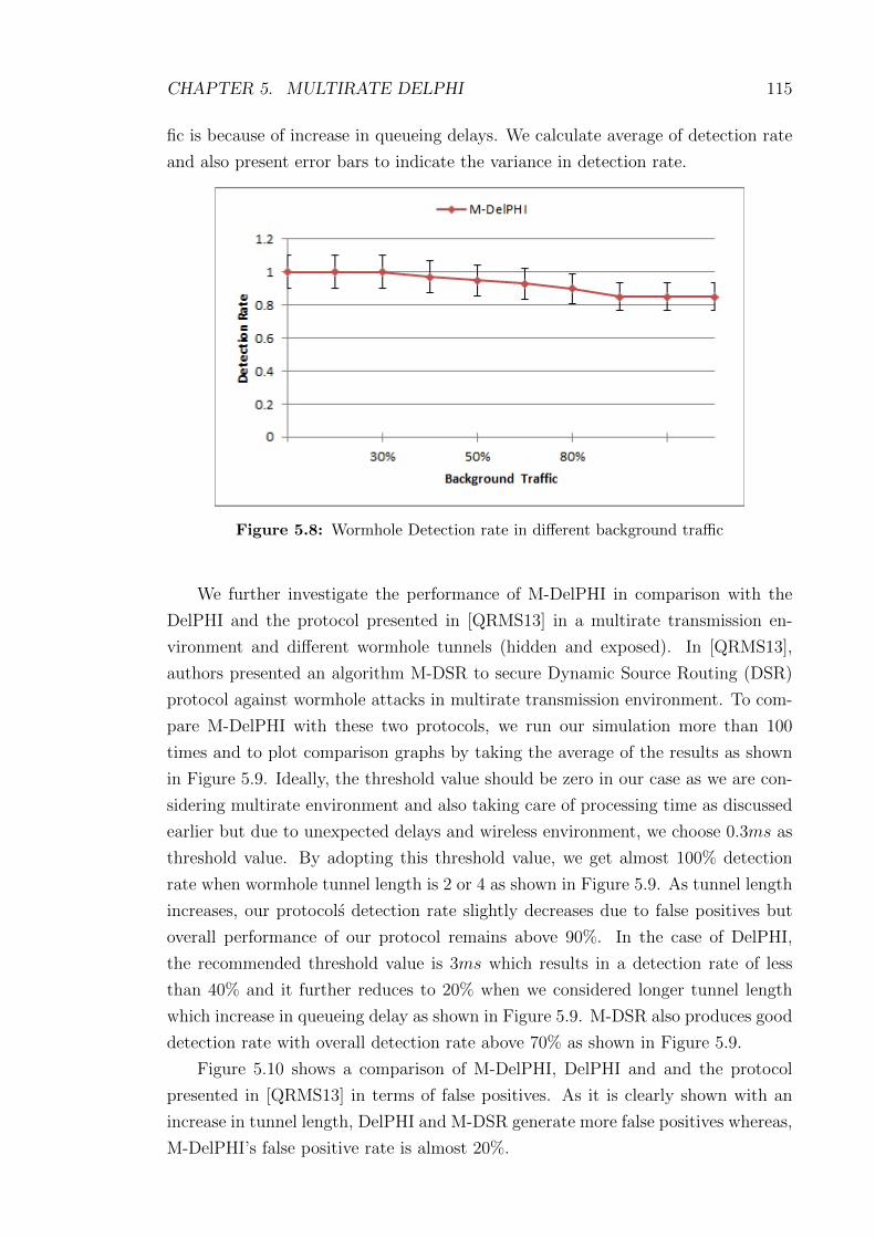
CHAPTER 5. MULTIRATE DELPHI 115
fic is because of increase in queueing delays. We calculate average of detection rate
and also present error bars to indicate the variance in detection rate.
Figure 5.8: Wormhole Detection rate in different background traffic
We further investigate the performance of M-DelPHI in comparison with the
DelPHI and the protocol presented in [QRMS13] in a multirate transmission en-
vironment and different wormhole tunnels (hidden and exposed). In [QRMS13],
authors presented an algorithm M-DSR to secure Dynamic Source Routing (DSR)
protocol against wormhole attacks in multirate transmission environment. To com-
pare M-DelPHI with these two protocols, we run our simulation more than 100
times and to plot comparison graphs by taking the average of the results as shown
in Figure 5.9. Ideally, the threshold value should be zero in our case as we are con-
sidering multirate environment and also taking care of processing time as discussed
earlier but due to unexpected delays and wireless environment, we choose 0.3ms as
threshold value. By adopting this threshold value, we get almost 100% detection
rate when wormhole tunnel length is 2 or 4 as shown in Figure 5.9. As tunnel length
increases, our protocols detection rate slightly decreases due to false positives but
overall performance of our protocol remains above 90%. In the case of DelPHI,
the recommended threshold value is 3ms which results in a detection rate of less
than 40% and it further reduces to 20% when we considered longer tunnel length
which increase in queueing delay as shown in Figure 5.9. M-DSR also produces good
detection rate with overall detection rate above 70% as shown in Figure 5.9.
Figure 5.10 shows a comparison of M-DelPHI, DelPHI and and the protocol
presented in [QRMS13] in terms of false positives. As it is clearly shown with an
increase in tunnel length, DelPHI and M-DSR generate more false positives whereas,
M-DelPHI’s false positive rate is almost 20%.

CHAPTER 5. MULTIRATE DELPHI 116
Figure 5.9: Wormhole Detection in M-DelPHI, DelPHI and M-DSR
As it can be seen from the simulation results that our M-DelPHI protocol pro-
vides above 90% detection rate against inbound and out-of-band wormhole attacks in
both static and dynamic ad hoc network scenarios under above specified simulation
parameters.
5.4.2 Potential Failure Mode Analysis
In this section, we discuss about the potential failure mode of our proposed protocol.
In our simulations, we considered both static and dynamic wireless ad hoc networks
and our proposed protocol M-DelPHI worked exceptionally well with the detection
rate above 90% in both of the scenarios. As we discussed earlier that wormhole
tunnels can be launched by the malicious nodes in different ways such as Inbound
tunnel (through packet encapsulation) or out-of-band tunnel (through direct high
speed wireless or wired link). Our protocol works well in both types of tunnels
but it may not work properly in the case of out-of-band tunnel launched by using
directional antennas or direct wired link between the malicious nodes.
Here we elaborate further on this. We assume an ad hoc network as shown in
Figure 5.11 and node S wants to start communication with node D without any
prior routing information. IEEE802.11g is the MAC and physical layer protocol
with multirate data transmission as shown in Figure 5.11. M1 and M2 are two
malicious nodes connected through directional antenna high speed link as shown in
Figure 5.11.
M-DelPHI may fail to detect wormhole attack in this scenario as malicious
nodes can easily modify route request/reply times and neighbouring nodes can not

CHAPTER 5. MULTIRATE DELPHI 117
Figure 5.10: False Positive in M-DelPHI, DelPHI and M-DSR
monitor these because of directional antenna tunnel. According to M-DelPHI, all
neighbouring nodes monitor route request/reply reception and forwarding times by
all the participating nodes which is further used by the source node to verify the route
request/reply times received with the route reply packet. By using this mechanism,
the source node can detect any modification done by the malicious nodes to alter
the actual route request/reply reception and forwarding times to deceive the source
node.
In case of directional antenna wormhole tunnel as shown in Figure 5.11, neigh-
bouring nodes are not in the communication path so can not monitor route re-
quest/reply times for the verification purposes. Therefore, the source node would
not be able to verify route request/reply times received with the route reply packet
and as a result, our protocol may fail to detect wormhole attack or may generate
false positive. Another important point in this scenario is, if M1 and M2 are part
of the network then neighbouring nodes may add them in suspicious list if neigh-
bours don’t hear specific RREQ and RREP packets being forwarded by these nodes
within time limit but if these malicious nodes are not part of the network then it is
hard to detect.
Another potential failure mode in which M-DelPHI may fail to detect or generate
false positives is if the network is highly congested and all the nodes are busy in
communication then there are chances that neighbouring nodes may not be able to
monitor participating nodes and as a result, the source node may not be able to
verify route request and reply times received with the route reply packet.

CHAPTER 5. MULTIRATE DELPHI 118
Figure 5.11: Route Request from Source to Destination
5.4.3 Computation, Memory and Transmission Overhead
In this section, we discuss the computation cost and memory overhead involved in
our protocol in comparison with DelPHI. In the case of DelPHI, total overhead is
given by:
3 ×
(N − 1 +
P∑i = 1
hi
)(5.7)
According to DelPHI, h is number of hops, P is number of disjoint paths between
source and destination and N is the total number of nodes. As a source sends route
requests three times, therefore, overhead 3 times as large.
In the case of M-DelPHI, for route setup, the source broadcasts the route request
once and the destination only replies to the first request. So if N is the total number
of nodes, h is the number of hops involved and m is the time required to calculate
the expected RTT between a node pair then the computation cost at source node
is given by:
m × (h − 1) (5.8)
Hence, this is significantly less than DelPHI, where the destination has to reply
to all request packets received from all disjoint paths P which increase the overhead.
For example, if there are 10 disjoint paths available from source to destination then
the destination has to reply to all 10 request packets which is a major overhead,
whereas, in case of M-DelPHI, the destination has to reply only first request and

CHAPTER 5. MULTIRATE DELPHI 119
if there is any wormhole detected or TTL expired then destination needs to send
another reply. Another significant overhead in DelPHI protocol is that the source
generates 3 route requests for the same route whereas, in M-DelPHI, the source
generates a route request only once (if no wormhole is detected).
We also compared the transmission overhead of M-DelPHI with DelPHI proto-
col. We run simulations for both in-band and out-of-band wormhole attacks. We
first run simulations for inbound wormhole attacks with different tunnel lengths as
mentioned in Table 5.12. We consider processing and queueing delay involved at
each node participating in the routing. We use same simulation parameters for the
DelPHI to find out the overall overhead. Figure 5.12 shows the overhead of M-
DelPHI and DelPHI. We run these simulations 100 times for different network size
(based on number of nodes) and then calculated average of overhead for both the
protocols. Overhead gradually increased with the increased number of nodes in the
network but our protocol overhead is less than the DelPHI.
Figure 5.12: Transmission overhead of DelPHI and M-DelPHI
In M-DelPHI, each node participating in the route needs to add 18 bytes of
extra data with route reply packet to store the values of TNRREQFand TNRREPF
.
This is acceptable to secure the network against wormhole attacks in multirate
environment. As mentioned earlier, in M-DelPHI, all the calculation is being done
at the source node, therefore, it is not overloading any participating nodes and all the
participating nodes just need to forward reply packet after adding their information.
Given the algorithm at hand, its complexity per route request is O(√N), if we
assume N nodes distributed equally in a 2 dimensional space. Further if there are
M route requests for the said network, then for the entire network the complexity
is O(M√N). Hence, on the route level, the algorithm is proportional to the hop

CHAPTER 5. MULTIRATE DELPHI 120
count and on the network level it is linearly proportional to route requests rather
than amount of data that is transmitted.
5.5 Summary
In this chapter, we discussed the anomalies of DelPHI in multirate transmission and
propose a M-DelPHI protocol to protect multirate wireless ad hoc networks against
wormhole attacks. In DelPHI, they consider the case of fixed rate transmission
and threshold value 3ms which results in a poor performance in case of multirate
transmission and with different background traffic as shown in Sections 3 and 5.
In our protocol, we consider multirate transmission and based upon the processing
time involved at each participating node, wormhole detection rate is above 90%,
whereas, false positives is less than 10%. In our protocol, at each node a suspicious
list is being maintained which is further used in detection of wormhole attacks as
discussed earlier. Another major difference between our protocol and DelPHI is the
processing time, as DelPHI sends route requests three times and the destination
node has to reply to each request whereas in our protocol, a source sends only one
request and if there is a wormhole detected then the source needs to send a route
request again otherwise there is no need to send another request. Our protocol
M-DelPHI does not require any special hardware or any complex calculations.
In the next chapter, we present our third security solution “Multirate Intrusion
Detection System (MIDS)” against wormhole attacks in multirate mobile ad hoc
networks which is submitted to Elsevier Journal of Network and Computer Appli-
cations (JNCA) and is currently under review.

Chapter 6
Multirate IDS
6.1 Introduction
Wide range of applications of mobile ad hoc networks make them more vulnerable
to security threats. Wormhole attack is one of the severe attacks which can be easily
implemented by adversary nodes. In this chapter, we propose an Intrusion Detection
System (IDS) to detect intrusion of adversaries in order to prevent network from
wormhole attacks. Our proposed Multirate Intrusion Detection System (MIDS) se-
cures Ad hoc On Demand Distance Vector (AODV) routing protocol in multirate
transmission environment. MIDS works on round trip time (RTT) calculation and
uses Cumulative Sum (CUSUM) algorithm to detect anomalies in round trip time
(RTT) in multirate transmission environment. Our proposed MIDS performs ex-
ceptionally well against in-bound and out-of-band wormhole attacks in multirate ad
hoc networks.
6.2 Background
An ad hoc network is a collection of mobile nodes that does not need to rely on any
predefined infrastructure and all network functions can be performed by the mobile
nodes themselves in a self-organizing manner. This results in increasing vulnerability
and security attacks in these types of networks. These include passive eavesdropping,
active interfering, impersonation, wormhole attacks and denial-of-service [HP04].
This is where Intrusion Detection System (IDS) plays a very important role to
provide security in ad hoc networks.
Unlike wired networks, intrusion prevention measures, such as strong authenti-
cation and redundant transmission, can not be used to address these attacks, due
to the reason that ad hoc nodes are mostly energy constrained and avoid intensive
computation procedures. Intrusion Detection Systems (IDS) are more effective solu-
tions that monitor the security of the network and identify any malicious behaviour.
These systems are usually less expensive to implement and can be easily deployed in
existing ad hoc networks without requiring modifications to the nodes’ configuration
or the routing protocols being used. [VGS+04b].
An IDS provides some or all of the following information: intruder identity, loca-
tion, intrusion time, intrusion activity (e.g., active or passive), intrusion type (e.g.,
121

CHAPTER 6. MULTIRATE IDS 122
attacks such as wormhole, black hole, sink hole, selective forwarding, etc.), layer
where the intrusion occurs. This information would be very helpful in mitigating
and remedying the result of attacks, since very specific information regarding the
intruder is obtained. Therefore, intrusion detection systems are very important for
network security [BMS14].
A lot of work has been done on Intrusion Detection System (IDS) for traditional
wired networks so far. However, it is not appropriate to apply directly IDSs in wired
networks into wireless ad hoc networks because of unique characteristics of wireless
networks. From the intrusion detection viewpoint, the main challenges in ad hoc
networks are their flexible network topologies, lack of concentration points where
traffic can be analysed and the most important, resource constraints. Ad hoc nodes
are normally small and inexpensive so they have limited capabilities such as limited
computational power, memory and energy. Thus, all security services for wireless
ad hoc networks must be designed with these constraints in mind. Some intrusion
detection mechanisms have been published however their performances are very
limited, either in resource usage or in effectiveness.
In this proposal, we use Round Trip Time (RTT) calculation and monitoring
mechanism to monitor network traffic and if any abrupt change or any anomaly is de-
tected in RTT then the network is considered under attacks. To detect this anomaly
or change we use non-parametric change detection algorithm known as Cumulative
Sum (CUSUM) algorithm. CUSUM is used to detect changes in RTT values between
neighbouring nodes calculated by MIDS during route discovery process. The most
important thing in our contribution is that our IDS works in multirate transmission
802.11g/n wireless channel. Our proposed MIDS is distributed in nature and only
master nodes are responsible for all computations and storage of routing tables.
This results in low computation overhead on client nodes and high effectiveness of
the proposed algorithm.
6.3 Proposed Intrusion Detection System - MIDS
In this section, we propose a Multirate Intrusion Detection System (MIDS) to detect
wormhole intrusion in multirate ad hoc networks. Certain routes get affected in the
presence of a wormhole attack and the advertised properties of these routes are
different from the actual route properties. In this proposal, we aim to exploit these
properties to detect a wormhole attack. We focus on anomaly which is based on
RTT between normal neighbours and neighbours through wormhole tunnel.
The RTT between two fake neighbours through wormhole tunnel is much shorter
or longer than the RTT of real neighbours without a wormhole tunnel. We focus on
this anomaly to detect wormhole attack in multirate ad hoc networks. For instance,

CHAPTER 6. MULTIRATE IDS 123
as shown in Figure 6.1 consider the path between nodes S and D. The advertised
route for this path goes through nodes A, M1 and M2, while the actual route taken
by packets between nodes S and D goes through nodes A, M1, F , G and M2. As
nodes F and G are hidden in advertised route therefore, RTT between nodes M1
and M2 is much greater than normal RTT between two neighbours. We exploit this
observation to detect an anomaly for an in-band wormhole tunnel.
Figure 6.1: In-band Wormhole Tunnel
In terms of out-of-band wormhole attack, the RTT between two fake neighbours
is much shorter than the RTT of two real neighbours. As shown in Figure 6.2,
wormhole tunnel endpoints M1 and M2 are connected through high speed direct
link and create an illusion that S and D are neighbours. Due to high speed direct
link, the RTT is much shorter than normal RTT between two neighbours. We exploit
this observation to detect an anomaly for an out-of-band wormhole tunnel.
The important factor is that we consider multirate transmission in our proposed
solution. Multirate transmission is an important source of shorter or longer RTT and
in the result it can effect the detection of wormhole attacks using RTT mechanism.
As shown in Figure 6.3, RTT between nodes can not be the same as transmission rate
is different between nodes. For instance, RTT between nodes S and I will remain
always less than other RTT values because of transmission rate (12Mbps) between
S and I. According to existing solutions already discussed, this difference may be
because of wormhole attack whereas, in actual it is because of lower transmission
rate between the nodes.
In the following subsections, we present system assumptions, notations, archi-
tecture and the algorithms used in our proposed MIDS to secure multirate ad hoc
networks against wormhole attacks.

CHAPTER 6. MULTIRATE IDS 124
Figure 6.2: Out-of-band Wormhole Tunnel
6.3.1 Notations
The notations used in our proposed MIDS are summarised in Table 6.1.
RREQ Route Request
RREP Route Reply
TNRREQRRoute Request receiving time of Node N
TNRREQFRoute Request forwarding time of Node N (noted by neighbors)
RREQSN RREQ packet size at specific node N
TNRREPRRoute Reply receiving time of Node N
TNRREPFRoute Reply forwarding time of Node N (noted by neighbors)
RREPSN RREP packet size at specific node N
RTTNiNj Round Trip Time between nodes Ni and Nj
MN Master Node
HT History Table
c Speed of light (3 ∗ 108m/s)
R Maximum range of wireless node (300m)
TH TH is threshold value and is equal to 0.3ms
Table 6.1: Notations
6.3.2 Systems assumptions and Definitions
We assume an ad hoc network consisting of N nodes including some specialized
nodes known as master nodes MN and communication is bidirectional over a shared
wireless medium. These MN nodes can be base stations or specialized nodes with
the support of wired or backup power connectivity, longer communication range and
more powerful processing capabilities as compared to client nodes. We also assume

CHAPTER 6. MULTIRATE IDS 125
Figure 6.3: Multirate Transmission Environemnt
that these MN are distributed in such a manner that all normal nodes N are atleast
in transmission range of one MN . We assume that M is a finite set of malicious
nodes present in the network to create wormhole attacks. We also assume that all
the nodes are working in promiscuous mode to monitor the network traffic of their
neighbours.
We use AODV [PBRD03] as the routing protocol over the IEEE 802.11g medium
access control protocol. IEEE 802.11g supports bandwidth up to a maximum of
54Mbps and approximately 22Mbps on average, and it operates in the 2.4Ghz ISM
band. Importantly and of relevance to our protocols, IEEE 802.11g supports rates
at 6, 9, 12, 18, 24, 36, 48 and 54Mbps.
We assume that all nodes remain static during any specific route request and
reply transmission. All nodes also know their and their neighbours‘ approximate
location with the help of Global Positioning System (GPS) or, if GPS is not avail-
able then the GPS-free positioning methods [CHH01, PCB00, WJH97] can be used.
We assume that each mobile node has a permanent address or End-system Unique
Identifier (EUI) and a temporary, location information called Location Dependent
Address (LDA). The The LDA is a triplet of geographic coordinates (longitude,
latitude, altitude) obtained with the help of GPS or GPS-free positioning method
[BLBG05]. We assume that there exists a location management that enables nodes
in the network to determine approximate locations of other nodes. Based on location
information, mobile nodes calculate distance between them and obtain transmission
rate accordingly with the help of lookup Table 6.2.
We present modifications to AODV routing protocol including route request and
route reply packets in the following sections.

CHAPTER 6. MULTIRATE IDS 126
Distance in Feet (Approx) Data Rate (Mbps)
≤ 60 54
≤ 100 48
≤ 150 36
≤ 200 24
≤ 225 18
≤ 250 12
≤ 275 9
≤ 300 6
Table 6.2: IEEE 802.11g Data rates based on Distance
6.3.3 Architecture of MIDS
In our proposed architecture as shown in Figure 6.4, master nodes MN are respon-
sible to do all the calculations and anomaly detection based upon RTT values and
history data stored at MN . During the establishment of a route between the source
node S and the destination node D, S broadcasts route request RREQ and all
the neighbours rebroadcast it through the network until it reaches the destination
after adding necessary information (timestamps). Once source node S receives the
reply packet RREP from the destination including all the timestamps (TNRREQR,
TNRREQF, TNRREPR
and TNRREPF), it forwards it to the master node MN for test-
ing/verification whether this route is safe or not. All the calculations and testing
are being done by the MN to save memory and power of normal nodes. MN sends
reply to the source node S about the route whether it is safe or not and also stores
that information in its routing table.
As we mentioned earlier, we use AODV as routing protocol with modifications
in route request RREQ, route reply RREP packets as shown in Tables 6.3 and
6.4. Another important difference in our protocol is that unlike AODV, each node
must forward the RREQ packet until it reaches the destination (no matter if there
is a record in its routing table or not). As we already assumed that all the nodes
are working in promiscuous mode, therefore, neighbouring nodes can monitor and
store the time when their next hop neighbour forwards the same request and reply
packets. This helps in calculation of processing time of each node by the master
node and also detection of any alteration done by a malicious node in its timestamp.
According to our proposed MIDS, each node participating in the network main-
tains its own routing table as shown in Table 6.5. This routing table also contains
the extra information RTTSD which is round trip time between source and destina-
tion. After receiving route reply packet from destination, source node forwards it
to master node as shown in Figure 6.4.
Now master node MN is responsible to do all the calculation of RTTs be-

CHAPTER 6. MULTIRATE IDS 127
0 0 0 0 0 0 0 0 0 0 1 1 1 1 1 1 1 1 1 1 2 2 2 2 2 2 2 2 2 2 3 30 1 2 3 4 5 6 7 8 9 0 1 2 3 4 5 6 7 8 9 0 1 2 3 4 5 6 7 8 9 0 1
Type J R G D U Reserved Hopcount
RREQ (Broadcast) ID
Destination Sequence number
Originator Sequence number
Destination IP address
Originator IP address
TNiRRREQ (RREQ receiving time, 0 in case of source)
TNiFRREQ (RREQ forwarding time)
Table 6.3: RREQ message format with additional fields
0 0 0 0 0 0 0 0 0 0 1 1 1 1 1 1 1 1 1 1 2 2 2 2 2 2 2 2 2 2 3 30 1 2 3 4 5 6 7 8 9 0 1 2 3 4 5 6 7 8 9 0 1 2 3 4 5 6 7 8 9 0 1
Type R A Reserved Prefix Length Hopcount
RREP ID
Destination Sequence number
Destination IP address
Originator IP address
TNiRRREQ (RREQ receiving time at each participating node)
TNiFRREQ (RREQ forwarding time at each participating node)
TNiRRREP (RREP receiving time at each participating node)
TNiFRREQ (RREP forwarding time at each participating node)
Table 6.4: RREP message format with additional fields
Destination IP Address
Destination Sequence Number
Hop Count
Next Hop
Precursor List
Expiration Time
RTTSD (RTT between Source and Destination)
Table 6.5: Routing table entry

CHAPTER 6. MULTIRATE IDS 128
Figure 6.4: Architecture of MIDS
Source IP Address
Source Sequence Number
Destination IP Address
Destination Sequence Number
RTTSDTimestamp (related to RTT)
BandwidthSD(Bandwidth between Source and Destination)
Table 6.6: History Table at Master Node
tween all the participating nodes and the MN runs the CUSUM algorithm to detect
anomalies in RTTs values. Detailed steps of testing algorithm are defined in later
subsection. Table 6.6 presents the details of history table stored at MN . This table
contains RTT and bandwidth between two neighbouring nodes along with other
necessary details as mentioned in Table 6.6.
6.3.4 Algorithms in MIDS
In this section, we present the algorithms used in our proposed MIDS to detect
wormhole attacks in ad hoc networks. The process starts with the route request
from the source node S to the destination node D. The steps involve in the route
discovery are shown in Algorithm 1. Once source node receives the reply packet,
it forwards it to the master node MN for testing and verification of route to the
destination.
Once MN receives information from the source node, it first calculates the

CHAPTER 6. MULTIRATE IDS 129
Algorithm 1 Routing request and reply between source and desti-nation.S → (Ni)
∗ : Source broadcasts route requestIf RREQ.DIP 6= Ni thenNi updates its routing table and forwards RREQ
If Ni does not hear RREQ being forwarded by any of its neigbhors(Ni+1)
∗ within time tr thenNi adds Ni+1 in suspicious list
D generates RREP on receiving RREQ and sends it back to Sthrough reverse pathS forwards RREQ and RREP packets to MN for testing
RTTs of all the node pairs participating in the route. After calculation of RTTs,
MN node run CuSUM algorithm as explained earlier to detect any anomaly in
RTT values. Algorithm 2 displays all the steps involved in this process. MN uses
history table for verification if any anomaly detected through Algorithm 2. TH is a
threshold value and used to define a constant α such that αij = E0[RTTij] + TH
which is further used in testing of RTT as explained in the Algorithm 2.
To calculate RTT of each node pair participating in the route, MN use the
following equation:
RTTij = TNiRRREP − TNiFRREQ (6.1)
As shown in Equation 1, TNiRRREP is the timestamp when node i receives
the route reply packet from node j in response of its route request packet and
TNiFRREQ is the timestamp when node i forwards the same route request packet.
As we mentioned earlier that all nodes in an ad hoc network are in promiscuous
mode, therefore, these timestamps are monitored by neighbouring nodes which are
participating in the route as well. This is considered to be more secure as if any
malicious node change any timestamps in the route reply packet then neighbouring
node can detect that change and generate an alarm as well.
We have considered the case of multirate transmission in our protocol whereas
other existing solutions only considered constant data rate which can not detect
wormholes. Our algorithms gives above 90% detection rate against both Inbound
and out-of-band wormhole attacks. As shown in Algorithm 2, E0[RTTij] is the mean
of RTT values of nodes i and j from the history table maintained by the MN . Two
different constant variables used in this algorithm, one α1ij = E0[RTTij] + TH
for checking of Inbound wormhole attack and second α2ij = E0[RTTij] − TH for
checking of out-of-band wormhole attack as mentioned in Algorithm 2.
Similarly, CUSUM runs two different hypotheses to check Inbound or out-of-
band wormhole attacks as shown in Algorithm 2. MN generates an alarm when it

CHAPTER 6. MULTIRATE IDS 130
Algorithm 2 Wormhole detection using CuSum at Master Node.
S →MN : Source forwards RREP packet to master nodeMN calculates the RTTij of each node pair participating in therouteMN assumes that
E0[RTTij] 6= E1[RTTij] and
Where E0[RTTij] is the mean of normal RTT values and E1[RTTij]is the mean of RTT values under wormhole attack.
MN considers a constantα1ij = E0[RTTij] + TH - (For Inbound Wormhole Checking)
α2ij = E0[RTTij] − TH - (For Out-of-band Wormhole Checking)
(where TH is the threshold)
Such thatE0[RTTij − α1
ij] < 0 < E1[RTTij + α1ij]
Now(RTTij)
∧ = RTTij − αij
CUSUM calculates Y nij = (Y n−1
ij + (RTT nij)∧)+ - (For Inbound
Wormhole Checking)
CUSUM calculates Y nij = (Y n−1
ij − (RTT nij)∧)+ - (For Out-of-band
Wormhole Checking)
Where Y 0ij = 01
(X)+ = x if x > 0 and (X)+ = 0 if x ≤ 0
If Y nij > 0 then
Wormhole detected between nodes i and j. To confirm this further,MN checks history table and compare the RTT between nodes iand j.

CHAPTER 6. MULTIRATE IDS 131
receives Y nij > 0 from CUSUM algorithm and confirms that a wormhole anomaly
is detected between nodes i and j. MN updates its history table accordingly and
sends reply to source nodes S that wormhole is detected between nodes i and j.
6.3.5 Working Steps of MIDS
In this section, we briefly discuss the steps involved in the working of our proposed
MIDS. As shown in the Figure 6.1, the source node S generates a route request to
start communication with the destination node D. Upon reception of route request
packet from its neighbours, D generates route reply packet and sends it back to
the source node S. Once the source node receives route reply packet from the
destination, it forwards that packet to MN for calculations and testing whether
this route is safe or not. After all the calculations and necessary testing, MN sends
reply to the source node S about the route. These working steps are listed as under:
1. S generates route request packet RREQ and broadcasts it over the network
2. RREQ is reboardcasted by all the neighbours after adding their timestamps
until it reaches the destination node D
3. D generates route reply packet RREP and forwards it back to source node S
4. After receiving RREP packet from the destination, the source node S forwards
it to MN
5. MN calculates all the RTTs as mentioned earlier and then run CUSUM Al-
gorithm to detect if there is any anomaly in RTTs or not
6. If MN finds any anomaly in RTTs, it compare it with the history table and
generates reply for the source node S
7. MN forwards reply message to the source node S that whether route is safe
or not.
8. MN updates its history table accordingly and shares it with other MN (if
any exist) as well.
9. Based on reply from the MN , source node S starts communication with the
destination D (in case of safe route) or generates another route request packet.

CHAPTER 6. MULTIRATE IDS 132
6.4 MIDS Performance Analysis
In this section, we present the performance analysis of our proposed MIDS with the
help of a simulation using ns2 [ns2]. We also discuss computation cost and memory
overhead of our solution.
6.4.1 Simulation Environment
In this section, we define simulation environment in detail including all input pa-
rameters. We distribute the nodes randomly over a square field with a fixed average
node density. Master nodes MNs are distributed in such a way that each normal
node can directly communicate with atleast one MN . The simulation parameters
are summarized in Table 6.7.
Terrain Area 1000m X 1000m
Number of Nodes 50/100/150
Tx Range(r) 150m
Channel Bandwidth 2Mbps − 54Mbps
Network Layer Protocol Modified AODV
MAC Layer Topology IEEE802.11g
Addressing Mode IPV 4
Packet Size 512Bytes
Tunnel size 2, 4, 6, 8, 10
Maximum Node Speed (10)m/s
Table 6.7: Simulation Inputs
In our simulations, we randomly selected source and destination pairs and as-
signed different bandwidths between the node pairs to highlight the effect of mul-
tirate environment. We then randomly placed the malicious nodes in the network.
We run more than 100 simulations with different data rates between node pairs and
for different number of nodes as mentioned in Table 6.7. We consider 0.3ms as a
threshold value based on simulations results in multirate transmission.
To further investigate the performance of MIDS, we run simulations in different
scenarios with different network sizes. To check the accuracy of MIDS, we initially
consider an ideal case in which we avoid processing and queueing delay of all nodes
participating in the routing and this gives us more than 85% detection rate in
both type of wormhole attacks (In-band and out-of-band). This ideal scenario also
indicates that the performance of MIDS is not effected by the number of nodes
(N = 50, N = 100 and N = 150) is above 85% as are shown in Figures 6.5 and 6.6.
Figure 6.5 displays the graph of detection of wormhole attacks (in-band and

CHAPTER 6. MULTIRATE IDS 133
Figure 6.5: Wormhole Detection
out-of-band) and also displays the value of RTT at that time interval when worm-
hole is detected. It can be easily seen from Figure 6.5 that whether the detected
wormhole is in-band or out-of-band. In terms of safe route, RTT difference is al-
ways remain 0 whereas, in terms of wormhole attack, it is either greater than 0 or
less than 0. At time interval 10ms, CUSUM detects that difference in RTT values
is more than 0.5ms so it generates an alarm about detection of In-band wormhole
attack, similarly, at time interval 25ms, it detects that the difference is −1ms so it
generates another alarm about detection of out-of-band wormhole attack.
Figure 6.6 displays the overall detection rate of our protocol against both In-
band and out-of-band wormhole attacks in multirate mobile ad hoc networks. We
run these simulations 1000 times for both type of attacks and then used average of
results as shown in Figure 6.6.
We further investigate the performance of MIDS in different background traffic
scenarios. We consider three types of background traffic light, medium and heavy.
In light background traffic we consider 30% of nodes communicating throughout the
simulation, whereas in medium background traffic, we consider 50% of nodes commu-
nicating and in heavy traffic, we consider 80% of nodes communicating throughout
the simulation. We run these simulation for both inbound and out-of-band worm-
hole attacks. For in-band attacks, we consider the tunnel length equal to 4 and
run the simulations for the same network sizes as mentioned in Table 6.7. As we
have already considered the processing and queueing delays in our protocol, we get
almost 100% detection rate for light, medium background traffic whereas, in case of
heavy background traffic, we get around 85% detection rate, as shown in Figure 6.7.
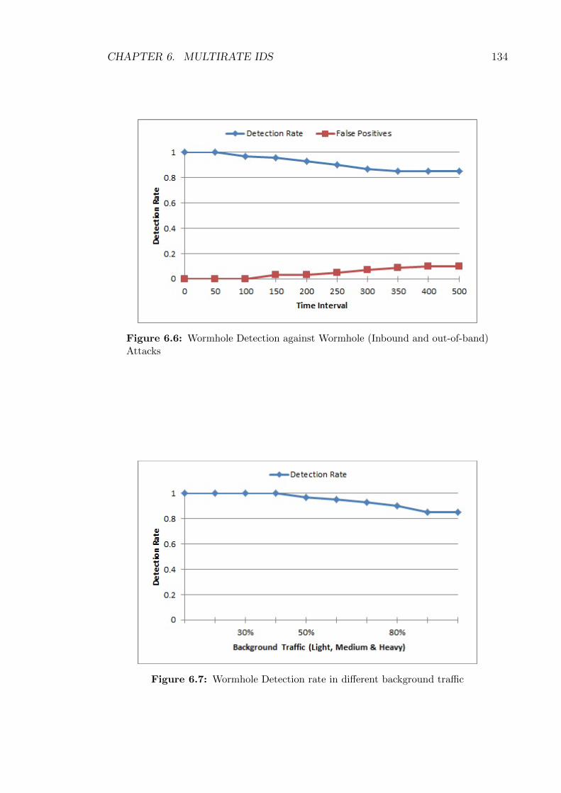
CHAPTER 6. MULTIRATE IDS 134
Figure 6.6: Wormhole Detection against Wormhole (Inbound and out-of-band)Attacks
Figure 6.7: Wormhole Detection rate in different background traffic

CHAPTER 6. MULTIRATE IDS 135
6.4.2 Computation and Memory Overhead
In this section, we discuss the computation cost and memory overhead involved in
our proposed Multirate Intrusion Detection System (MIDS). As we mentioned in
earlier sections, modified AODV route request RREQ and reply RREP packets
need some extra memory which is 8Bytes per participating node in case of request
packet and 16Bytes per participating node in case of reply packet. For example,
if 5 nodes are participating in the route between the source and the destination
then route request packet RREQ requires extra memory of 40Bytes and route reply
packet RREP requires extra memory of 80Bytes. Modified routing table entry at
each node requires an extra 8Bytes to store information about round trip time as
mentioned earlier. In order to provide security to multirate ad hoc networks against
wormhole attacks, we need to compromise for this increase in memory requirement.
In our proposed MIDS all the computations and testing is performed at master
nodes MN rather than on normal nodes participating in the route. These master
nodes MN are really powerful in terms of memory and processing speed as compared
to the normal nodes so this results in less power and memory consumption at normal
nodes. Furthermore, the CUSUM algorithm which we used for hypotheses testing
is also very light in computation and does not require any additional memory.
Given the algorithm at hand, its complexity per route request is O(√N), if we
assume N nodes distributed equally in a 2 dimensional space. Further if there are
M route requests for the said network, then for the entire network the complexity
is O(M√N). Hence, on the route level, the algorithm is proportional to the hop
count and on the network level it is linearly proportional to route requests rather
than amount of data that is transmitted.
6.5 Summary
In this chapter, we present Multirate Intrusion Detection System (MIDS) to protect
multirate wireless ad hoc networks against wormhole (Inbound and out-of-band)
attacks. All of the existing Intrusion Detection based solutions against wormhole
attacks consider the case of constant transmission rate which results in a poor per-
formance in case of multirate transmission and with different background traffic.
In our protocol, all the calculations and hypotheses testing is being done at
master nodes MN which saves the memory and power resources of normal nodes.
MN also maintains the history table as mentioned earlier and compares the current
RTT values between any node pair participating in the route to verify the pres-
ence of wormhole attack. In our proposed MIDS, CUSUM algorithm is used for
anomaly detection which is very light in computation and widely being used to de-

CHAPTER 6. MULTIRATE IDS 136
tect changes/anomalies in literature. Our simulation results show that our solution
gives overall 85% detection rate for both In-band and out-of-band wormhole attacks
and false positives is almost 10%.
Our solution also identify the malicious nodes and shares that information with
all other master nodes (in case of more than one master node) along with keeping
record of it in its history table. We also present the modified format of AODV
protocol which we use as a routing protocol. Our MIDS does not require any complex
calculations and gives 85% detection rate in multirate mobile ad hoc networks.

Chapter 7
Conclusion
In this thesis, the focus is on security of routing protocols for Mobile Ad hoc Net-
works (MANETs) against wormhole attacks in multirate transmission environment.
To the best of our knowledge, we believe that the case of multirate transmission has
not been discussed in the literature especially in this context.
Routing, or the act of discovering and forwarding packets between nodes is crit-
ical in MANETs. Securing routing protocols is very important, as this a weak point
where intruders can target the wireless devices that form the MANET. In this thesis,
we conduct a thorough study of MANETs to get a comprehensive understanding
about their applications, architecture and characteristics. We also discuss differ-
ent types of routing protocols for MANETs including their routing operations and
security requirements. We also discuss MANETs based on IEEE802.11 including
multirate scenarios in IEEE 802.11b, IEEE 802.11a, IEEE 802.11g, IEEE 802.11n.
We further discuss different types of security threats in MANETs especially worm-
hole attacks.
This thesis addressed the security threat of a wormhole attack. We proposed
three solutions that rely on Round Trip Time and statistical analysis to detect and
flag malicious nodes that attempt a wormhole attack. The work we presented is
significant, as the current state of the art does not take into account the variable bit
rate nature of the wireless channel and assumes a constant bit rate leading many
algorithms to either fail or perform sub optimally.
The first contribution of the thesis looks at securing the Dynamic Source Routing
(DSR) protocol. A further contribution is made where we combine the round trip
time with a sentinel mechanism where devices that make up the MANET monitor
each others activity to ensure against wormhole attacks. We provide two different
examples, one with fixed rate transmission and another with multirate transmission
to explain the difference of our protocol with other existing protocols. Furthermore,
it can rapidly isolate the malicious nodes to improve the performance of routing
protocols. Another benefit of our protocol is that our protocol does not require any
special hardware or any complex calculations.
The second contribution of the thesis shows that a highly cited security protocol
known as DelPHI is unable to secure Ad Hoc On Demand Distance Vector (AODV)
in a multirate transmission environment (such as IEEE 802.11g/n) and proposes
an extension to DelPHI (M-DelPHI) that adapts it to the multirate 802.11 wire-
less channel. M-DelPHI performs exceptionally well resulting in a 100% wormhole
137

CHAPTER 7. CONCLUSION 138
detection rate against in-band and out-of-band wormholes under the specified test
conditions.
The final part of the thesis uses the CUSUM method to detect any sudden
changes from the long term norm of the routing information, hence providing another
indicator of a wormhole attack. The work proposes an Intrusion Detection System
(IDS) to detect intrusion of adversaries in order to detect wormhole attacks (In-
band and out-of-band). Our proposed Multirate Intrusion Detection System (MIDS)
secures the AODV routing protocol in multirate transmission environment and the
simulation results show that the detection rate is extremely high.
Hence, the main aspects of this thesis were wormhole attacks, MANETs and
Multirate. While the constant bit rate assumption made by potentially all studies
related to MANET seems to be insignificant, it is very clear from this work that most
detection methods that rely on a timing mechanism will easily break and produce
erroneous results. Hence, this thesis highlighted the fact that making the wireless
channel constant for MANET is not a realistic assumption and further most solutions
perform very poorly when simulated under realistic wireless multirate conditions.
For future work, we plan to highlight the effects of multirate transmission in
MANETs against security threats other than wormhole attacks. We plan to propose
and implement security solutions against other routing protocol attacks in real time
wireless transmission which is multirate in nature.
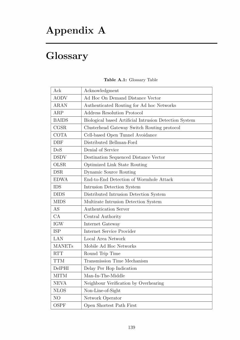
Appendix A
Glossary
Table A.1: Glossary Table
Ack Acknowledgment
AODV Ad Hoc On Demand Distance Vector
ARAN Authenticated Routing for Ad hoc Networks
ARP Address Resolution Protocol
BAIDS Biological based Artificial Intrusion Detection System
CGSR Clusterhead Gateway Switch Routing protocol
COTA Cell-based Open Tunnel Avoidance
DBF Distributed Bellman-Ford
DoS Denial of Service
DSDV Destination Sequenced Distance Vector
OLSR Optimized Link State Routing
DSR Dynamic Source Routing
EDWA End-to-End Detection of Wormhole Attack
IDS Intrusion Detection System
DIDS Distributed Intrusion Detection System
MIDS Multirate Intrusion Detection System
AS Authentication Server
CA Central Authority
IGW Internet Gateway
ISP Internet Service Provider
LAN Local Area Network
MANETs Mobile Ad Hoc Networks
RTT Round Trip Time
TTM Transmission Time Mechanism
DelPHI Delay Per Hop Indication
MITM Man-In-The-Middle
NEVA Neighbour Verification by Overhearing
NLOS Non-Line-of-Sight
NO Network Operator
OSPF Open Shortest Path First
139
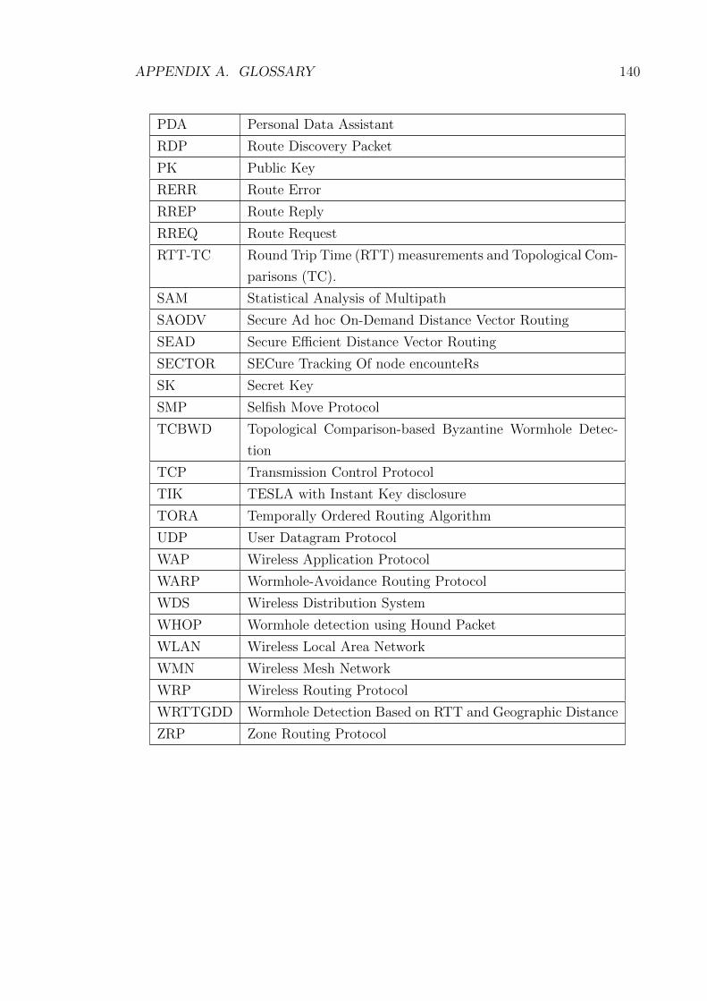
APPENDIX A. GLOSSARY 140
PDA Personal Data Assistant
RDP Route Discovery Packet
PK Public Key
RERR Route Error
RREP Route Reply
RREQ Route Request
RTT-TC Round Trip Time (RTT) measurements and Topological Com-
parisons (TC).
SAM Statistical Analysis of Multipath
SAODV Secure Ad hoc On-Demand Distance Vector Routing
SEAD Secure Efficient Distance Vector Routing
SECTOR SECure Tracking Of node encounteRs
SK Secret Key
SMP Selfish Move Protocol
TCBWD Topological Comparison-based Byzantine Wormhole Detec-
tion
TCP Transmission Control Protocol
TIK TESLA with Instant Key disclosure
TORA Temporally Ordered Routing Algorithm
UDP User Datagram Protocol
WAP Wireless Application Protocol
WARP Wormhole-Avoidance Routing Protocol
WDS Wireless Distribution System
WHOP Wormhole detection using Hound Packet
WLAN Wireless Local Area Network
WMN Wireless Mesh Network
WRP Wireless Routing Protocol
WRTTGDD Wormhole Detection Based on RTT and Geographic Distance
ZRP Zone Routing Protocol

Bibliography
[AC10] Mohammad Rafiqul Alam and King Sun Chan. Rtt-tc: A topologi-
cal comparison based method to detect wormhole attacks in manet.
In Communication Technology (ICCT), 2010 12th IEEE International
Conference on, pages 991–994. IEEE, 2010.
[ad] Ad hoc (http://www.thefreedictionary.com/ad+hoc).
[AHR04] Baruch Awerbuch, David Holmer, and Herbert Rubens. High through-
put route selection in multi-rate ad hoc wireless networks. pages 253–
270. Springer Berlin Heidelberg, 2004.
[Als11] Adel Saeed Alshamrani. Ptt: Packet travel time algorithm in mobile ad
hoc networks. In Workshops of International Conference on Advanced
Information Networking and Applications, 2011.
[AWW05] Ian F. Akyildiz, Xudong Wang, and Weilin Wang. Wireless mesh
networks: a survey. Computer Networks, 47(4):445 – 487, 2005.
[ban] Body area network (http://www.elprocus.com/best-ieee-based-real-
time-m-tech-projects-on-electronics-2014/).
[BBM98] T. Bradley, C. Brown, and A. Malis. Inverse address resolution proto-
col, rfc 2390. Technical report, September 1998.
[BCG05] R. Bruno, M. Conti, and Enrico Gregori. Mesh networks: commod-
ity multihop ad hoc networks. Communications Magazine, IEEE,
43(3):123–131, March 2005.
[Bei] Nicklas Beijar. Zone routing protocol (zrp). Networking Laboratory,
Helsinki University of Technology, Finland.
[BLBG05] Ljubica Blazevic, Jean-Yves Le Boudec, and Silvia Giordano. A
location-based routing method for mobile ad hoc networks. IEEE
Transactions on Mobile Computing, 4(2), 2005.
[BMS14] I. Butun, S.D. Morgera, and R. Sankar. A survey of intrusion de-
tection systems in wireless sensor networks. Communications Surveys
Tutorials, IEEE, 16(1):266–282, First 2014.
141

BIBLIOGRAPHY 142
[BRT+07] John S Baras, Svetlana Radosavac, George Theodorakopoulos, Dan
Sterne, Peter Budulas, and Richard Gopaul. Intrusion detection sys-
tem resiliency to byzantine attacks: The case study of wormholes in
olsr. In Military Communications Conference, 2007. MILCOM 2007.
IEEE, pages 1–7. IEEE, 2007.
[Bur03a] A Burg. Ad hoc network specific attacks. In In Seminar Ad Hoc net-
working: Concepts, Applications and Security. Technische University
Munchen, 2003.
[Bur03b] A Burg. Ad hoc network specific attacks. In In Seminar Ad Hoc net-
working: Concepts, Applications and Security. Technische University
Munchen, 2003.
[CA11] King Sun Chan and Mohammad Rafiqul Alam. Tcbwd: Topolog-
ical comparison-based byzantine wormhole detection for manet. In
Wireless and Mobile Computing, Networking and Communications
(WiMob), 2011 IEEE 7th International Conference on, pages 388–394.
IEEE, 2011.
[Cam04] S. Campadello. Peer-to-peer security in mobile devices: a user per-
spective. In Peer-to-Peer Computing, 2004. Proceedings. Proceedings.
Fourth International Conference on, pages 252–257, Aug 2004.
[CBH03] Srdjan Capkun, Levente Buttyn, and Jean-Pierre Hubaux. Sector: se-
cure tracking of node encounters in multi-hop wireless networks. In In
ACM Workshop on Security of Ad Hoc and Sensor Networks (SASN,
pages 21–32, 2003.
[CCL03] Imrich Chlamtac, Marco Conti, and Jennifer J.-N. Liu. Mobile ad hoc
networking: imperatives and challenges. Ad Hoc Networks, 1(1):13–64,
2003.
[CG03] Krishna Kant Chintalapudi and Ramesh Govindan. Localized edge
detection in sensor fields. Ad Hoc Networks, 1(2):273–291, 2003.
[CHH01] S. Capkun, M. Hamdi, and J. Hubaux. Gps-free positioning in mobile
ad-hoc networks. In Proceedings of the 34th Annual Hawaii Interna-
tional Conference on System Sciences ( HICSS-34)-Volume 9 - Volume
9. IEEE Computer Society, 2001.
[Cho03] Jong Youl Choi. Security problems for ad hoc routing protocols. Tech-
nical report, Indiana University at Bloomington, 2003.

BIBLIOGRAPHY 143
[CL06] Hon S. Chiu and King-Shan Lui. Delphi: wormhole detection mecha-
nism for ad hoc wireless networks. In Wireless Pervasive Computing,
2006 1st International Symposium on, 2006.
[Dar94] Boris S Darkhovski. Nonparametric methods in change-point prob-
lems: A general approach and some concrete algorithms. Lecture
Notes-Monograph Series, pages 99–107, 1994.
[DB92] R Gallager D Bertsekas. Data networks. Prentice Hall Inc, 1992.
[DDW99] Herve Debar, Marc Dacier, and Andreas Wespi. Towards a taxonomy
of intrusion-detection systems. Comput. Netw., 31(9):805–822, April
1999.
[DKB05a] D. Djenouri, L. Khelladi, and A. N. Badache. A survey of security
issues in mobile ad hoc and sensor networks. Commun. Surveys Tuts.,
7(4):2–28, October 2005.
[DKB05b] Djamel Djenouri, Lyes Khelladi, and Nadjib Badache. A survey of
security issues in mobile ad hoc networks. IEEE communications sur-
veys, 7(4):2–28, 2005.
[Dou02] John R. Douceur. The sybil attack. In Revised Papers from the First
International Workshop on Peer-to-Peer Systems, IPTPS ’01, pages
251–260. Springer-Verlag, 2002.
[DuKK13] Gisung Kim Dong-uk Kim, Hyo-won Kim and Sehun Kim. A
counterattack-detection scheme in transmission time-based wormhole
detection methods. International Journal of Distributed Sensor Net-
works, 2013.
[FD01] Bob Fleck and Jordan Dimov. Wireless access points and arp poison-
ing: Wireless vulnerabilities that expose the wired network. Technical
report, Cigital Inc., 2001.
[FMMT84] Ross Finlayson, Timothy Mann, Jeffrey Mogul, and Marvin Theimer.
A reverse address resolution protocol, rfc 903. Technical report, Stan-
ford University, June 1984.
[GKD11] S. Gupta, S. Kar, and S. Dharmaraja. Whop: Wormhole attack de-
tection protocol using hound packet. In Innovations in Information
Technology (IIT), 2011 International Conference on, pages 226–231,
April 2011.

BIBLIOGRAPHY 144
[GS03] Siddhartha Gupte and Mukesh Singhal. Secure routing in mobile wire-
less ad hoc networks. In Ad Hoc Networks, volume 1, pages 151–174.
Elsevier, July 2003.
[HE04] Lingxuan Hu and David Evans. Using directional antennas to prevent
wormhole attacks. In NDSS, 2004.
[HJP03] Yih-Chun Hu, David B Johnson, and Adrian Perrig. Sead: Secure
efficient distance vector routing for mobile wireless ad hoc networks.
Ad hoc networks, 1(1):175–192, 2003.
[HP04] Yih-Chun Hu and Adrian Perrig. A survey of secure wireless ad hoc
routing. IEEE Security and Privacy, 2(3):28–39, 2004.
[HPJ03a] Yih-Chun Hu, Adrian Perrig, and David B Johnson. Packet leashes: a
defense against wormhole attacks in wireless networks. In INFOCOM
2003. Twenty-Second Annual Joint Conference of the IEEE Computer
and Communications. IEEE Societies, volume 3, pages 1976–1986.
IEEE, 2003.
[HPJ03b] Yih-Chun Hu, Adrian Perrig, and David B. Johnson. Rushing attacks
and defense in wireless ad hoc network routing protocols. In in ACM
Workshop on Wireless Security (WiSe, pages 30–40, 2003.
[HPJ05] Yih-Chun Hu, Adrian Perrig, and David B Johnson. Ariadne: A secure
on-demand routing protocol for ad hoc networks. Wireless networks,
11(1-2):21–38, 2005.
[HPJ06] Yih-Chun Hu, A Perrig, and D.B. Johnson. Wormhole attacks in
wireless networks. Selected Areas in Communications, IEEE Journal
on, 24(2):370 – 380, Feb 2006.
[IH+08] Md Islam, Walaa Hamouda, et al. An efficient mac protocol for coop-
erative diversity in mobile ad hoc networks. Wireless Communications
and Mobile Computing, 8(6):771–782, 2008.
[jLG01] Sung ju Lee and Mario Gerla. Split multipath routing with maximally
disjoint paths in ad hoc networks, 2001.
[JMB01] David B. Johnson, David A. Maltz, and Josh Broch. Dsr: The dy-
namic source routing protocol for multihop wireless ad hoc networks.
Technical report, Boston, MA, USA, 2001.

BIBLIOGRAPHY 145
[KBS05] I. Khalil, S. Bagchi, and N.B. Shroff. Liteworp: a lightweight coun-
termeasure for the wormhole attack in multihop wireless networks. In
Dependable Systems and Networks, 2005. DSN 2005. Proceedings. In-
ternational Conference on, pages 612–621, June 2005.
[KBS08] Issa Khalil, Saurabh Bagchi, and Ness B Shroff. Mobiworp: Mitigation
of the wormhole attack in mobile multihop wireless networks. Ad Hoc
Networks, 6(3):344–362, 2008.
[LCWG97] W. Liu, C. Chiang, H. Wu, and C. Gerla. Routing in clustered mul-
tihop mobile wireless networks with fading channel. In Proc. IEEE
SICON’97, pages 197–211, April 1997.
[LJ] Wenjia Li and Anupam Joshi. Security issues in mobile ad hoc
networks-a survey.
[LPM+05] L. Lazos, R. Poovendran, C. Meadows, P. Syverson, and L. W. Chang.
Preventing wormhole attacks on wireless ad hoc networks: a graph
theoretic approach. volume 2, pages 1193–1199 Vol. 2, 2005.
[LSFZ09] Pan Li, Qiang Shen, Yuguang Fang, and Hailin Zhang. Power con-
trolled network protocols for multi-rate ad hoc networks. Trans. Wire-
less. Comm., 8(4):2142–2149, April 2009.
[LWZB03] Yi Lu, Weichao Wang, Yuhui Zhong, and Bharat Bhargava. Study of
distance vector routing protocols for mobile ad hoc networks. In in
Proceedings of the First IEEE International Conference on Pervasive
Computing and Communications. IEEE Computer Society, page 187,
2003.
[Mer80] Ralph C. Merkle. Protocols for public key cryptosystems. In IEEE
Symposium on Security and Privacy, pages 122–134, 1980.
[MGD07] Ritesh Maheshwari, Jie Gao, and Samir R Das. Detecting wormhole
attacks in wireless networks using connectivity information. In INFO-
COM 2007. 26th IEEE International Conference on Computer Com-
munications. IEEE, pages 107–115. IEEE, 2007.
[Mil07] Kevin L. Mills. A brief survey of self-organization in wireless sensor
networks. Wireless Communications and Mobile Computing, 7(7):823–
834, 2007.
[Mla95] Shree Murthy and J. J. Garcia luna aceves. A routing protocol for
packet radio networks. pages 86–95, 1995.

BIBLIOGRAPHY 146
[Moy97] J. Moy. Ospf version 2. Rfc: 2178, IETF, 1997.
[NAX06] Uyen Trang Nguyen, Amir Asif, and Xing Xiong. Multirate-aware
multicast routing in manets. In Mobile Adhoc and Sensor Systems
(MASS), 2006 IEEE International Conference on, pages 554–557.
IEEE, 2006.
[ns2] The network simulator ns2 (http://www.isi.edu/nsnam/ns/).
[NS07] Maitreya Natu and Adarshpal S Sethi. Intrusion detection system to
detect wormhole using fault localization techniques. In Security and
Management, pages 3–9, 2007.
[NTCS99] Sze-Yao Ni, Yu-Chee Tseng, Yuh-Shyan Chen, and Jang-Ping Sheu.
The broadcast storm problem in a mobile ad hoc network. In Mo-
biCom ’99: Proceedings of the 5th annual ACM/IEEE international
conference on Mobile computing and networking, pages 151–162, New
York, NY, USA, 1999. ACM.
[OLS03] Optimized link state routing protocol (olsr). Technical report, United
States, 2003.
[oSN] National Institute of Standards and Technology (NIST). Wireless ad
hoc network projects.
[Par01] Vincent D. Park. Temporally-ordered routing algorithm (tora). Naval
Research Laboratory, Information Technology Division, Washington,
DC 20375, 2001.
[PBRD03] C. Perkins, E. Belding-Royer, and S. Das. Ad hoc on-demand distance
vector (aodv) routing. Technical report, United States, 2003.
[PCB00] Nissanka Bodhi Priyantha, Anit Chakraborty, and Hari Balakrishnan.
The cricket location-support system. In 6th ACM MOBICOM, August
2000.
[Per01] Charles E. Perkins. An Introduction of Ad Hoc Networking. Addison
Wesley Professional, 2001.
[PH02] Panos Papadimitratos and Zygmunt J Haas. Secure routing for mobile
ad hoc networks. In the SCS Commnication Networks and Distributed
Systems Modeling and Simulation Conference (CNDS), San Antonio,
TX, January 27-31, 2002, pages 193–204, 2002.

BIBLIOGRAPHY 147
[PVA+10a] B. Prasannajit, Venkatesh, S. Anupama, K. Vindhykumari, S.R. Sub-
hashini, and G. Vinitha. An approach towards detection of wormhole
attack in sensor networks. In Integrated Intelligent Computing (ICIIC),
2010 First International Conference on, pages 283 –289, 2010.
[PVA+10b] B. Prasannajit, Venkatesh, S. Anupama, K. Vindhykumari, S.R. Sub-
hashini, and G. Vinitha. An approach towards detection of wormhole
attack in sensor networks. In Integrated Intelligent Computing (ICIIC),
2010 First International Conference on, pages 283 –289, 2010.
[QMS08] Shams Qazi, Yi Mu, and Willy Susilo. Securing wireless mesh networks
with ticket-based authentication. In Signal Processing and Communi-
cation Systems, 2008. ICSPCS 2008. 2nd International Conference on,
pages 1–10. IEEE, 2008.
[QRMSa] Shams Qazi, Raad Raad, Yi Mu, and Willy Susilo. Multirate delphi to
secure multirate ad hoc networks against wormhole attacks. Submitted
to Elsevier Journal of Computer Communications.
[QRMSb] Shams Qazi, Raad Raad, Yi Mu, and Willy Susilo. Multirate intrusion
detection system to secure multirate ad hoc networks against wormhole
attacks. Submitted to Elsevier Network and Computer Applications -
JNCA.
[QRMS13] Shams Qazi, Raad Raad, Yi Mu, and Willy Susilo. Securing dsr against
wormhole attacks in multirate ad hoc networks. Journal of Network
and Computer Applications, 36(2):582–592, 2013.
[QSL07] Lijun Qian, Ning Song, and Xiangfang Li. Detection of wormhole
attacks in multi-path routed wireless ad hoc networks: A statistical
analysis approach. Journal of Network and Computer Applications,
30(1):308 – 330, 2007.
[RT99] Elizabeth M Royer and Chai-Keong Toh. A review of current routing
protocols for ad hoc mobile wireless networks. Personal Communica-
tions, IEEE, 6(2):46–55, 1999.
[SA13] Karan Singh and Amit K. Awasthi. Quality, reliability, security and
robustness in heterogeneous networks. volume 115 of Lecture Notes of
the Institute for Computer Sciences, Social Informatics and Telecom-
munications Engineering. Springer, 2013.

BIBLIOGRAPHY 148
[SAS+15] Mehdi Sookhak, Adnan Akhundzada, Alireza Sookhak, Moham-
madreza Eslaminejad, Abdullah Gani, Muhammad Khan, Xiong Li,
and Xiaomin Wang. Geographic wormhole detection in wireless sensor
networks. PLoS One, 2015.
[SB08] Xu Su and R.V. Boppana. Mitigating wormhole attacks using passive
monitoring in mobile ad hoc networks. In Global Telecommunications
Conference, 2008. IEEE GLOBECOM 2008. IEEE, pages 1–5, Nov
2008.
[SBP13] Subir K. Sarkar, T.G. Basavaraju, and C. Puttamadappa. Ad Hoc Mo-
bile Woreless Networks, Principles, Protocols and Applications. CRC
Press, second edition, 2013.
[SDL+02] Kimaya Sanzgiri, Bridget Dahill, Brian Neil Levine, Clay Shields, and
Elizabeth M Belding Royer. A secure routing protocol for ad hoc
networks. In Network Protocols, 2002. Proceedings. 10th IEEE Inter-
national Conference on, pages 78–87. IEEE, 2002.
[SEDL03] X Ee S E D Lim. Study of secure reactive routing protocols in. mobile
adhoc networks. Technical report, National University of Singapore,
2003.
[SGTL11] Sandra Sendra, Miguel Garcia, Carlos Turro, and Jaime Lloret. Wlan
ieee 802.11 a/b/g/n indoor coverage and interference performance
study. International Journal on Advances in Networks and Services,
4(1 and 2):209–222, 2011.
[SH12] Soo-Young Shin and E.H. Halim. Wormhole attacks detection in
manets using routes redundancy and time-based hop calculation. In
ICT Convergence (ICTC), 2012 International Conference on, pages
781–786, Oct 2012.
[SLD+05] Kimaya Sanzgiri, Daniel Laflamme, Bridget Dahill, Brian Neil, Levine
Clay, Shields Elizabeth, and M. Belding-royer. Authenticated routing
for ad hoc networks. IEEE Journal On Selected Areas In Communi-
cations, 23:598–610, 2005.
[SNK05] I. Stojmenovic, A. Nayak, and J. Kuruvila. Design guidelines for rout-
ing protocols in ad hoc and sensor networks with a realistic physical
layer. Communications Magazine, IEEE, 43(3):101–106, March 2005.

BIBLIOGRAPHY 149
[SRMD14] TVP Sundararajan, SM Ramesh, R Maheswar, and KR Deepak. Bi-
ologically inspired artificial intrusion detection system for detecting
wormhole attack in manet. Wireless networks, 20(4):563–578, 2014.
[SS04] Malgorzata Steinder and Adarshpal S. Sethi. Probabilistic fault diag-
nosis in communication systems through incremental hypothesis up-
dating. Computer Networks, 45(4):537–562, 2004.
[Sta] William Stallings. Cryptography and Network Security: Principles and
Practice.
[Sta96] W. Stallings. Local & Metropolitan Area Networks. Prentice Hall,
Englewood Cliffs, NJ, 1996.
[Su10] Ming-Yang Su. Warp: A wormhole-avoidance routing protocol by
anomaly detection in mobile ad hoc networks. Computers and Se-
curity, 29(2):208 – 224, 2010.
[TH06] Bulent Tavli and Wendi Heinzelman. Mobile Ad Hoc Networks Energy-
efficient real-time data communications. Springer, 2006.
[THL+07] Phuong Van Tran, Le Xuan Hung, Young-Koo Lee, Sungyoung Lee,
and Heejo Lee. Ttm: Transmission time-based mechanism to detect
wormhole attacks. In IEEE Computer Society, pages 172–178, 2007.
[VGS+04a] Giovanni Vigna, S. Gwalani, K. Srinivasan, E.M. Belding-Royer, and
R.A. Kemmerer. An intrusion detection tool for aodv-based ad hoc
wireless networks. In Computer Security Applications Conference,
2004. 20th Annual, pages 16–27, Dec 2004.
[VGS+04b] Giovanni Vigna, Sumit Gwalani, Kavitha Srinivasan, Elizabeth M.
Belding-royer, and Richard A. Kemmerer. An intrusion detection tool
for aodv-based ad hoc wireless networks. In 20th Annual Computer
Security Applications Conference, pages 16–27, 2004.
[Wal47a] Abraham Wald. Sequential Analysis. John Wiley and Sons, 1947.
[Wal47b] Abraham Wald. Sequential Analysis. John Wiley and Sons, 1st edition,
1947.
[WAR06] Yong Wang, G. Attebury, and B. Ramamurthy. A survey of security
issues in wireless sensor networks. Communications Surveys Tutorials,
IEEE, 8(2):2–23, Second 2006.

BIBLIOGRAPHY 150
[WBLW06a] Weichao Wang, Bharat Bhargava, Yi Lu, and Xiaoxin Wu. Defend-
ing against wormhole attacks in mobile ad hoc networks. In Wireless
Communication and Mobile Computing, 2006.
[WBLW06b] Weichao Wang, Bharat Bhargava, Yi Lu, and Xiaoxin Wu. Defending
against wormhole attacks in mobile ad hoc networks: Research articles.
Wirel. Commun. Mob. Comput., 6(4):483–503, June 2006.
[WJH97] A. Ward, A. Jones, and A. Hopper. A new location technique for the
active office. IEEE Personal Communications, 4(5):42–47, 1997.
[WW07] Xia Wang and J. Wong. An end-to-end detection of wormhole attack
in wireless ad-hoc networks. International Journal of Information and
Computer Security (IJICS), 2007.
[WZW10] Yun Wang, Zhongke Zhang, and Jie Wu. A distributed approach for
hidden wormhole detection with neighborhood information. In Net-
working, Architecture and Storage (NAS), 2010 IEEE Fifth Interna-
tional Conference on, pages 63–72, July 2010.
[YLY+04] Hao Yang, Haiyun Luo, Fan Ye, Songwu Lu, and Lixia Zhang. Se-
curity in mobile ad hoc networks: challenges and solutions. Wireless
Communications, IEEE, 11(1):38–47, 2004.
[ZL05] Yongguang Zhang and Wenke Lee. Security in mobile ad-hoc networks.
In Ad Hoc Networks, pages 249–268. Springer US, 2005.
[ZLH03] Yongguang Zhang, Wenke Lee, and Yi-An Huang. Intrusion detection
techniques for mobile wireless networks. Wirel. Netw., 9(5):545–556,
September 2003.
[ZMB08] W. Znaidi, M. Minier, and J.-P. Babau. Detecting wormhole attacks in
wireless networks using local neighborhood information. In Personal,
Indoor and Mobile Radio Communications, 2008. PIMRC 2008. IEEE
19th International Symposium on, pages 1 –5, 2008.
[ZSR08] Z. Zhang, W. Susilo, and R. Raad. Mobile ad-hoc network key man-
agement with certificateless cryptography. In Signal Processing and
Communication Systems, 2008. ICSPCS 2008. 2nd International Con-
ference on, pages 1–10, 2008.