continuous-wave fiber optical parametric oscillator
TRANSCRIPT
August 15, 2002 / Vol. 27, No. 16 / OPTICS LETTERS 1439
Continuous-wave fiber optical parametric oscillator
M. E. Marhic, K. K.-Y. Wong, and L. G. Kazovsky
Department of Electrical Engineering, Stanford University, Packard 374, Stanford, California 94305
T.-E. Tsai
Photonic Technology Operations, Intel Corp., 300 Enzo Drive, San Jose, California 95138
Received March 8, 2002
We report continuous-wave operation of singly resonant fiber optical parametric oscillators. In a cavity formedby 100 m of highly nonlinear fiber and two fiber Bragg gratings, the pump power threshold was 240 mW;the output wavelength could be tuned over 80 nm by tuning of the pump. We also obtained an internalconversion efficiency of 30%, compared with the maximum theoretical value of 50%, by use of a 1-km-longcavity. © 2002 Optical Society of America
OCIS codes: 060.4370, 190.4970, 190.2620, 190.4380.
Since the nonlinearity of commonly available fibers isfairly low, obtaining suff icient gain for making a para-metric oscillator with such fibers generally requireswatt-level pump powers, which can best be providedby pulsed lasers. For these reasons, to date therehave been few reports of fiber optical parametric os-cillators (OPOs), and they have all been operated withpulsed pumps.1,2 Related devices, modulation-instability lasers,3 have been operated with a cwpump4; their output, however, is not cw but consistsof solitons.
Today, with the availability of highly nonlinearfibers (HNLFs) and high-power cw pumps, it is becom-ing possible to operate fiber OPOs in cw mode. In thisLetter we report, for the first time to our knowledge,the operation of such cw fiber OPOs. They were madefrom HNLFs, either 100 m or 1 km in length, with aFabry–Perot cavity made from two fiber Bragg grat-ings (FBGs), singly resonant at the signal wavelength;the idler constitutes the useful output. Because theidler is completely removed after each forward pass, atthe input only the signal and pump are present. Asa result the signal gain and idler conversion efficiencyare independent of the initial phases of the signal andpump. This independence is true for either a one- ora two-pump OPO. This phase independence is thesame as that found in optical parametric amplif iers(OPAs) with no idler at the input.5
With a 100-m-long HNLF with FBGs written di-rectly into it, we obtained a threshold pump powerof 240 mW but low output power. With a 1-km-longHNLF with FBGs attached by means of fiber con-nectors we extracted up to 100 mW of idler power at1566 nm, for 700 mW of pump power at 1563 nm.Excluding coupling losses, this corresponds to aninternal conversion eff iciency of 30%, compared withthe maximum theoretical eff iciency of 50%.
In a one-pump fiber OPA the small-signal gain fora signal wavelength close to that of the pump is givenby Gs � exp�2aL� �1 1 �gP0Leff �2�, where g is the fibernonlinearity coeff icient, P0 is the pump input power,Leff � �1 2 exp�2aL���a is the effective length, a is thefiber power loss coefficient, and L is the f iber length.
Let T denote the round-trip transmittance of thecold cavity, not including distributed fiber loss. Then,
0146-9592/02/161439-03$15.00/0
the threshold condition is GsT exp�2aL� � 1. For agiven L, we can solve for the value P0 that is requiredfor reaching threshold by means of the equation forX � exp�2aL�, which is TX2�1 1 r2�1 2 X�2� � 1,where r � gP0�a. This equation leads to the thresh-old pump power:
Pth �a
g
�1�T 2 X2�1�2
X�1 2 X�. (1)
For the Sumitomo HNLF used in our experiments, g �17��W km� and a � 0.2 Np�km. If we consider a shortcavity with L � 100 m and integral FBGs, so thatT � 1, we f ind that Pth � 0.12 W. However, for a longcavity with L � 1 km and FBGs attached by meansof lossy connectors, so that T � 1�20, we f ind thatPth � 0.35 W. We should thus be able to reach thresh-old with a few hundred milliwatts of pump power ineither type of cavity.
For pump power well above threshold, pump deple-tion and efficient power conversion from the pump tothe idler can occur. To quantify this, we use the samemodel that we used previously to investigate pump de-pletion in fiber OPAs,5 which is based on Jacobian el-liptic functions. The model is directly applicable tothe three waves propagating forward in the HNLF, be-cause here again there is no idler at the input. Thetheory of Ref. 5 is for lossless f ibers, but it should ap-ply well here if most of the losses are due to FBGs andconnectors, i.e., to T only. Then, the saturated gain,Gsat, should satisfy
GsatT exp�2aL� � 1 . (2)
The procedure, then, is to use the model of Ref. 5, start-ing with unknown Ps�0� and calculate Ps�L� and Gsat;this is repeated for different values of Ps�0� until Eq. (2)is satisfied. We then calculate the idler output power,Pi�L�, and the conversion eff iciency, h � Pi�L��Pp�0�.Note that for this type of OPO h cannot exceed 50%,because each pair of photons removed from the pumpprovides one photon each for the signal and the idler.
In Ref. 5 we showed that to obtain large pump deple-tion, and hence large h, one must have a propagationconstant mismatch of Db � 0.5gP0. Then, for a givenL there is an optimum P0 that leads to large depletion.These conclusions are still valid here. However, the
© 2002 Optical Society of America
1440 OPTICS LETTERS / Vol. 27, No. 16 / August 15, 2002
OPO will exhibit high h only if Eq. (2) is also satisfied.In general, for arbitrary cavity losses, this will not bethe case, and h may be well below 50%.
As an example consider the same numbersas above for the 1-km fiber and assume thatDb � 0.5gP0. Calculating Ps�0� for highest h
(in excess of 49%), we find that Ps�L��Ps�0� � 78,which is quite large. With a cavity such as the onein our experiments, for which T � 1�20, the lossesare too low for maximum depletion. Redoing thecalculation of Ps�0� to obtain Ps�L��Ps�0� � 20, we findthat the conversion efficiency is reduced to h � 29%,in good agreement with our measurements.
We expect good agreement with the theory of Ref. 5only if the backward signal power in the cavity is smallcompared with the forward powers, because then thebackward power can be neglected and the model ofRef. 5 holds. This is the case particularly if lossy con-nectors are used for attaching the FBGs to the HNLF,as in our experiment with the 1-km-long fiber. How-ever, if the backward signal power is large, then itcannot be neglected, and the predictions of the theoryof Ref. 5 may fail. This failure can be anticipated ina low-loss cavity, where the signal power is approxi-mately the same in both directions. This is the casefor our experiment with the 100-m-long fiber.
We first performed an experiment with a 1-km-longSumitomo HNLF. FBGs were made in short lengthsof Furukawa HNLF (which has parameters verysimilar to those of the Sumitomo HNLF). Standardsingle-mode fiber transitions were spliced to both typesof HNLF, and the single-mode fibers were connectedto each other by means of angle-polished connectors.Because of the diameter mismatches between thedifferent types of f iber, the splices were lossy, and asa result the cavity exhibited a one-way loss of 8 dB.
The FBGs were made by UV exposure through amask at 248 nm. HNLFs have a high GeO2 contentin the core and as a result are more photosensitivethan standard fibers. Although this greater photo-sensitivity facilitates FBG fabrication, we found thatobtaining high ref lectivities still required hydrogenloading before exposure. We then removed the H2 toreduce optical loss by heating the f iber for three daysat 80 ±C. The center wavelength of the FBGs shiftedfrom 1563 to 1560 nm during heating. Ref lectivitiesas high as 99.99% were achieved before heating, andthey remained at that level after heating.
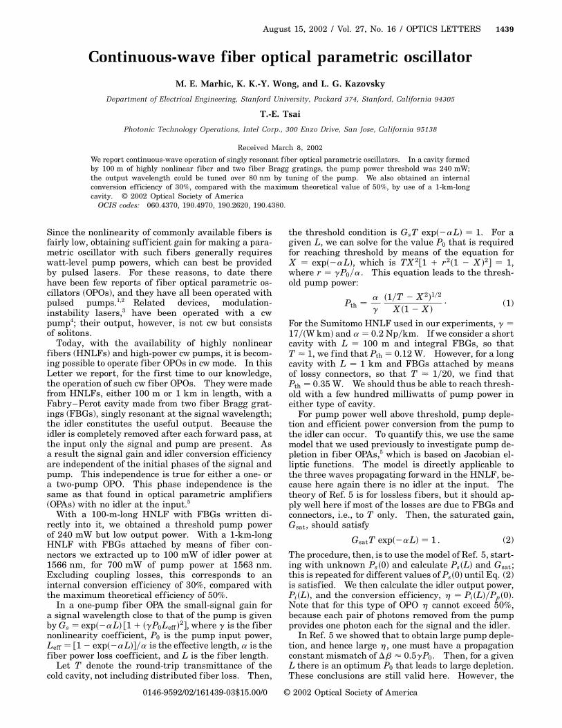
This cavity was then tested with the setup shownin Fig. 1. In the f igure, TLS is a tunable laser sourcefor the pump. Since the zero-dispersion wavelength,l0, of the HNLF that we used is �1562.5 nm, we tunedthe laser source to 1564.84 nm (pump wavelengthlp) to optimize the gain spectrum, particularly thegain near the FBG wavelength (signal wavelength,1560 nm). The tunable laser source is externallyphase modulated by a 3-GHz pseudorandom bitstream (PRBS) for suppression of stimulated Brillouinscattering. At the output of erbium-doped fiber am-plifier EDFA1, we used an optical tunable bandpassfilter (TBF) to f ilter out the amplified spontaneousemission of EDFA1. A polarization controller (PC2)after the tunable bandpass filter is used to control the
input state of polarization of the pump. The pumpis further amplif ied by a booster erbium-doped fiberamplifier (EDFA2), with a maximum output power of29 dBm. The isolator (ISO) is used to prevent anyref lection back into EDFA2.
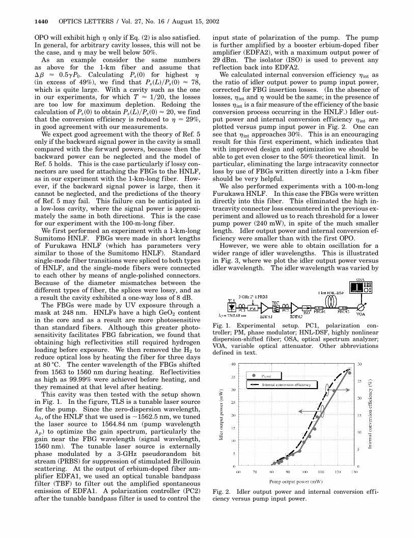
We calculated internal conversion eff iciency hint asthe ratio of idler output power to pump input power,corrected for FBG insertion losses. (In the absence oflosses, hint and h would be the same; in the presence oflosses hint is a fair measure of the eff iciency of the basicconversion process occurring in the HNLF.) Idler out-put power and internal conversion eff iciency hint areplotted versus pump input power in Fig. 2. One cansee that hint approaches 30%. This is an encouragingresult for this f irst experiment, which indicates thatwith improved design and optimization we should beable to get even closer to the 50% theoretical limit. Inparticular, eliminating the large intracavity connectorloss by use of FBGs written directly into a 1-km fibershould be very helpful.
We also performed experiments with a 100-m-longFurukawa HNLF. In this case the FBGs were writtendirectly into this fiber. This eliminated the high in-tracavity connector loss encountered in the previous ex-periment and allowed us to reach threshold for a lowerpump power (240 mW), in spite of the much smallerlength. Idler output power and internal conversion ef-ficiency were smaller than with the first OPO.
However, we were able to obtain oscillation for awider range of idler wavelengths. This is illustratedin Fig. 3, where we plot the idler output power versusidler wavelength. The idler wavelength was varied by
Fig. 1. Experimental setup. PC1, polarization con-troller; PM, phase modulator; HNL-DSF, highly nonlineardispersion-shifted fiber; OSA, optical spectrum analyzer;VOA, variable optical attenuator. Other abbreviationsdefined in text.
Fig. 2. Idler output power and internal conversion eff i-ciency versus pump input power.

August 15, 2002 / Vol. 27, No. 16 / OPTICS LETTERS 1441
Fig. 3. Experimental data points, idler output power ver-sus idler wavelength when the pump wavelength is tuned.Theoretical curve, OPA signal gain (at 1560 nm) as a func-tion of idler wavelength when the pump wavelength istuned.
tuning of the pump wavelength (we have dl�dlp � 2,since vi 1 vs � 2vp and vs is fixed by the gratings).The data points show that we were able to tune theidler wavelength over �80 nm. We also plot thetheoretical curve for OPA signal gain versus idlerwavelength, but we note that this plot cannot explainidler generation on the short-wavelength side. Anexplanation for this is obtained from the combinationof Raman gain and parametric gain that we recentlystudied.6 The Raman gain dominates for idler wave-lengths below 1530 nm, where there is very little OPAgain; i.e., we basically have a Raman laser at thesignal wavelength in this regime. The presence ofthe idler at the output can then simply be explained byfour-wave mixing between the signal and the pump.Thus we can understand the complete shape of theexperimental curve of Fig. 3 qualitatively by sayingthat this oscillator makes a continuous transition overthe tuning range from an OPO to a Raman laser aidedby four-wave mixing.
We were also able to operate this short f iber OPOwithout any pump dithering. This was accomplishedby use of a two-pump fiber OPA.7 Such an OPO has
approximately the same (total) pump power thresholdas the one-pump version, which means that each pumphas only half the required (total) power. Since theBrillouin threshold is determined by the power of eachpump, this approach in effect doubles the total pumppower that can be used before onset of stimulated Bril-louin scattering. Because of the relatively low (total)power required for OPO operation with this cavity, wewere able to reach OPO threshold before the onset ofstimulated Brillouin scattering and were thus able toturn off pump dithering.
In summary, we have demonstrated, for the f irsttime to our knowledge, cw operation of f iber opticalparametric oscillators. The cavities were made fromhighly nonlinear fiber and fiber Bragg gratings. Weobtained 30% internal conversion eff iciency witha 1-km-long fiber and external FBGs and a pumpthreshold of 240 mW and an output wavelength tuningrange of 80 nm (aided by Raman gain) for a 100-m-longfiber with integral FBGs. The results obtained withthese preliminary devices are encouraging and indi-cate that with further development cw fiber OPOscould provide an important new type of light sourcefor optical communication and other applications.
This work was supported in part by National Sci-ence Foundation grant ECS-9821026. We are grate-ful to Furukawa Electric and Sumitomo Electric forproviding HNLFs. M. E. Marhic’s e-mail address [email protected].
References
1. K. O. Hill, B. S. Kawasaki, Y. Fuji, and D. C. Johnson,Appl. Phys. Lett. 36, 888 (1980).
2. D. K. Serkland and P. Kumar, Opt. Lett. 24, 92 (1999).3. M. Nakazawa, K. Suzuki, and H. A. Haus, IEEE J.
Quantum Electron. 25, 2036 (1989).4. S. Coen and M. Haelterman, Opt. Lett. 26, 39 (2001).5. M. E. Marhic, K. K. Y. Wong, M. C. Ho, and L. G.
Kazovsky, Opt. Lett. 26, 620 (2001).6. M.-C. Ho, M. E. Marhic, Y. Akasaka, and L. G.
Kazovsky, J. Lightwave Technol. 19, 977 (2001).7. F. S. Yang, M. C. Ho, M. E. Marhic, and L. G.
Kazovsky, IEE Electron. Lett. 33, 1812 (1997).