energy from spacetime based on the parametric …aias.us/documents/uft/uft382.pdfenergy from...
TRANSCRIPT

Energy from spacetime based on the parametric
oscillator: application of the Ide device
Horst Eckardt∗
Alpha Institute for Advanced Studies (AIAS) and
Unified Physics Institute of Technology (UPITEC)
July 16, 2017
(First version: Dec. 17, 2016)
Abstract
A special parametric oscillator is designed utilizing the Ide effect (addi-tional current at hard switch-on of a transformer). According to precedingpapers, this current is a consequence of an oscillation of inductance be-fore it reaches its static value. The oscillation is utilized as a parameterchange in a serial or parallel oscillator circuit. Simulation results show anexponential growth of the current even in presence of an ohmic resistance.Concerning the energy balance, the output energy highly exceeds the in-put energy taken from the power source. Modifications of the circuit areinvestigated which avoid short cuts during switching of the power source.An inductive coupling of input is of limited useability, except the capaci-tor is moved to the primary side of the circuit. Experimental tests shouldbe executed to prove the concept being well engineerable.
Keywords: serial and parallel resonance circuit; parametric oscillator; initialcurrent; circuit theory; variable inductance; simulation model.
1 Introduction
The understanding of parametric oscillators has significantly been improved inthe last years by the joint work of the AIAS Institute and the Munich Groupof experimentalists. As described in detail in [8, 9], a parametric oscillator isa serial or parallel resonance circuit in which at least one element has variabledevice parameters in time, for example a capacitor or an inductor. When drivenconventionally, these oscillators are devices operating according to conventionalcircuit theory. The energy earned from the circuit has to be fed in by changingthe parameters of the device and there is no extra power output. Howeversuch devices are candidates for gaining energy from spacetime. The salientpoint is to find a mechanism for gathering energy in a non-conventional way.To realize this, the mechanism found by Osamu Ide is proposed [1]- [4]. Thehard switch-on of a transformer gives a current not explainable by conventionalcircuit theory. This effect was described nearly perfectly by a model based
∗e-mail: [email protected]
1
on ECE field theory [5]- [7] of the the AIAS Institute and turned out to be aprincipal mechanism suitable for obtaining energy from spacetime. We combinethis approach with the parametric circuit. Simulation results show that anenergy gain is possible in this way. In contrast to many other attempts in thefield of alternative sources of energy, this approach can quite well be understoodby theory as well as experiment and is engineerable.
When a voltage is applied to a serial resonance circuit, it is known fromclassical electrodynamics that the current rises first linearly and then goes intosaturation. The inductance of the circuit hinders the current to jump to its finalvalue immediately. In a series of papers, Osamu Ide has described experimentsrevealing an extra current in this process [1]- [4]. Actually there are two effects.When voltage is switched on in a pulse, the current oscillates strongly for lessthan a microsecond, then rises beyond the classical (linear) value in an exponen-tially decreasing way. Both effects could be explained as interactions with thebackground or spacetime potential, which becomes effective in non-continuousprocesses, in this case the hard-flanked switch-on of the voltage.
A simplified approach for explanation was derived which is based on anextension of classical circuit theory [10]. Both the experimental and theoreticalresults showed that the modulation of circuit behaviour due to spacetime effectsresults in a strong variation of the effective inductance. Therefore we will utilizethis behaviour in the following as the ‘parameter’ of the parametric circuit.
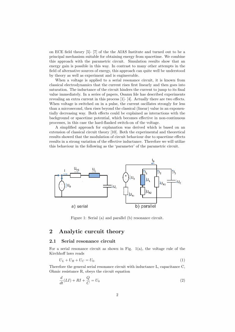
Figure 1: Serial (a) and parallel (b) resonance circuit.
2 Analytic curcuit theory
2.1 Serial resonance circuit
For a serial resonance circuit as shown in Fig. 1(a), the voltage rule of theKirchhoff laws reads
UL + UR + UC = U0. (1)
Therefore the general serial resonance circuit with inductance L, capacitance C,Ohmic resistance R, obeys the circuit equation
d
dt(LI) +RI +
Q
C= U0 (2)
2

where Q is the charge at the capacitor and I the current. Normally the de-vice properties L, R and C are assumed constant in time. For a non-constantinductance follows (see [10]):
dL
dtI + L
dI
dt+RI +
Q
C= U0, (3)
or, written with the dot for the time derivative:
LI + LI +RI +Q
C= U0 (4)
with the definition equation
I = Q. (5)
The model for the time-dependence of inductance is
L = L0
(1− exp(− t1
T1) sin(ω2t1)
). (6)
This is an exponential decay modulated by a periodic function. The time t1starts from zero at each switching point of the voltage U0. The time constant ofthe decay is T1, set to 1 µs. ω2 is the oscillation frequency of ‘ringing’, chosenas 2π · 2 MHz. L0 is the static inductance which is the asymptotic value of theoscillating phase. The resonance frequency is determined by the capacity C andasymptotic inductance L0:
f1 =1
2π
1√L0C
. (7)
As explained in [9], the parameter of the parametric oscillator has to be changeddynamically. In this case the voltage U0 is switched at instances of time wheresigns of capacitor voltage and current take the same sign:
U0 =
0 when (UC ≥ 0 and I ≥ 0)
U1 when (UL < 0 and I < 0)(8)
where U1 is the fixed voltage of the power source.
2.2 Parallel resonance circuit
Using Kirchhoff’s node current method for the parallel circuit (Fig. 1(b)) gives:
I1 + I2 + I3 = I0 (9)
and Kirchhoff’s mesh rule:
d
dt(LI1) +R2I1 = L I1 + L I1 +R2I1 = U (10)
with definitions
I2 =U
R1(11)
Q3
C=
1
C
∫I3 dt = U. (12)
3

Taking the time derivative of the third equation, we end up with the equationset
I1 + I2 + I3 = I0 (13)
LI1 + LI1 +R2I1 = U (14)
I2 =U
R1(15)
I3 = C U (16)
which are four equations for four unknowns I1, I2, I3, U . The current I0 is thedriving current. It may be difficult to realize a pure current source for I0 exper-imentally. When the driving current is to be obtained from a driving voltageU0, it may be obtained by
I0 =U0
Ri(17)
where Ri is the inner resistance of the voltage source. Based on the conditionsfor a variable inductance, the voltage U has to consist of rectangular pulses aswell as I0. It may be difficult to realize this condition for a parallel resonancecircuit. Therefore we restrict consideration to serial resonance circuits in thispaper.
3 Simulation results
3.1 Serial resonance circuit
The parametric oscillator described in section 2.1 has been simulated by anOpenModelica model [11]. In order to obtain a resonance behaviour (i.e. in-creasing voltage and current amplitudes), it is important to implement the dy-namic switching of Eq.(8). Otherwise it is difficult to get this behaviour withoutextensively adjusting the resonance frequency. This can be seen from Fig. 2where the switched voltage source U0 is graphed. the pulse width is small atthe beginning and then broadens to the expected 50% of the period. Only thisself-regulation leads safely to the wanted behaviour. In addition, in Fig. 2 thevoltage UR at the resistance is shown which is in phase with the current. It canbe seen that UR – and therefore the current – is in phase with the flanks of U0
and has strong spikes at these instances of time due to the hard switching. Theparemeter used for simulation are:
U0 = 50 V
C = 1 pF
L0 = 0.004 H
R = 20 Ω
f1 = 79.5 kHz
T1 = 1 µs
ω2 = 2π · 2 MHz
The time dependence of variable inductance L (Eq.(6)) and current I isshown in Fig. 3 on an extended time scale. There is a correspondence between
4

the oscillations in L and oscillating peaks in I. The energy input to the circuitis given by
Ein =
∫U0 I dt (18)
and the output energy is the energy dissipated by Ohmic losses:
Eout = ER =
∫R I2 dt. (19)
Both quantities are graphed in Fig. 4. Since the current always flows backinto the source, the input energy is very small. The dissipated energy increasesexponentially, showing the characteristic of this parametric oscillator. A con-ventional circuit cannot behave in this way because of the Ohmic resistance.This is a true overunity device.
3.2 Modified serial resonance circuits
As an extension of the simulation with ideal elements, we first introduce asaturation of the inductor. The effective inductance then depends on the currentand decreases significantly when the core of the inductor undergoes magneticsaturation. In a classical resonance circuit (see Fig. 5) the current amplituedreaches a maximum with an ideal inductor (red curve). As soon as the saturationeffect of the core is included (blue curve), the current decreases and stays at alower asymptotic value.
To introduce this physical behaviour into the parametric oscillator, we usedan analytic form of asymptotic L0 presented in Fig. 6. As a result, the oscilla-tions of L continue to exist, but the mean value decreases from 0.004 to 0.002H. The simulation result with this type of inductor is graphed in Fig. 7. Theoscillator now behaves opposite compared to a conventional resonance circuit.Instead of showing a saturation effect, the current further increases widely be-yond the values obtained for the ideal inductor. Both cases are displayed in Fig.7. The efficiency of the device can be increased remarkably by operating it insaturation mode of the magnetic core.
Next we compare three variants of the circuit in Fig. 1a. The calculationswere done with a fixed frequency f = 1.05 f1 for the pulsed voltage. Otherparameters are as before with additionally
R1 = 20 Ω,
R2 = 10 kΩ.
The results showed that in these cases the dynamic switching according to Eq.(8)is not required (and in some cases produced problems with the simulator). Wedefine the efficiency u of the circuit by
u =ER
Ein(20)
where ER is the sum of all Ohmic resistance contributions. Another definitionwould be to use the ratio of input and output power but this produces largespikes so that the above definition is more significant and better suited for
5

comparison. The circuit of Fig. 8a is the original circuit where the voltagehas been placed in parallel to the resistance. This limits the current when theswitching transistor is open, there is no shortcut anymore. As a drawback, theresonance is damped, but as the red curve in Fig. 9 shows, the exponentialcharacteristic remains.
In Fig. 8b and 8c the coupling to the resonance circuit is inductive by atransformer. The efficiency depends highly on the choice of resistances R1 andR2. For a real system, a parameter study has to be done to find the optimalvalues. Fig. 9 shows that for circuit 8b the efficiency remains reasonable whileit barely exceeds unity for circuit 8c. (The value for 8c is negative due to adifferent phase behaviour, only the modulus of u is relevant.) In variant 8dthe capacitor has been moved to the primary side, thus the resonance circuit iscompletely at primary side, only power is extracted secondarily. The curve u(d)in Fig. 10 (graphed separately because of different time scale) shows that thisis the best choice of circuit design. The efficiency rises exponentially again. Asalready stated, these pictures may look differently for other resistance values.
4 Conclusions
It was shown that energy from spacetime is possible if a non-standard mechanismis applied to alter a parameter (i.e. physical property) of a parametric oscillator.Such oscillators are known since the 1930ies but were very difficult to analyzebecause lack of solvable mathematical models. Therefore they are not mentionedin standard text books of electrical engineering and most engineers never heardof this during their university studies. With the advent of numerical methods,however, such model equations can be solved nearly without problems. Wedid this extensively for this article, showing that such an oscillator - althoughformally identical to a standard resonance circuit concerning the cirucit diagram- behaves completely differently, leading to an undamped resonance. Saturationeffects of the inductor do not diminish the resonance but even give an additionalboost. Introduction of additional resistances is possible in order not to damageswitching transistors. The obvious idea of driving the circuit by an inductivecoupling of the power supply unit is of limited use. It is much better to decouplethe load from the circuit by a transformer, while the load resistance must behigh compared to the resistance on the primary side. There may be a lot morepossibilities for realizing this than investigated in this work.
In future work the circuits will have to be constructed and tested. Anindispensable feature is the occurrence of the Ide effect. This is the mechanismof transferring energy from spacetime to the real hardware. It is not fully clearat the moment if the voltage peaks at the inductance are sharp enough to evokethe Ide effect in all investigated circuit variants. In addition, the mechanismhas to be made scaleable so that lower resonance frequencies and bigger devicescan be employed, producing a higher power output. If all this works well, veryhigh overunity factors can be achieved.
6
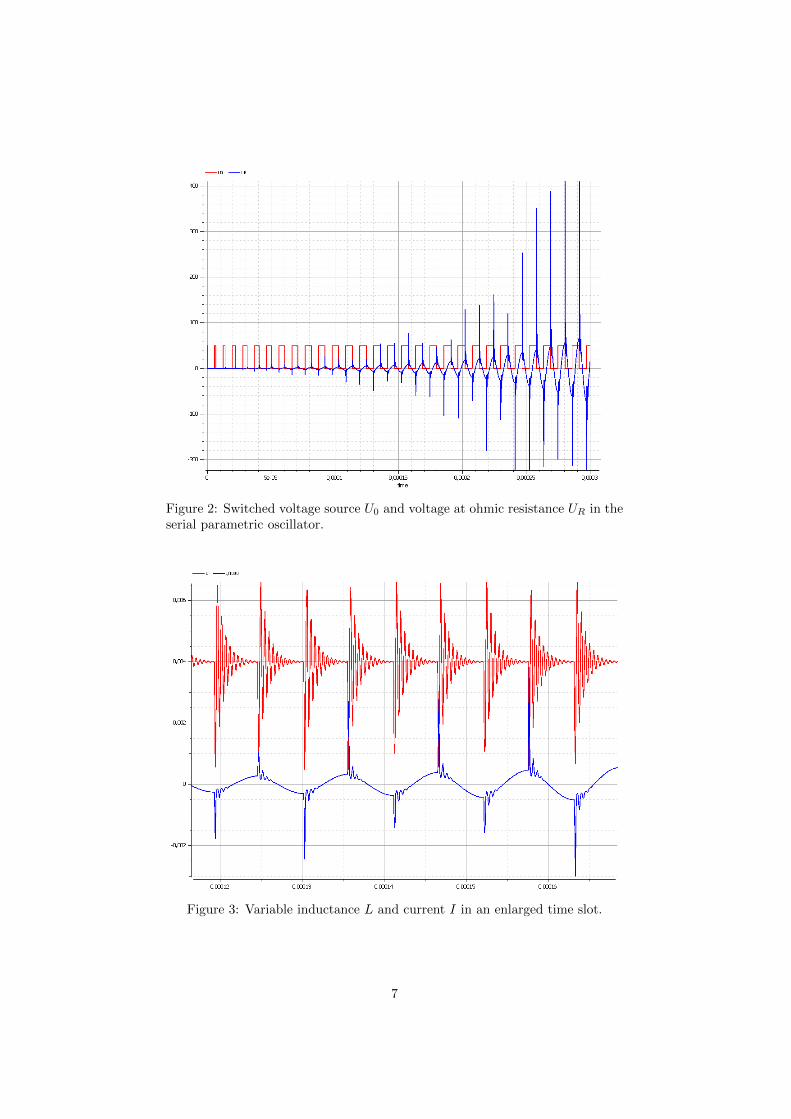
Figure 2: Switched voltage source U0 and voltage at ohmic resistance UR in theserial parametric oscillator.
Figure 3: Variable inductance L and current I in an enlarged time slot.
7

Figure 4: Input energy Ein and dissipated ohmic energy ER.
Figure 5: Current of an ideal inductor (red) and saturated inductor (blue) foran ordinary serial resonance circuit.
8
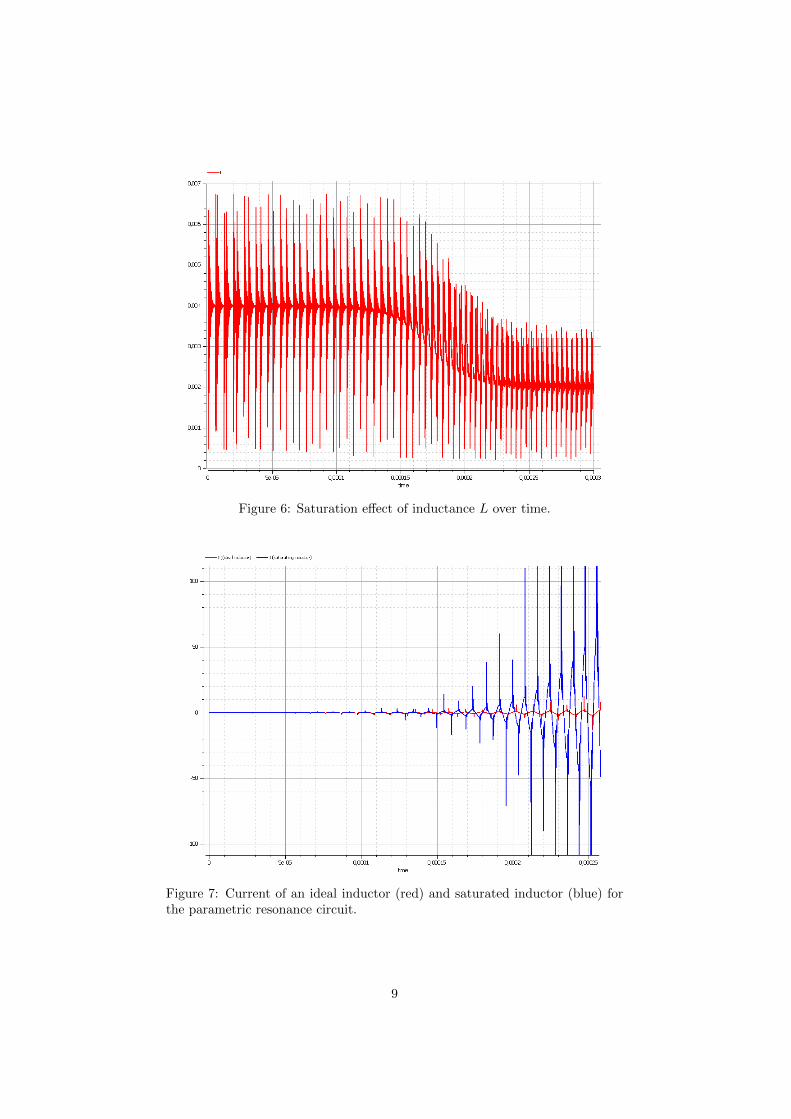
Figure 6: Saturation effect of inductance L over time.
Figure 7: Current of an ideal inductor (red) and saturated inductor (blue) forthe parametric resonance circuit.
9

Figure 8: Variants of the parametric oscillator circuit. a) source position modi-fied, b) inductive coupling for Fig. 1a, c) inductive coupling for (a), d) oscillatorcompletely in primary circuit.
Figure 9: Efficiency u for circuits of Fig. 8a-c.
10

Figure 10: Efficiency u for circuit of Fig. 8d.
11

References
[1] O. Ide, T. Yamazaki, T. Maeza, T. Funabashi, and H. Ichinose, “Consid-eration of the Cause of Inverter Noise called Ringing”, to be published inProceedings of the ACS Meeting, Denver, 2015.
[2] O. Ide, T. Yamazaki, T. Maeza, T. Funabashi, and H. Ichinose, “AnomalousRising of Input Current Induced in the Transformer of Inverter”, to bepublished in Proceedings of the ACS Meeting, Denver, 2015.
[3] O. Ide, “Characteristics of DC Power Output from an Inverter Driven bySharp Spike Pulse”, to be published in Proceedings of the ACS Meeting,Denver, 2015.
[4] Osamu Ide, “The Experiment of Self-charging Inverter driven by the 3rdPositive EMF”, poster presentation at MANA-RSC symposium in Tsukubaon 15,16 October, 2015, published on www.aias.us, 2015.
[5] M. W. Evans, H. Eckardt, C. Hubbard, J. Shelburne, “Spin ConnectionResonance in the Bedini Machine”, UFT paper 94 of www.aias.us,
[6] M. W. Evans, “Generally Covariant Unified Field Theory” (Abramis, Suf-folk, 2005 onwards), volumes one to five, also available on www.aias.us assingle articles.
[7] K. Arenhold, H. Eckardt, “Experimental verification and theoretical expla-nation of the Osamu Ide experiment”, www.aias.us, 2015.
[8] Horst Eckardt, Franklin Amador, ”‘Simulation of a Parametric ResonanceCircuit”’, AIAS web site, 2012. www.aias.us, section publications, numeri-cal solutions.
[9] Horst Eckardt, Bernhard Foltz, “Simulation of a Parametric Oscillator Cir-cuit, Part 2”, AIAS web site, 2013. www.aias.us, section publications, nu-merical solutions.
[10] Horst Eckardt, Douglas W. Lindstrom, “Circuit theory for unusual inductorbehaviour”, AIAS web site, 2015. www.aias.us, section uft papers, paper321.
[11] Openmodelica: open-source Modelica-based modeling and simulation envi-ronment, https://openmodelica.org/.
12