continuous emission monitoring systems
TRANSCRIPT

8/10/2019 Continuous Emission Monitoring Systems
http://slidepdf.com/reader/full/continuous-emission-monitoring-systems 1/31
Procedures and General Requirements
for the Compliance Testing of
Continuous Emission Monitoring Systems
Environment Agency
Version 2, Revision 1
April 2003

8/10/2019 Continuous Emission Monitoring Systems
http://slidepdf.com/reader/full/continuous-emission-monitoring-systems 2/31

8/10/2019 Continuous Emission Monitoring Systems
http://slidepdf.com/reader/full/continuous-emission-monitoring-systems 3/31
MCERTS Procedures and General Requirements for CEMs, V2, Rev 1, April 2003 i
Foreword
The Environment Agency (the Agency) has established its Monitoring Certification Scheme,
MCERTS, to deliver quality environmental measurements. The scheme provides for the
product certification of instruments, the competency certification of personnel and the
accreditation of laboratories based on international standards. MCERTS is progressively being extended to cover all regulatory monitoring activities.
MCERTS operates under the requirements of European and international standards. The
Agency has appointed Sira Certification Service (SCS) as the Certification Body to operate
MCERTS on the Agency’s behalf. SCS is independent of all the interested groups, such as
the instrument manufacturers, monitoring personnel, test-house laboratories and end-users.
The Agency has published MCERTS performance standards for continuous emission
monitoring systems (CEMs). This document specifies the procedures and describes the
general requirements for the testing of CEMs for compliance with the performance standards.All testing under MCERTS must be carried out by laboratories and test organisations that
comply with the requirements of BS EN ISO/IEC 17025 for these procedures.
Both the performance standards and the test procedures are based on relevant CEN, ISO and
national standards. Testing comprises a combination of laboratory and field tests to ensure
that instruments perform to the technical requirements and work in real applications. The
scope of the test programme and evaluation of the results is carried out by SCS, using a group
of independent experts known as the Certification Committee.
If you have any questions regarding the testing of CEMs under MCERTS, please contact:
Sira Certification Service Tel: +44 (0)208 467 2636
South Hill Fax: +44 (0)208 295 1990
Chislehurst
Kent BR7 5EH
If you have any general questions about MCERTS, please contact:
Environment Agency Tel: +44 (0)1772 714362
Monitoring & Assessment Process Fax: +44 (0)1772 714360
Lutra House
off Seedlee Road
Walton Summit
Preston PR5 8BX
or visit the MCERTS website at www.environment-agency.gov.uk/mcerts/
Dr Mick Pearson
Head: Monitoring & Assessment Process
March 2003

8/10/2019 Continuous Emission Monitoring Systems
http://slidepdf.com/reader/full/continuous-emission-monitoring-systems 4/31
MCERTS Procedures and General Requirements for CEMs, V2, Rev 1, April 2003 ii

8/10/2019 Continuous Emission Monitoring Systems
http://slidepdf.com/reader/full/continuous-emission-monitoring-systems 5/31
MCERTS Procedures and General Requirements for CEMs, V2, Rev 1, April 2003 iii
Contents
1. Introduction........................................................................................................................1
2. Scope....................................................................................................................................1
3. References ...........................................................................................................................1
4. Definitions ...........................................................................................................................2
5. Provisions for test organisations.......................................................................................5
5.1 General requirements for test-houses and testing ......................................................5
5.2 Procedures and documentation...................................................................................6
5.3 Measurement equipment and calibration gases..........................................................6
5.4 Performance evaluation..............................................................................................6
5.5 Paired testing of instruments......................................................................................6
5.6 Reporting....................................................................................................................6
6. Laboratory test procedures...............................................................................................7
6.1 Screening checks – all CEMs.....................................................................................7
6.2 Operating environments – all CEMs..........................................................................86.3 Specific tests for gas monitoring CEMs...................................................................10
6.4 Specific tests for TOC monitoring CEMs ................................................................14
6.5 Specific tests required for particulate measuring instruments .................................16
6.6 Specific requirements for CEMs monitoring temperature, pressure and flow.........16
7. Field test requirements ....................................................................................................17
7.1 General requirements for all CEMs .........................................................................17
8. Status of this document....................................................................................................21
Appendix 1: Required format for reports on performance evaluation of CEMs.......22
Appendix 2: Interfering compounds...............................................................................24
Appendix 3: Standard reference methods......................................................................25

8/10/2019 Continuous Emission Monitoring Systems
http://slidepdf.com/reader/full/continuous-emission-monitoring-systems 6/31
MCERTS Procedures and General Requirements for CEMs, V2, Rev 1, April 2003 iv
8/10/2019 Continuous Emission Monitoring Systems
http://slidepdf.com/reader/full/continuous-emission-monitoring-systems 7/31
MCERTS Procedures and General Requirements for CEMs, V2, Rev 1, April 2003 Page 1 of 25
Procedures and General Requirements for the Compliance Testing of
Continuous Emission Monitoring Systems
1. Introduction
1.1.1 This document describes the test procedures and general requirements for the testingof continuous emission monitoring systems (CEMs) for compliance with the
MCERTS performance standards. It also describes the specific, supplementary
provisions for MCERTS-certified CEMs to be accepted by the Umweltbundesamt
(UBA) for inclusion on the German Federal Register of approved equipment.
2. Scope
2.1.1 The procedures and requirements in this document cover both laboratory and field
compliance testing of CEMs under MCERTS.
3. References
3.1 Normative references
a) BS EN 45001 (1998). General criteria for the operation of testing laboratories.
b) BS EN ISO/IEC 17025 (2000). General requirements for the competence of
testing and calibration laboratories.
c) Performance Standards for Continuous Emission Monitoring Systems – The
Environment Agency’s Monitoring Certification Scheme (MCERTS),
Version 2, Revision 1, April 2003.
3.2 General references
d)
BS 6069 Section 4.4 (1993). Stationary source emissions – Determination of
the mass concentration of sulphur dioxide – Performance characteristics of
automated measuring methods. Also known as ISO 7935.
e) BS EN 12619 (1999). Determination of the mass concentration of TOC at low
concentrations in flue gases.
f) BS EN 13526 (2002). Determination of the mass concentration of TOC at high
concentrations in flue gases.
g) BS EN 50081-1 (1992). Electromagnetic compatibility. Generic emission
standard. Residential, commercial and light industry.h) BS EN 50081-2 (1994). Electromagnetic compatibility. Generic emission
standard. Industrial environment.
i) BS ISO 6879 (1995). Air quality – Performance characteristics and related
concepts for air quality measurements.
j) BS ISO 10155 (1995). Stationary source emissions – Automated monitoring
of mass concentrations of particles – Performance characteristics, test methods
and specifications.
k) BS ISO 14164 (1999). Stationary source emissions – Determination of volume
flow rate of gas streams in duct – automated method.
l) ISO 9169 (1994). Air quality – Determination of performance characteristics
of measurement methods. Also Amendment 1 (CD) (1998).m) ISO 10396 (1993). Stationary source emissions – Sampling for the automated

8/10/2019 Continuous Emission Monitoring Systems
http://slidepdf.com/reader/full/continuous-emission-monitoring-systems 8/31
MCERTS Procedures and General Requirements for CEMs, V2, Rev 1, April 2003 Page 2 of 25
determination of gas concentrations.
n) ISO 10849 (1996). Stationary source emissions – Determination of mass
concentration of nitrogen oxides – Performance characteristics of automated
measuring systems.
o)
ISO 12039 (2001). Stationary source emissions – Determination of the
volumetric concentration of CO, CO2 and oxygen – Performancecharacteristics and calibration of an automated measuring system.
p)
BS EN 60359 (2002). Electrical and electronic measurement equipment.
Expression of performance
q) MCERTS – Guidance on the Acceptance of German Type Approval Test
Reports for CEMs, Environment Agency, 2001.
r) VDI 4203, Part 1 (2001). Testing of automated measuring systems. General
concepts.
s) VDI 4203, Part 2 (2001). Testing of automated measuring systems. Test
procedures for measuring systems of gaseous and particulate emissions.
t) IEC 60068-1 (1988-06)
u)
Environmental testing. Part 1: General and guidance
v) IEC 60068-2, Parts 1 to 81, Environmental testing, specific requirements..
4. Definitions
4.1 Accuracy: The closeness of agreement between a single measured value of the
determinand and the true value (or an accepted reference value).
4.2 Analysis function: Statistical relationship between the starting variable (signal
measured) of the measuring system and the associated measurement result
(measured value) simultaneously determined at the same point of measurementusing a standard method of reference measurement.
NOTE 1: The analysis function is normally calculated using linear regression.
NOTE 2: ISO 10155 uses the term “calibration function” to refer to this function. This use of the term conflicts
with other ISO standards (for example, ISO 6879) and VDI. Within MCERTS, the term “analysis
function” is used to avoid such inconsistencies.
4.3 Availability: The fraction of the total monitoring time for which data of acceptable
quality have been collected.
4.4 Averaging time: The period of time over which an arithmetic or time-weighted
average of concentrations is calculated. [T a is the averaging time used by the CEM.T ra is the required data averaging period, e.g. prescribed by legislation.]
4.5 CEM: Acronym for a continuous emission monitoring system. Entirety of all
measuring instruments and additional devices for obtaining a measurement result.
NOTE 1: Apart from the actual measuring device (the analyser), a CEM includes facilities for taking samples
(e.g. probe, sample gas lines, flow meters and regulator, delivery pump), for sample conditioning (e.g.
dust filter, pre-separator for disturbing components, cooler, converter) and for recording. This
definition also includes testing and adjusting devices that are required for functional checks and, if
applicable, for commissioning.
NOTE 2: CEM is an alternative term for “automatic measuring system” (AMS), which is the term used
elsewhere in Europe.

8/10/2019 Continuous Emission Monitoring Systems
http://slidepdf.com/reader/full/continuous-emission-monitoring-systems 9/31
MCERTS Procedures and General Requirements for CEMs, V2, Rev 1, April 2003 Page 3 of 25
4.6 Certification range: The determinand values over which the instrument is to be
tested, bounded by specified upper and lower limits. Testing takes place within the
certification range.
4.7 Converter efficiency: The efficiency with which the internal converter unit of a
NO x analyser reduces NO2 to NO.
4.8 Cross-sensitivity: Response of the CEM to determinands other than those it is
designed to measure. See Interference.
4.9 Detection limit: This is the concentration value of the determinand below which
there is at least a 95% level of confidence that the measured value corresponds to a
sample free of that determinand.
4.10 Delay time, T 10: The time taken for the output reading of the CEM to reach 10% of
the total change in instrument response.
4.11 Expanded uncertainty: Quantity defining a level of confidence about the result of
a measurement that may be expected to encompass a specific fraction of the
distribution of values that could reasonably be attributed to a determinand.
NOTE: The level of confidence would typically be 95%.
4.12 Field repeatability: A measure of the 95% level of confidence interval of the
difference of measuring results from two CEMs used under identical conditions.
NOTE 1: The term “reproducibility” is sometimes used instead of “field repeatability”.
4.13 Gas analyser: An analytical instrument that provides an output signal that is a
function of the concentration, partial pressure, flow or temperature of one or morecomponents of a gas mixture.
4.14 Integral performance: The integral performance is defined as a measure of the
working accuracy of the CEM. The integral performance is derived from the
differences in pairs of measured values of the determinand by the CEM and
reference method. There must be a sufficient number of paired measurements spread
over the period of unattended operation. It is calculated according to the formula for
standard deviation.
The difference in uncertainties between the measurements from the CEM and the
reference methods is defined in equation (1):
2
C
2
DF S S I −= (1)
where S D is derived from the uncertainty in the differences between the CEM and
SRM measurements using equation (2):
−
−= ∑∑
==
2
11
2
D
1
1
1 n
i
i
n
i
i Z n
Z n
S (2)

8/10/2019 Continuous Emission Monitoring Systems
http://slidepdf.com/reader/full/continuous-emission-monitoring-systems 10/31
MCERTS Procedures and General Requirements for CEMs, V2, Rev 1, April 2003 Page 4 of 25
where
Z i = X i – Y i;
X i = individual result obtained by the SRM;
Y i = mean result obtained by the CEM over the same time period as that taken to
perform SRM measurement;
n = number of measurement pairs;S C = known standard deviation in the results obtained by the SRM. (It is generally
given in CEN/ISO standards describing the appropriate methods – for
example, ISO 7934.)
4.15 Interference: A negative or positive effect that a substance has upon the output of
the instrument when that substance is not the target determinand.
4.16 Interferent: Component of the sample, excluding the measured constituent, that
affects the output signal.
4.17 Limiting conditions: The extreme conditions that an instrument can withstand
without damage and any decrease in its abilities to perform reliable measurements
when it is working under its rated operating conditions.
4.18 Linearity: Measure of fit of the instrument’s response to a straight line using a
number of samples of approximately equally distributed concentrations of a
pollutant and a zero concentration.
4.19 Linearity error: The maximum deviation between the actual analyser readings and
the best-fit line (linear regression line).
4.20 Maintenance interval: Maximum admissible interval of time for which the
performance characteristics will remain within a predefined range without servicing,
e.g. refill, calibration, or adjustment.
4.21 Output: A reading, or a digital or analogue electrical signal, generated by an
instrument in response to a determinand.
4.22 Performance characteristic: One of the quantities (described by values, tolerances,
range) assigned to equipment in order to define its performance.
4.23 Reference conditions: A specified set of values (including tolerances) of influencevariables delivering representative values of performance characteristics.
4.24 Reference material: A substance or mixture of substances, with a known
composition within specified limits. One or more of the properties of the reference
material are sufficiently well established over a stated period of time to be used for
the calibration of an apparatus, for the assessment of a measuring method or for
assigning values to materials.
4.25 Repeatability: The ability of a CEM to provide closely similar indications for
repeated applications of the same determinand under the same conditions of measurement.

8/10/2019 Continuous Emission Monitoring Systems
http://slidepdf.com/reader/full/continuous-emission-monitoring-systems 11/31
MCERTS Procedures and General Requirements for CEMs, V2, Rev 1, April 2003 Page 5 of 25
4.26 Response time, T 90: The time taken for the output indicator reading of the CEM to
reach 90% of the total change in CEM response.
4.27 Span: Difference of the instrument readings between zero and a stated determinand
value. By convention, this determinand value is chosen to be 70% to 80% of the
upper limit of the measurement.
4.28 Span drift: The change in instrument reading in response to a specified value of a
determinand over a stated period of unattended operation.
4.29 Stable test gas mixture: A mixture of gases where the component to be measured is
known and neither reacts with the containment system, nor is adsorbed on to it (e.g.
a cylinder).
4.30 Standard uncertainty: Uncertainty of the result of a measurement expressed as a
standard deviation.
4.31 Uncertainty: The parameter associated with the result of a measurement that
characterises the dispersion of the values that could reasonably be attributed to the
determinand.
4.32 Zero gas: A gas mixture used to establish the zero point of a calibration curve when
used with a given analytical procedure within a given calibration range.
4.33 Zero drift: The change in instrument reading in response to a zero value of the
determinand over a stated period of unattended operation.
5. Provisions for test organisations
5.1 General requirements for test-houses and testing
5.1.1 Test organisations shall comply with the requirements of BS EN ISO/IEC 17025 for
testing of CEMs under MCERTS and possess the necessary equipment and
capabilities to perform the tests specified in this document.
NOTE 1: Demonstration of compliance shall be either through accreditation by a national accreditation body, or
by a successful audit to EN ISO/IEC 17025 by the MCERTS Certification Body.
NOTE 2: Prior to March 2002, test organisations had to comply with the requirements of BS EN 45001.
5.1.2 Instrument testing would normally begin in the laboratory. If the instrumentsuccessfully passes the laboratory tests, then it proceeds to the three-month field
tests.
5.1.3 When performing the tests, the test-house must consider each performance
characteristic on its own. In the case of multiple-component CEMs, the evaluation
must cover the influence of intended combinations of measurement components on
the performance of the CEM.
5.1.4 If a CEM does not meet any of the requirements in the performance standards, then
the test-house must inform the Certification Body without delay.
8/10/2019 Continuous Emission Monitoring Systems
http://slidepdf.com/reader/full/continuous-emission-monitoring-systems 12/31
MCERTS Procedures and General Requirements for CEMs, V2, Rev 1, April 2003 Page 6 of 25
5.2 Procedures and documentation
5.2.1 The test-house shall have documented procedures to provide for the applicable test
requirements in Sections 6 and 7 of this document.
5.2.2 The test-house shall retain the test records and reports, as well as all documents of
importance for at least five years.
5.3 Measurement equipment and calibration gases
5.3.1 All equipment and calibration gases used for evaluating the performance of CEMs
shall be verified as fit for purpose. This shall include certificates of calibration
traceable to national standards.
NOTE: Any combination of cylinders, gas blenders, dilution systems and permeation tubes may be used to
generate test and calibration gases.
5.4 Performance evaluation
5.4.1 The test-house shall evaluate the performance of the CEM for compliance with therelevant MCERTS performance standards. The requirements of the appropriate tests
are described in Sections 6 and 7.
5.5 Paired testing of instruments
5.5.1 Testing for MCERTS certification shall be performed on a minimum of one
instrument for gas monitoring CEMs and one instrument for the laboratory tests for
particulate monitoring CEMs. Two instruments are required for the field test for
particulate monitoring CEMs to determine field repeatability.
5.5.2 Two instruments shall be tested in all cases where the manufacturer requires theMCERTS-certified CEM to be accepted by the Umweltbundesamt (UBA) for
inclusion on the German Federal Register of approved equipment. Both instruments
are required to pass all the laboratory and field tests.
5.6 Reporting
5.6.1 The test-house shall produce a report describing the test programme and the results
of the evaluation. This test report shall contain at least the following:
• a description of the CEM under test, including the manufacturer, type and
unique identity;• a description of the test programme;
• a description of the methods and reference tests employed in the
programme;
• any deviations from the standard methods;
• the results of the test;
• details of necessary maintenance work and remedial actions required to
ensure that the equipment meets the performance standards;
• a proposed scope of capabilities to be included on the certificate;
• a summary table stating the required performance characteristics for each
parameter, a statement of pass or fail, and a reference to the relevant section
of the test report.
8/10/2019 Continuous Emission Monitoring Systems
http://slidepdf.com/reader/full/continuous-emission-monitoring-systems 13/31
MCERTS Procedures and General Requirements for CEMs, V2, Rev 1, April 2003 Page 7 of 25
5.6.2 The operating instructions, the manufacturer’s description of the equipment as well
as other relevant information shall be attached to the test report.
5.6.3 Appendix 1 describes the required format for the report.
6. Laboratory test procedures
6.1 Screening checks – all CEMs
(i) Instrument receipt, set-up and adjustment
6.1.1 Upon receipt of the CEM, the test-house shall check that the manufacturer has sent
an appropriate and complete CEM, plus instructions for use.
6.1.2 The test-house shall ensure that the CEM is set up, calibrated and adjusted in
accordance with the manufacturer’s instructions.
NOTE: The manufacturer is normally expected to install and set up the CEM.
(ii) Short-term drift and repeatability
6.1.3 The test-house shall have procedures to screen the stability and response of the
CEM. Such procedures can include an evaluation of short-term drift and
repeatability. Typically, a CEM shall be allowed to warm up, after which it is
supplied with a zero or span gas. If the reading drifts significantly or the signal is
unacceptably noisy, then the tests shall be terminated until the Certification Body
decides on the appropriate course of action.
NOTE: As a guideline, the instrument’s response should not drift more than 2% of the certification range over
24 hours and have a noise level that is less than 2% over the same period.
(iii) Prevention of unauthorised adjustment
6.1.4 The test-house shall evaluate the effectiveness of the mechanism that prevents
inadvertent and unauthorised adjustment.
(iv) Position of zero point and reference point on the device display
6.1.5 The test-house shall use a zero gas and a reference gas to determine whether the zero
point is between 10% and 20% of the full-scale deflection (FSD) and whether the
span point is between 70% and 80% of the range.
(v) Indicating range
6.1.6 The test-house shall determine whether the indicating ranges are appropriate and can
be adjusted for the required tasks.
(vi) Supplementary data outputs
6.1.7 The test-house shall verify by inspection that the CEM has a supplementary output
for an external data recording device, and whether the measurement signals
displayed on an external device are the same as those on the CEM.

8/10/2019 Continuous Emission Monitoring Systems
http://slidepdf.com/reader/full/continuous-emission-monitoring-systems 14/31
MCERTS Procedures and General Requirements for CEMs, V2, Rev 1, April 2003 Page 8 of 25
(vii) Status signals
6.1.8 The test-house shall verify by inspection whether the CEM has provisions for
displaying its operational status, whether the mechanisms are effective and the
displayed status is correct.
NOTE: Status signals include indication of normal operation, calibration and faults. Not all fault conditions
require evaluation.
(viii) Automatic corrections for zero and span drift
6.1.9 If CEMs are equipped with an automatic function to correct zero and span drift, then
the test-house shall determine the maximum permissible correction range in which
readjustment is possible.
6.1.10 Initially, the test-house shall admit a test gas or other test media at the zero and
reference point and repeat this exercise three times. Then the test-house shall alter
the settings of the analyser so that such an adjustment simulates a zero and span
drift. The test-house shall then determine whether the automatic correction functionseffectively and corrects the simulated drift.
NOTE: This test is also repeated during the field test.
6.2 Operating environments – all CEMs
6.2.1 The CEM shall be tested to show whether it is influenced by changes in operating
environments as specified in this section.
6.2.2 The extent of the environmental testing will be agreed between the manufacturer
and the Certification Body, taking into account the environment likely to be
encountered in the industrial process(es) for which product certification is sought.
NOTE: The Certification Body will consider whether different components of CEMs should be subjected to
different levels of environmental testing (for example, the stack-mounted components will in general
require more rigorous tests than components mounted off-stack).
6.2.3 During the tests, the CEM shall be subjected to the specified range of environmental
conditions and the changes in its zero and span values determined. The range of
conditions tested will be reported on the certificate.
(i) Mains voltage
6.2.4 Using an isolating transformer, the test-house shall vary the voltage to the CEM in
10 V increments, varying the voltage from 230 V to 190 V and then from 230 V to250 V. The test shall be performed at the zero point and at the span point. The
measurement signals shall be recorded in each case and the test shall be repeated at
least three times.
(ii) Vibration
6.2.5 When required by the Certification committee, this test shall be applied to stack-
mounted components of the CEM only and shall be made with reference to IEC 68-
1/2 ( Basic Environmental Testing Procedures) recommendations. The instrument
shall be subjected to vibration on three perpendicular axes in turn, with a swept
range of frequencies from 10 Hz to 150 Hz at one octave per minute and at an RMS
acceleration of 19.6 m s –2.

8/10/2019 Continuous Emission Monitoring Systems
http://slidepdf.com/reader/full/continuous-emission-monitoring-systems 15/31
MCERTS Procedures and General Requirements for CEMs, V2, Rev 1, April 2003 Page 9 of 25
6.2.6 If any resonant frequencies are observed, a vibration test shall be carried out at each
observed frequency for a period of two minutes. This shall be followed by a
functional test.
6.2.7 If no resonant frequencies are observed, a vibration test shall be made at a frequency
of 50 Hz for a period of two minutes. This shall be followed by a functional test.
(iii) Effects of variations in ambient temperature
6.2.8 The test-house shall carry out these tests by using a climatic chamber, which can
vary the temperature from at least –20 °C to +50 °C.
6.2.9 The CEM is placed in a climatic chamber, whose temperature is then set to 20 °C.
The CEM must be allowed to warm up and adjusted for zero and span settings if
required.
6.2.10 In the case of assemblies for use outdoors, the following temperatures must be set inthe climatic chamber in this order of sequence:
20 °C → 10 °C → 0 °C → –10 °C → –20 °C → –10 °C → 0 °C → 10 °C
→ 20 °C → 30 °C → 40 °C→ 50 °C → 40 °C → 30 °C → 20 °C
6.2.11 In the case of assemblies for use at temperature-controlled locations, the following
temperatures must be set in this order of sequence:
20 °C → 10 °C → 5 °C → 10 °C → 20 °C → 30 °C → 40 °C → 30 °C → 20 °C
6.2.12 After a sufficient equilibration period, the CEM is injected with zero and span gases.Zero and span checks are performed at each temperature, and the procedure is
repeated three times. If the test-house performs fewer tests, then it must have data to
justify its approach, e.g. by demonstrating a pattern of low variability, where the
assessment of low variability is supported by statistical analyses.
(iv) Content of condensing water vapour in air
6.2.13 The effect of liquid water on the measuring system must be examined by visual
inspection in relation to the CEM’s protection class. This requirement is only
significant if the CEM is to be used outdoors. If it is to be expected that the
condensing water vapour in the air will influence the measurement signals, thisinfluence must be described.
(v) Effect of sample gas temperature and pressure
6.2.14 If the Certification Body decides that the CEM’s response to sample gas temperature
and pressure needs to be evaluated, then the test-house shall perform the following
tests described in paragraphs 6.2.15 –6.2.17.
6.2.15 The sample gas will be air or nitrogen containing the determinand gas at a
concentration of between 70% and 95% of the maximum of the certification range.
6.2.16 The output signal of the CEM will be measured with the sample gas at a temperature

8/10/2019 Continuous Emission Monitoring Systems
http://slidepdf.com/reader/full/continuous-emission-monitoring-systems 16/31
MCERTS Procedures and General Requirements for CEMs, V2, Rev 1, April 2003 Page 10 of 25
that is successively at the bottom and top of the specified temperature range and at
the middle of the range. The middle temperature will be omitted if the specified
range is less than 30 °C. The results will be used to calculate the CEM response
change per unit temperature.
6.2.17 The output signal of the CEM shall be measured with the sample gas at ambientatmospheric pressure and again with the same gas at a pressure approximately 3 kPa
above this. The difference in indicated CEM readings at the two pressures is be used
to calculate the response change per unit sample gas pressure.
6.3 Specific tests for gas monitoring CEMs
(i) Response time
6.3.1 The response time is measured by introducing step changes in the concentration of
determinand gas at the input of the CEM system. The size of each step shall be
between 10% and 90% of the certification range and need not begin or end at zeroconcentration. This test shall be repeated at least eight times, unless the test-house
can demonstrate that fewer repetitions are statistically justified.
6.3.2 For extractive CEM systems, whose delay and response times depend partially upon
the length of their associated sample lines, the sample line supplied shall be
nominally 10 m in length. The gas flow rate in the sample line during the tests shall
be noted, as this also will influence the delay times.
NOTE: To assess the effect of the sample line on the delay time, it is necessary to know the sample line’s
length, internal diameter and flow rate.
(ii) Linearity6.3.3 The linearity of the response of the CEM to changes in the concentration of the
determinand shall be tested over a range from approximately 10% to 90% of the
maximum of the agreed certification range of the instrument, using at least five
concentrations and an additional certified zero gas. The test-house shall determine
the greatest deviation of the CEM’s response from the linear regression line fitted to
the observed values, and this will be expressed as a percentage of the maximum of
the certification range. Statistical tests shall be carried out to ensure that the
maximum deviation observed is not due to a single unrepresentative outlier value.
(iii) Cross-sensitivity to interfering substances
6.3.4 The test-house shall establish the sensitivity of the CEM to gases other than its
determinand gas, expected to be present in its measurement environment and where
there is a potential response. The gases and their concentrations in these tests will be
agreed with the Certification Body before testing. They will be related to the
industrial processes that the CEM is intended to monitor and to the type of gas
detection system that is employed by the CEM. Appendix 2 is used by the
Certification Body as a guide to the gases and concentrations that will be required.
NOTE: The German requirements specify that all the gases in Appendix 2 must be examined.

8/10/2019 Continuous Emission Monitoring Systems
http://slidepdf.com/reader/full/continuous-emission-monitoring-systems 17/31
MCERTS Procedures and General Requirements for CEMs, V2, Rev 1, April 2003 Page 11 of 25
6.3.5 Test gases shall be introduced individually at the agreed concentrations into the
CEM and its responses recorded. Additional tests may be carried out where
appropriate on other species, such as particulates. The response to each of the
interfering substances shall be expressed as a percentage of the maximum of the
CEM’s certification range. The response shall be tested with zero and span gases.
6.3.6 The CEM’s combined response, S , to all of the interfering substances will then be
calculated using equation (3):
R M =S
n
i
i∑=1r
100(3)
where
Ri = response to the specified concentration of each interfering substance, inclusive
of the sign of that response;
M r = maximum of the instrument’s certification range;n = number of interfering substances tested.
6.3.7 The purpose of the S factor is to give an indication of the combined effect of the
likely interferents.
6.3.8 In addition to the individual application of interferent gases, the response of the
CEM shall be measured using a mixture of all of the gases, at the same
concentrations used in the individual interferent tests. This will test the hypothesis
of additivity made in equation (3).
6.3.9 The combined effect of all the interferent gases (represented by the S factor) shouldnot exceed the performance characteristics expressed as a percentage of the
maximum of the certification range given in MCERTS performance standards.
Similarly, the effect of the interferent mixture should not exceed this limit.
(iv) Detection limit
6.3.10 This is the concentration value of the determinand below which there is at least a
95% level of confidence that the measured value corresponds to a sample free of
that determinand. It is defined by equation (4):
C D = t f (0.95)S 0 (4)
where
C D = detection limit (expressed in determinand concentration units);
S 0 = standard deviation of the measurements;
( f + 1) = number of measurement values obtained during the test for detection limit;
t f (0.95)= statistical Student t -factor for a 95% confidence level with f degrees of
freedom.
6.3.11 To determine the detection limit, the response of the CEM to a zero gas is measured.
The measurement period shall be at least three times the response time, and this test
is repeated at least 30 times. The most sensitive measuring range must be selected
for this purpose, and the standard deviation, S 0, is calculated from the readings.6.3.12 The detection limit value determined by this test shall be expressed as a percentage
8/10/2019 Continuous Emission Monitoring Systems
http://slidepdf.com/reader/full/continuous-emission-monitoring-systems 18/31
MCERTS Procedures and General Requirements for CEMs, V2, Rev 1, April 2003 Page 12 of 25
of the certification range.
(v) Influence of test gas flow on the measurement signal
6.3.13 This test requires a control unit that can adjust the flow of sampled exhaust gas
through the CEM.
6.3.14 The CEM is initially operated at the flow rate prescribed by the manufacturer. This
flow rate is then varied upwards and downwards in steps of 10% until the
measurement signal changes by more than 1% of the certification range. The test-
house shall also check whether the manufacturer has stated the test gas flow in the
equipment’s operating instructions.
6.3.15 This test must be repeated three times at the zero and reference point, respectively.
Furthermore, status signals must indicate that the instrument is giving erroneous
readings once the instrument reading changes by more than 1% of the certification
range due to flow rate changes.
(vi) Test of the converter in NO x analysers
NOTE: Before calibrating a NO x analyser that uses a converter, it is essential to ensure that the converter
efficiency lies as close to unity as possible. The determination of the efficiency is based on the
principle that the response of the apparatus to the total amount of nitrogen oxides (NO x) does not
change if analyses are made of varying mixtures of nitrogen monoxide and nitrogen dioxide, but for
which the total concentration of nitrogen oxides is constant.
6.3.16 The following equipment is required:
• A source of nitrogen monoxide, such as a compressed gas cylinder containing
nitrogen monoxide in nitrogen at a concentration of the order of 80% of the
certification range. The actual concentration need not be known provided that it
remains constant throughout the test.
• A source of oxygen, such as a compressed gas cylinder containing air or
oxygen.
• An ozone generator, capable of producing varying amounts of ozone from
oxygen.
6.3.17 Ensure that the total flow rate of nitrogen monoxide and air (or oxygen) is at leastequal to the flow rate of gas through the analyser.
NOTE: If the flow rate of nitrogen oxide is greater than the flow rate through the analyser, then a by-pass will
be required for the excess.
6.3.18 In all of the following steps, determine the responses of the analyser to both the
nitrogen monoxide and total NO x.
NOTE: This procedure evaluates the concentration of nitrogen dioxide being produced, which should be in the
range 10% to 90% of the NO x.
a) Turn off the ozone generator. Then note the concentration of total NO x ( R1)
and the concentration of nitrogen monoxide ( P 1). b) Turn on the ozone generator. Record the concentration of total NO x ( R2) and

8/10/2019 Continuous Emission Monitoring Systems
http://slidepdf.com/reader/full/continuous-emission-monitoring-systems 19/31
MCERTS Procedures and General Requirements for CEMs, V2, Rev 1, April 2003 Page 13 of 25
the concentration of nitrogen monoxide ( P 2).
NOTE: Ozone is formed, which reacts with the nitrogen monoxide to produce nitrogen dioxide before the
gases enter the analyser.
c) Vary the output of the ozone generator and record the displayed
concentrations of total NO x ( R2, R3, R4, …, Rn) and nitrogen monoxide ( P 2,
P 3, P 4, …, P n). NOTE: The ratios R2/ R1, R3/ R1, R4/ R1, …, Rn/ R1 should be as close to unity as possible. Therefore, the
concentration of total NO x should be constant in each case and independent of the ratio of the
concentrations of nitrogen dioxide to nitrogen monoxide.
d) Calculate the converter efficiency, expressed as a percentage, using equation
(5), where Rn and P n are the recorded concentrations of total NO x and
nitrogen monoxide for each setting of the ozone generator.
100)()(
1
11E ×
−
−−−=
n
nn
P P
P R P RC (5)
whereC E = converter efficiency;
R1,n = concentrations of total NO x;
P 1,n = concentrations of NO.
6.4 Specific tests for TOC monitoring CEMs
NOTE: These tests are additional to those required in Section 6.3 and specifically for flame ionisation
detectors (FIDs) for monitoring total organic carbon (TOC).
(i) Range of response factors
6.4.1 The test-house shall determine the response factors of the CEM to the individualcompounds listed in Table 1 (low concentrations of TOC) and Table 2 (high
concentrations of TOC), relative to propane. Alternative gases in each hydrocarbon
group are acceptable provided that the test-house can justify their inclusion.
Table 1 Groups and compounds for testing response factors
- at low concentrations of TOC
Hydrocarbon group Compounds
Alkanes Methane and ethane
Aromatic Benzene and toluene
Chlorinated Dichloromethane
Table 2 Groups and compounds for testing response factors
- at high concentrations of TOC
Hydrocarbon group Compounds
Alkanes Methane, ethane, butane, hexane, heptane, octane and cyclohexane
Aromatic Benzene and toluene
Alcohols Methanol, ethanol and propanol
Esters Methyl acetate, ethyl acetate and isobutyl acetate
Ketones Acetone
Organic acids Acetic acid

8/10/2019 Continuous Emission Monitoring Systems
http://slidepdf.com/reader/full/continuous-emission-monitoring-systems 20/31
MCERTS Procedures and General Requirements for CEMs, V2, Rev 1, April 2003 Page 14 of 25
6.4.2 Equation (6) shall be used to calculate the carbon-related response factor, f c.
÷
=
ref c,
ref
,c
cC
S
C
S f
i
i (6)
where
f c = carbon-related response factor;
S i = reading of the FID (measurement signal) for substance i;
S ref = reading of the FID (measurement signal) for propane;
C c,i = carbon concentration of substance i in milligrams per cubic metre (273 K;
101.3 kPa);
C c,ref = carbon concentration of propane in milligrams per cubic metre (273 K;
101.3 kPa).
(ii) Control gas mixture – low levels of TOC
6.4.3 The test-house shall determine the response of the FID to a control gas mixture asdefined in Table 3. This test may be incorporated as part of the tests for cross-
sensitivity responses.
Table 3 Composition of the control gas mixture, concentrations as carbon
Component Concentration (% or mg m –3
as C)
Methane 2.0 mg m –3
Ethane 1.5 mg m –3
Toluene 0.5 mg m –3
Benzene 0.5 mg m –3
Dichloromethane 0.5 mg m –3
Oxygen 11%
Carbon dioxide 10%
Carbon monoxide 50 mg m –3
(iii) Determination of the effect of oxygen synergism
6.4.4 Oxygen can affect both the zero point and the span value. To determine the effects
of oxygen, the following test gases shall be used.
Zero gases:a) 100% nitrogen;
b) 90% nitrogen and 10% oxygen (by volume);
c) 80% nitrogen and 20% oxygen (by volume).
Span gases:
a) 100% nitrogen plus propane X mg m –3;
b) 90% nitrogen and 10% oxygen (by volume) plus propane X mg m –3;
c) 80% nitrogen and 20% oxygen (by volume) plus propane X mg m –3;
where X is 16 mg m –3 for FIDs measuring low concentrations of TOC and 75% of
the respective emission limit for FIDs measuring high concentrations of TOC.

8/10/2019 Continuous Emission Monitoring Systems
http://slidepdf.com/reader/full/continuous-emission-monitoring-systems 21/31
MCERTS Procedures and General Requirements for CEMs, V2, Rev 1, April 2003 Page 15 of 25
NOTE: The effect of oxygen interference can be reduced by using zero and span gases with the same oxygen
concentration as the flue gas.
6.5 Specific tests required for particulate measuring instruments
NOTE: The laboratory testing of particulate monitors may be carried out either using a form of simulated
particulate, such as a filter, or in a wind tunnel test facility. The latter should be able to provide a well-characterised and reproducible particulate size distribution with a mass concentration variable from 0
to 500 mg m –3 at a gas flow velocity of 0.5 to 15 m s –1.
(i) Response time
6.5.1 Either using a simulated particulate, or a particulate reference material within a wind
tunnel, the time is recorded for the CEM to reach 90% of the particulate
concentration. This test shall be repeated at least eight times, unless the test-house
can demonstrate that fewer repetitions are statistically acceptable.
NOTE 1: Simulated particulate includes filters, which are typically used to adjust particulate monitoring CEMs
which use optical principles.
NOTE 2: The test for linearity may be tested as part of the field-test, provided that there is a suitably wide range
of particulate concentrations.
(ii) Linearity
6.5.2 The instrument shall be calibrated according to the manufacturer’s instructions,
using a reproducible particulate mass concentration or a simulation.
NOTE: When using a wind tunnel, this procedure will normally require the particulate flow or simulation to
be maintained continuously for at least half an hour.
6.5.3 For instruments used for quantitative purposes, the linearity of the CEM’s response
to changes in particulate concentration shall be tested over at least five levels in the
range 10% to 90% at a typical air flow velocity of about 7 m s
–1
when performingthis test in a wind tunnel.
6.5.4 The instrument response will be assessed using the correlation coefficient specified
in the standard ISO 10155. For indicative monitors, the linearity test will be a test of
continuous output only. Four instrument output readings evenly distributed across
the range will be reported.
NOTE 1: The test-house may perform this test in the field, using agreed procedures, if the process parameters
can be altered to produce a sufficient range of particulate concentrations.
NOTE 2: The test-house may use filters to provide additional information on the linearity response of optical,
cross-stack instruments.
(iii) Cross-sensitivity to interference
6.5.5 The sensitivity of the CEM to the following potential types of interferent will be
tested, when required by the Certification Body:
a) Interfering gases. A gas test chamber will be used to test the zero response to
selected interfering gases, for example, for instruments using broad-band
optical radiation.
b) Effect of velocity changes. A wind tunnel will be used to measure the effect
of velocity changes at a fixed particulate concentration, using up to 10
different velocities at equal steps between 2.5 m s –1 and 15 m s –1.
c) Effect of particle size. The effect of changing the size of the particulate

8/10/2019 Continuous Emission Monitoring Systems
http://slidepdf.com/reader/full/continuous-emission-monitoring-systems 22/31
MCERTS Procedures and General Requirements for CEMs, V2, Rev 1, April 2003 Page 16 of 25
employed in the wind tunnel will be measured.
6.5.6 The Certification Body will define which of the above interferent tests should be
conducted on each CEM, in consultation with the manufacturer and the test-house.
This decision will be based on an expert understanding of the measurement
methodology adopted by the CEM. There is no CEM performance standard for thesetests; however, the results of the tests will be reported on the MCERTS certificate.
(iv) Detection limit
6.5.7 The detection limit of the CEM shall be measured by determining the instrumental
noise, using a flow of clean air and measuring the instrument’s response to this. The
procedure is then the same as that for gas monitoring CEMs, as described in
paragraphs 6.3.10–6.3.12.
6.6 Specific requirements for CEMs monitoring temperature, pressure and flow
velocity
6.6.1 Monitors measuring temperature (T ), pressure ( P ) or flow velocity ( F ) will be
referred to generically in this section as TPF monitors.
6.6.2 For each TPF monitor, the test-house shall agree with the Certification Body a
maximum and minimum of the determinand scale, where the minimum will not
usually be zero.
6.6.3 Flow monitoring CEMs will generally be tested in a duct that conforms to the
requirements of international standard ISO 10780. Some flow CEMs may require
special testing techniques, which will be agreed between the Certification Body, the
manufacturer and the testing organisation.
(i) Response time
6.6.4 The tests outlined in paragraphs 6.3.1 and 6.3.2 for gaseous CEMs also apply in
general to TPF monitors. This test is performed by increasing the parameter value
from near its minimum value up to a value of 90% of the certification range.
(ii) Accuracy
6.6.5 The instrument shall be calibrated according to the manufacturer’s instructions. The
CEM’s accuracy shall be evaluated relative to a reference instrument (reference
Pitot tube(s) for flow monitors, traceability to ITS-90 for temperature monitors)
whose own calibration is traceable, where possible, to national standards.
(iii) Linearity
6.6.6 The linearity of the response of the TPF monitor shall be tested over 10% to 90% of
the certification range, using at least five determinand values approximately equally
spaced across this range. The maximum difference between any measured point and
the linear regression fit to all the points will be taken as the deviation from linearity.
(iv) Detection limit6.6.7 The detection limit of TPF monitors shall be determined in a similar fashion to that

8/10/2019 Continuous Emission Monitoring Systems
http://slidepdf.com/reader/full/continuous-emission-monitoring-systems 23/31
MCERTS Procedures and General Requirements for CEMs, V2, Rev 1, April 2003 Page 17 of 25
for gaseous CEMs, outlined in paragraphs 6.3.10–6.3.12.
NOTE: The test-house may use a determinand value near the agreed minimum of the certification range,
subject to confirmation by the Certification Body.
7. Field test requirements
7.1 General requirements for all CEMs
(i) Provisions for field tests
7.1.1 The field test requires the provision of a complete CEM and a data recording
system. The test-house shall ensure that the CEM is installed and set up correctly.
NOTE: The CEM will normally be set up by the manufacturer, under the supervision of the test-house.
7.1.2 Two identical CEMs shall be tested where the manufacturer requires the MCERTS-
certified CEM to be accepted by the UBA for inclusion on the German Federal
Register of approved equipment.
7.1.3 The field test is a performance evaluation on an industrial facility appropriate to the
CEM’s area of application.
7.1.4 The field test shall be at least of three months duration and shall be expected to be
carried out over a continuous period. Only in exceptional cases, which must be fully
justified (for example, in the case of operation-related interruptions or process
breakdown), will it be possible to count shorter testing periods towards the three-
month period.
7.1.5 During the field test, the performance characteristics of the CEM shall bedetermined under representative operational conditions. This means that the tests
shall be performed when the processes are operating normally.
NOTE: The main performance characteristics determined during the field test include field repeatability, drift
behaviour, maintenance interval and reading accuracy.
(ii) Accuracy
7.1.6 The accuracy of a CEM is determined under field conditions by comparing the
CEM’s responses with those of either a specified SRM or a suitable CEM that has
been previously certified under the MCERTS scheme. The SRMs allowed for each
determinand within MCERTS are given in Appendix 3. If a gas monitoring CEM is
being used for the reference testing, then both the test CEM and the reference CEMshall be calibrated with the same calibration gases, which must be traceable to
national standards.
NOTE: This provision does not apply to CEMs monitoring TOC.
7.1.7 One of two statistical tests shall be performed in order to determine accuracy. These
are related to the (i) analysis function and (ii) integral performance. The analysis
function shall ordinarily be used when the measurements span at least 50% of the
certification range, while the test for integral performance shall ordinarily be used
when the measurements span less than 50% of the certification range.
7.1.8 For indicative particulate monitors, the accuracy test will be a test of the continuousoutput only. Four output readings across the range will be reported. For other CEMs,

8/10/2019 Continuous Emission Monitoring Systems
http://slidepdf.com/reader/full/continuous-emission-monitoring-systems 24/31
MCERTS Procedures and General Requirements for CEMs, V2, Rev 1, April 2003 Page 18 of 25
two different test methods will be used, depending on the CEM that is to be
evaluated. These will involve either defining an analysis function or determining the
integral performance of the CEM. Integral performance is specified in the relevant
ISO standards (with the exception of the ISO standard relating to the measurement
of particulates).
7.1.9 The analysis function shall be determined in all cases where the manufacturer
requires the MCERTS-certified CEM to be accepted by the UBA for inclusion on
the German Federal Register of approved equipment.
a) Analysis function
7.1.10 The analysis function (or curve), as specified in ISO 10155, relates each
measurement of the actual stack or flue gas concentration obtained by the CEM to a
known concentration of the determinand. This known concentration value is derived
from measurements carried out simultaneously using a specified, appropriately co-
located, SRM.
NOTE: ISO 10155 uses the term “calibration function” instead of “analysis function”. This use of the term
“calibration function” conflicts with other ISO standards (for example, ISO 6879) and VDI. Within
MCERTS, the term “analysis function” is used to avoid such inconsistencies.
7.1.11 The analysis function is calculated from a number of simultaneous paired
determinations of the determinand concentration obtained using the CEM and the
SRM. At least 20 measurement points are required across a significant portion of the
certification range of the CEM, and a linear regression calculation is performed
according to the requirements of ISO 10155.
b) Integral performance
7.1.12 The integral performance ( I F) is derived from approximately 20 paired
measurements of the stack gas conditions using the CEM and a collocated SRM, but
generally only a limited portion of the certification range is covered (for practical
reasons). The sampling period of the CEM is chosen to be long enough for a value
for the SRM output to be determined over the same period. The integral
performance is then calculated using equations (1) and (2).
(iii) Field repeatability
7.1.13 This test is required for all particulate monitoring CEMs and for gaseous monitoringCEMs where the manufacturer requires the MCERTS-certified CEM to be accepted
by the UBA for inclusion on the German Federal Register of approved equipment.
7.1.14 The field repeatability quotient ( RD) is determined by means of two identical CEMs
operated side by side. The quotient is determined using equation (7):
D
DU
B R = (7)

8/10/2019 Continuous Emission Monitoring Systems
http://slidepdf.com/reader/full/continuous-emission-monitoring-systems 25/31
MCERTS Procedures and General Requirements for CEMs, V2, Rev 1, April 2003 Page 19 of 25
where
RD = reproducibility quotient;
U D = expanded measurement uncertainty obtained from paired measurements;
B = readings from the reference tests.
U D is calculated using equation (8):
2
D0.95;1
D
S t U
n−= (8)
where
t f ; 0.95 = Student factor for a statistical certainty of 95% and degree of freedom f = n
(when n > 200, t = 1.96);
n = number of paired tests;
S D = standard deviation derived from measurements performed simultaneously
with two measuring systems of identical design at the same point of
measurement.
S D is calculated using equation (9), which is the standard deviation of paired
samples:
1
)(1
2
21
D−
−
= ∑ =
n
x x
S
n
i ii
(9)
where
x1i, x2i = ith measurement signal from the first or second measuring system.
(iv) Time-dependent zero and span drift
7.1.15 The test-house shall assess the CEM’s zero and span drifts over the field test period.
The zero and span values of each CEM will be assessed weekly and the average drift
per day, week or month will be calculated from these.
7.1.16 In addition, if the CEM is equipped with an automatic calibration and readjustment
facility, then the test-house shall check the data before and after automatic
calibrations to determine the shift caused by the application of the internal
correction. This correction should not be greater than the allowed zero and span
drift. The automatic calibrations should occur within the maintenance interval.
(v) Instrument availability and maintenance interval
7.1.17 The overall availability of the CEM and the maintenance interval (as defined in ISOstandards) are recorded during the field test period. The CEM’s availability is

8/10/2019 Continuous Emission Monitoring Systems
http://slidepdf.com/reader/full/continuous-emission-monitoring-systems 26/31
MCERTS Procedures and General Requirements for CEMs, V2, Rev 1, April 2003 Page 20 of 25
defined as the fraction of the total time for which usable measuring data are
available. The maintenance interval is defined as the time in the operating
environment over which the instrument’s zero and span drifts remain within the
limits specified in this document. The maintenance interval will be recorded for the
CEM under test, and the results reported on the test certificate. This will provide an
estimate of the level of maintenance required operationally. NOTE: The automatic correction for zero and span drift is ordinarily switched on during this test.
7.1.18 Where a CEM cannot be tested on-line for zero and span drifts, the test-house shall
use an alternative procedure for measuring the maintenance interval. The
alternatives will be agreed between the Certification Body and the manufacturer.
7.1.19 The test-house shall determine the availability of the CEM by recording when the
field test begins and ends, as well as all interruptions to the test that result in the
CEM being unavailable. Such interruptions include malfunctions, servicing work
and automatic adjustments. The results must be summarised in a table using theformat in Table 4, and the availability shall be calculated using equation (10).
−=
G
AG100t
t t V (10)
where
V = availability;
t G = total operating time;
t A = total outage time.
Table 4 Summary of availability test results
Time CEM
Total operating time min
Outage time
device internal setting times
device malfunction and repairs
servicing, adjustment
min
min
min
Availability 95%
(vi) Relative humidity
7.1.20 The test-house shall note any visible effects of relative humidity. If it is to be
expected that changes in relative air humidity will influence the measurement
signals, then the test-house must describe this influence.

8/10/2019 Continuous Emission Monitoring Systems
http://slidepdf.com/reader/full/continuous-emission-monitoring-systems 27/31
MCERTS Procedures and General Requirements for CEMs, V2, Rev 1, April 2003 Page 21 of 25
8. Status of this document
8.1 The MCERTS test procedures and general requirements in this document may be
subject to review and amendment following publication. The latest version of the
document, together with the performance standards for CEMs and guidance on thescheme, is available on the Agency’s website at:
www.environment-agency.gov.uk/mcerts/
8.2 If you have any questions regarding the certification process, or would like to offer
testing services under MCERTS, please contact the Certification Body at the address
given in the foreword.

8/10/2019 Continuous Emission Monitoring Systems
http://slidepdf.com/reader/full/continuous-emission-monitoring-systems 28/31
MCERTS Procedures and General Requirements for CEMs, V2, Rev 1, April 2003 Page 22 of 25
Appendix 1: Required format for reports on performance evaluation of
CEMs
Table A1 Format for test reports
Report format for MCERTS performance evaluations of CEMs
Name of Test Organisation Comments
Report type:
CEM tested:
Type of instrument:
Manufacturer:
Test period, from to
Date of report:
Report number:
Scope of report:
Contents
1 Synopsis with proposed scope of certification
1.1 Summary of test results •
The report will include a brief summary of the performance of the CEM, stating the capabilities of the CEM with respect to the
certification ranges
1.2 Suggested scope certification The report shall include a proposed scope of certification for the
Certification Body’s consideration. The following information shall be
included:
• Specific CEM identity
• Measurement component(s)
• Equipment manufacturer together with full address
• Field of application
• Measuring range for suitability test
•
Any restrictions. Such limitations shall be recorded if testing
shows that the CEM does not cover the full scope of possible
application fields
• Previous test reports:
– In cases of supplementary or extended testing, reference must
be made to all preceding test reports
– Test organisation
– Test report number and date of compilation
• Attention must be drawn to any equipment peculiarities.
2 Task definition
2.1 Nature of the tests •
First test or supplementary testing
2.2 Objectives • Specification of which performance specifications were tested
• Bibliography
• Scope of any supplementary tests
3 Description of CEM tested
3.1 Measuring principle • Description of metrological and scientific relationships
3.2 Measuring system scope and set-up • Description of all measuring system components covered in the
scope of testing, if possible including a copy of an illustration or
flow diagram showing the measuring system
• Statement of technical specifications, if appropriate in tabular
form

8/10/2019 Continuous Emission Monitoring Systems
http://slidepdf.com/reader/full/continuous-emission-monitoring-systems 29/31
MCERTS Procedures and General Requirements for CEMs, V2, Rev 1, April 2003 Page 23 of 25
4 Test programme
4.1 Laboraty test / laboratory inspection • Details must be provided on the test programme, in relation to
the measuring system under test
• In the case of supplementary or extended testing, the additional
scope of testing must be detailed and substantiated
•
Statement of all test steps involved
4.2 Field test • All test steps involved
• Plant type on which the field test examinations were carried out
• CEM’s measuring range to be covered in the test
• Installation conditions and operating conditions for the
measuring system under test
5 Methods of reference measurements
5.1 Method of measurement • The test-house shall state the reference method used. Reference
methods shall be chosen from the most appropriate European,
national or international standards and guides
•
Only validated methods may be used
• If CEMs are used for reference testing, details must be provided
on the analyser type, manufacturer, measuring range selected,
certification and suitability
5.2 Test rig set-up • The report shall include a description of the sampling probe, any
dust filters used for particle separation in the measurement of
gaseous substances, details on the sample gas line (length,
material, size) and on sample gas conditioning system
• The certified test gases used for this purpose must be describedin respect of their specifications
6 Test results
6.1 Citation of MCERTS performance
specifications
For each parameter tested, the report shall state the MCERTS standards
6.2 Equipment The report shall outline the type of equipment used for the test
6.3 Method There shall be a brief description of the test
6.4 Evaluation and assessment
6.5 A presentation of the test results
7 Tabular summary of test results
7.1 Summary table of test results The test results shall be summarised in a table and include the following
information:
•
Statement, as table footer, of the minimum requirements applied
• Reference of the performance specification
• The performance specification in abbreviated form
• The test result
• Compliance with the specification (yes/no)
• A reference to the relevant page of the test report
Appendices
A Appendix A: Raw data from the tests
B Appendix B: Operating instructions Instructions and manuals for the CEM shall be appended to the report
8/10/2019 Continuous Emission Monitoring Systems
http://slidepdf.com/reader/full/continuous-emission-monitoring-systems 30/31
MCERTS Procedures and General Requirements for CEMs, V2, Rev 1, April 2003 Page 24 of 25
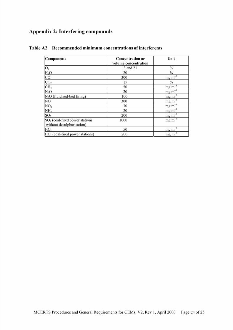
Appendix 2: Interfering compounds
Table A2 Recommended minimum concentrations of interferents
Components Concentration orvolume concentration
Unit
O2 3 and 21 %
H2O 20 %
CO 300 mg m –3
CO2 15 %
CH4 50 mg m –3
N2O 20 mg m –3
N2O (fluidised-bed firing) 100 mg m –3
NO 300 mg m –3
NO2 30 mg m –3
NH3 20 mg m –3
SO2 200 mg m –3
SO2 (coal-fired power stations
without desulphurisation)
1000 mg m –3
HCl 50 mg m –3
HCl (coal-fired power stations) 200 mg m –3

8/10/2019 Continuous Emission Monitoring Systems
http://slidepdf.com/reader/full/continuous-emission-monitoring-systems 31/31
Appendix 3: Standard reference methods
Table A3 Standard reference methods for each determinand. Equivalent national
standards and reference methods may be used as an alternative
Determinand Standard reference method
SO2 ISO 7934 (BS6069 Section 4.1) – Method for the determination of
the mass concentration of sulphur dioxide – hydrogen peroxide/
barium perchlorate/thorium method
BS ISO 11632 – Stationary source emissions – Determination of the
mass concentration of SO2 – Ion chromatography method
USEPA Method 6c, using instruments that meet the MCERTS
performance standards
CO USEPA Method 10, using instruments that meet the MCERTS performance standards
O2 USEPA Method 3a, using instruments that meet the MCERTS
performance standards
NO x BS ISO 11564 – Determination of mass concentration of nitrogen
oxides – Naphthylethylene-diamine photometric method
USEPA Method 7E, using instruments that meet the MCERTS
standards
HCl BSEN 1911-1/2/3 – Manual method for determination of HCl
Particulates ISO 9096 (BS6069 Section 4.3) –
Determination of concentrationand flow rate of particulates material in gas-carrying ducts – manual
gravimetric method
BS EN 13284-1 - Stationary source emissions - Determination of
low range mass concentration of dust - Part 1: Manual gravimetric
method
Flow ISO10780 – Measurement of velocity and volume flow rate of gas
streams in ducts
BS 1042-2.1 – Measurement of fluid flow in closed conduits
Temperature Traceable to the national primary standard
Pressure Traceable to the national primary standard
Water vapour Traceable to the national primary standard