analytical application sets continuous emission monitoring · 2016-09-15 · analytical application...
TRANSCRIPT

4/3Siemens AP 01 · 2016 US Edition
Analytical Application SetsContinuous emission monitoring
Introduction
4
■ Overview
The combustion of different fuels causes not only the develop-ment of carbon dioxide and water vapor but also other environ-mentally harmful exhaust gas substances (e.g. dust, nitrogen oxides and carbon monoxide, etc.) Emission limit values are de-termined for these substances according to the state of combus-tion engineering. The compliance with these limits does not only protect the environment from air pollutants but also ensures op-timum combustion in the combustion plants. Emission measure-ments are a central element for complying with these limit val-ues.
These measurements are required to document whether legal requirements relating to emission limits are complied with. Emis-sion measurements still serve as warranty from plant construc-tors to operators that the plant runs in accordance with the spec-ification and the law.
There are two reasons why the measuring and monitoring of flue gases for emission components is one of the key topics in con-tinuous gas analysis. First, because of the necessity to comply with the legal regulations and directives. Second, because pro-cess plant operators draw conclusions regarding process effi-ciency from the gas analysis, for example, in boiler control.
So called Continuous Emission Monitoring Systems (CEMS) are used for the determination of the exhaust gas components. In Europe, they are usually called Automated Measurements Sys-tems (AMS). DIN EN 15267 determines corresponding minimum requirements and testing procedures for automated monitoring systems for the measurement of gases and particulate sub-stances in the exhaust gas of stationary sources as well as for the measurement of the volume flow of the exhaust gas. It pro-vides detailed procedures for the realization of the requirements for the first quality assurance level (QAL1) of DIN EN 14181 and, if required, the access data for the third quality assurance level (QAL3).
Siemens expertise in the area of products and solutions for process analysis helps you meet all requirements for continuous emission monitoring quickly and smoothly in accordance with regional law. This solution package even ensures a secure investment in case of regulatory adjustments.
According to individual requirements, Siemens offers cold-ex-tractive, hot-extractive, and in-situ automated monitoring sys-tems.
The portfolio is completed by emission evaluation systems for data storage, visualization, remote transmission - permitted ac-cording to TA-Luft, 13., 17., 27., 30. and 31. BImSchV
Siemens does not only offer standard solutions but also com-plete emission analysis systems, e.g. in turnkey analysis con-tainers.
© Siemens AG 2016

4/4 Siemens AP 01 · 2016 US Edition
Analytical Application SetsContinuous emission monitoring
Set CEM CERT
4
■ Overview
Set CEM CERT is a standardized and certified continuous emis-sion monitoring system which is suitable for use in many plants requiring European legislation (13. BImSchV, 17. BImSchV, TA Luft, 2001/80/EC and IED 2010/75/EC, Annex V) approval. The innovative CEMS meets the current quality standards of EU di-rectives EN 14956, EN 15267 and EN 14181 (QAL1/2/3, AST).
■ Benefits
• The tested measuring ranges can be selected for a variety of ranges to ensure use in different areas of application for the CEMS (suitability-tested according to EN 15267-3 (TÜV and MCERTS)).
• The complete modular package allows the certified use of system components from different manufacturers (suitability-tested according to EN 15267-3 (TÜV and MCERTS)).
• Simple and fast to configure• Very low costs of procurement and operation
Modular design• Up to 2 analyzers with different measuring ranges can be
configured• Selection of versions for indoor or outdoor installation• Selection of sample gas cooler and NOX converter from
leading manufacturers• Electric heaters and air conditioners can be configured to
extend the ambient temperature range• Selection of versions with appropriate sampling probes,
heated sample gas lines
■ Application
• Emission monitoring of power plants fueled with solid, gaseous or liquid fuels
• Emission monitoring of so-called TA Luft plants• In plants, where higher concentrations of corrosive aerosols
(acid mist) are formed, precautions need to be taken to remove those out of the gas matrix.In such cases we strongly recommend a project specific technical clarification.
■ Design
Tested component design
The complete system consists of the following tested individual components:• Sampling probe: M&C, type: SP2000; Bühler/Siemens,
type: GAS222/7MB1943-2F• Heated sample gas line: Winkler/Siemens, type: 7MB1943-2A• Temperature controller: Siemens, type: SIRIUS• Two-stage compressor gas cooler: M&C, type: CSS;
Bühler, type: EGK 2-19• Sample gas pump: Bühler/Siemens, type: P2.3/7MB1943-3C• NOX converter: M&C, type: CG-2
Performance-tested measuring ranges
■ Function
The complete tested modular measuring equipment is com-posed of the sampling probe, the heated sample gas line, a two-stage sample gas cooler, a gas pump and the multi-component analyzers, ULTRAMAT 23 and SIPROCESS UV600. An electrochemical or a paramagnetic oxygen measuring cell can be used for the measurement of oxygen.
The gas path splits in parallel after the sample gas cooler. This separately supplies each analyzer with sample gas. One advan-tage for maintenance is that each analyzer can be individually serviced without affecting the other. The sample gas coolers used have a moisture alarm in case of malfunction. For addi-tional protection, each analyzer is protected by a condensation barrier, which stops the gas flow if moisture penetrates. This guarantees optimum protection for gas analyzers.For semi-automatic calibration of the zero and calibration gases, a 3/2-way solenoid valve is installed between the first and sec-ond cooling stages. The valve can also be used for AUTOCAL calibration of the ULTRAMAT 23 (fully automatic timing) as well as by the integrated PLC (LOGO module).
Component Analyzer module
Smallest certi-fied measur-ing range
Additional measuring ranges
CO U23-7MB2355 0 ... 200 mg/m³ 0 ... 750/ 3 000 mg/m³
U23-7MB2357 0 ... 200 mg/m³ 0 ... 750/ 3 000 mg/m³
U23-7MB2358 0 ... 250 mg/m³ 0 ... 1 250 mg/m³
NO U23-7MB2355 0 ... 150 mg/m³ 0 ... 750/ 2 000 mg/m³
U23-7MB2357 0 ... 150 mg/m³ 0 ... 750/ 2 000 mg/m³
U23-7MB2358 0 ... 400 mg/m³ 0 ... 2 000 mg/m³
UV600 0 ... 50 mg/m³ 0 ... 100/ 1 000/2 000 mg/m³
SO2 U23-7MB2355 0 ... 400 mg/m³ 0 ... 2 000 mg/m³
U23-7MB2357 0 ... 400 mg/m³ 0 ... 2 000 mg/m³
U23-7MB2358 0 ... 400 mg/m³ 0 ... 2 000/7 000 (in operation) mg/m³
UV600 0 ... 75 mg/m³ 0 ... 130/1 500/ 2 000 mg/m³
NO2 UV600 0 ... 50 mg/m³ 0 ... 500 mg/m³
O2, (paramag.) U23 0 ... 25 vol %
O2, (electrochem.) U23 0 ... 25 vol %
© Siemens AG 2016
4/5Siemens AP 01 · 2016 US Edition
Analytical Application SetsContinuous emission monitoring
Set CEM CERT
4
■ Technical specifications
1) For NO- and SO2- concentrations >500 mg/m3 the glas heat exchanger shall be used.
2) In case of use of the SIPROCESS UV600 analyzer the cooler typeEGK 2-19 has to be used due to the higher cooling capacity.
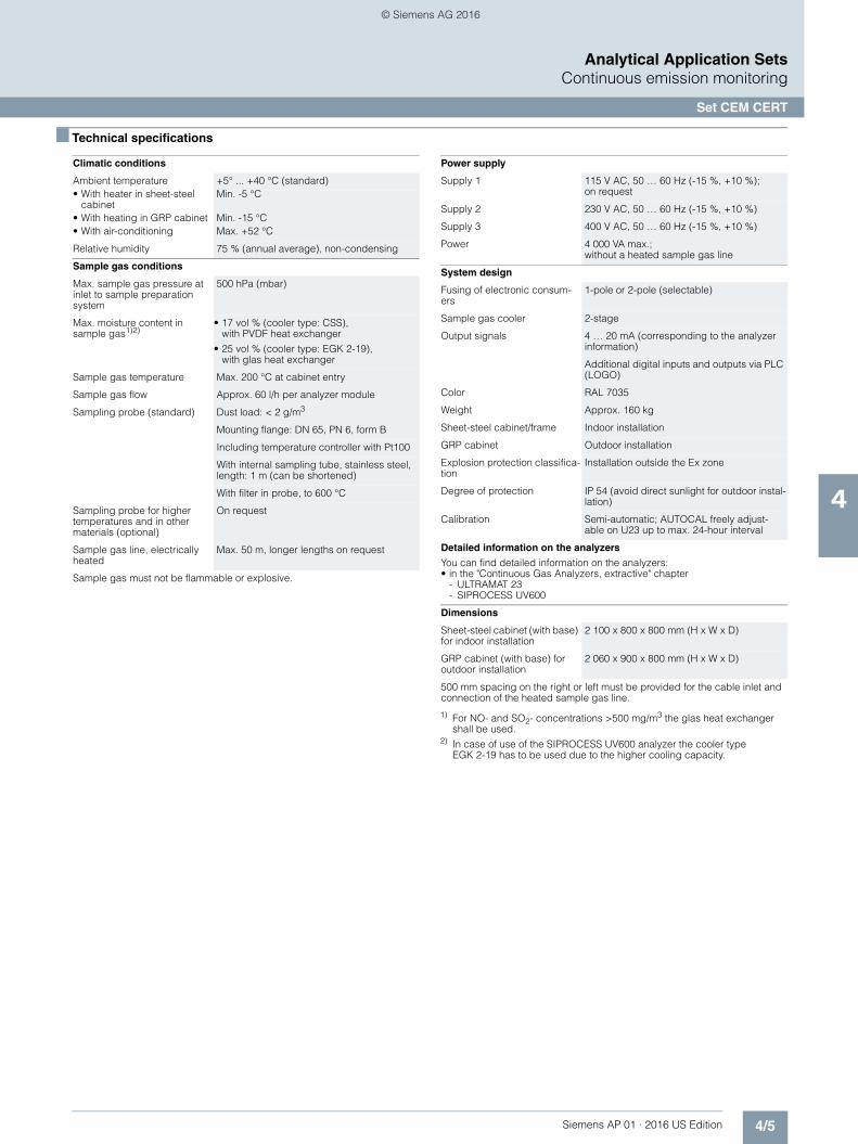
Climatic conditions
Ambient temperature +5° ... +40 °C (standard)• With heater in sheet-steel
cabinetMin. -5 °C
• With heating in GRP cabinet Min. -15 °C• With air-conditioning Max. +52 °C
Relative humidity 75 % (annual average), non-condensing
Sample gas conditions
Max. sample gas pressure at inlet to sample preparation system
500 hPa (mbar)
Max. moisture content insample gas1)2)
• 17 vol % (cooler type: CSS),with PVDF heat exchanger
• 25 vol % (cooler type: EGK 2-19),with glas heat exchanger
Sample gas temperature Max. 200 °C at cabinet entry
Sample gas flow Approx. 60 l/h per analyzer module
Sampling probe (standard) Dust load: < 2 g/m3
Mounting flange: DN 65, PN 6, form B
Including temperature controller with Pt100
With internal sampling tube, stainless steel, length: 1 m (can be shortened)
With filter in probe, to 600 °C
Sampling probe for higher temperatures and in other materials (optional)
On request
Sample gas line, electrically heated
Max. 50 m, longer lengths on request
Sample gas must not be flammable or explosive.
Power supply
Supply 1 115 V AC, 50 … 60 Hz (-15 %, +10 %);on request
Supply 2 230 V AC, 50 … 60 Hz (-15 %, +10 %)
Supply 3 400 V AC, 50 … 60 Hz (-15 %, +10 %)
Power 4 000 VA max.;without a heated sample gas line
System design
Fusing of electronic consum-ers
1-pole or 2-pole (selectable)
Sample gas cooler 2-stage
Output signals 4 … 20 mA (corresponding to the analyzer information)
Additional digital inputs and outputs via PLC (LOGO)
Color RAL 7035
Weight Approx. 160 kg
Sheet-steel cabinet/frame Indoor installation
GRP cabinet Outdoor installation
Explosion protection classifica-tion
Installation outside the Ex zone
Degree of protection IP 54 (avoid direct sunlight for outdoor instal-lation)
Calibration Semi-automatic; AUTOCAL freely adjust-able on U23 up to max. 24-hour interval
Detailed information on the analyzers
You can find detailed information on the analyzers:• in the "Continuous Gas Analyzers, extractive" chapter
- ULTRAMAT 23- SIPROCESS UV600
Dimensions
Sheet-steel cabinet (with base) for indoor installation
2 100 x 800 x 800 mm (H x W x D)
GRP cabinet (with base) for outdoor installation
2 060 x 900 x 800 mm (H x W x D)
500 mm spacing on the right or left must be provided for the cable inlet and connection of the heated sample gas line.
© Siemens AG 2016
4/6 Siemens AP 01 · 2016 US Edition
Analytical Application SetsContinuous emission monitoring
Set CEM CERT
4
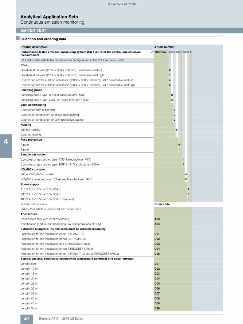
■ Selection and ordering data
Product description Article number
Performance-tested emission measuring system (EN 15267) for the continuous emission measurement
7MB1957- 77777 - 777 0
Click on the Article No. for the online configuration in the PIA Life Cycle Portal.
Rack
Sheet-steel cabinet (2 100 x 800 x 800 mm), hose/cable inlet left 0
Sheet-steel cabinet (2 100 x 800 x 800 mm), hose/cable inlet right 1
Control cabinet for outdoor installation (2 060 x 900 x 800 mm), GRP, hose/cable inlet left 4
Control cabinet for outdoor installation (2 060 x 900 x 800 mm), GRP, hose/cable inlet right 5
Sampling probe
Sampling probe type: SP2000; Manufacturer: M&C B
Sampling probe type: GAS 222; Manufacturer: Bühler C
Ventilation/cooling
Cabinet fan with outlet filter B
Cabinet air conditioner for sheet-steel cabinet C
Cabinet air-conditioner for GRP protective cabinet D
Heating
Without heating 0
Cabinet heating 1
Fuse protection
1-pole 0
2-pole 1
Sample gas cooler
Compressor gas cooler, type: CSS; Manufacturer: M&C 1
Compressor gas cooler, type: EGK 2-19, Manufacturer: Bühler 2
NO2/NO converter
Without NO2/NO converter A
NO2/NO converter, type: CG series; Manufacturer: M&C C
Power supply
115 V AC, -15 %, +10 %, 50 Hz A
230 V AC, -15 %, +10 %, 50 Hz B
400 V AC, -15 %, +10 %, 50 Hz (3-phase) C
Additional versions Order code
Add "-Z" to article number and then order code
Accessories
Condensate tank with level monitoring A03
Acidification module (for measuring low concentrations of SO2) A04
Extractive analyzers, the analyzers must be ordered separately
Preparation for the installation of an ULTRAMAT23 C01
Preparation for the installation of two ULTRAMAT 23 C02
Preparation for the installation of a SIPROCESS UV600 C03
Preparation for the installation of two SIPROCESS UV600 C04
Preparation for the installation of an ULTRAMAT 23 and a SIPROCESS UV600 C05
Sample gas line, electrically heated (with temperature controller and circuit breaker)
Length: 5 m D01
Length: 10 m D02
Length: 15 m D03
Length: 20 m D04
Length: 25 m D05
Length: 30 m D06
Length: 35 m D07
Length: 40 m D08
Length: 45 m D09
Length: 50 m D10
© Siemens AG 2016

4/7Siemens AP 01 · 2016 US Edition
Analytical Application SetsContinuous emission monitoring
Set CEM CERT
4
■ Dimensional drawings
Figure contains options, dimensions in mm
Additional versions Order code
Electronic overcurrent protection for heated sample gas line (only required when heated sample line is not selected from options D01 to D07)
Circuit breaker, 4 A, for lengths up to 5 meters D21
Circuit breaker, 6 A, for lengths up to 10 meters D22
Circuit breaker, 8 A, for lengths up to 15 meters D23
Circuit breaker, 10 A, for lengths up to 20 meters D24
Circuit breaker, 16 A, for lengths up to 30 meters D25
Circuit breaker, 20 A, for lengths up to 35 meters D26
Documentation
German N01
English N02
French N03
Converter (option)
Frontal view hinged frame open
Hinged frame 40HE right stop
Lateral view, left Filter VF1 and VF2 mounted on the back of the device
Heater mounted on the side (option)
Sample gas cooler
Condensate tank (option)Lateral view, right
Air conditioner (option)
Air conditioner (option)
Cable glands electrical input/output
Option
Sample gas inlet
Condensate vent
Zero gas
Sample gas outlet
Calibration gas inlets 1 to 3
Calibration gas U23
VF1
VF2
300
130
800
395
200
2000
100
SIPROCESS UV600
ULTRAMAT 23
© Siemens AG 2016

4/8 Siemens AP 01 · 2016 US Edition
Analytical Application SetsContinuous emission monitoring
Set CEM 1
4
■ Overview
The Set CEM 1 is a standardized system specially for monitoring the emission components in flue gases.
■ Benefits
Standardized complete system• Highly exact and reliable monitoring of emission components
in flue gases. System-specific certificate according to DIN EN ISO 14956 and QAL 1, according to EN 14181 (2004).
• Modular complete package with gas sampling system, sample gas preparation system and gas analyzers from one source
• Simple and fast to configure• Tried and tested, harmonized and reliable set• Low purchase price and economic operation
Proven, suitability-tested technologies• Continuous determination of up to eight measured compo-
nents• In-situ measurements without sampling and preparation,
using LDS 6 laser diode spectrometer• Use of ULTRAMAT 23 with cleanable cells and automatic
calibration with ambient air as well as optional electrochemical oxygen measurement
Optional:• Paramagnetic oxygen measurement with OXYMAT 6
Simple operation• Intuitive operation• Configuration on large displays using plain text, in several
languages
Simple maintenance• Maintenance-friendly cabinet design with hinged frame and
uniform design• Digital display of maintenance requests on LOGO modules
■ Application
The monitoring of emission components in flue gases is one of the most important topics for continuous gas analysis. This is a result of legislation for monitoring emissions, e.g. for large com-bustion plants, and also due to the requirements of companies operating process plants who can draw conclusions on the pro-cess efficiency from the gas analyses, e.g. with boiler control, DENOX and DESOX plants.
The market requires a reliable complete system which is spe-cially designed for the application. The Set CEM 1 (Continuous Emission Monitoring) offered by Siemens is a system which reli-ably covers all requirements associated with sampling, sample preparation, and gas analysis.
It is possible to determine the concentrations of the gaseous components CO, CO2, NO, NOx, SO2, O2, Ctotal, HCl, HF, NH3 and H2O.
The ULTRAMAT 23 and OXYMAT 6 are used for the extractive, continuous gas analysis.
The standardized Set CEM 1 provides great clarity and simple configuration facilities. Different versions mean that it is possible to appropriately adapt the system to the requirements. Stan-dardization also means that not all imaginable versions can be included, and that it may not be possible to implement special requirements such as armored cables, varying gas composi-tions, customer-specific documentation or specific conductor la-beling without an extra charge.
■ Design
Starting with a mounting frame with sample preparation system, it is possible to add additional units as options. These include:• Sampling probe with weather protection hood• Heated sample gas line (for details see catalog PA11)• Analyzers• Air-conditioning unit• NO2/NO converter• Sample preparation extension for an additional ULTRAMAT 23
analyzer• Single and dual (electrically isolated, not electrically isolated)
analog signal processing• Power supply modules (115 V, 230 V, 400 V)• Outer panels with steel-plate door or with window• Single-pole and double-pole fusing• Condensation bottle• Coalescence filter
Sampling probe
The standard probe is fitted with a DIN flange DN 65, PN 6. The probe is provided with a regulated heater, and has a power con-sumption of 400 VA. It is supplied with a weather protection hood and 2 µm filter. The maximum dust concentration at the sampling point should not exceed 2 g/m³. The sampling pipe is 1 000 mm long, is made of stainless steel, and has dimensions of 20 x 1.5 mm. The sample gas temperature must not exceed 600 °C.
It is also possible to purchase the Set CEM 1 without sample probe.
© Siemens AG 2016

4/9Siemens AP 01 · 2016 US Edition
Analytical Application SetsContinuous emission monitoring
Set CEM 1
4
Heated sample gas line
The temperature of the heated line is regulated at 200 °C by a temperature controller. The power consumption is 100 VA per meter. The internal core is made of PTFE 4/6. The heated line can be up to 35 m in length. Lengths greater than 35 m can be pro-vided upon special request. If desired, the system can also be supplied without a heated sample gas line.
Mounting frame
The basis of each CEM 1 set is the mounting frame with hinged frame (40 HU) for installation of up to five 19" rack units. The mounting frame includes a standardized sample preparation system designed for an ULTRAMAT 23.
The sample preparation system includes a 3/2-way solenoid valve, 3-way switchover ball valve, regulating valve, corrosion-resistant sample gas pump (power consumption 60 VA), con-densation trap, room air suction filter with filter element, LOGO for digital display of individual signals in the cabinet, 24 V DC power supply unit (power consumption 70 VA). Also included are a sample gas cooler (power consumption 200 VA) with inte-gral heat exchanger, hose pump, moisture sensor with flow cell and Teflon filter. Teflon tubes connect the components.
The external dimensions without plinth are 2 000 x 800 x 800 mm (H x W x D). A cabinet depth of 600 mm is also optionally avail-able (not suitable for LDS 6). Hoses and cables can be con-nected from the left or right. A distance of 500 mm must be pro-vided on the left or right at the installation site for introduction of the hoses and cables.
In addition to the sheet-steel mounting frames for indoor installa-tion, an FRP version is also available for outdoor use. The FRP cabinet is always provided complete with side panels and plinth. The external dimensions are 2 080 x 800 x 600 mm (H x W x D). The GRP cabinet cannot be combined with the LDS 6.
Preparation of sample preparation system for second ULTRAMAT 23
The standard system with sample preparation system and elec-tronics is prepared for one ULTRAMAT 23. If a second ULTRAMAT 23 is to be fitted, this option must be selected so that the sample preparation system and electronics are extended ac-cordingly.
Additional filter
In addition to the fine filter and moisture filter which are always present, a coalescence filter can be optionally fitted in the sam-ple preparation system.
Side panels with doors
Optional outer panels can be selected for the sheet-steel mount-ing frames. This possibility allows use of the CEM 1 set in analy-sis cabinets as a rack design on one hand, or on the other as a cabinet design in halls requiring degree of protection IP54. Ei-ther a sheet-steel door without window or a glass door can be selected.
Base
Plinths with a height of 100 and 200 mm are additionally avail-able.
Cabinet cooling and ventilation
Optionally available are a fan with outlet filter, an air-conditioning unit for indoor installation, and an air-conditioning unit for out-door installation. The system can be ordered without a fan or air-conditioning unit if the side panels and the door with window are omitted.
The fan with outlet filter has a power consumption of 60 VA, and is fitted in the cabinet wall. The delivery also includes a thermo-stat with a power consumption of 25 VA.
The air-conditioning unit has a cooling power of 820 VA.
Frost protection heater
The power consumption of the optional cabinet heater is 500 VA. The delivery includes a thermostat with a power consumption of 25 VA for controlling the frost protection heater.
Fusing of the analog signals
In addition to single-pole fusing of the electronic consumers, it is possible to provide double-pole fusing.
The double-pole fuse is mainly required in Benelux countries.
Removal of condensation
A 19 liter condensation bottle can be provided as an option. It is also possible to order the system without a condensation bottle if the condensation can be removed on-site.
NO2/NO converter
The mounting frame and cabinets can be optionally extended by a 19" rack unit with NO2/NO converter with carbon cartridge. The power consumption is 520 VA. The flow rate is 90 l/h. An NO2/NO converter is required if the share of NO2 in the total NOx is greater than 5 % and/or if total NOx is to be always determined.
Power supply
The system can be designed either for 115 V AC, 230 V AC or 400 V AC (-15 %, +10 %) with 50 or 60 Hz.
Three phases, neutral and ground must be provided by the cus-tomer at 400 V AC.
Analog signal processing
As standard, the analog signals are simply connected to isolat-ing terminals. As an option, the analog signals can be pro-cessed twice without electrical isolation by a diode module, or twice with electrical isolation.
Analyzers
The standardized set is prepared for an ULTRAMAT 23. The sys-tem can be supplemented by a second ULTRAMAT 23, OXYMAT 6 and/or LDS 6. Various measured components and measuring ranges can be selected. Other combinations of mea-sured components and measuring ranges are available on re-quest, but you must check that the desired certificates and ap-provals are available. The analyzers, measured components and measuring ranges used are described briefly below.
Details on the analyzers, alternative components and ranges can be found under the topics "Continuous gas analyzers, ex-tractive" and "Continuous gas analyzers, in-situ".
ULTRAMAT 23: CO, NO
For measuring two infrared components.
One or two measuring ranges can be freely set within the limits. The ULTRAMAT 23 carries out automatic self-calibration with ambient air. The power consumption is 60 VA.
Component Smallest tested measuring range
Switchable to
CO 0 ... 150 mg/Nm³ 0 ... 750 mg/Nm³
NO 0 ... 100 mg/Nm³ 0 ... 500 mg/Nm³
© Siemens AG 2016

4/10 Siemens AP 01 · 2016 US Edition
Analytical Application SetsContinuous emission monitoring
Set CEM 1
4
ULTRAMAT 23: CO, NO, SO2
For measuring three infrared components.
One or two measuring ranges can be freely set within the limits. The ULTRAMAT 23 carries out automatic self-calibration with ambient air. The power consumption is 60 VA.
ULTRAMAT 23: CO, NO, CO2
For measuring three infrared components.
One or two measuring ranges can be freely set within the limits. The ULTRAMAT 23 carries out automatic self-calibration with ambient air. The power consumption is 60 VA.
The component CO2 has not been type approved by the TÜV.
ULTRAMAT 23: CO2
For measuring one infrared component.
One or two limits can be freely set within the limits. The ULTRA-MAT 23 carries out automatic self-calibration with ambient air. The power consumption is 60 VA.
The component CO2 has not been type approved by the TÜV.
The ULTRAMAT 23 analyzers can be optionally equipped with an electrochemical oxygen sensor.
O2: Tested measuring ranges 0 to 10/25 %
OXYMAT 6: O2
For paramagnetic measurement of oxygen. Instead of ULTRAMAT 23 with electrochemical cell.
O2: Tested measuring ranges 0 to 10/0 to 25 %
Sample chamber without flow-type compensation branch, made of stainless steel 1.4571.
LDS 6: HCl
Application for channel 1: Emission monitoring
The power consumption is 50 VA. Suitable for connection of non-Ex sensors, including non-Ex-protected sensor electronics.
The delivery includes a pair of sensors for instrument air or N2 on the process side. The pair of sensors is designed for a moderate flow rate of 0 to 120 l/min. The 400 mm long purging tubes are made of stainless steel. The process connection is DN 65, PN 6. The power consumption is 2 VA.
Limitation:Applies to measurement paths > 2 000 mm, applies to gases with a methane content < 15 mg/m³. Necessary gas temperature between 120 and 210 °C.
LDS 6: HCl / H2O
Application for channel 1: Emission monitoring
The power consumption is 50 VA. Suitable for connection of non-Ex sensors, including non-Ex-protected sensor electronics.
The delivery includes a pair of sensors for instrument air or N2 on the process side. The pair of sensors is designed for a moderate flow rate of 0 to 120 l/min. The 400 mm long purging tubes are made of stainless steel. The process connection is DN 65, PN 6. The power consumption is 2 VA.
Limitation:Applies to measurement paths > 2 000 mm, applies to gases with a methane content < 15 mg/m³. Necessary gas temperature between 120 and 210 °C.
LDS 6: HF
HF: Smallest possible measuring range depends on the gas composition.
Application for channel 1: Emission monitoring
The power consumption is 50 VA. Suitable for connection of non-Ex sensors, including non-Ex-protected sensor electronics.
The delivery includes a pair of sensors for instrument air or N2 on the process side. The pair of sensors is designed for a moderate flow rate of 0 to 120 l/min. The 400 mm long purging tubes are made of stainless steel. The process connection is DN 65, PN 6. The power consumption is 2 VA. The HF measurement has not been type approved by the TÜV.
Limitation:Component has not been type approved by TÜV. Necessary gas temperature between 0 and 150 °C.
LDS 6: HF/H2O
HF: Smallest possible measuring range depends on the gas composition.
H2O: Smallest tested measuring range 0 to 30 %
Application for channel 1: Emission monitoring
The power consumption is 50 VA. Suitable for connection of non-Ex sensors, including non-Ex-protected sensor electronics.
The delivery includes a pair of sensors for instrument air or N2 on the process side. The pair of sensors is designed for a moderate flow rate of 0 to 120 l/min. The 400 mm long purging tubes are made of stainless steel. The process connection is DN 65, PN 6. The power consumption is 2 VA. The HF measurement has not been type approved by the TÜV.
Limitation:Component has not been type approved by TÜV. Necessary gas temperature between 0 and 150 °C.
Component Smallest tested measuring range
Switchable to
CO 0 ... 250 mg/Nm³ 0 ... 1 250 mg/Nm³
NO 0 ... 400 mg/Nm³ 0 ... 2 000 mg/Nm³
SO2 0 ... 400 mg/Nm³ 0 ... 2 000 mg/Nm³
Component Smallest tested measuring range
Switchable to
CO 0 ... 250 mg/Nm³ 0 ... 1 250 mg/Nm³
NO 0 ... 400 mg/Nm³ 0 ... 2 000 mg/Nm³
CO2 0 ... 5 % 0 ... 25 %
Component Smallest measuring range Largest measuring range
CO2 0 ... 5 % 0 ... 25 %
Component Smallest tested measuring range
HCl 0 ... 15 mg/Nm³
Component Smallest tested measuring range
HCl 0 ... 15 mg/Nm³
H2O 0 ... 30 %
© Siemens AG 2016

4/11Siemens AP 01 · 2016 US Edition
Analytical Application SetsContinuous emission monitoring
Set CEM 1
4
LDS 6: NH3
Application for channel 1: Emission monitoring
The power consumption is 50 VA. Suitable for connection of non-Ex sensors, including non-Ex-protected sensor electronics.
The delivery includes a pair of sensors for instrument air or N2 on the process side. The pair of sensors is designed for a moderate flow rate of 0 to 120 l/min. The 400 mm long purging tubes are made of stainless steel. The process connection is DN 65, PN 6. The power consumption is 2 VA.
Limitation:Applies to measurement paths > 1 250 mm. Necessary gas tem-perature between 0 and 150 °C.
LDS 6: NH3/ H2O
Application for channel 1: Emission monitoring
The power consumption is 50 VA. Suitable for connection of non-Ex sensors, including non-Ex-protected sensor electronics.
The delivery includes a pair of sensors for instrument air or N2 on the process side. The pair of sensors is designed for a moderate flow rate of 0 to 120 l/min. The 400 mm long purging tubes are made of stainless steel. The process connection is DN 65, PN 6. The power consumption is 2 VA.
Limitation:Applies to measurement paths > 1 250 mm. Necessary gas tem-perature between 0 and 150 °C.
Hybrid cable
A hybrid cable is required to connect a central unit to one pair of sensors. Versions for 5, 10, 25, 40 and 50 m are available. Cable lengths cannot be combined. Lengths greater than 50 m can be ordered on request.
Sensor cable
A sensor cable is required to connect one pair of sensors. Ver-sions for 5, 10 and 25 m are available. Cable lengths cannot be combined. Lengths greater than 25 m can be ordered on re-quest.
Electrical preparation for dust measurement
Electrical preparation for connection of an external dust mea-surement to the system (contains a switch amplifier).
Electrical preparation for flow measurement
Electrical preparation for connection of an external flow mea-surement to the system (contains a switch amplifier).
Electrical preparation for pressure measurement
Electrical preparation for connection of an external pressure measurement to the system (contains a switch amplifier).
Electrical preparation for temperature measurement
Electrical preparation for connection of an external temperature measurement to the system (contains a switch amplifier).
Electrical preparation for emission data memory on rail module
On request.
Electrical preparation for emission data memory in 19" rack unit
On request.
Additional LOGO for four or more 19" rack units
Sets with more than three 19" rack units integrated require a LOGO extension module. The delivery also includes connection and programming.
Core end labeling
It is optionally possible to order core end labeling according to the Siemens standard (VDE 0100 Part 200).
Documentation
The Siemens standard documentation is available in German or English.
The documentation includes gas path diagram, circuit diagram, terminal diagram, installation diagram, consumable materials list, signal list, cable list, and parts list. Also included are techni-cal data sheets and Operating Instructions for the components and devices used. The documentation language for parts pro-vided by other suppliers may deviate. Plant description, LOGO program and test certificates are also included in the documen-tation.
The documentation contains no customer-specific/project-spe-cific drawings, and consists of two folders and one CD per set.
Component Smallest tested measuring range
NH3 0 ... 20 mg/Nm³
Component Smallest tested measuring range
NH3 0 ... 20 mg/Nm³
H2O 0 ... 15 %
© Siemens AG 2016

4/12 Siemens AP 01 · 2016 US Edition
Analytical Application SetsContinuous emission monitoring
Set CEM 1
4
Set CEM 1, gas flow chart, figure contains options
U23
CO/NO
SO2
NOCLF
O2
HCL,H2O
U23
O6E
LDS 6
LDS 6
LOGO TD
Option
Option
Option
Option
Option
Option
Calibration gas inlet
Sample gas inlet
L = max. 35 m
Measuring equipment
Sample gas outlet
2nd ULTRAMAT 23 (option)
OXYMAT 6E (option)
LDS 6 (option)
Cabinet heating(option)
Converter Water trap
Cabinet ventilation (option)Optional
Fan/outlet filteror air-conditioning unit
19 liters
© Siemens AG 2016

4/13Siemens AP 01 · 2016 US Edition
Analytical Application SetsContinuous emission monitoring
Set CEM 1
4
■ Function
A sample is extracted via the heated sample gas probe. The dust concentration may be up to 2 g/m³, the sample gas tem-perature up to 600 °C. The gas is transported to the analysis cabinet via a heated sample gas line. The heating prevents con-densate. The gas cooler cools and dries the sample in the anal-ysis cabinet. Condensate is drained. The level in the condensate trap is monitored. For safety purposes, a coalescence filter can be provided in addition to the fine filter and moisture filter which are always present. The sample gas is analyzed by analyzers such as the ULTRAMAT 23, OXYMAT 6 and LDS 6. The ULTRA-MAT 23 operates on the basis of molecular-specific absorption of infrared radiation or with an electrochemical oxygen measur-ing cell. The OXYMAT 6 is an analyzer for paramagnetic oxygen measurements. The in-situ LDS 6 laser diode spectrometer op-erates according to the molecular-specific absorption of near-IR radiation. The delivery may also include an NO2/NO converter which permits measurement of total nitrogen oxides. In order to qualify the set for low or high temperature ranges (-5, +45 °C), it is possible to use a cabinet heater or air-conditioning unit. Power supply versions are available for 115, 230 or 400 V AC. Elec-tronic consumers can be provided with single-pole or double-pole fusing. The components of the sample preparation system and the analyzers are connected to LOGO modules via a binary signal, and transmit maintenance requirements. The analog sig-nals can be processed either singly or twice. Electrical isolation is additionally possible for the double processing.
■ Technical specifications
It is necessary to provide a 500 mm gap to the right or left for the tube or cable inlet.Use of the LDS 6 requires a cabinet with a depth of 800 mm.1) Higher performance sample gas coolers can be offered upon request (not
TÜV suitability-tested). A higher performance cooler is generally required for high sulfide content in fuels (e.g. heavy oil).
Climatic conditions
Ambient temperature 0 ... 35 °C• With heater in sheet-steel cabinet Min. -5 °C• With heating in GRP cabinet Min. -15 °C• With air-conditioning Max. 52 °C
Relative humidity 70 %, non-condensing
Corrosive atmosphere No
Gas inlet conditions
Max. sample gas pressure at inlet to sample preparation system
500 hPa (mbar)
Max. moisture content in sample gas 17 vol-% 1)
Max. water dew point 60 ?
Min. sample gas pressure at inlet to sample preparation system
180 °C
Dust content at inlet to sample prepa-ration system
Dust-free
Sampling probe Sampling tube 20 x 1.5, 1 000 mm long, stainless steel, flange: DN 65, PN 6
Max. sample gas pressure at sam-pling probe
500 hPa (mbar)
Max. sample gas temperature at sam-pling probe
600 °C
Max. dust content at sampling probe 2 g/Nm³
Sample gas must not be flammable or explosive.
Power supply
Supply 1 115 V AC (-15 %, +10 %)
Supply 2 230 V AC (-15 %, +10 %)
Supply 3 400 V AC (-15 %, +10 %)
Connections
Hose material Teflon
Cables Not armored, not halogen-free
Electrical design According to IEC
Cable ID Individual core labeling as option
Fusing of electronic consumers 1-pole; 2-pole as option
Duplication of analog signals • Not electrically isolated as option• Electrically isolated as option
Installation
Site• In sheet-steel cabinet/frame Indoor installation• In GRP cabinet Outdoor installation
Ex zone Non-Ex area
System design
Type Mounting frame or cabinet
Cabinet degree of protection IP54
Automatic calibration Yes, with ULTRAMAT 23
Detailed information on the analyzers
You can find detailed information on the analyzers:• In the "Continuous Gas Analyzers, extractive" chapter
- ULTRAMAT 23- OXYMAT 6
• In the "Continuous Gas Analyzers, in-situ" Chapter - LDS 6
Dimensions (without plinth)
Depth of sheet-steel frame• 800 mm (without plinth) 2 000 x 800 x 800 mm (H x W x D)• 600 mm (without plinth) 2 000 x 800 x 600 mm (H x W x D)
GRP cabinet (with plinth) 2 080 x 900 x 600 mm (H x W x D)
© Siemens AG 2016

4/14 Siemens AP 01 · 2016 US Edition
Analytical Application SetsContinuous emission monitoring
Set CEM 1
4
Selection and ordering data Article No.
Set CEM 1 – Continuous Emission Monitoring 7MB1953- 77777 - 777 7 Cannot be combined
Click on the Article No. for the online configuration in the PIA Life Cycle Portal.
Rack
Rack 1: 2 000 x 800 x 800 mm (H x W x D), with sample preparation device, with hinged frame 40 HU, hose/cable inlet on left side, with lighting, preparedfor 1 x ULTRAMAT 23, max. five 19" rack units possible
0 A03, A04, B02, B04
Rack 2: 2 000 x 800 x 800 mm (H x W x D), with sample preparation device, with hinged frame 40 HU, hose/cable inlet on right side, with lighting, preparedfor 1 x ULTRAMAT 23, max. five 19" rack units possible
1 A03, A04, B02, B04
Rack 3: 2 000 x 800 x 600 mm (H x W x D), with sample preparation device, with hinged frame 40 HU, hose/cable inlet on left side, with lighting, preparedfor 1 x ULTRAMAT 23, max. five 19" rack units possible, not suitable for LDS 6
2 A01, A02, B01, B03, E01 ... E06, F01 ... F06,G01 ... G04
Rack 4: 2 000 x 800 x 600 mm (H x W x D), with sample preparation device, with hinged frame 40 HU, hose/cable inlet on right side, with lighting, preparedfor 1 x ULTRAMAT 23, max. five 19" rack units possible, not suitable for LDS 6
3 A01, A02, B01, B03, E01 ... E06, F01 ... F06,G01 ... G04
Rack 5: 2 060 x 900 x 600 mm (H x W x D), GRP, base 80 mm, with sample prepara-tion device, with hinged frame 40 HU, hose/cable inlet on left side, with lighting, pre-pared for 1 x ULTRAMAT 23, with side panels, incl. door with window, max. five 19" rack units possible, not suitable for LDS 6
4 A01 ... A04, B01 ... B04, E01 ... E06, F01 ... F06,G01 ... G04
Rack 6: 2 060 x 900 x 600 mm (H x W x D), GRP, base 80 mm, with sample prepara-tion device, with hinged frame 40 HU, hose/cable inlet on right side, with lighting, prepared for 1 x ULTRAMAT 23, with side panels, incl. door with window, max. five 19" rack units possible, not suitable for LDS 6
5 A01 ... A04, B01 ... B04, E01 ... E06, F01 ... F06,G01 ... G04
Sampling probe
Without A
Standard sampling probe B
Ventilation/cooling
Without A
Fan with outlet filter B
Cabinet air-conditioning unit C
Cabinet air-conditioning unit for GRP rack D
Heating
Without 0
Cabinet heating 1
Fuse protection
1-pole 0
2-pole 1
Removal of condensation
Without 0
19 l container with level monitoring 1
NO2/NO converter
Without A
NO2/NO converter B
Power supply
115 V AC, -15 %, +10 %, 50 or 60 Hz A
230 V AC, -15 %, +10 %, 50 or 60 Hz B
400 V AC, -15 %, +10 %, 50 or 60 Hz (3 phases, neutral, ground provided by customer)
C
Connection set for heated line
Without controller 0
Standard controller (max. 35 m heated line can be connected) 1
Note:The heated sample gas line must be ordered separately using Catalog PA 11.
© Siemens AG 2016

4/15Siemens AP 01 · 2016 US Edition
Analytical Application SetsContinuous emission monitoring
Set CEM 1
4
Additional versions Order code
Add "-Z" to Article No. and specify Order code
Bases
Base for rack 1, 2, height 100 mm A01
Base for rack 1, 2, height 200 mm A02
Base for rack 3, 4, height 100 mm A03
Base for rack 3, 4, height 200 mm A04
Rack accessories
Outer panel painted, for rack 1 and 2, viewing door B01
Outer panel painted, for rack 3 and 4, viewing door B02
Outer panel painted, for rack 1 and 2, sheet steel door B03
Outer panel painted, for rack 3 and 4, sheet steel door B04
ULTRAMAT 23, OXYMAT 6 extractive analyzers
ULTRAMAT 23: CO, NO C01
ULTRAMAT 23: CO, NO, SO2 C02
ULTRAMAT 23: CO, NO, CO2 C03
ULTRAMAT 23: CO2 C04
ULTRAMAT 23: Electrochemical O2 sensor for ULTRAMAT 23 expansion C05
OXYMAT 6: OXYMAT paramagnetic O2 analyzer C06
Preperation for free choice ULTRAMAT 23 analyzer C07
Additional sample preparation components
Coalescence filter D02
LDS 6 in-situ analyzers
HCl including sensor pair E01
HCl/H2O including sensor pair E02
HF including sensor pair, not suitability-tested E03
HF/H2O including sensor pair, not suitability-tested E04
NH3 including sensor pair E05
NH3/H2O including sensor pair E06
LDS 6 hybrid cable per LDS 6
5 m F01
10 m F02
25 m F03
40 m F04
50 m F05
Customer-specific > 50 m F06
LDS 6 connecting cable per LDS 6
5 m G01
10 m G02
25 m G03
Customer-specific > 25 m G04
Electrical preparation
Preparation for dust measurement J01
Preparation for flow measurement J02
Preparation for pressure measurement J03
Preparation for temperature measurement J04
Preparation for emission data memory – DIN rail module (on request) J05
Preparation for emission data memory – 19" rack unit (on request) J06
Additional LOGO
LOGO for a third and fourth 19" rack unit K01
© Siemens AG 2016

4/16 Siemens AP 01 · 2016 US Edition
Analytical Application SetsContinuous emission monitoring
Set CEM 1
4
■ Dimensional drawings
Design of the Set CEM 1, figure contains options, dimensions in mm
Core end labeling
Single-core labeling Siemens standard L01
Analog signal processing
Double, galvanically connected, 1 x per analog signal M01
Double, galvanically isolated, 1 x per analog signal M02
Documentation
German N01
English N02
French (on request) N03
Additional versions Order code
ULTRAMAT 23ULTRAMAT 23
SIEMENSSIEMENS
0.000.000.000.00
+ -
ULTRAMAT 23ULTRAMAT 23
SIEMENSSIEMENS
0.000.000.000.00
ULTRAMAT 23ULTRAMAT 23
Siemens
SiemensSiemens
-RV3OXYMAT 6EOXYMAT 6E
LDS 6E
SIEMENSSIEMENSs LOGO! TD
800
2000
100 35
0
ULTRAMAT 23ULTRAMAT 23
Sample gas inlet
Sample gas outlet
Spare
Electricalinput/output
Front viewHinged frame open
Hinged frame 40 HU
Side view from leftSide view from right
Condensation outlet
Spare location
Spare locationfor converter(option)
Control cabinet ventilation (when using side walls) **Either fan and outlet filteror air-conditioning unitMounting on left or right
Option:Electronic and pneumaticinputs and outputseither on left or right
Outlet filter
Fan
Option:Coalescence filter
Option:Analog signalduplicationwith electricalisolation
Option:Cabinet heater
Standard: voltage 230 V/50 Hz, 1-pole fusingOption:voltage 115 V/50 Hz / 400 V/50 Hz, 2-pole fusing
Standard: without plinthOption:with plinth 100 or 200 mm high
Available cabinet sizes:Metal: W x H x D: 800 x 2 000 x 600Metal: W x H x D: 800 x 2 000 x 800FRP: W x H x D: 900 x 2 140 x 600** FRP cabinet is always with side walls and 80 mm plinth
Option:condensation bottlewith level monitoring19 liters
LOGOOptionally extendableDepends on numberof analyzers.
Option:
Calibration gas inlet
Sample gas cooler
2. ULTRAMAT 23 (option)
OXYMAT 6E (option)
LDS 6E (option)
© Siemens AG 2016
4/17Siemens AP 01 · 2016 US Edition
Analytical Application SetsContinuous emission monitoring
HM-1400 TRX Total mercury analyzer system
4
■ Overview
The HM-1400 TRX is a total mercury monitor for fully automatic and continuous measurement of emissions of mercury in flue gas ducts.
■ Benefits
• Extractive measuring procedure• Low maintenance dry reactor• High operational reliability• Easy maintenance, easy replacement of components• Low cross sensitivities• Easy to read LC display
■ Application
The HM-1400 TRX monitors not only the performance of the mer-cury separators by measuring the total mercury concentration, but also reports and registers (also online) any violation of the high limits. As a result it is often possible to intervene directly in the process of the plant to be monitored and thus ensure reliable compliance with the specified limit values.
Areas of application• Waste incineration plants (municipal waste, industrial waste,
hospital waste)• Sewage sludge and hazardous waste incineration• Steel plants with scrap metal preparation• Contaminated soil burning plants (thermal cleanup of soil)• Crematoriums• Mercury mines and refineries• Fluorescent light bulb recycling
Approvals• Suitability-tested by the TÜV North, test report 109 GMT007/
8000632287 dated 30 June 2011• Certified according to DIN EN 15267-3• Itemized in the list of suitable measuring devices for
continuous emission measuring• MCERTS
■ Design
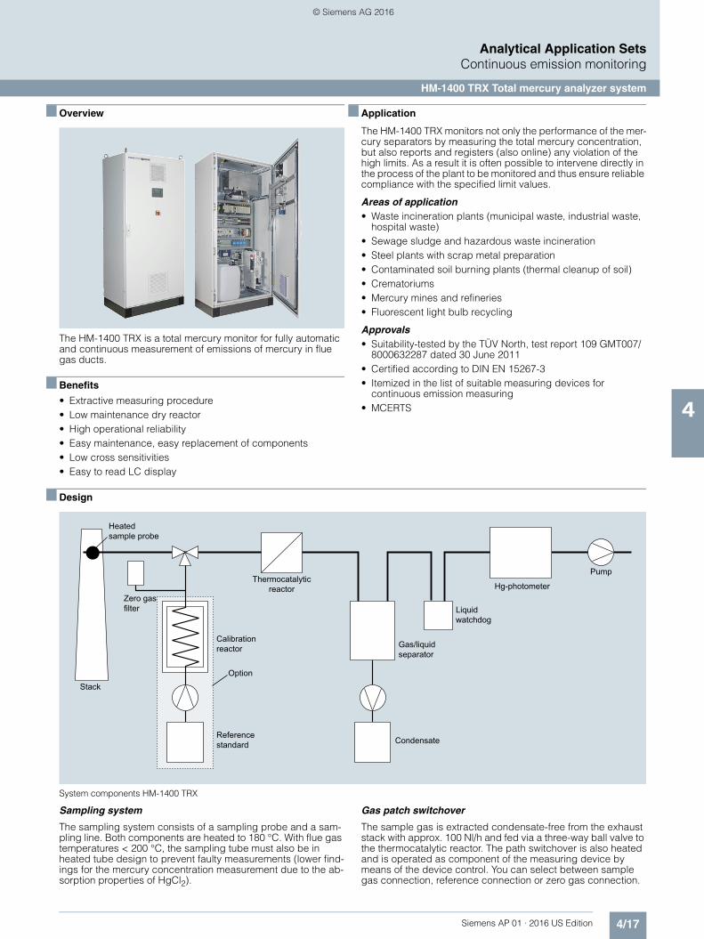
System components HM-1400 TRX
Sampling system
The sampling system consists of a sampling probe and a sam-pling line. Both components are heated to 180 °C. With flue gas temperatures < 200 °C, the sampling tube must also be in heated tube design to prevent faulty measurements (lower find-ings for the mercury concentration measurement due to the ab-sorption properties of HgCl2).
Gas patch switchover
The sample gas is extracted condensate-free from the exhaust stack with approx. 100 Nl/h and fed via a three-way ball valve to the thermocatalytic reactor. The path switchover is also heated and is operated as component of the measuring device by means of the device control. You can select between sample gas connection, reference connection or zero gas connection.
Pump
Liquid watchdog
Reference standard Condensate
Gas/liquid separator
Hg-photometer
Option
Calibration reactor
Stack
Heated sample probe
Zero gas filter
Thermocatalytic reactor
© Siemens AG 2016

4/18 Siemens AP 01 · 2016 US Edition
Analytical Application SetsContinuous emission monitoring
HM-1400 TRX Total mercury analyzer system
4
Thermocatalytic reactor
The total mercury analysis measures not only the elementary metallic mercury that is stored freely in the sample gas or depos-ited in the materials, but also measures the chemically bonded mercury that is found in the flue gas. The ionic mercury must also be converted into elementary, atomic mercury so that the detec-tor can acquire and evaluate the total mercury. The thermocata-lytic reactor carries out this function at a pre-set operating tem-perature.
Gas drying
Before the mercury content is determined, the now created sam-ple gas containing Hg0 is dried while flowing through a Peltier cooler. At the same time the system pressure and the measured gas temperature are continuously recorded.
Prefilter
Before the prepared and dried sample gas flows through the photometer, it passes through an additional filter with hygro-scopic effect to eliminate even lower residual humidity compo-nents. This is important first for recording the gas volume flow in dry form and, second, pollution and deposits are avoided in the photometer and the maintenance-free service life increased.
2-beam UV photometer
The sample gas enters the measuring cuvette and is then routed over a selective filter in which the mercury is absorbed. The sam-ple gas thus freed from the mercury then flows through the refer-ence cuvette. The advantage of this cuvette switching is that the entire gas matrix flows through both the measuring cuvette and the reference cuvette and most of the mercury is selectively fil-tered out before it reaches the reference cuvette. This principle of differential measurement means that the measurement is less sensitive to spectrometric interference components than the sin-gle-beam photometer that has only one cuvette. With the cuvette switching of the two-beam device this cross sensitivity for SO2, for example, only becomes effective after 1000 mg/m³. The mea-sured signal from the photometer is taken over by the internal PLC.
Gas volume flow generation
When the sample gas volume flow leaves the 2-beam UV pho-tometer, it passes through the vacuum pump which generates the gas flow. The volume flow of approx. 100 Nl/h is set manually with the fine regulating valve. The system pressure and sample gas temperature parameters are measured after the gas drying at the photometer, where the mercury is also measured, and are used ultimately to convert the gas volume flow to standard con-ditions. The mercury concentration as result of a measurement is output as 4 to 20 mA current signal to match the set measuring range of 0 to X µg/Nm3 (dry).
Optional:• Larger measuring range with dilution device• Side-mounted cooling device• Integrated system to generate reference gas• Heated sample pipe 0.6 m, 1.0 m, 1.5 m
■ Function
In the HM 1400 TRX total mercury analyzer the sample gas is converted into mercury vapor by a combination of thermal and chemical treatment. It is then continuously measured in a pho-tometer. The sample gas flow is measured after a sample game cooler at 2 °C. The concentration is calculated and displayed as "dry flue gas".
■ Technical specifications
■ More information
A HM-1400 TRX total mercury analyzer consists of, for example:• 1 sampling pipe, heated and temperature-controlled, with
connecting cable• 1 sampling probe, heated and temperature-controlled, with
connecting cable• 1 sampling line, heated and temperature-controlled• 1 measuring device • Operating instructions, service manual, maintenance manual
Please consult your Siemens sales partner for information on how to correctly configure and order a HM-1400 TRX total mer-cury analyzer for a Siemens CEMS project.
Measured variable Total mercury
Measuring ranges 0 ... 45, 0 ... 75 to 0 ... 500 g/Nm3
Measuring principle UV absorption
Sample gas temperature 0 ... 250 °C
Sample gas pressure -50 ... +50 hPa
Duct diameter > 0.5 m
Ambient temperature 5 °C ... 40 °C
Degree of protection IP40 (IP54)
Measured value outputs 2 x 0/4 ... 20 mA, 500
Relative expanded uncertainty 5.5 % CR
Digital outputs 4 relay outputs, permissible load 250 V, 100 VA
Digital inputs 1 isolated input
Detection limit < 0.1 g/Nm3
Reference point drift < 2 % ZRE
Zero point drift < 0.5 % ZREautomatic zero offset
Supply voltage 230/400 V AC, 50 Hz, 3 x L, N, PE• Measuring instrument 1200 VA• Sampling probe 650 VA• Sampling line 100 VA/m• Heated sample pipe 0.6 m, 1.0 m,
1.5 m 600 VA/800 VA/1200 VA
Dimensions (H x W x D) control cabi-net
1700 x 800 x 500 mm
Weight 220 kg
Purge air supply, compressed air 6 ... 8 bar (for reference gas genera-tor only)
© Siemens AG 2016

4/19Siemens AP 01 · 2016 US Edition
Analytical Application SetsContinuous emission monitoring
D-R 220 dust and opacity measuring instrument
4
■ Overview
The D-R 220 is an optical light dust and opacity measurement device for monitoring dust emissions in smaller plants and pro-cess applications.
■ Benefits
• Automatic self-test• Automatic zero point and reference point measurement• Manual contamination check• Very low maintenance with long-life LED• Remote access possible• Low-cost, space-saving measuring system in the familiar
DURAG quality
■ Application
The D-R 220 monitors not only the efficiency of the filter plants by registering the residual dust content, but also reports instan-taneously when permissible levels of dust or flue gas emissions are exceeded. As a result it is often possible to intervene directly in the process of the plant to be monitored and thus ensure reli-able compliance with the specified limit values.
Areas of application• Compact device for smaller plants• Heating plants, power plants• Boiler plants in industry, barracks, hospitals, schools• Dust extraction and filter plants• Process monitoring
■ Design
System components D-R 220
Measuring head
The transmitter and receiver optics are integrated together with the electronics in a sturdy but compact polyamide housing. The measuring head is mounted on the weld-in flange.
Reflector
The reflector is installed in a sturdy polyamide housing. The re-flector is mounted on the weld-in flange directly opposite the measuring head.
Supply box with purge air unit
A hose connects the measuring head and the reflector with the supply box. The filtered air is used to keep clean the optical sur-faces of the measuring head and the reflector. A cable connects the measuring head to the supply box.
Optional:
Fail-safe shutters
The fail-safe shutters are mounted on the measuring head and the reflector side between the weld-in flanges and the con-nected devices (measuring head, reflector). In the event of a fault (failure of the power supply or purge air) they automatically close the path between the exhaust gas duct and the measuring equipment.
Electronics for fail-save shutter
A control electronics is required for each fail-safe shutter.
Universal control and display unit D-ISC 100
The connected equipment can be operated and configured con-veniently using the D-ISC 100 control and display unit. The dis-play provides an immediate overview of the current measured values and the status of the measuring instruments.
Measured-value acquisition
In the simplest case a recorder is used to record the measured values and the reference values. The measured values and sta-tus signals that are output can also be fed into systems that will process these further.
Weather protection covers
Weather protection covers are available to protect the measur-ing head and the reflector when the measuring system is in-stalled outdoors.
Additional options:• Neutral density filters for linearity check• Sighting scope for easy alignment
■ Function
The device operates using the double-pass method according to the auto-collimation principle. The light beam traverses the measuring distance twice. The attenuation of the light beam by the dust content in the measuring section is measured and eval-uated.
The universal control unit D-ISC 100 can be connected for the measured value display, which allows up to eight dust and flow-rate measurement instruments.
The connected equipment can be operated and configured con-veniently using the D-ISC 100. The display provides an immedi-ate overview of the current measured values and the status of the measuring instruments.
ReflectorOptical measuring unit
Supply box
© Siemens AG 2016
4/20 Siemens AP 01 · 2016 US Edition
Analytical Application SetsContinuous emission monitoring
D-R 220 dust and opacity measuring instrument
4
■ Technical specifications
1) with reference to one meter of path length after gravimetric calibration
■ More information
In general, a dust concentration measuring instrument D-R 220 consists of:• 1 measuring head D-R 220 M• 1 zero point reflector• 1 reflector• 2 welded tubes with adjustment flange• 2 purge air adapters with clips• 1 control unit (for up to 8 sensors)• Parameterization software with stick and USB cable• 1 supply box (incl. purge air blower) 115/230 V, 50/60 Hz • Operating instructions• Weather protection covers for measuring head, reflector,
blower, control unit, etc.
Please consult your Siemens sales partner for information on how to correctly configure and order a D-R 220 measuring in-strument for a Siemens CEMS project.
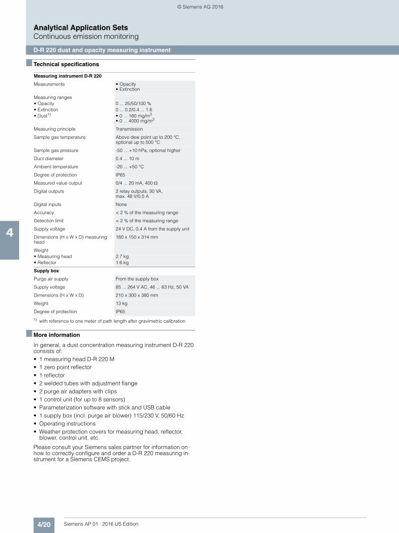
Measuring instrument D-R 220
Measurements • Opacity• Extinction
Measuring ranges• Opacity 0 ... 25/50/100 %• Extinction 0 ... 0.2/0.4 ... 1.6• Dust1) • 0 ... 160 mg/m3
• 0 ... 4000 mg/m3
Measuring principle Transmission
Sample gas temperature Above dew point up to 200 °C, optional up to 500 °C
Sample gas pressure -50 ... +10 hPa, optional higher
Duct diameter 0.4 ... 10 m
Ambient temperature -20 ... +50 °C
Degree of protection IP65
Measured value output 0/4 ... 20 mA, 400
Digital outputs 2 relay outputs, 30 VA, max. 48 V/0.5 A
Digital inputs None
Accuracy < 2 % of the measuring range
Detection limit < 2 % of the measuring range
Supply voltage 24 V DC, 0.4 A from the supply unit
Dimensions (H x W x D) measuring head
160 x 150 x 314 mm
Weight• Measuring head 2.7 kg• Reflector 1.6 kg
Supply box
Purge air supply From the supply box
Supply voltage 85 ... 264 V AC, 46 ... 63 Hz, 50 VA
Dimensions (H x W x D) 210 x 300 x 380 mm
Weight 13 kg
Degree of protection IP65
© Siemens AG 2016

4/21Siemens AP 01 · 2016 US Edition
Analytical Application SetsContinuous emission monitoring
New generation D-R 290 dust concentration measuring instrument
4
■ Overview
The D-R 290 is an optical opacity/dust monitor for plants with small to medium dust concentrations.
■ Benefits
• In-situ measuring procedure, continuous measurement• Super-wide band diodes (SWBD), which provides more stable
measuring results in comparison to devices with conventional LEDs
• Convenient operation, remote access option• Easy adjustment without additional equipment• Low-maintenance thanks to optimal purge air conduction• Data transmission via Modbus, in compliance with VDI 4201-3
■ Application
The D-R 290 monitors not only the efficiency of the filter plants by registering the residual dust content, but also reports instan-taneously when permissible levels of dust or flue gas emissions are exceeded. As a result it is often possible to intervene directly in the process of the plant to be monitored and thus ensure reli-able compliance with the specified limit values.
Areas of application• Furnace plants with semi-anthracite coal, brown coal, fuel oil
and combined heating• Converter plants, asphalt mixing plants• Cement manufacturing plants
Approvals• Suitability-tested by the TÜV Cologne, test report
936/21226948/A• Certified according to DIN EN 15267-3• Itemized in the list of suitable measuring devices for
continuous emission measuring• MCERTS
■ Design
System components D-R 290
Measuring head
The transmitter and receiver optics are integrated together with the electronics in a rugged and robust aluminum housing. The measuring head is mounted on the weld-in flange.
Reflector
The reflector is installed in a rugged and robust aluminum hous-ing. The reflector is mounted on the weld-in flange directly oppo-site the measuring head.
Purge air unit
A hose connects the measuring head and the reflector with the purge air unit. The filtered air is used to keep clean the scattered light interfaces of the measuring head and the reflector.
Optional:
Universal control and display unit D-ISC 100
The connected equipment is easy to configure and operate using the D-ISC 100 control and display unit. The display provi-des an immediate overview of the current measured values and the status of the measuring instruments.
Measured-value acquisition
In the simplest case the measured values and reference values are transferred to the plant's control system. The measured values and status signals that are output can also be fed to an emission calculator system for further processing, either via di-screte signals (4 to 20 mA and configurable relay contacts) or via Modbus according to VDI 4201-3.
Fail-safe shutters
The fail-safe shutters are mounted on the measuring head and the reflector side between the weld-in flanges and the con-nected devices (measuring head, reflector). In the event of a fault (failure of the power supply or purge air) they automatically close the path between the exhaust gas duct and the measuring equipment.
Electronics for fail-safe shutter
A control electronics system is required for each fail-safe shutter.
DURAG
ESC
D-ISC 100
Control and display unit
Purge air unit
Reflector Optical measuring unit
© Siemens AG 2016

4/22 Siemens AP 01 · 2016 US Edition
Analytical Application SetsContinuous emission monitoring
New generation D-R 290 dust concentration measuring instrument
4
Weather protection covers
Weather protection covers are available to protect the measur-ing head, the reflector, the purge air unit and the terminal boxes when the measuring system is installed outdoors.
Additional options:• Explosion proof design for EEx p, Zone 1 or Zone 2, 22• Temperature compensation• Filter set for sensitivity and linearity control
■ Function
The device operates using the double-pass method according to the auto-collimation principle. The light beam traverses the measuring distance twice. The attenuation of the light beam by the dust content in the measuring section is measured and eval-uated.
The universal control unit D-ISC 100 can be connected for the measured value display and parameter assignment, which al-lows up to eight dust and flow-rate measurement instruments.
The connected equipment is easy to configure and operate us-ing the D-ISC 100. The display provides an immediate overview of the current measured values and the status of the measuring instruments.
■ Technical specifications
1) with reference to one meter of path length after gravimetric calibration
■ More information
Please consult your Siemens sales partner for information on how to correctly configure and order a D-R 290 measuring in-strument for a Siemens CEMS project.
Measuring instrument D-R 290
Measurements • Opacity• Extinction
Measuring ranges• Opacity 0 ... 20 to 0 ... 100 %• Extinction 0 ... 0.1 to 0 ... 2.0• Dust1) 0 ... 80 mg/m3 to 0 ... 4 000 mg/m3
Measuring principle Transmission
Sample gas temperature Above dew point up to 250 °C, optional up to 1 000 °C, depending on application
Sample gas pressure -50 ... +20 hPa, optional higher
Duct diameter 1 ... 18 m
Ambient temperature -40 ... +60 °C
Degree of protection IP65, Ex optional
Measured value outputs 0/4 ... 20 mA, 400 Modbus RTU bi-directional
Digital outputs 2 relay outputs, permissible load DC 60 V, AC 30 V/0,5 A
Digital inputs None
Accuracy < 1 % of measuring range
Detection limit 0.75 % at extinction 0 ... 0.1
Reference point drift < 0.4 % of measuring range / month
Zero point drift < 0.4 % of measuring range / month
Auxiliary power 24 V DC/0,5 A
Dimensions (H x W x D) measuring head
363 x 185 x 398 mm
Weight 17 kg
Purge air supply
Purge air quantity Approx. 80 m3/h
Auxiliary power 115/230 V AC, 50/60 Hz, 0.37/0.43 kW
Dimensions (H x W x D) 350 x 550 x 500 mm
Weight 12 kg
Degree of protection IP55
© Siemens AG 2016

4/23Siemens AP 01 · 2016 US Edition
Analytical Application SetsContinuous emission monitoring
D-R 320 dust measuring instrument
4
■ Overview
The D-R 320 is an optical dust monitor for the smallest to medium dust concentrations in dry emissions and process gas.
■ Benefits
• Continuous measurement of dust concentration• Smallest certified measuring range 7.5 mg/m3
• Easy installation on standard flanges• Easy setup without manual adjustment• Automatic background light compensation, no light trap• Convenient operation, remote access option• Automatic control functions• Integrated purge air regulation and purge air control• Maintenance interval 6 months• Certified to EN 15267-3• Data transmission via Modbus, in compliance with VDI 4201-3
■ Application
The D-R 320 monitors not only the efficiency of the filter plants by registering the residual dust content, but also reports instan-taneously when permissible levels of dust or flue gas emissions are exceeded. As a result it is often possible to intervene directly in the process of the plant to be monitored and thus ensure reli-able compliance with the specified limit values.
Areas of application
Continuous emission monitoring, for example, on:• Incineration plants in general• Plants according to IED 2010/75/EU WID/17. BImschV• Plants according to IED 2010/75/EU LCPD/13. BImschV/
German TA-Luft• Waste, hazardous waste and sewage sludge incineration
plants• Cement manufacturing plants• Power plants with gas, oil, coal or co-firing• Plants for the incineration of biomass
Monitoring of:• Ventilation units• Filter units
Approvals• Suitability-tested by the TÜV Cologne, test report
936/21217455/A• Certified according to DIN EN 15267-3• MCERTS
■ Design
System components D-R 320
Transmitter / receiver unit D-R 320 M
The transmitter and receiver optics are integrated together with the electronics in a compact unit in a rugged housing. The trans-mission-reception unit consists of the measuring head, the swivel adapter, the process connection and the process aper-ture panel. The measuring unit is installed via a DIN 100 PN 6 or ANSI 4" 150 lbs flange on the waste gas duct. No adjustment is required.
Supply unit D-TB 200
The supply unit of the dust concentration measuring instrument D-R 320 is used to supply electricity and purge air and provides the connection for the transfer of the measured data. The regu-lated purge air is used to keep clean the optical interfaces of the transmission and reception optics of the D-R 320. The device automatically reports any failure of the purging air.
Optional:
Universal control unit D-ISC 100
The connected equipment can be operated and configured con-veniently using the D-ISC 100 control and display unit. The dis-play provides an immediate overview of the current measured values and the status of the measuring instruments.
Measured-value acquisition
In the simplest case the measured values and reference values are transferred to the plant's control system. The measured val-ues and status signals that are sent can also be fed to an emis-sion calculator system for further processing, either via discrete signals (4 to 20 mA and configurable relay contacts) or via Modbus according to VDI 4201-3.
Fail-safe shutter
The swivel adapter can be optionally replaced with an adapter with a fully integrated fail-safe shutter. By using this fail-safe shutter the path between the measuring device and the waste gas is closed mechanically, but not airtight in the event of a fault (failure of power supply or purge air); the measuring device is temporarily protected against overheating in such cases. The measuring head takes over the control of the fail-safe shutter.
Weather protection covers
A weather protection cover is available to protect the measuring system when it is installed outdoors.
Measuring headMounting flange
Universal control unit D-ISC 100
Supply unit with inte-grated purge air supply
© Siemens AG 2016

4/24 Siemens AP 01 · 2016 US Edition
Analytical Application SetsContinuous emission monitoring
D-R 320 dust measuring instrument
4
Explosion proof design
An explosion proof design with pressurized enclosure according to EEx p, Zone 1 or Zone 2 is available for use in hazardous ar-eas.
■ Function
The device operates according to the backscattering principle. The light of a laser diode illuminates the dust particles in the measuring volume of the flue gas duct. The light reflected by the particles is measured and evaluated.
The D-R 320 does not require a light trap. The background light in the stack is detected by means of a special optical system with an integrated dual detector and automatically compen-sated without manual adjustment.
The universal control unit D-ISC 100 can be connected for the measured value display, which allows up to eight dust and vol-ume flow measurement instruments.
The connected equipment can be operated and configured con-veniently using the D-ISC 100. The display provides an immedi-ate overview of the current measured values and the status of the measuring instruments.
Control functions
The D-R 320 automatically performs zero and span check as well as contamination check at regular intervals and on demand. The device features an automatic contamination correction. Need for maintenance is immediately indicated by the electron-ics.
■ Technical specifications
■ More information
Please consult your Siemens sales partner for information on how to correctly configure and order a D-R 320 measuring in-strument for a Siemens CEMS project.
Measuring head
Measured variable Dust concentration
Measuring ranges 0 ... 5 mg/m3 to 0 ... 200 mg/m3
Measuring principle Backscattering
Sample gas temperature 0 ... 600 °C
Sample gas pressure -50 ... +50 hPa, optional higher
Duct diameter > 0.7 m
Ambient temperature -40 ... +60 °C
Degree of protection IP65
Measured value outputs 0/4 ... 20 mA, 400 Modbus RTU bi-directional
Digital outputs 2 relay outputs, permissible load 60 V DC, 30 V AC/0.5 A
Digital inputs None
Auxiliary power 24 V DC/0.5 A
Dimensions (H x W x D) 200 x 190 x 260/410 mm
Weight 15 kg
Supply box
Purge air supply Integrated blower
Supply voltage 115/230 V AC, 50/60 Hz, 0.37/0.43 kW
Dimensions (H x W x D) 480 x 450 x 320 mm
Weight 12 kg
Degree of protection IP65
© Siemens AG 2016

4/25Siemens AP 01 · 2016 US Edition
Analytical Application SetsContinuous emission monitoring
D-R 800 dust measuring instrument
4
■ Overview
D-R 800 is an innovative laser measuring instrument for monito-ring small to medium dust emissions according to the new Euro-pean regulations.
■ Benefits
• In-situ measuring procedure with continuous measurement• High sensitivity• Easy installation on one side of the flue• Use also on thick-walled stone/insulated channels• Easy installation• Long service life, since there are no moving parts, not even
within the flue• Probe with corrosion-resistant, nano-treated coating• Parameter assignment and operation via keyboard and easily
readable display directly on the device or via bus interface• Automatic function test with contamination correction
■ Application
The D-R 800 not only monitors the efficiency of the filter systems by registering the residual dust content, but also reports instan-taneously when permissible levels of dust or flue gas emissions are exceeded. As a result, it is often possible to intervene di-rectly in the process of the plant to be monitored and thus ensure reliable compliance with the specified limits.
Areas of application• Power plants • Cement works, metallurgy and timber industry, chemical in-
dustry etc.• Waste incinerators • Monitoring of dust filter systems
Certifications• Qualification tested by the TÜV Cologne, test report
936/21205307/A• Itemized in the list of suitable measuring devices for con-
tinuous emission measuring• Certified according to DIN EN 15267-3• MCERTS
■ Design
System components D-R 800
Measuring probe
The measuring probe of nano-treated stainless steel 1.4571 can be delivered in two lengths of approx. 400 and 800 mm (from mounting flange). A difference is made here between installation on a horizontal or vertical flue and between the German and En-glish language. The measuring probe is firmly connected to the operating unit including display.
Supply unit with integrated purge air supply
The supply unit supplies the probe with the required signals and the supply voltage over a connecting cable 3 or 10 m in length as well as with purge air through an additional air hose.
Mounting flange 130/240/500 mm
The connection flange made of carbon steel or stainless steel 1.4571 should protrude approximately 30 mm into the channel.
Optional:
Temperature compensation through additional analog input
Using an additional analog input, the temperature of the exhaust gas can be passed to the operating unit, thus enabling calcula-tion of the dust concentration corrected by the gas temperature.
Special material alloy 59 2.4605
As an alternative to the nano-treated stainless steel 1.4571, the probe can be manufactured from alloy 59 2.4605 (comparable to Hastelloy 2.4819).
Weather protection covers
Weather protection covers are available to protect the measur-ing system and the purge air unit for outdoor installation.
RS 485 andanaloguecurrentoutput
Supply unit with integrated purge air supply
Evaluation unitMeasuring lance
© Siemens AG 2016

4/26 Siemens AP 01 · 2016 US Edition
Analytical Application SetsContinuous emission monitoring
D-R 800 dust measuring instrument
4
■ Function
The D-R 800 device operates according to the forward-scatter-ing principle. The concentrated and modulated light from a laser diode penetrates the measuring volume. The light scattered by the dust particles in the forward direction is measured and eval-uated.
■ Technical Specifications
1) After gravimetric calibration
■ More information
Please consult your Siemens sales partner for information on how to correctly configure and order a D-R 800 measuring in-strument for a Siemens CEMS project.
Measuring instrument D-R 800
Measured variable Dust concentration
Measuring ranges 0 ... 10 mg/m3 to 0 ... 200 mg/m3 1)
Measuring principle Forward scattering
Sample gas temperature Above dew point up to 350 °C
Sample gas pressure -50 ... +10 hPa
Channel diameter 0,4 ... 8 m
Probe length 400/800 mm
Ambient temperature -20 ... +50 °C
Degree of protection IP65
Measured value outputs 2 x 0/4 ... 20 mA, 500 Modbus RTU (RS 485)
Digital outputs 4 programmable relay outputs, permissible load 24 V/25 VA
Digital inputs 2 isolated inputs, programmable
Accuracy < 1 % of the measuring range
Detection limit < 0,5 % of the measuring range
Reference point drift < 0,7 % of measuring range/month
Zero point drift < 0,15 % of measuring range/month
Auxiliary power 85 ... 264 V AC, 47 ... 63 Hz, 50 VA
Dimensions (H x W x D)
• Measuring probe 160 x 160 x 600/1 000 mm
• Supply box 380 x 300 x 210 mm
Weight
• Measuring probe 7 kg
• Supply box 13 kg
Purge air supply Integrated in terminal box
© Siemens AG 2016

4/27Siemens AP 01 · 2016 US Edition
Analytical Application SetsContinuous emission monitoring
D-RX 250 combination probe
4
■ Overview
The combined probe sensor D-RX 250 is a single rod measure-ment probe for simultaneous measurement of dust concentra-tion, volume flow, temperature and absolute pressure.
■ Benefits
• Only one probe/installation opening in the exhaust gas channel
• Compact design, no moving parts, no consumable parts• Continuous conversion to normalized dust concentration in
mg/Nm3 and to normalized volume flow in Nm3/h• LCD display in mg/Nm3, Nm3/h, °C and hPa, one analog
output for each measurement value• Parameterization at the control unit without the need of a PC or
other tools
■ Application
By combining four selected measuring functions in a single de-vice it is possible to automatically calculate the pollutant mass flow for the preparation of the emission declaration in addition to monitoring the pollutant dust.
Areas of application• Not suitable for use behind electrostatic precipitators
Approvals• Suitability-tested by the TÜV Cologne,
test report 936/800006/A• Itemized in the list of suitable measuring devices for
continuous emission measuring• MCERTS incl. testing according to DIN EN 15267-3
■ Design
System components D-RX 250
Probe
The probe consists of the probe measuring rod and the mea-sured value processing by the electronics in the measuring head. The probe measuring rod is a probe section that protrudes into the dust duct and is fastened with a flange in the duct. The probe measuring rod is insulated in design because of the tri-boelectric measurement and has two chambers for differential pressure measurement. The two chambers for pressure mea-surement are connected to a differential pressure transmitter. One of the two chambers is also connected to the absolute pres-sure transducer in the transmitter. The gas temperature is mea-sured via a measurement resistance in a third chamber in the center of the probe section. The electronic measured value pro-cessing is performed in the probe housing. The temperature of the measurement resistance and the triboelectric raw value are determined here. The two raw values of temperature and tribo signal are transferred digitally to the transmitter.
Differential pressure transducer
The differential pressure transducer converts the differential pressure, created by the gas flowing in the probe measuring rod, into a gas velocity variable.
Transmitter
The transmitter provides the supply voltages for the probe and the measuring transducer for absolute pressure and differential pressure, reads in the raw measured values of these modules and transfer the measured values via the RS 485 interface to the evaluation unit. Through the RS 485 interface the transmitter reads the probe values of the triboelectric measured signal and the temperature.
The differential pressure transducer is connected to the transmit-ter by means of a two-wire cable. The absolute pressure trans-ducer is located inside the transmitter housing. It receives the pressure from the chamber via a special rod.
Control and evaluation unit
Differential pressure unit
TransmitterProbe
Max. 1 000 m
© Siemens AG 2016

4/28 Siemens AP 01 · 2016 US Edition
Analytical Application SetsContinuous emission monitoring
D-RX 250 combination probe
4
Control and evaluation unit
The control and evaluation unit reads out the raw measured val-ues from the transmitter. The measured values for normalized dust concentration and normalized volume flow are calculated in the unit.
It is possible to output all analog values via Modbus or 4/20 mA signals and all status signals via isolated contacts.
Measured-value acquisition
In the simplest case a recorder is used to record the measured values and the reference values. The measured values and sta-tus signals that are output can also be fed into an emission cal-culator system for further processing.
Optional:• Weather protection cover• Change-over cock for back purging/zero point control• Automatic cyclical probe back purging for high dust concen-
trations• Hastelloy probes for corrosive gases• Purge air connection at flange
■ Function
Dust concentration
The dust concentration is calculated according to the triboelec-tric measuring principle. The tribo probe measures the electrical charge of the incident particles.
Volume flow
The measurement of the volume flow is based on the mechanical action principle. The probe has two separate chambers, be-tween which a differential pressure builds up under flow.
Absolute pressure
The absolute pressure in the flue gas is measured by a pressure transmitter in one chamber of the probe.
Temperature
The temperature is measured directly in the center of the flue gas in a separate chamber within the probe with a temperature sensor.
■ Technical specifications
1) Flue gas velocity > 5 m/s concentration after gravimetric calibration
■ More information
Please consult your Siemens sales partner for information on how to correctly configure and order a D-RX 250 combined probe sensor for a Siemens CEMS project.
D-RX 250 combined probe sensor
Measurements • Dust concentration• Volume flow• Pressure• Temperature
Measuring ranges • 0 ... 10 to 0 ... 500 mg/Nm3
• 0 ... 9 999 999 Nm3/h1)
• 800 ... 1300 hPa• 0 ... 200 °C, optional 0 ... 350 °C
Measuring principle• Dust Tribo electric• Volume Differential pressure
Sample gas temperature Above dew point up to 200 °C, optional up to 350 °C
Sample gas humidity < 80 %
Sample gas pressure -200 ... +200 hPa
Duct diameter 0.3 ... 5 m
Ambient temperature -20 ... +50 °C
Degree of protection IP65
Measured value outputs 4 x 0/4 ... 20 mA, 500 Modbus RTU (RS 485)
Digital outputs 7 relay outputs, permissible load 48 V/0.5 A
Digital inputs 6 isolated inputs
Accuracy < 2 % of the measuring range
Detection limit < 2 % of the measuring range
Reference point drift < 1 % of measuring range / month
Zero point drift < 1 % of measuring range / month
Auxiliary power 115/230 V AC, 50/60 Hz, 50 VA
Dimensions• Probes 180 x 180 x (340 + probe length) mm• Probe length 250/400/700/1000 mm
Weight• Probe 9.5 kg• Electronics 22 kg
Options
Probe back purging, purge air supply 3 bar
Isolator purging, continuous purge air supply
Approx. 2 m3/h
© Siemens AG 2016

4/29Siemens AP 01 · 2016 US Edition
Analytical Application SetsContinuous emission monitoring
D-FL 100 volume flow measuring system
4
■ Overview
The D-FL 100 volume flow measuring system measures the flow rate in dry emissions with a probe using the differential pressure principle.
■ Benefits
• Reliable measurement of flue gas velocity, even at high tem-peratures
• Versions with or without counter-support and for point measurement
• Calculation of volume flow at standard conditions with evalu-ation unit D-FL 100-20
• Maintenance interval 6 months• Automatic backpurging device (optional)
■ Application
As in-situ measuring system, the measuring equipment deter-mines the measured values without sampling directly in the duct through which gas is flowing.
Areas of application• Volume flow measurement at high temperatures• Plants with small or large flue cross-sections• Volume flow measurement at high pressure
Approvals• Suitability-tested by the TÜV Cologne,
test report 936/800006/A• Itemized in the list of suitable measuring devices for
continuous emission measuring• Certified according to DIN EN 15267-3• MCERTS
■ Design
System components D-FL 100
Dynamic pressure probe
Each dynamic pressure probe of type D-FL 100 is a customized product for the respective measuring location. Three different sizes are available depending on the length of the planned mea-surement path:
• System 1: 22 x 24 mm2 for 0.4 to 2 m length, with one-sided (max. 1 m) or two-sided mounting
• System 2: 50 x 53 mm2 for 0.4 to 4 m length, with one-sided (max. 1.5 m) or two-sided mounting
• System 3: 90 x 100 mm2 for 0.4 to 8 m length, two-sided mounting
Evaluation unit
Temperature transducer (optional)
Flow direction
Cross over cock
Flow probe
Absolute pressure transducer (optional)
Flow 4 ... 20 mA
Differential pressure transducer
4 ... 20 mA4 ... 20 mA
© Siemens AG 2016

4/30 Siemens AP 01 · 2016 US Edition
Analytical Application SetsContinuous emission monitoring
D-FL 100 volume flow measuring system
4
Adapter
The cross-over cock is either connected by an adapter to the dif-ferential pressure transducer directly on the probe (not for sys-tem 3) or via a hose or tube connection.
Cross-over cock
Cross-over device for the backpurging of the dynamic pressure probe
Differential pressure transducer
The transducer is delivered with factory set defaults for the or-der-specific configuration. The zero point should be calibrated after the installation.
Counter-support
A counter-support is required for a probe mounted on two sides. The counter-support supports the probe not only mechanically, but also enables the compensation of the temperature-depen-dent longitudinal expansion of the probe.
Mounting tubes with flange
Mounting tubes made of stainless steel 1.4571, adapted to the plant conditions, are available in various lengths. A single flange is required for a one-sided probe; otherwise two flanges are al-ways required.
Optional:
Evaluation unit
The evaluation unit D-FL 100-20 evaluates the measured signal from the differential pressure transducer. A 4 to 20 mA current signal is available as measured value output. A Modbus inter-face according to VDI 4201 for the connection of an emission evaluation calculator with digital interface is available in addition to the 4 to 40 mA current signal output. The front panel contains five LEDs and one USB port. The LEDs signal the system's cur-rent status/operating state.
The various parameters, such as standard density, substitute values for pressure and temperature in the exhaust gas duct, k-factor and measuring ranges are input via the USB port with the help of a PC or the associated software D-ESI 100.
Software D-ESI 100
Software for assigning parameters, visualizing the measured data, and carrying out AST, QAL2 and QAL3 for D-FL 100-20.
The D-ESI 100 can be parameterized, maintained and (when faults occur) analyzed via the USB port with the help of a PC and the associated software.
Universal control unit D-ISC 100 with evaluation unit D-FL 100-20
The connected equipment can be operated and configured con-veniently using the D-ISC 100. The display provides an immedi-ate overview of the current measured values and the status of the measuring instruments.
Automatic back purging unit
An automatic back purging device to keep the measuring open-ings clean is available for applications with high dust loads.
Weather protection covers
A weather protection cover is available to protect the probe head and the back purging control when the measuring system is in-stalled outdoors.
Additional options:• Absolute pressure transducer• Temperature transducer• Special designs in other materials for applications with partic-
ularly aggressive exhaust gases or higher gas temperatures: Standard material for probe stainless steel 1.4571, depending on measurement task also Hastelloy, Inconel or other materials
• dP transducer in Ex-version
■ Function
The D-FL 100 measuring system operates according to the me-chanical action principle. The probe has two separate cham-bers, between which the flow builds up a differential pressure. Taking account of the other flow parameters such as absolute pressure and temperature, for example, the volume flow can be converted from operating to standard conditions with the help of the D-FL 100-20 evaluation unit.
■ Technical specifications
1) Optional pressure and temperature correction
■ More information
Please consult your Siemens sales partner for information on how to correctly configure and order a D-FL 100 measuring sys-tem for a Siemens CEMS project.
Measuring system D-FL 100
Measurements • Flue gas velocity• Volume flow1)
Measuring ranges • 2 ... 50 m/s• 0 ... 3 000 000 m3/h
Measuring principle Differential pressure
Sample gas temperature Above dew point up to 450 °C, optional up to 850 °C
Sample gas pressure -200 ... +200 hPa, optional higher
Duct diameter 0.4 ... 8 m
Ambient temperature -20 ... +50 °C
Degree of protection IP65
Measured value output 0/4 ... 20 mA, 500
Digital outputs 2 relay outputs, permissible load 48 V/0.5 A
Digital inputs None
Accuracy < 2 % of the measuring range
Detection limit < 3 m/s
Reference point drift < 0.5 % of measuring range / month
Zero point drift < 0.5 % of measuring range / month
Auxiliary power 18 ... 32 V DC/1 A, 90 ... 264 V AC, 48 ... 62 Hz, 100 VA
Dimensions• Probes 380 x 160 x (300 + probe length) mm• Probe length 0.4 ... 2/0.4 ... 4/0.4 ... 8 m
Weight 32 kg + 6.8 kg/m probe length
Purge-air supply (optional) 6 ... 8 bar for back purging
© Siemens AG 2016

4/31Siemens AP 01 · 2016 US Edition
Analytical Application SetsContinuous emission monitoring
D-FL 220 volume flow measuring system
4
■ Overview
The D-FL 220 is a volume flow measuring system for ultra-sonic measuring of flow and volume flow, especially for wet and ag-gressive smoke emissions.
■ Benefits
• In-situ measuring method• Measurement possible below dew point and for high dust
concentrations• Continuous measurement of normal volume flow and gas velocity• Automatic zero point and reference point control• Remote access possible, digital interface according to
VDI 4201-3• Operation with or without control unit• Very low maintenance, maintenance interval 6 months
■ Application
As in-situ measuring system, the measuring equipment deter-mines the measured values without sampling directly in the duct through which gas is flowing.
Areas of application• Volume flow measuring at low speeds• Plants with damp and/or aggressive exhaust gas, for example,
in waste incineration plants• Volume flow measurement at high dust content
Approvals• Suitability-tested by the TÜV Cologne, test report
936/21218490/A • Certified according to DIN EN 15267-3• Itemized in the list of suitable measuring devices for
continuous emission measuring
■ Design
System components D-FL 220
Measuring heads
Two identically designed measuring heads, set for type A and type B, are used. Depending on the application data, different depth-of-penetration lengths are required, for example, from 100 to 1100 mm.
Stainless steel 1.4571 is used as probe material. The housing is made of impact-proof polyamide.
A 4 mA to 20 mA current signal is available as measured value output which measures the velocity and/or the volume flow and can be connected, for example, to a emission evaluation calcu-lator or a recorder. Two relay contacts are available for signaling. Also available is a Modbus interface according to VDI 4201-3 for the connection of an emission evaluation calculator with digital interface. The various parameters are entered during the instal-lation on site. The USB port is on the rear.
Purge flanges
The purge air which cools the ultra-sonic transducer and keeps it clean is supplied via purge flange (one for each measuring head). A toggle-type fastener connects the purge flange to the measuring head.
Mounting tubes with flange
Mounting tubes made of stainless steel 1.4571 or of glass-fiber reinforced plastic, adapted to the plant conditions, are available.
Purge air unit
A hose connects the two measuring heads to the purge air unit. The filtered air is used to cool the measuring heads and to keep the transducers clean.
Terminal box
Terminal box to output the data with connecting cable for the two sensors and customer terminal strip.
Software D-ESI 100
Software to assign parameters, to visualize the measured data, and to carry out AST, QAL2 and QAL3.
The D-ESI 100 can be parameterized, maintained and (when faults occur) analyzed via the USB port with the help of a PC and the associated software.
Optional:
Universal control unit D-ISC 100
The connected equipment can be operated and configured con-veniently using the D-ISC 100. The display provides an immedi-ate overview of the current measured values and the status of the measuring instruments.
Weather protection covers
Weather protection covers are available to protect the measur-ing heads when the measuring system is installed outdoors.
Additional options:• Absolute pressure transducer• Temperature transducer
Duct Measuring head
Purge air
Purge air
© Siemens AG 2016

4/32 Siemens AP 01 · 2016 US Edition
Analytical Application SetsContinuous emission monitoring
D-FL 220 volume flow measuring system
4
■ Function
The D-FL 220 measuring system operates according to the acoustic transit time differential method.
Two identical sensors transmit and receive ultra-sonic pulses re-ciprocally. The system calculates precisely the gas velocity and the gas temperature from the transit time difference dependent on the direction. The volume flow is calculated taking into con-sideration the cross-section, the sample gas temperature and the absolute pressure. The D-FL 220 performs internal self-mon-itoring routines and is very low maintenance.
■ Technical specifications
1) Optional pressure and temperature correction
■ More information
Please consult your Siemens sales partner for information on how to correctly configure and order a D-FL 220 measuring sys-tem for a Siemens CEMS project.
Measuring system D-FL 220
Measurements • Flue gas velocity• Volume flow1)
• Temperature
Measuring ranges • 0 ... 40 m/s• 0 ... 3 000 000 m3/h• 0 ... 400 °C
Measuring principle Ultrasonic transit-time differential
Sample gas temperature 0 ... 300 °C, optional higher
Sample gas pressure -50 ... +20 hPa, optional higher
Duct diameter 0.5 ... 13 m, temperature-dependent
Ambient temperature -20 ... +50 °C, measuring head: -40 ... +70 °C
Degree of protection IP65
Measured value output 0/4 ... 20 mA, 400 Modbus RTU bi-directional
Digital outputs 2 relay outputs, permissible load 48 V/0.5 A
Digital inputs None
Accuracy < 2 %
Detection limit < 0.3 % of measuring range
Reference point drift < 0.3 % of measuring range / month
Zero point drift < 0.2 % of measuring range / month
Auxiliary power 24 V DC/0.5 A
Dimensions standard measuring head Ø 190 x 570 mm
Weight 17 kg
Purge air supply
Purge air quantity Approx. 80 m3/h
Auxiliary power 115/230 V, 50/60 Hz, 0.37/0.43 kW
Dimensions (H x W x D) 350 x 550 x 500 mm
Weight 12 kg
Degree of protection IP55
© Siemens AG 2016

4/33Siemens AP 01 · 2016 US Edition
Analytical Application SetsContinuous emission monitoring
D-ISC 100 display and control unit for dust and volume flow measuring instruments
4
■ Overview
The D-ISC 100 universal control unit permits the connection of up to 8 sensors combining dust and volume flow measurements on one display.
■ Benefits
• Connection of up to 8 sensors• Large liquid crystal display (LCD) for display of the measured
values• Automatic detection of connected sensors• Easy parameter assignment of connected sensors• Operation locally via membrane keyboard or USB port, or
remote control via the RS 485 interface• Modular design, four slots available for extension modules• Slot for external converter• No maintenance costs• Easy to update via SD card
■ Application
The control unit can supply a single sensor or a system consist-ing of two sensors with power. Several sensors that are con-nected via a network can also be connected to the D-ISC 100. In this case each of the sensors must be supplied with power by means of a separate terminal box, supply unit or evaluation unit. Modbus links the sensors to each other and to the D-ISC 100.
The display provides an immediate overview of the status of the connected devices. The current measured values can be dis-played without the necessity of direct access to the sensors. It is also possible to visualize the measured values with bar chart display.
The connected sensors can be queried, controlled and param-eterized with the control unit. Operation takes place directly via the membrane keyboard of the control unit. Alternatively, you can connect a PC via the integrated USB port. In conjunction with the Web server technology software D-ESI 100, remote sup-port is possible via the Internet.
The control unit features four slots for extension modules, for ex-ample, Modbus RTU or analog / digital input and output mod-ules.
You also have the option of including an external converter (e.g. PROFIBUS DP) inside the unit. This eliminates the need for an additional housing in equivalent degree of protection.
Approvals
Type-tested according to European directive EN 15267 for con-tinuous emission measurements in connection with the test re-ports no. 936/21217455, 936/21218492 and 936/21218490 of the Technical Inspectorate of the Rhineland region (TÜV Rhein-land)
■ Design
The following functions can be added to the D-ISC 100 control unit by means of plug-in modules:• Modbus RTU module• Analog input module with four analog inputs: 0 to 20 mA with
2/4 mA live zero, burden 50 • Analog output module with four analog outputs: 0 to 20 mA
with 4 mA live zero, max. burden 400 • Digital input module with eight digital inputs• Digital output module with eight digital outputs
© Siemens AG 2016

4/34 Siemens AP 01 · 2016 US Edition
Analytical Application SetsContinuous emission monitoring
D-ISC 100 display and control unit for dust and volume flow measuring instruments
4
■ Technical specifications
■ More information
Please consult your Siemens sales partner for information on how to correctly configure and order a D-ISC 100 control unit for a Siemens CEMS project.
Basic unit
Output signal 0 ... 20 mA, zero point 4 mA
Maximum burden 400
Relay outputs 3 x status, isolated (limit value, fault, control cycle, etc.)
Maximum switching power 48 V/0.5 A
Inputs 1 x function, isolated
Ambient temperature -20 ... +50 °C, optional -40 ... +60 °C
Electrical data
Line voltage 90 ... 264 V, 48 ... 62 Hz
Power Approx. 100 W
Auxiliary power for sensors 24 V DC/2 A
Mechanical specifications
Material Stainless steel 1.4301
Color RAL 5017
Degree of protection IP65
Weight 5 kg
Dimensions (H x W x D) 130 x 330 x 220 mm
Expansion options
Modbus RTU module
Interface RS 485, serial
Baud rate 9600 ... 57 600 Bd
Analog input module
Output signal 0 ... 20 mA, zero point 0/2/4 mA adjustable
Load 50
Analog output module
Output signal 0 ... 20 mA, zero point 4 mA
Maximum burden 400
Digital input module
Inputs 8 x function, isolated
Digital output module
Relay outputs 8 x status, isolated (limit value, fault, control cycle, etc.)
Converter module
Type PROFIBUS DP
© Siemens AG 2016

4/35Siemens AP 01 · 2016 US Edition
Analytical Application SetsContinuous emission monitoring
D-EMS 2000 Environmental and process data management system
4
■ Overview
The D-EMS 2000 environmental and process data management system is a modular system for the continuous acquisition, long-term storage, calculation and visualization of environmental and process data.
■ Benefits
• Instrument for monitoring legally prescribed limit values and recording their observance
• Emission monitoring and remote data transmission to the authorities
• Corresponds to EU directives 2000/76/EC, 2001/80/EC and 2010/75/EC
• Adjustable to any plant size through to complete assessment of complex industrial sites
• Continuous monitoring of 1 to 320 components per system workstation
• Interconnection of any number of components via data networks
• Visualization available in 19 languages
■ Application
The D-EMS 2000 standard system is designed for small to me-dium sized industrial sites whose emission data, immission data or process data must be recorded in line with government regu-lations for measured data logging.
Approvals• Suitability-tested by TÜV in accordance with German TA-Luft,
1., 2., 13., 17., 27., 30. and 31. BImSchV• Itemized in the list of suitable systems for evaluation of
continuous emission measuring• Certified according to DIN EN 15267-2• MCERTS certified
■ Design
Measured data acquisition:• Analog/digital inputs as
- 19" rack with ring memory- Local DIN rail modules
• Data communication via bus systems, Modbus RTU/ TCP, PROFIBUS, Elan, OPC UA
Backup on HD/SSD
SystemRaid 1
Authority
Ring memory6 years int, day + protocols 30 days 1 min + 1 s
Ring memory > 32 days
Ring memory > 32 days
Ring memory> 5 yearsIndividual valuesProtocols
System Workstation D-EMS 2000
Internet
TCP/IPTCP/IP
1 ...
8
DCF77GPS
D-EMS 2000 Client
D-EMS 2000 Client
D-EMS 2000 Client
D-MS 500 KE
4-20 mA, Modbus,
PROFIBUS, OPC, ELAN
4-20 mA, Modbus,
PROFIBUS, OPC, ELAN
D-EMS 2000 CS
4-20 mA, Modbus,
PROFIBUS, OPC, ELAN
© Siemens AG 2016

4/36 Siemens AP 01 · 2016 US Edition
Analytical Application SetsContinuous emission monitoring
D-EMS 2000 Environmental and process data management system
4
■ Function
Data sources• Emission data• Immission data• Meteorological data• Water data• Process data
Data export• Data interface to MS-Excel with option of further measured
data evaluation, e.g. for fulfillment of environmental protection officer’s reporting duties
• Measured data can be transferred to authorities via standard remote communication or via Internet
• Merging of measured data e.g. for greenhouse emission trading
• Remote service interface for fast and cost effective service
Data security• Industrial type evaluation PC with vibration-proof hard disks in
RAID 1 array and special air cooling with filter system• Paperless data storage to replace recorders and printers is
possible through integrated data security, which is guaranteed on several levels in the system
• Intermediate storage of the raw input values at minute intervals in data communication unit D-MS 500 KE
• Storage of raw input values in one-second intervals• Data backup on external redundant drive
Internet/intranet connection• Data transmission to an Internet server with HTML standard
masks via standard software (MS Internet Explorer)• Password protected control of daily emission values including
the classification records
Visualization• Measured data logging according to official regulations• Classification tables, daily, monthly and annual records• Representation of current, prognostic and historic measured
data in bar/linear form• Pollutant compensation, characteristics curve and correlation• Automatic alarm and information system
Annual emission declaration• Automatic preparation of annual emission declaration, from
the individual values stored in the system, according to 11. BlmSchV
• Compatible with official software, import/export module• Automatic filling in of forms• Reading in of historical emission declarations
■ More information
Please consult your Siemens sales partner for information on how to correctly configure and order a D-EMS 2000 environmen-tal and process data management system for a Siemens CEMS project.
© Siemens AG 2016

4/37Siemens AP 01 · 2016 US Edition
Analytical Application SetsContinuous emission monitoring
D-EMS 2000 CS Environmental and process data management system
4
■ Overview
The D-EMS 2000 CS environmental and process data management system is an affordable compact system for small to medium plants.
■ Benefits
• Independently operating module for the acquisition, long-term storage, calculation and visualization of environmental and process data
• Instrument for monitoring legally prescribed limit values with automatic recording
• Continuous monitoring of 1 to 12 components, connected via bus communication or hard-wired
• Compact system, no additional evaluation PC required• Windows-based and certified D-EMS 2000 software• All modules of the D-EMS 2000 system can be used• Visualization available in 19 languages
■ Application
The D-EMS 2000 CS compact system is designed for small to medium sized industrial plants whose emission data, immission data or process data must be recorded in line with public author-ity regulations for measured data logging.
Approvals• Suitability-tested by TÜV in accordance with German TA-Luft,
1., 2., 13., 17., 27., 30. and 31. BImSchV• Itemized in the list of suitable systems for evaluation of
continuous emission measuring• Certified according to DIN EN 15267-2• MCERTS certified
■ Design
Three available device types:• Compact system in 19", 3HU rack• Desktop version with monitor / keyboard / mouse• 19", 1HU slide-in unit with extendable keyboard and hinged
monitor
■ Technical specifications
■ More information
Please consult your Siemens sales partner for information on how to correctly configure and order a D-EMS 2000 CS compact system for a Siemens CEMS project.
Backup on HD/SSD
Authority Ring memory6 years int, day+ protocols 30 days 1 min + 1 s
Internet
TCP/IP
DCF77GPS
D-EMS 2000 Client
D-EMS 2000 Client
D-EMS 2000 Client
4-20 mA, Modbus, PROFIBUS, OPC, ELAN
Device versions • Compact system in 19", 3HU rack
• Desktop version with monitor/keyboard/mouse
• 19" slide-in assembly
PC Intel based dual-core PC with Windows 7 Pro & 8, 2 GB RAM and 120 GB SDD
Inputs / outputs Max. 3 cards:• Combination card
4 AI, 8 DI, 2 AO, 4 DO• Input card 8 AI, 15 DI• Output card 8 AO• Output card 16 DO
Connection of bus systems • Modbus RTU/ TCP, PROFIBUS, Elan, OPC UA
• Analog/digital inputs: 12/24• Analog/digital outputs: 12/24
Interfaces • 1 x VGA • 2 x USB• 1 x RJ 45• 3 x serial (RS 232 or RS 485)• BNC for DCF77 - radio clock
Ambient temperature 5 ... 40 °C
Degree of protection IP20
Operating voltage 115/230 V AC, 50/60 Hz, 100 VA
© Siemens AG 2016