contents - · pdf filecold dark / ready to go ... anti-torque pedals ... bell named it uh-1...
TRANSCRIPT


Aerosoft HUEY X 1.00 manual
Page 1 of 33
CONTENTS
COPYRIGHTS .................................................................................................................................................................. 3 CREDITS.......................................................................................................................................................................... 4 SYSTEM REQUIREMENTS ............................................................................................................................................... 4 CONTACT SUPPORT ....................................................................................................................................................... 4 INSTALLATION AND REMOVAL ...................................................................................................................................... 5 IN FSX ............................................................................................................................................................................. 5
MODELS AND LIVERIES .............................................................................................................................................. 5 COLD DARK / READY TO GO ....................................................................................................................................... 5 LIMITATIONS .............................................................................................................................................................. 5
FLIGHT MODEL ....................................................................................................................................................... 5 TURBINE ................................................................................................................................................................. 6 ROTOR BRAKE ........................................................................................................................................................ 6
FSX SETTINGS ............................................................................................................................................................. 6 CONTROL HARDWARE ............................................................................................................................................... 6 AEROSOFT SOUND MODULE ..................................................................................................................................... 6
FLYING THE HUEY .......................................................................................................................................................... 7 SYSTEMS ........................................................................................................................................................................ 8
CAUTION SYSTEM ...................................................................................................................................................... 8 ICE AND RAIN REPELLENT .......................................................................................................................................... 8 DOORS AND WINDOWS ............................................................................................................................................. 8 LIGHTING ................................................................................................................................................................... 9 OIL SYSTEMS .............................................................................................................................................................. 9 ELECTRICAL SYSTEM .................................................................................................................................................. 9 ENGINE VIBRATION INDICATOR ............................................................................................................................... 10 FUEL SYSTEM ........................................................................................................................................................... 10 HYDRAULIC SYSTEM ................................................................................................................................................. 10 ENGINE AND POWER TRAIN SYSTEMS ..................................................................................................................... 11 PILOT CONTROLS ..................................................................................................................................................... 11
ANTI-TORQUE PEDALS ......................................................................................................................................... 11 COLLECTIVE PITCH LEVER .................................................................................................................................... 11 CYCLIC STICK ........................................................................................................................................................ 11
GYRO ........................................................................................................................................................................ 12 AVIONICS ................................................................................................................................................................. 12
TRANSPONDER .................................................................................................................................................... 12 COMMUNICATION AND NAVIGATION RADIOS ....................................................................................................... 12
PANELS AND GAUGES .................................................................................................................................................. 13 LEFT MAIN PANEL .................................................................................................................................................... 14 RIGHT MAIN PANEL ................................................................................................................................................. 15 CENTER CONSOLE AFT ............................................................................................................................................. 16 CENTER CONSOLE FRONT ........................................................................................................................................ 17 ENGINE INSTRUMENTS ............................................................................................................................................ 18 OVERHEAD PANEL ................................................................................................................................................... 19 CIRCUIT BREAKER PANEL ......................................................................................................................................... 20 MISCELLANEOUS ...................................................................................................................................................... 21
OPERATING LIMITATIONS ............................................................................................................................................ 22 TYPE OF OPERATION ................................................................................................................................................ 22 AMBIENT AIR TEMPERATURE LIMITATIONS ............................................................................................................ 22 ALTITUDE LIMITATIONS ........................................................................................................................................... 22 MAXIMUM GROSS WEIGHT ..................................................................................................................................... 22
Aerosoft HUEY X 1.00 manual
Page 2 of 33
CHECKLISTS .................................................................................................................................................................. 23 INTERIOR CHECK ...................................................................................................................................................... 23 ENGINE PRE-START .................................................................................................................................................. 24 STARTING ................................................................................................................................................................. 24 ENGINE RUN-UP....................................................................................................................................................... 24 BEFORE TAKE-OFF .................................................................................................................................................... 25 ADDITIONAL FOR IFR FLIGHTS, CHECK IN HOVER TAXI ............................................................................................ 25 BEFORE DEPARTURE ................................................................................................................................................ 25 AFTER TAKEOFF / CRUISE......................................................................................................................................... 26 DESCENT / BEFORE LANDING .................................................................................................................................. 26 AFTER LANDING ....................................................................................................................................................... 26 SHUTDOWN ............................................................................................................................................................. 26
APPENDIX A: THE AEROSOFT INSTALLER AND LAUNCHER .......................................................................................... 27
Aerosoft HUEY X 1.00 manual
Page 3 of 33
THE BELL UH-1H (UH-1D) / BELL 205A-1
The Bell UH 1(Bell 205) is without a doubt one of the most famous helicopters. The first versions where produced
in 1956 and it is still manufactured today. Bell named it UH-1 Iroquois but it became better known under the Huey
nickname. Without a doubt the Vietnam War played an important role in the development and fame of the
aircraft. For the first time infantry were highly mobile and could operate anywhere in the range of the Huey.
Casualties could be med evacuated fast. It changed the face of war from fixed fronts to a series of skirmishes and a
far better chance of survival when you got wounded (assuming you were on the side that had helicopters).
The UH-1H was a development on the UH-1D model, with the main difference of a stronger engine. The 1,400 shp
Lycoming T-53-L-13 however was soon shown to be a bit too powerful for the gear box and it is almost always
limited to a lower output (often 1,100 shp).
The civilian version was called the Bell 205 and although not as successful as the military version they were
produced in the thousands and are certified for nearly any role a helicopter can perform.
Please note that the German Bundeswehr Hueys are built in Germany by Dornier and use the UH-1D designation
although they are in fact identical to the UH-1H as flown by the US armed forces. Pleas note that we use the UH-
1D designation.
COPYRIGHTS
The manual, documentation, video images, software and all the related materials are copyrighted and cannot be
copied, photocopied, translated or reproduced to any electronic medium or machine legible form, neither
completely nor in part, without the previous written consent of AEROSOFT. THE SOFTWARE IS FURNISHED «AS IS»
AND IT DOES NOT COME FURNISHED WITH ANY GUARANTEE IMPLICIT OR EXPRESS. THE AUTHOR DECLINES EVERY
RESPONSIBILITY FOR CONTINGENT MALFUNCTIONS, DECELERATION, AND ANY DRAWBACK THAT SHOULD ARISE,
USING THIS SOFTWARE.
Copyright © 2011 AEROSOFT and Joachim Schweigler (SPECIFIC - 3D - DESIGN). All rights reserved. Microsoft
Windows, and Flight Simulator are registered trademarks or trademarks of Microsoft Corporation in the United
States and/or other Countries. All trademarks and brand names are trademarks or registered trademarks of the
respective owners. Copyrights are serious stuff. If you find any pirated copies of this software please notify us at
[email protected]. We will make sure reports of copyrights violation are rewarded.
Aerosoft GmbH
Lindberghring 12
D-33142 Büren
Germany
www.aerosoft.com
Aerosoft HUEY X 1.00 manual
Page 4 of 33
CREDITS
Concept: Joachim Schweigler (SPECIFIC - 3D - DESIGN) & Aerosoft
Modeling/Texturing/Animation: Joachim Schweigler (SPECIFIC - 3D - DESIGN)
Project Management: Mathijs Kok (Aerosoft)
Manual, documentation: Mathijs Kok (Aerosoft) & many others
Manual corrections: Christoph Beck
XML coding: Finn Jacobsen (Aerosoft)
Flight modeling: John Cagle & Aerosoft
Sounds: Andriano Martoni & William Lennox (Aerosoft)
Installer: Andreas Mügge
Testing: Several good folks who will all be getting a copy
Special thanks to Mr. Mallwitz and Mr. Schröder at Bückeburg airfield and Mr. Sarmann and Mr. Buckschad at
Celle Faßberg airfield for the assistance. In general, the German Bundeswehr has been most helpful.
SYSTEM REQUIREMENTS
Intel Core 2 Duo E6850 CPU (Core 2 Quad advised)
2 GB RAM
Direct X 9 compatible Graphics Card with minimal 512 MB
Microsoft FSX (with SP2 or Acceleration)
Windows XP, Windows VISTA, Windows 7 (fully updated)
Adobe Acrobat® Reader 8 minimal to read and print the manual (1)
This product is compatible with DX10 as much as it possible (note that Microsoft does not document or
officially support the DX10 mode)
(1) Available for free, download at: http://www.adobe.com/prodindex/acrobat/readstep.html
CONTACT SUPPORT
Support for this product is done by Aerosoft. We prefer to do support on the support forum for one simple reason,
it is fast and efficient because customers help customers when we are sleeping.
Aerosoft forums: http://www.forum.aerosoft.com/
We feel strongly about support. Buying one of our products gives you the right to waste our time with questions
you feel might be silly. They are not.

Aerosoft HUEY X 1.00 manual
Page 5 of 33
INSTALLATION AND REMOVAL
This product uses the Aerosoft Installer and Launcher combination. That means that you will have to activate the
product online after installing it. This is very simple -- however, if you need assistance check Appendix A where it is
explained step-by-step.
After installing it can help to defragment your hard disk (unless it is a SSD drive that should not be defragmented).
Do note that after installing you will be presented with a warning the first time you start FSX. Just accept what is
offered.
Removal should never be done manually but only using the software removal applet you will find in the Windows
Control panel.
IN FSX
MODELS AND LIVERIES
Included are Bell 205 (civil) and Bell UH-1D (military) models and five different liveries. You will find them in FSX
under the Aircraft Type Rotorcraft (for the 205 models) and the Aircraft Type Military Rotorcraft (for the UH-1D
models). Do make sure you activated the [Show all variations] option.
We expect more liveries available soon as a complete paint kit is available.
COLD DARK / READY TO GO
When [shift]-[2] is pressed the user can configure the helicopter with a single click in a ‘Cold and dark’ state where
all systems are off, or in a ‘Ready to go…” state where the helicopter is fully configured for take-off. Please note
that as systems initialize all at the same time some alarms might be triggered. If there is any system that does not
seem to initialize correctly we advise to select the ‘Cold and dark’ state, and wait five seconds before selecting the
‘Ready to go…’ state.
LIMITATIONS
Helicopters (and especially turbine helicopters) are not ideal in FSX because some functions are just not possible.
We would like to explain how we handled those.
FLIGHT MODEL
The biggest problem of helicopters in FSX is the simple fact that the flight modeling is very limited. We solved this
by including a separate module that corrects many (if not all) of these problems.
Torque-induced yaw added
Stabilized rotor head simulation added
Control travels in hover and cruise flight corrected
Tail rotor effectiveness corrected
Aerosoft HUEY X 1.00 manual
Page 6 of 33
Retreating blade stall
Control effectiveness depending on hydraulics pressure
The Huey has been tested by four pilots who in total have thousands of hours at the controls of this helicopter.
They assure us the behavior in flight is very accurate. Please note that vortex ring state (VRS) is NOT included
because the Huey does not suffer from this dangerous condition.
TURBINE
We decided against adapting the strange turbine implementation of FSX to maintain full compatibility with other
add-ons and hardware. This means the start-up procedure is not fully accurate.
ROTOR BRAKE
Although all the rotor brake controls and feedback systems are all functional and animated, there is no actual rotor
brake. This is because the helicopter base model in FSX that we decided to use does not have this function.
FSX SETTINGS
We strongly advise the fully realistic settings in the Aircraft | Realism as in any other setting the systems might not
function as they should do. Note that for some other helicopters different settings are advised.
A good frame rate is more important for helicopter flying than it is for flying aircraft because you depend so much
on visual input. Try to keep a steady frame rate.
CONTROL HARDWARE
As flying a helicopter in FSX involves an almost constant input of small commands it helps to have a joystick that is
precise and has a very small ‘dead zone’. The use of a separate rudder is highly recommended.
AEROSOFT SOUND MODULE
Included in this product is a special sound module that adds many sounds to the Virtual Cockpit. These sounds
cannot be used by FSX and this module is needed. You might notice that these sounds work a bit differently than
the standard FSX sounds. They will keep playing when the simulator is paused or in slew because they are handled
by the Operating System and not by FSX. The big advantage is that they have no impact on the frame rate of FSX
on a multi core computer. Sound volumes in FSX should be all at maximum to get the best sound environment.

Aerosoft HUEY X 1.00 manual
Page 7 of 33
FLYING THE HUEY
As helicopters go the Huey is one of the easiest to fly. It is very stable and not as nervous on controls as many
other helicopters. As the helicopter has been manufactured for many decades and has been improved as time
went on all the nasty behavior has been corrected. It is very predictable in all conditions.
To get acquainted with the Huey we advise you to position the helicopter on a wide long runway in perfect
weather conditions (no wind) with full tanks. Make sure you are running a good frame rate, at least 20 fps. Now
slowly pull the power control lever (you would use the throttle for that) until the helicopter lifts off. Immediately
reduce power a fraction. The helicopter will move forward slowly. Reduce throttle even more and pull the cyclic to
slow down and land. Keep making these small hops to the end of the runway.
At the end of the runway turn around and repeat the process, but try to make the jumps a bit longer every time.
Try to stay between 5 and 10 feet. Also try to come to a complete stop before touching down. When you arrive
back at your starting position you might even be able to hover in a stable attitude for a few seconds. It’s hard, but
it will get easier. Now turn around and take off one more time but keep climbing. Use the runway to keep you in a
straight line. Correct any unwanted movement as early as possible but with very light forces on the controls. Try to
maintain speed around 90 knots in the climb and keep the torque at 2.
As you reach 500 feet AGL pull the cyclic forward to level off and stay at 90 knots (that’s the correct cruise speed at
any altitude). Maintain speed, altitude and direction. You will have to power down to 1.5 torque to get into a fully
stable cruise flight. When you feel comfortable try making a few turns. Maintain altitude and speed. Increase the
rate of turn as you get more comfortable. When it is time to land approach the airport on the extended runway
center line. Reduce power, but do not let the nose drop, it should remain in the same attitude. Do not pick up
more speed with every power change. As you get close begin reducing the speed. Aim for the runway threshold.
When speed is reduced to around 20 knots you will have to increase power as you are losing ‘transition lift’. You
will also need to use more anti torque at lower speed. Ideally you should arrive over the threshold at 10 feet and
with very low speed. Now slowly reduce speed while staying above the runway. When speed is almost zero, power
down and land. Some (very little!) forward speed is acceptable when you are learning and makes landing a bit
more stable. But a perfect vertical landing is of course much better.
The biggest problem any beginner has with helicopter is balance and over-controlling. A helicopter, unlike most
aircraft, always needs to be flown, you can never ‘let it fly itself’ as you search for a chart or a soft drink. But after a
few hours you will not even notice the small control inputs you make. It’s like riding a bike or driving a car. It
becomes natural. But always try to correct any behavior you do not want as early as possible and with a control
input as lightly as possible. Stay with the aircraft; do not fall behind until you have to make big control inputs. It’s
very easy to get into a situation where too much control input leads to an even bigger opposite input.
Note that there are people who feel that it is best to start with learning to hover and not with the small hops
advised above. This makes the learning curve steeper but when you master the hover stage all other stages of the
flight will be much easier.
Flying a helicopter is without a doubt more challenging than flying an aircraft and the learning curve is different
from an aircraft. The first hour is the hardest. But everybody can learn it.

Aerosoft HUEY X 1.00 manual
Page 8 of 33
SYSTEMS
The UH-1 has simple systems compared to modern helicopters. This makes it easy to maintain and highly reliable.
CAUTION SYSTEM
The caution panel will have lit sections when systems are not working correctly. This can be because they are not
switched on (for example when the engine is not running) or because there is a failure. Any lit indication will also
illuminate the MASTER CAUTION light. The TEST/RESET switch will reset the MASTER CAUTION light and will light
up all segments when in test setting.
ENGINE ICING Icing conditions De-icing systems - ON
ENGINE ICE DET Engine ice detector failure
ENGINE DE-ICE ON De-ice system is on
LEFT FUEL BOOST Pump pressure low Reduce flight altitude if practical
RIGHT FUEL BOOST Pump pressure low Reduce flight altitude if practical
ENG FUEL PUMP Pump failure Land as soon as possible
FUEL LOW 10 minutes of cruise left
FUEL FILTER Filter partially clogged Correct for next flight and land within 30 minutes
GOV EMER Governor in manual mode
HYD PRESS NO. 1 Hydraulic system 1 low pressure Check HYDR SYS NO.1 switch is ON Toggle hydraulic system circuit breaker Land immediate if pressure is not restored
DOOR LOCK Aft cabin door unlocked Correct
ICE AND RAIN REPELLENT
The Huey is designed to operate in harsh conditions and is equipped with a simple yet efficient system to prevent
icing. The HTR switch on the overhead panel controls the pitot heating system. The defrost switch on the right top
of the center console activates the window defrost systems, this also prevents fogging of the windows. On the
overhead panel the CABIN HEATING BLEED AIR controls the flow of hot air to the cabin. The AFT OUTLET controls
the heating in the cabin section behind the cockpit. Engine anti-ice is controlled with a switch on the engine panel.
The two wind shield wipers can be activated individually but will both run at the same speed
(OFF/LOW/MEDIUM/FAST). Note, that the circuit breakers must be active!
DOORS AND WINDOWS
The passenger / cargo doors consist of two sections. The small forward section can only be opened when the larger
aft section is opened first. The crew doors and windows can be opened.

Aerosoft HUEY X 1.00 manual
Page 9 of 33
LIGHTING
The internal lighting system consists of
overhead dome lights that can be white or
green and panel lighting in green. In flight
only the panel lights are used. Note that
the white dome lights are useful if you find
the whole cockpit too dark, even during
daylight hours. Do note that like many
military cockpit the Huey panels are dark
and offer little contrast.
External lights include position (navigation) lights that can be set steady or
blinking and bright or dim, the latter to be used with night vision equipment and anti-collision (strobe and beacon)
lights. The landing light can be extended and retracted and accidental activation is prevented with a switch guard.
The powerful search light can be retracted when not used and steered with the thumb switch
OIL SYSTEMS
The engine oil system includes an oil reservoir, valves, filters, coolers and pumps. It is one of the most vital systems
on the helicopter and pressure and temperature should always be observed. On the main console there two
gauges that show the oil pressure and oil temperature. The caution panel will show low oil pressure and oil
temperature cautions when appropriate.
The transmission oil system includes a sump that serves as the reservoir, valves, coolers, filters and a pump. It not
only lubricates the transmission system but also cools it. On the main console there are two gauges that show the
oil pressure and oil temperature. The caution panel will show low oil pressure and oil temperature cautions when
appropriate.
ELECTRICAL SYSTEM
The electrical system includes a 115 volt AC system and a 28 volt
DC system. Two engine-driven generators (MAIN GEN and
STARTER GEN) provide the power to two inverters that convert
the 28 volt DC electricity to 115 V AC and feed the essential and
non-essential bus. A 24 volt battery provides backup power and
is used to start the engine.
On the main console a DC and AC voltmeter show diverse
voltages (depending on the switch settings), load meters show
the load on the electrical system and two indicator lights show
generator failure. Depressing these lights will test them.

Aerosoft HUEY X 1.00 manual
Page 10 of 33
AC Power Panel
INVRT 1 & 2 OFF Inverter off
ON Inverter on
RESET Resets the inverter
VOLTMETER BUS 1 Voltmeter shows BUS 1 voltage
BUS 2 Voltmeter shows BUS 2 voltage
DC Power Panel
MAIN GEN & STARTER GEN ON Generator online
OFF Generator offline
RESET Resets the gen
VM BAT Voltmeter shows battery voltage
ESS BUS Voltmeter shows Essential bus voltage
NON ESS BUS Voltmeter shows Non-Essential bus voltage
NON ESS BUS MANUAL ON Connects NON ESS BUS to STARTER GEN
NORM ON Disconnects NON ESS BUS from STARTER GEN
BAT ON Battery connected to buses
OFF Battery disconnected from buses
ENGINE VIBRATION INDICATOR
The Engine Vibration Indicator, located on the main dashboard, shows the vibration
level of the engine. This is of vital importance as vibrations can weaken and even
damage the components of the engine. Unlike an aircraft where mechanical failures
can cause the loss of propulsion, in a helicopter they can also cause the loss of lift and
make an emergency landing impossible. The display will show the level of vibration
and will illuminate a warning light when the vibrations exceed 3.7 mils.
FUEL SYSTEM
The fuel system includes three fuel tanks, valves, in-tank jet pumps and two engine driven pumps. The engine
pumps the fuel from the two underfloor cells to the engine while the center tank feeds the underfloor cells using
gravity. Two fuel boost pumps in the underfloor tanks pressurize the fuel as it leaves the tanks.
On the main panel there are two gauges that show the fuel pressure and fuel quantity. The caution panel will show
low fuel pressure (indicating a problem with the boost pumps) and fuel low quantity when appropriate. Next to
the fuel quantity gauge there is a test button. Keep this depressed and the fuel indicator should slowly rotate
counterclockwise.
HYDRAULIC SYSTEM
The simple hydraulic system is used to lower the control forces needed to control the helicopter and to power the
rotor brake system (inop in the simulation). It consists of a dual system powered by an engine-driven pump. At the
top right of the center console the HYD CONT (Hydraulic Control) switch connects/disconnects hydraulic pressure
to the control system. If it is switched off the controls will be nearly impossible to move.
Aerosoft HUEY X 1.00 manual
Page 11 of 33
ENGINE AND POWER TRAIN SYSTEMS
The 1,400 shp Lycoming T-53-L-13 turboshaft engine is made up with a 5-stage axial compressor and a 1-stage
centrifugal compressor. Although it is not a modern engine it is light, powerful and highly reliable. In many UH-1H’s
it is limited to a lower maximum power output to reduce wear on the other components.
The engine is connected by the main drive shaft to the transmission. From the transmission the main rotor mast
drives the main rotor and the tail rotor drive shaft drives the tail rotor.
PILOT CONTROLS
ANTI-TORQUE PEDALS
The pilot controls the yaw of the helicopter with the Anti-Torque pedals. They are connected to the tail rotor
where they control the pitch of the two tail rotor blades.
COLLECTIVE PITCH LEVER
The pilot controls the collective (both blades are controlled at the same time) pitch of the main rotor blades by
moving the power control lever up and down. This increases or decreases the total lift of the main rotors. By
twisting the lever the engine throttle is controlled.
ENGINE THROTTLE AND GOVERNOR
As the main rotor blade changes pitch it has more or less drag. The governor system controls the throttle and
keeps the engine rpm steady. The pilot does have control that via the throttle, but in FSX this just does not
function well and it is strongly advised to keep the throttle (the throttle in the helicopter, not the throttle control
that is part of your joystick) at 100%. This does NOT mean the engine will run at 100% rpm, it just means the
governor can use the full throttle range. A small knob on the power control lever can be used to set the governor,
but only by a small amount. In a normal flight in FSX the pilot can more or less totally ignore the throttle; it is only
needed in startup and shutdown.
CYCLIC STICK
The cyclic stick is used to control pitch and roll by changing the thrust vector of the main rotor. When the thrust
vector is pointed backwards the helicopter will move forwards, when it is pointed to one side the helicopter will
move sideways. It does this by changing the pitch of the blades. One of the nicest aspects of the Aerosoft Huey X is
that the animations of the rotor are very accurate and by looking at the rotor head you can actually see how this
functions. A synchronized elevator on the tail boom assists in stabilizing the pitch axis.
Aerosoft HUEY X 1.00 manual
Page 12 of 33
GYRO
The C-2G compass panel allows you to put the gyro in DG and MAG mode and the aligning of the gyro compass.
The system is normally in MAG mode where the compass corrects the drift of the gyro. The DG mode is only
available as backup.
AVIONICS
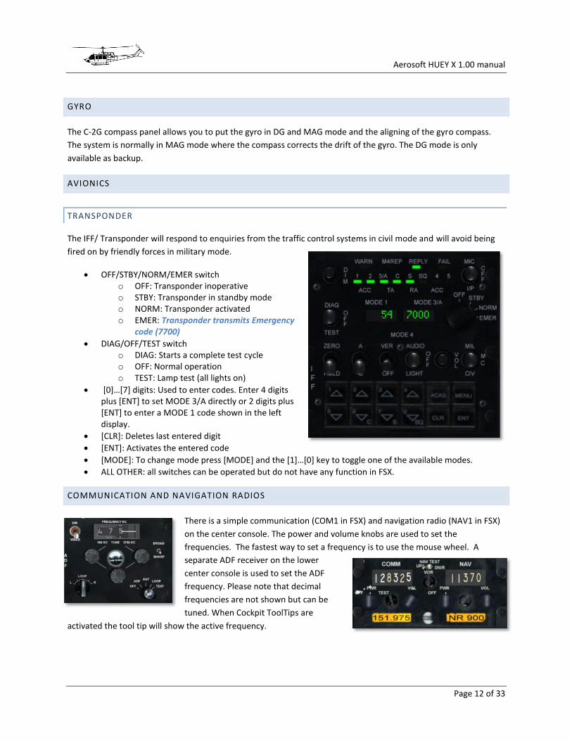
TRANSPONDER
The IFF/ Transponder will respond to enquiries from the traffic control systems in civil mode and will avoid being
fired on by friendly forces in military mode.
OFF/STBY/NORM/EMER switch o OFF: Transponder inoperative o STBY: Transponder in standby mode o NORM: Transponder activated o EMER: Transponder transmits Emergency
code (7700)
DIAG/OFF/TEST switch o DIAG: Starts a complete test cycle o OFF: Normal operation o TEST: Lamp test (all lights on)
[0]…[7] digits: Used to enter codes. Enter 4 digits plus [ENT] to set MODE 3/A directly or 2 digits plus [ENT] to enter a MODE 1 code shown in the left display.
[CLR]: Deletes last entered digit
[ENT]: Activates the entered code
[MODE]: To change mode press [MODE] and the [1]…[0] key to toggle one of the available modes.
ALL OTHER: all switches can be operated but do not have any function in FSX.
COMMUNICATION AND NAVIGATION RADIOS
There is a simple communication (COM1 in FSX) and navigation radio (NAV1 in FSX)
on the center console. The power and volume knobs are used to set the
frequencies. The fastest way to set a frequency is to use the mouse wheel. A
separate ADF receiver on the lower
center console is used to set the ADF
frequency. Please note that decimal
frequencies are not shown but can be
tuned. When Cockpit ToolTips are
activated the tool tip will show the active frequency.

Aerosoft HUEY X 1.00 manual
Page 13 of 33
PANELS AND GAUGES
In the virtual cockpit the [a] key cycles through the diverse views (note there is no 2D panel)
Pilot View
Center Console (front)
Center Console (aft)
Overhead Panel (front)
Overhead Panel (aft)
Copilot View
Observer View
State Selector panel
All controls, knobs and switches can be operated with the mouse using the following logic:
When a switch can only be toggled this is done with the left mouse button.
When a switch has more than two settings left mouse click moves to one side, right mouse click to the other side. The mouse wheel will function here as well.
All frequency setting knobs can be left clicked but are the use of the mouse wheel is strongly recommended.
Aerosoft HUEY X 1.00 manual
Page 14 of 33
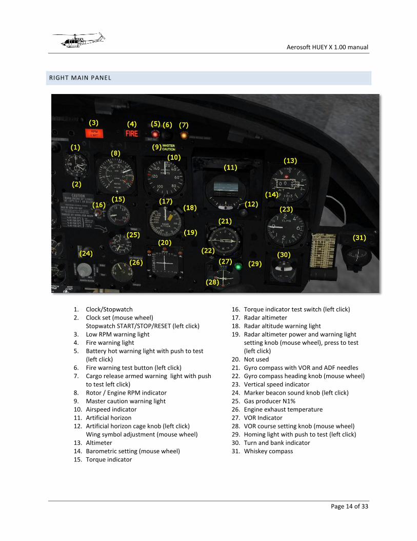
RIGHT MAIN PANEL
1. Clock/Stopwatch 2. Clock set (mouse wheel)
Stopwatch START/STOP/RESET (left click) 3. Low RPM warning light 4. Fire warning light 5. Battery hot warning light with push to test
(left click) 6. Fire warning test button (left click) 7. Cargo release armed warning light with push
to test left click) 8. Rotor / Engine RPM indicator 9. Master caution warning light 10. Airspeed indicator 11. Artificial horizon 12. Artificial horizon cage knob (left click)
Wing symbol adjustment (mouse wheel) 13. Altimeter 14. Barometric setting (mouse wheel) 15. Torque indicator
16. Torque indicator test switch (left click) 17. Radar altimeter 18. Radar altitude warning light 19. Radar altimeter power and warning light
setting knob (mouse wheel), press to test (left click)
20. Not used 21. Gyro compass with VOR and ADF needles 22. Gyro compass heading knob (mouse wheel) 23. Vertical speed indicator 24. Marker beacon sound knob (left click) 25. Gas producer N1% 26. Engine exhaust temperature 27. VOR Indicator 28. VOR course setting knob (mouse wheel) 29. Homing light with push to test (left click) 30. Turn and bank indicator 31. Whiskey compass

Aerosoft HUEY X 1.00 manual
Page 15 of 33
LEFT MAIN PANEL
1. Airspeed indicator
2. Artificial horizon
3. Artificial horizon cage (left click)
Wing symbol adjustment (mouse wheel)
4. Altimeter
5. Barometric setting knob (mouse wheel)
6. IFF code warning light with push to test (left click)
7. Radar altimeter
8. Radar altitude warning light
9. Radar altimeter power and warning light setting knob (mouse wheel)
10. Gyro compass with VOR and ADF needles
11. Vertical speed indicator
12. Turn and bank indicator
13. ILS indicator with course and glide slope indication
14. ILS test light with push to test (left click)
15. Homing indicator (not used)
16. Homing test light with push to test (left click)

Aerosoft HUEY X 1.00 manual
Page 16 of 33
CENTER CONSOLE AFT
1. ADF frequency setting
2. ADF power knob (left click)
3. 100 kHz setting knob (mouse wheel)
4. 10 kHz setting knob (mouse wheel)
5. 1 kHz setting knob with 0.1 kHz steps (mouse wheel)
6. Gyro compass source (left click)
7. Gyro compass align knob (mouse wheel)

Aerosoft HUEY X 1.00 manual
Page 17 of 33
CENTER CONSOLE FRONT
1. Transponder 2. Transponder power and mode (mouse
wheel) 3. COM radio frequency setting 4. COM radio power
(left click on bottom of knob) Frequency setting knob for whole MHz (mouse wheel)
5. COM radio frequency setting knob for fractional MHz (mouse wheel)
6. NAV radio frequency setting 7. NAV radio Power
(left click on bottom of knob) 8. Frequency setting knob for whole MHz
(mouse wheel) NAV radio frequency setting knob for fractional MHz ( mouse wheel)
9. Chip detect selector (left & right click with spring return)
10. Cable cutter Guard (right click) and switch (left click)
11. Force trim (left click) 12. Hydraulic Control (left click) 13. Defrost lever (left click) 14. Warning lights
15. Master warning light acknowledge (right click) and Warning light test switch (left click)
16. Low RPM sound switch (left click) 17. Main fuel valve (left click) guard (right click) 18. Start fuel valve (left click) 19. Left internal aux fuel switch (left click) 20. Right internal aux fuel switch (left click) 21. Engine de-ice switch (left click) 22. Governor emergency switch (left click) 23. Search light power and stow switch
(left / right click) 24. Search light position control hat switch
(left click up, down, left and right) 25. Landing light Guard (left click)
Power switch (left click) 26. Landing light extend / retract switch
(left click) 27. Governor RPM increase / decrease switch
(left click and drag) 28. Idle release button (left click) 29. Starter - hidden beneath the collective
(left click on marked position) 30. Throttle (mouse wheel / hardware controller
propeller lever)
Aerosoft HUEY X 1.00 manual
Page 18 of 33
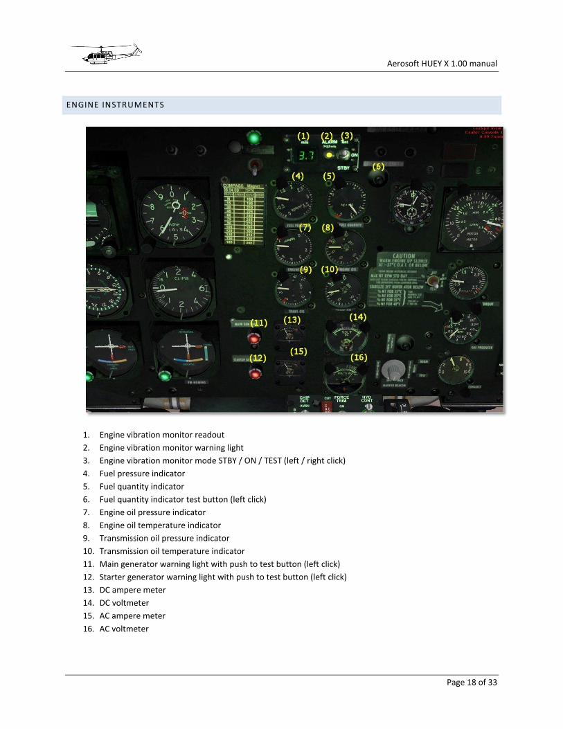
ENGINE INSTRUMENTS
1. Engine vibration monitor readout
2. Engine vibration monitor warning light
3. Engine vibration monitor mode STBY / ON / TEST (left / right click)
4. Fuel pressure indicator
5. Fuel quantity indicator
6. Fuel quantity indicator test button (left click)
7. Engine oil pressure indicator
8. Engine oil temperature indicator
9. Transmission oil pressure indicator
10. Transmission oil temperature indicator
11. Main generator warning light with push to test button (left click)
12. Starter generator warning light with push to test button (left click)
13. DC ampere meter
14. DC voltmeter
15. AC ampere meter
16. AC voltmeter
Aerosoft HUEY X 1.00 manual
Page 19 of 33
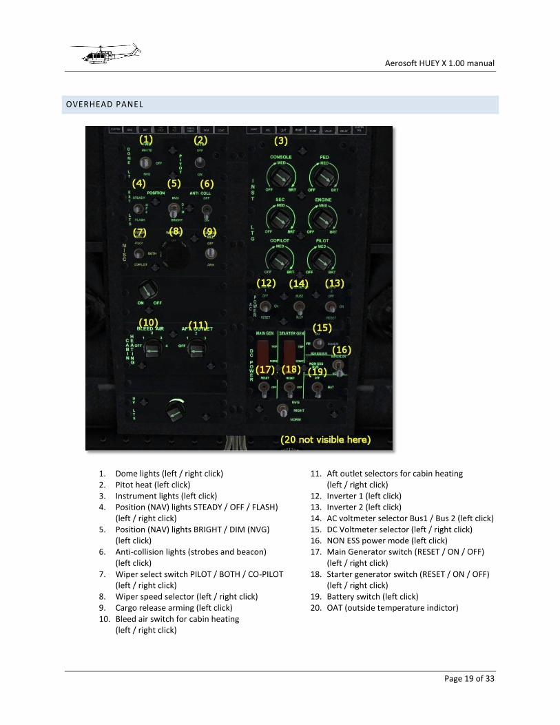
OVERHEAD PANEL
1. Dome lights (left / right click) 2. Pitot heat (left click) 3. Instrument lights (left click) 4. Position (NAV) lights STEADY / OFF / FLASH)
(left / right click) 5. Position (NAV) lights BRIGHT / DIM (NVG)
(left click) 6. Anti-collision lights (strobes and beacon)
(left click) 7. Wiper select switch PILOT / BOTH / CO-PILOT
(left / right click) 8. Wiper speed selector (left / right click) 9. Cargo release arming (left click) 10. Bleed air switch for cabin heating
(left / right click)
11. Aft outlet selectors for cabin heating (left / right click)
12. Inverter 1 (left click) 13. Inverter 2 (left click) 14. AC voltmeter selector Bus1 / Bus 2 (left click) 15. DC Voltmeter selector (left / right click) 16. NON ESS power mode (left click) 17. Main Generator switch (RESET / ON / OFF)
(left / right click) 18. Starter generator switch (RESET / ON / OFF)
(left / right click) 19. Battery switch (left click) 20. OAT (outside temperature indictor)

Aerosoft HUEY X 1.00 manual
Page 20 of 33
CIRCUIT BREAKER PANEL
There are four circuitbreakers operational because they are used in the checklists.
1. Circuit breaker for Co-pilot windshield wiper (left click)
2. Circuit breaker for Pilot windshield wiper (left click)
3. Circuit breaker for Left fuel boost pump (left click)
4. Circuit breaker for Right fuel boost pump (left click)
Aerosoft HUEY X 1.00 manual
Page 21 of 33
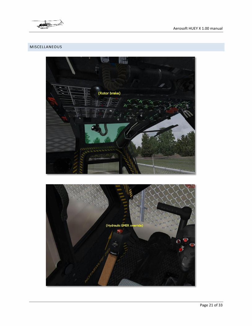
MISCELLANEOUS
Aerosoft HUEY X 1.00 manual
Page 22 of 33
OPERATING LIMITATIONS
TYPE OF OPERATION
The helicopter is certified for day and night operations in known non-icing conditions. The equipment in the
models we provide allows day and night IFR operations
AMBIENT AIR TEMPERATURE LIMITATIONS
The maximum sea level ambient temperature for operations is +53°C. The minimum sea level ambient
temperature for operations is -52°C. Engine de-icing and pitot heat has to be turned on at temperatures below 5°C
for flights in visible moisture. At temperatures above 5°C engine de-icing should not be used.
ALTITUDE LIMITATIONS
Maximum operating altitude is 20,000 feet pressure altitude. As oxygen equipment is not standard any operation
over 8,000 feet should be considered non-standard.
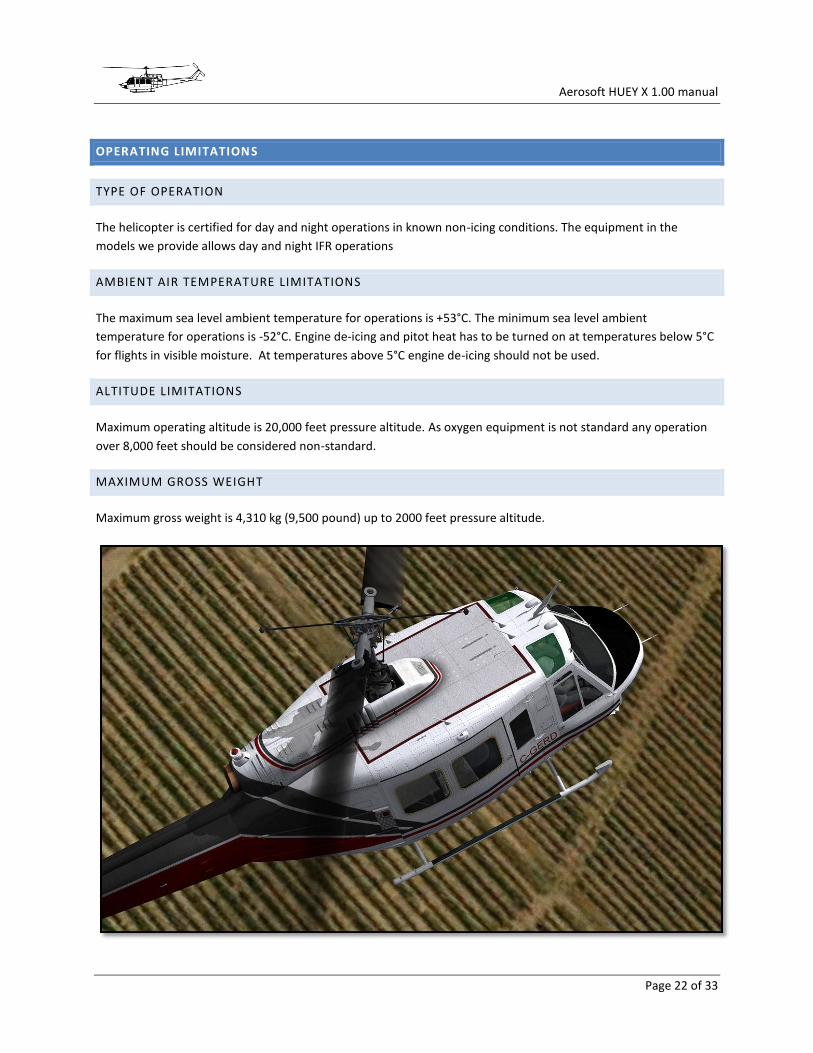
MAXIMUM GROSS WEIGHT
Maximum gross weight is 4,310 kg (9,500 pound) up to 2000 feet pressure altitude.

Aerosoft HUEY X 1.00 manual
Page 23 of 33
CHECKLISTS
Please note that the checklists are also available in formats suitable for tablets and smartphones.
INTERIOR CHECK
1. Flight Controls ........................................ FREE 2. HYD EMER OVER sw ............................... CHECK CLOSED COVER 3. SEARCH & LDG lt sw ............................... OFF 4. Avionics equipment ................................ OFF 5. C-2G compass slaving ............................. MAG 6. INT AUX FUEL sws ................................... OFF 7. DE-ICE sw ................................................ OFF 8. GOV sw ................................................... AUTO 9. START FUEL sw ....................................... ON 10. MAIN FUEL sw ........................................ ON 11. HOIST CABLE CUT ................................... CHECK CLOSED COVER 12. FORCE TRIM sw ...................................... ON 13. HYD CONT sw ......................................... ON 14. DEFROST lever ........................................ OFF 15. MARKER BEACON VOLUME knob ........... OFF 16. Engine vibration indicator ...................... STBY 17. Clock ....................................................... CHECK / SET 18. BIV-NORM-TEST sw ................................ NORM 19. Radar altimeter ...................................... OFF 20. Attitude indicators.................................. UNCAGED 21. Altimeter ................................................ SET 22. OAT gauge .............................................. CHECK 23. BLEED AIR selector ................................. OFF 24. Wipers .................................................... OFF 25. POSITION LIGHTS .................................... AS REQUIRED 26. ANTI COLLISION LIGHTS .......................... AS REQUIRED 27. DOME LIGHTS ......................................... AS REQUIRED 28. PITOT HTR sw ......................................... OFF 29. DC CB ...................................................... IN (EXCEPT RESCUE HOIST AND WINDSHIELD WIPERS) 30. INVTR 1 sw .............................................. OFF 31. INVTR 2 sw .............................................. OFF 32. AC BUS sw............................................... BUS 1 33. MAIN GEN sw ......................................... NORMAL (cover closed) 34. MAIN GEN CONTROL sw ......................... OFF 35. STARTER GEN sw .................................... START (cover closed) 36. STARTER GEN CONTROL sw .................... OFF 37. DC NON-ESS BUS sw ............................... NORMAL ON
Aerosoft HUEY X 1.00 manual
Page 24 of 33
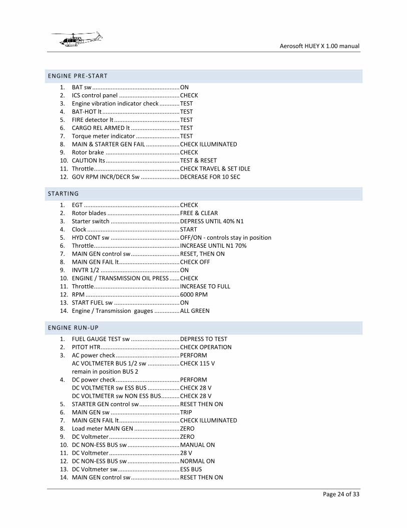
ENGINE PRE-START
1. BAT sw .................................................... ON 2. ICS control panel .................................... CHECK 3. Engine vibration indicator check ............ TEST 4. BAT-HOT lt .............................................. TEST 5. FIRE detector lt ....................................... TEST 6. CARGO REL ARMED lt ............................. TEST 7. Torque meter indicator .......................... TEST 8. MAIN & STARTER GEN FAIL .................... CHECK ILLUMINATED 9. Rotor brake ............................................ CHECK 10. CAUTION lts ............................................ TEST & RESET 11. Throttle ................................................... CHECK TRAVEL & SET IDLE 12. GOV RPM INCR/DECR Sw ....................... DECREASE FOR 10 SEC
STARTING
1. EGT ......................................................... CHECK 2. Rotor blades ........................................... FREE & CLEAR 3. Starter switch ......................................... DEPRESS UNTIL 40% N1 4. Clock ....................................................... START 5. HYD CONT sw ......................................... OFF/ON - controls stay in position 6. Throttle ................................................... INCREASE UNTIL N1 70% 7. MAIN GEN control sw ............................. RESET, THEN ON 8. MAIN GEN FAIL lt .................................... CHECK OFF 9. INVTR 1/2 ............................................... ON 10. ENGINE / TRANSMISSION OIL PRESS ...... CHECK 11. Throttle ................................................... INCREASE TO FULL 12. RPM ........................................................ 6000 RPM 13. START FUEL sw ....................................... ON 14. Engine / Transmission gauges ............... ALL GREEN
ENGINE RUN-UP
1. FUEL GAUGE TEST sw ............................. DEPRESS TO TEST 2. PITOT HTR ............................................... CHECK OPERATION 3. AC power check ...................................... PERFORM
AC VOLTMETER BUS 1/2 sw ................... CHECK 115 V remain in position BUS 2 4. DC power check ...................................... PERFORM
DC VOLTMETER sw ESS BUS ................... CHECK 28 V DC VOLTMETER sw NON ESS BUS........... CHECK 28 V 5. STARTER GEN control sw ........................ RESET THEN ON 6. MAIN GEN sw ......................................... TRIP 7. MAIN GEN FAIL lt .................................... CHECK ILLUMINATED 8. Load meter MAIN GEN ........................... ZERO 9. DC Voltmeter .......................................... ZERO 10. DC NON-ESS BUS sw ............................... MANUAL ON 11. DC Voltmeter .......................................... 28 V 12. DC NON-ESS BUS sw ............................... NORMAL ON 13. DC Voltmeter sw..................................... ESS BUS 14. MAIN GEN control sw ............................. RESET THEN ON

Aerosoft HUEY X 1.00 manual
Page 25 of 33
15. FUEL BOOST pump check ....................... PERFORM 16. DE-ICE .................................................... PERFORM 17. DE-ICE sw ................................................ ON
EGT ......................................................... CHECK INCREASE 18. DE-ICE sw ................................................ OFF
EGT ......................................................... CHECK DECREASE 19. Engine / Transmission gauges ................ ALL NORMAL 20. GOV RPM INCR/DECR test ...................... PERFORM
GOV RPM INCR/DECR sw ........................ MOVE THROUGH FULL RANGE GOV RPM INCR/DECR sw ........................ SET TO 6400-6600 N2 RPM 21. C-2G COMPASS ....................................... SYNCHRONIZE 22. Avionics check ........................................ PERFORM
IFF/SIF ..................................................... CHECK OPERATION VHF COM ................................................ CHECK OPERATION VHF NAV ................................................. CHECK OPERATION UHF/ADF ................................................. CHECK OPERATION MARKER BEACON ................................... CHECK OPERATION
BEFORE TAKE-OFF
1. Engine ..................................................... 6400-6600 N2 RPM 2. FUEL QUANTITY ...................................... CHECK 3. Instruments ............................................ CHECK 4. Radar altimeter ...................................... ON 5. Caution panel ......................................... CHECK (&reset) 6. OAT ......................................................... CHECK 7. PITOT HTR ............................................... AS REQUIRED 8. BLEED AIR selector ................................. AS REQUIRED 9. DE-ICE sw ................................................ AS REQUIRED 10. FORCE TRIM ............................................ AS REQUIRED
ADDITIONAL FOR IFR FLIGHTS, CHECK IN HOVER TAXI
11. Turn needle, heading compass............... CHECK 12. Vertical speed, altimeter ........................ CHECK 13. Attitude indicator ................................... CHECK 14. Turn and slip indicator ............................ BALL FREE 15. Airspeed indicator .................................. CHECK
BEFORE DEPARTURE
1. Avionics .................................................. SET/ ON 2. Navigation .............................................. SET 3. Hover power / takeoff power ................. CHECK 4. Fuel quantity .......................................... CHECK 5. Attitude indicators.................................. SET 6. Takeoff time ........................................... NOTE
Aerosoft HUEY X 1.00 manual
Page 26 of 33
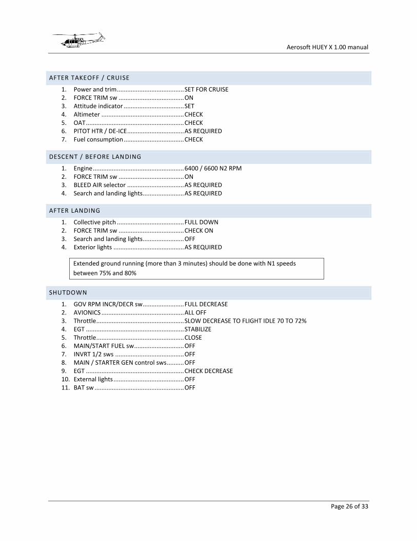
AFTER TAKEOFF / CRUISE
1. Power and trim ....................................... SET FOR CRUISE 2. FORCE TRIM sw ...................................... ON 3. Attitude indicator ................................... SET 4. Altimeter ................................................ CHECK 5. OAT ......................................................... CHECK 6. PITOT HTR / DE-ICE ................................. AS REQUIRED 7. Fuel consumption ................................... CHECK
DESCENT / BEFORE LANDING
1. Engine ..................................................... 6400 / 6600 N2 RPM 2. FORCE TRIM sw ...................................... ON 3. BLEED AIR selector ................................. AS REQUIRED 4. Search and landing lights ........................ AS REQUIRED
AFTER LANDING
1. Collective pitch ....................................... FULL DOWN 2. FORCE TRIM sw ...................................... CHECK ON 3. Search and landing lights ........................ OFF 4. Exterior lights ......................................... AS REQUIRED
Extended ground running (more than 3 minutes) should be done with N1 speeds
between 75% and 80%
SHUTDOWN
1. GOV RPM INCR/DECR sw ........................ FULL DECREASE 2. AVIONICS ................................................ ALL OFF 3. Throttle ................................................... SLOW DECREASE TO FLIGHT IDLE 70 TO 72% 4. EGT ......................................................... STABILIZE 5. Throttle ................................................... CLOSE 6. MAIN/START FUEL sw ............................. OFF 7. INVRT 1/2 sws ........................................ OFF 8. MAIN / STARTER GEN control sws .......... OFF 9. EGT ......................................................... CHECK DECREASE 10. External lights ......................................... OFF 11. BAT sw .................................................... OFF

Aerosoft HUEY X 1.00 manual
Page 27 of 33
APPENDIX A: THE AEROSOFT INSTALLER AND LAUNCHER
The new installer and launcher system has advantages for Aerosoft (it protects our copyrights better) and for the
customers (makes it easier to see what is installed and which updates are available. Using the new system is simple
and only adds a few steps to what was used before. However, there are four things that you have to keep in mind.
You need to be connected to the Internet while the installation and activation takes place (there is an offline option via email, more on that later).
You need to be logged on as Administrator on your system.
You need to understand that the product needs to be activated before it can be used. Scenery products will just not show until the files are activated and aircraft products will have other limitations.
You need to know the installed files are customized to your order. Multiple files of the product will be marked so if they ever ended up on the Internet we know where they came from.
After the SETUP.EXE is started you will see this screen (of course the actual product might differ):
Click [Next] to continue, you expected that right?
Aerosoft HUEY X 1.00 manual
Page 28 of 33
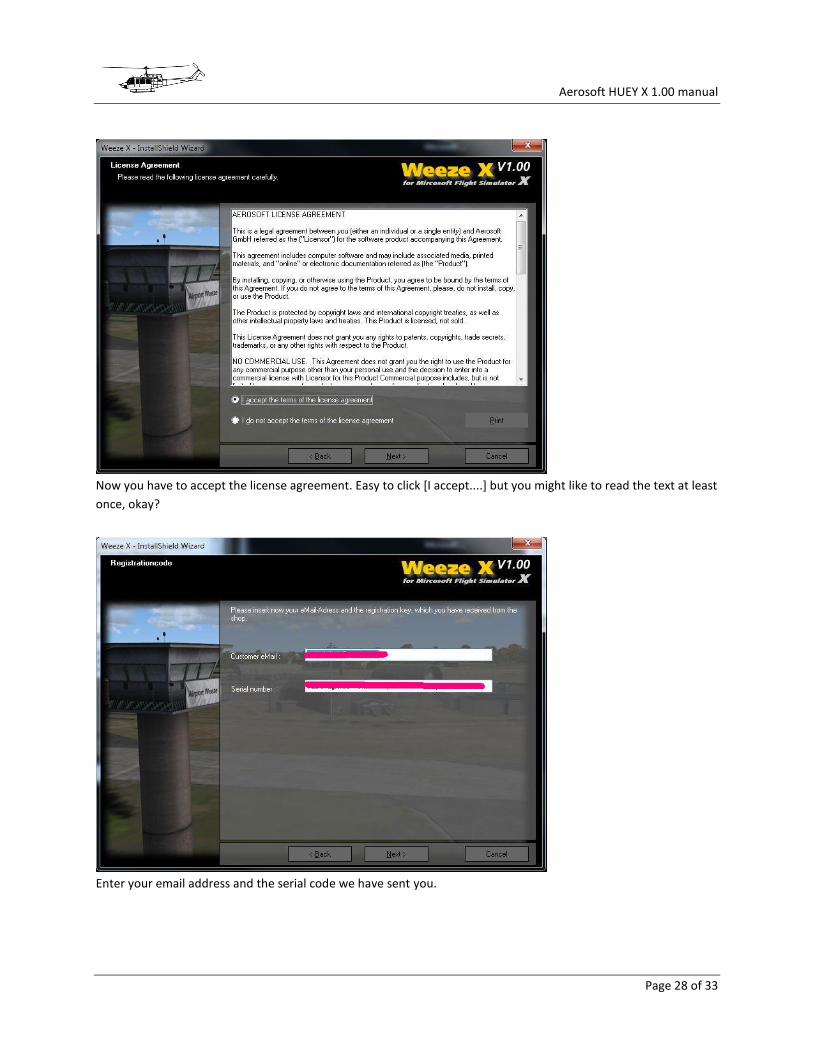
Now you have to accept the license agreement. Easy to click [I accept....] but you might like to read the text at least
once, okay?
Enter your email address and the serial code we have sent you.
Aerosoft HUEY X 1.00 manual
Page 29 of 33
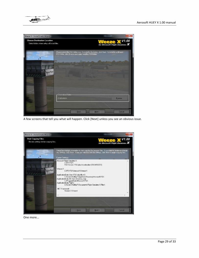
A few screens that tell you what will happen. Click [Next] unless you see an obvious issue.
One more...

Aerosoft HUEY X 1.00 manual
Page 30 of 33
The files are now installed. It will take a few seconds.
And you're done. Click [Finish] to close the installation part of getting the software in FSX.
Now Aerosoft Launcher will start and you will see this.
Aerosoft HUEY X 1.00 manual
Page 31 of 33
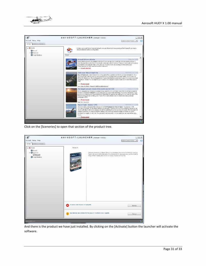
Click on the [Sceneries] to open that section of the product tree.
And there is the product we have just installed. By clicking on the [Activate] button the launcher will activate the
software.

Aerosoft HUEY X 1.00 manual
Page 32 of 33
Select the download shop you used, enter the email address used when buying and the serial code and click
[Online activation]. You will see the program contact the server and do its work. Note that only appropriate
information is sent. Product code, email address etc.
Eh voila, the product shows in green and you can now start FS to start enjoying the product.