content · packing, transport and storage all packing, lifting, handling, transport and unpacking...
TRANSCRIPT

1
Content Packing, Transport and Storage ......................................................................................................................... 2
Packing ........................................................................................................................................................... 2 Lifting and Handling ...................................................................................................................................... 2 Storage ........................................................................................................................................................... 2 Stacking .......................................................................................................................................................... 2 Opening .......................................................................................................................................................... 3 INTRODUCTION WARNING............................................................................................................. 3 THE SAFETY OF LIFTED VEHICLES....................................................................................................... 3 Conserving the manual ................................................................................................................................ 3 Laws ................................................................................................................................................................ 3
1. Abstract ......................................................................................................................................................... 5 2. Uses................................................................................................................................................................ 5 3. Important Technical Reference ............................................................................................................... 5 4. Working conditions: ................................................................................................................................... 5 5. Basic Structure of the Product ................................................................................................................ 6 6. Installation of the Safety Features ............................................................................................................. 6 7. Installation and Adjustment of the Equipment ....................................................................................... 7 8. Use and Operation ......................................................................................................................................... 8 9. Maintenance and Care ............................................................................................................................... 9 10. Common Problems and Solution Methods ......................................................................................... 10 11. Important Information for the User ................................................................................................... 10 12. Important Items .....................................................................................................................................11 13. Noise Declaration:................................................................................................................................11 14. Components chart: .....................................................................................................................................11

Packing, Transport and Storage
ALL PACKING, LIFTING, HANDLING, TRANSPORT AND UNPACKING ORERATIONS ARE
TO BE PERFORMED EXCLUSIVELY BY EXPERT PERSONNEL WITH KNOWLEDGE OF THE
VEHICLE LIFT AND THE CONTENTS OF THIS MANUL
Packing The lift of 2 post lift is shipped disassembled into following parts:
1. Complete command post, complete with carriage, hydraulic cylinder, upper arm, shot arm, lower
cover board, and so on.
The gross weight is 630kg. (Net weight is 610kg)
The lift of 2 post lift with clear floor is shipped disassembled into following parts:
1. Complete command post, complete with carriage, hydraulic cylinder, upper arm, shot arm, lower
cover board, and so on.
2. Second part of columns is packed into one piece in separating.
The gross weight is 670kg. (Net weight is 650kg)
Lifting and Handling The pack boxes may be lifted and moved with a lift truck (Fig.1).If either of the latter two are used ,
boxes must be harnessed with at least 2 slings.
Fig.1 Fig.2
Storage
Pack boxes always be kept in a covered, protected place, at a temperature between -10。And +40。
And must not be exposed to direct sunlight and must not be caught in the rain.
Stacking
The type of packing allows the possibility of stacking up to 3 crates.
Up to 3 crates may be stacked one upon the other on lorries or in containers if property positioned and
2

provided they are restrained to prevent falling.
Opening
When the crates arrive, check that the machine has not been damaged during transport and that all
parts listed are present. The crates must be opened using all possible precautionary measure to avoid
damaging the machine or its parts. Make sure that parts do not fall from the crate during opening.
INTRODUCTION WARNING
This manual has been prepared for workshop personnel expert in the use of the lift (operator) and
technicians responsible for routine maintenance (maintenance fitter): read the manual before carrying
out any operation with the lift and /or the packing. This manual contains important information
regarding:
THE PERSONAL SAFETY OF operators and maintenance workers
THE SAFETY OF LIFTED VEHICLES
Conserving the manual
The manual is an integral part of the lift, which it should always accompany even if the unit is sold .The
manual, must be kept in the vicinity of the lift in an easily accessible place so that the operator and
maintenance staff must be able to locate and consult the manual quickly at any time.
ATTENTIVE AND REPEATED READING OF CHAPTER 3, WHICH CONTAINS IMPORTANT
INFORMATION AND SAFETY WARNINGS, IS PARTICULARLY RECOMMENDED.
Lift rack has been designed and built in compliance with the following:
Laws
Machinery Directives: 2006/42/EC,Low volt directive 2006/95/EC and applicable standards:EN
60204-1:2006+ A1:2009,EN1493:1998+ A1:2008.
The lifting, transport, unpacking, assembling, installation, starting up, initial adjustment and testing, the
work relate to EXTRAORDINARY maintenance, repair, overhauls, transport and dismantling of the lift
must be performed by specialist personnel from the LICENSED DEALER or an SEVICE CENTRE
authorized by the manufacturer (see authorized dealer on frontispiece).
The manufacturer declines all responsibility for injury to persons or damage to vehicles or objects when
any of the above mentioned operations have been performed by unauthorized personnel or when the
rack has been subject to abuse.
3

4
This manual indicates only the operative and safety aspects that may prove useful to the operator and
maintenance works better understanding the structure and operation of the lift and for best use of the
lift.
In order to understand the terminology used in this manual, the operator must have specific experience
in workshop, service, maintenance and repair activities, the ability to interpret correctly the drawings
and descriptions contained in the manual and be acquainted with the general and specific safety rules
relevant to the country in which the machine has been installed.
The same applies to the maintenance fitter, who must also possess specific and specialized knowledge
(mechanical, engineering) needed to perform the operations described in the manual in complete
safety.
The words “operator” and “maintenance fitter” used in this manual are construed as follows:
OPERATOR: person authorized to use the lift.
MAINTENANCE: person authorized for routine maintenance of the lift.
The end user can only use the machine in correct way as defined in instruction.
Loose clothes shall not be used protection cap shall also be used for long hair person, etc.
Lubricate the machine periodically according to the manual.
We bend ourselves to improve our quality and update technical
standard, we would not give any other information if there were any
changes.
5
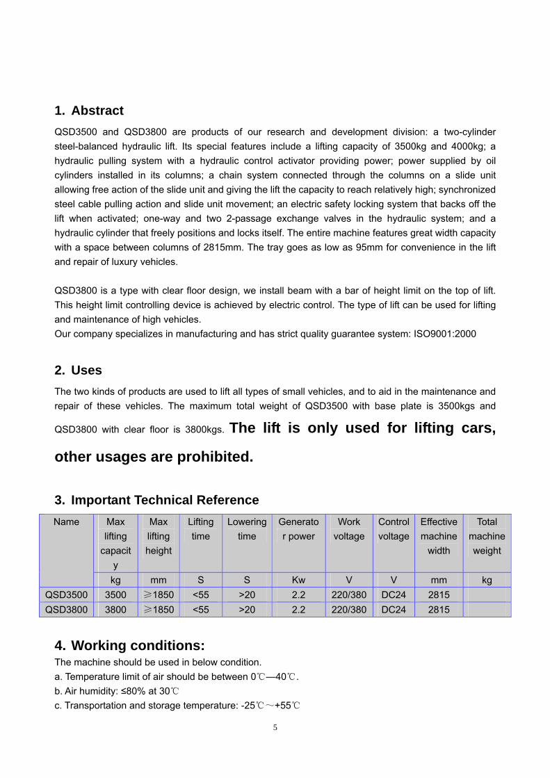
1. Abstract QSD3500 and QSD3800 are products of our research and development division: a two-cylinder steel-balanced hydraulic lift. Its special features include a lifting capacity of 3500kg and 4000kg; a hydraulic pulling system with a hydraulic control activator providing power; power supplied by oil cylinders installed in its columns; a chain system connected through the columns on a slide unit allowing free action of the slide unit and giving the lift the capacity to reach relatively high; synchronized steel cable pulling action and slide unit movement; an electric safety locking system that backs off the lift when activated; one-way and two 2-passage exchange valves in the hydraulic system; and a hydraulic cylinder that freely positions and locks itself. The entire machine features great width capacity with a space between columns of 2815mm. The tray goes as low as 95mm for convenience in the lift and repair of luxury vehicles. QSD3800 is a type with clear floor design, we install beam with a bar of height limit on the top of lift. This height limit controlling device is achieved by electric control. The type of lift can be used for lifting and maintenance of high vehicles. Our company specializes in manufacturing and has strict quality guarantee system: ISO9001:2000
2. Uses The two kinds of products are used to lift all types of small vehicles, and to aid in the maintenance and repair of these vehicles. The maximum total weight of QSD3500 with base plate is 3500kgs and
QSD3800 with clear floor is 3800kgs. The lift is only used for lifting cars,
other usages are prohibited.
3. Important Technical Reference Max lifting
capacity
Max lifting height
Lifting time
Lowering time
Generator power
Work voltage
Control voltage
Effective machine
width
Total machine weight
Name
kg mm S S Kw V V mm kg QSD3500 3500 ≥1850 <55 >20 2.2 220/380 DC24 2815 QSD3800 3800 ≥1850 <55 >20 2.2 220/380 DC24 2815
4. Working conditions: The machine should be used in below condition. a. Temperature limit of air should be between 0℃—40 .℃ b. Air humidity: ≤80% at 30℃ c. Transportation and storage temperature: -25℃~+55℃

d. Height above sea level: ≤2000m.
3500kg Express the rated load is 3500kg,don’t allow the lift load weigh excess 3500kg.
3800kg Express the rated load is 3800kg,don’t allow the lift load weigh excess 3800kg.
This symbol express attention should be taken for electrical hazards
This symbol expresses the earth connecting point.
5. Basic Structure of the Product Three parts of the product:
The mac★ hine is comprised of: main columns, supporting columns, cradle, lubricant stand, safety system and fixed skeleton, bottom plate or top beam etc. (Diagram 1, 2)
The electric control system is comprised of various electrical components that control the vari★ ous movements of the lift. (Diagram 3)
The hydraulic control system is comprised of a hydraulic pump activator, hydraulic cylinder, pipes and ★
other various components to aid in the various functions of the lift. (Diagram 4)
6. Installation of the Safety Features 6.1 Safety Stop Mechanism Inside each of the main and support columns is an electric safety stop feature. It is comprised of electro-magnetized steel, locking plate, lubricated lift collar safety plate, and support blocks on each column. (See Diagram 7) 6.2 Safety Stop Movement Fundamentals The locking plate relies on the weight and angle of each of the end faces, the entire top face adhering to mounting plate. When the collar rises, the angled mounting plate pushes open the locking plate to ascertain a certain height. When the collar becomes stuck in operation, or when the speed of descent produces unsafe circumstances, the locking plate block fits inside the aperture in the mounting plate, stopping the lift from further descent and activating the safety mechanism (see Diagram 7). 6.3 Adjustment of the Safety Mechanism 6.3.1 Adjustment of the magnetized axle core screw cap moves the locking plate from its natural state to insert into the groove of the mounting plate (with an empty load, ensure that the block can insert into the base of the groove of the mounting plate). When the lubricated stand is rising, you will be able to clearly hear a clacking inside the two columns. 6.3.2 When the magnetized steel is being drawn, check the two mounting plates are completely 6
7
separated. Ensure that the main and supporting columns are separating at the same time, otherwise this could prove very unsafe.
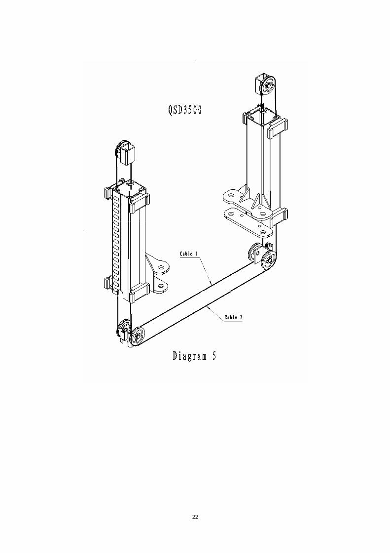
7. Installation and Adjustment of the Equipment 7.1 Installation should be carried out by trained employees of the manufacturing company. 7.2 The installation site should have 380V and 50Hz 3-phase power supply and reliable ground wires. 7.3 The incoming line should have 20A safety installation and a power supply switch. The minimum wire section area is 2.5 square millimeters. 7.4 The lift’s foundation has the following requirements: the concrete should not be lower than 250 grades; the area of the foundation should be 3645mm long ×800mm wide × >250mm thick. (see Diagram 8) 7.5 Installation Steps 7.5.1 When the concrete has solidified at the proper thickness, install the two columns into the floor of the installation site. Check and measure the dimensions and move into the proper place as needed by the user. After ensuring that the columns and floor are perpendicular, use steel plates and concrete to fill in any gaps between the base plate and floor. Use M18*160 anchor bolts to secure the base plate. 7.5.2 Lift and lock the two slide units into the first locking position. Connect the two synchronized steel cables according to needs (see Diagram 5,6). Adjust nuts (tighten the cable in position so the last thread screws against the nut, save the longer screws), and adjust the tension in the cables so that they are in the best position. 7.5.3 Connect the hydraulic system pipeline. (Diagram 9) 7.5.4 Add the oil: 10 Liters of Hydraulic Oil #46 in summer, # 32 in winter. 7.5.5 Affix the flat-ranged chain in the most logical position. Bring the slide blocks as low as they can go giving the cradle room to sway unobstructed but not sliding across the ground. When the product comes out of the factory, this first step should have already been set. (Diagram 5) 7.5.6 Lubricate the sliding blocks and grooves. (Use Formula 2 Grease) 7.6 Test for problems. 7.6.1 Preparing the vehicle. Before trying a vehicle on the lift, give the equipment a thorough check. Check that all connections are tight and reliable. Make sure the levers operate smoothly and that the ends of the hydraulic pipes are fastened securely. Check that the power source is adequate, and that the ground wire is reliable. The generator should turn in a direction consistent with that of the gear pump. When the ‘lock’ button is pressed on the operating lever, the two magnets in the columns should be moving together. 7.6.2 Operation with an Empty Load Check that the two sliding blocks are moving together and meet requirements. Regulate the tension in the steel cables so they meet requirements. The core axle line in the hydraulic cylinders should be equal to the core axle line in the columns (if not, adjust). The movement of the sliding blocks should be normal. The hydraulic pipeline should be free of leakage. The locking installation should be normally regulated, without any obstructions. Raise and lower two times.
8
7.6.3 Loading operation: If all is working order with an empty load, move a car onto the lift. Repeatedly raise and lift the vehicle, first bringing it to about 1000mm, checking each working part of the lift and adjusting as needed. If everything is up to standard, raise the lift to a fixed height and lower, and then repeat.
NOTE: After the lift has been installed a debugged, it can be used
for normal operation.
8. Use and Operation 8.1 Preparation After the cradle has swiveled back against the slides of the columns, drive the car up on the lift and into a suitable position. Rotate the cradle around and move the adjustable arms and the height of the chassis. Make sure the vehicle’s weight is evenly dispersed when propping it up. 8.2 Raising With the power source connected, turn ‘0’ position to ‘1’ position, hit the button and raise the vehicle. When the vehicle has risen 100-150mm off the ground, release the button to stop the lift. Rock the car to check that it is resting firm and steady on the cradle. Then hit the starter button again and raise the car to the required position. 8.3 Stopping Release the lift ‘UP’ button and allow the lift to stop. 8.4 Locking Press ‘Lock up’ button again and again for several seconds. When the sliding blocks have been locked, there is no need to hold down the button for a long period of time. To avoid the chain wheels from dropping too much, allow the chain to spin off empty. 8.5 Lowering Press the “Down” button, the lift raises first (time relay KT works), two-position three –way magnetic valve works to open the air cylinders and then the safety unlocks, for 1 or 2 seconds delay the magnetic valve works to descend, at the same time motor stops. 8.6 Lowering from limited height to the lowest: When lubricant stands descend to the limit switch, lift stops. Users check anywhere around lift and make everything normal and in security condition, then press “Parking” button the lubricant stands continue to descend.

9
Pay Attention during Operation: Before lifting the vehicle, be sure to adjust the height of the chassis, making sure the contact points are propping area. You must support the car on its skirt or bridge by positioning the center of the rubber chassis, so that the support area is perfectly centered. When the vehicle leaves the ground (100-150mm), rock the car a bit checking that lift is safe to operate. No one should be allowed underneath the car when the lift is in operation. When the lift has reached the required height, it must then be set in the safety position. Employees can then set up for work. Before the car is lowered, make sure everything is cleaned up below the car, the collar, and on the ground below the cradle. The entire work area should be cleaned up. Each week check each of the movable parts, lubricate the sliding blocks and ensure that the operating parts are lubricated and positioned properly. Bring the lift collar to its lowest position, checking the oil in the oil tank. Make sure the tank is filled 80% of the way. If meet any troubles unsolved please contact after-sales service department of our company or our local agency.
9. Maintenance and Care 9.1 Maintaining Cleanliness The lift should be frequently wiped down to maintain cleanliness. Before wiping, first cut the power supply. The work area about the lift should be swept up. If large amounts of dirt should accumulate, this will accelerate the rate of wear-and-tear on the machine and reduce its natural life span. 9.2 Regular Check-ups 9.2.1 Check the safety features of the lift every day before work. The magnets should be operating normally, the locking plate should be in position, the mounting plate of the lift collar should be free of damage, etc. If you discover something abnormal, make prompt adjustments, repairs or changes. 9.2.2 Every day, check that the space between the collar chain and the hydraulic cylinders is correct. Check if the flat-ranged chain and the nut connecting it to the collar have become loose or detached. 9.2.3 Connections to the steel cable should be normal and the cable should have proper tension.

10
9.3 Maintenance of the Hydraulic System 9.3.1 Cleaning, Oil Change Three months after the first full usage of the lift, clean out the oil tank and change the oil. Once per six months afterwards, clean the hydraulic system and change the oil. 9.3.2 Replacing the Seals After the lift has been used for a period of time, if you discover any oil leakage, make a thorough inspection. If the leakage is due to from wear of the seals, then replace parts immediately following regulations.
10. Common Problems and Solution Methods Trouble Cause Solution
Generator does not workThe power source or power equipment is malfunctioning
Check the power source and other electrical components,
check fuses Pistons have lost effectiveness Fix the pistons
Pipes are leaking oil Change the seals and tighten
the nuts on the connection In working mode, the collar automatically
lowers Seals on the hydraulic cylinders have lost effectiveness
Change the seals
The oil filter is stopped up Clean the oil filter Air has entered the hydraulic
system Lift the collar to max height, keep it there for 2-3 seconds The hydraulic system
makes abnormal sounds The space between the sliding blocks and columns are not
lubricated Add lubrication
The collar creeps when raising and lowering
The space between the sliding blocks and the columns is too
narrow
Select sliding blocks that will leave between a 1.5 and 2.5mm gap between the
blocks and column The main and
supplementary lift support mechanisms don’t move
together
The equilibrium cables are stretched out after use, losing their
tension
Adjust the nut on the steel cables, adding tension
11. Important Information for the User 11.1 Important Information Regarding Purchase of the Machine Before purchasing this lift, make sure you clearly understand the product’s use, feature, safety conditions, operation adjustments, etc. If there are any quality problems during shipping, installation or maintenance, please promptly contact the manufacturing company or a specializing agency.
11
11.2 Quality Assurance after Opening the Product If after opening the packaging, you notice that the product and accessories and the installation list do not match, please promptly contact the purchasing department. 11.3 Foundation The dimensions for the foundation of this product must be in accordance with those outlined by the manufacturing factory. The cement grade should be no less than #500. Concrete strength should be no
less than 250 grades. If you cannot meet this company’s requirements for
foundation strength, any problems resulting are the user’s responsibility. 11.4 Returning Documents Once the customer has purchased the equipment, should the need arise he/she should promptly fill out the warranty card and return to the manufacturing company. The company will enter information into the computer for prompt service.
12. Important Items 12.1 Before using this product, please carefully read the operating instructions in this manual. 12.2 Turn on the power switch. The power light will go on, then can use the machine. 12.3 In order to protect electrical components we choose DC 24V to control open locks.
13. Noise Declaration:
We hereby certify that the noises of lifts we produce can not exceed 80db when loading. Company Quality Test Department
14. Components chart: The chart is only used for maintenance and after-sales service, other usage are
not allowed.

No. Name QTY 1 Top plate 2 2 Main column and supplementary column 1 for each 3 Rope wheel B 2 4 Rope wheel D 4 5 Support of limit switch 1 6 Limit switch 7120 1 7 Cover of magnet 4 8 Magnet 4 9 Lock plate 4
10 Block 4 12
13
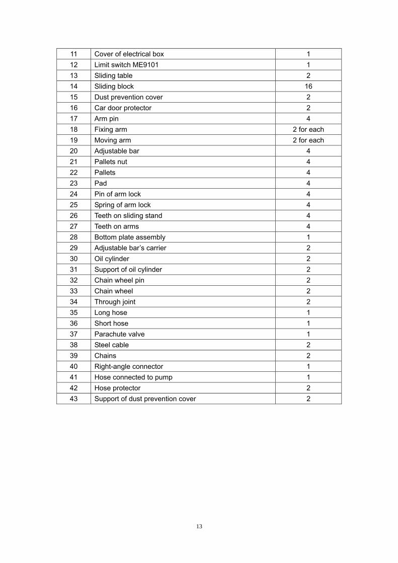
11 Cover of electrical box 1 12 Limit switch ME9101 1 13 Sliding table 2 14 Sliding block 16 15 Dust prevention cover 2 16 Car door protector 2 17 Arm pin 4 18 Fixing arm 2 for each 19 Moving arm 2 for each 20 Adjustable bar 4 21 Pallets nut 4 22 Pallets 4 23 Pad 4 24 Pin of arm lock 4 25 Spring of arm lock 4 26 Teeth on sliding stand 4 27 Teeth on arms 4 28 Bottom plate assembly 1 29 Adjustable bar’s carrier 2 30 Oil cylinder 2 31 Support of oil cylinder 2 32 Chain wheel pin 2 33 Chain wheel 2 34 Through joint 2 35 Long hose 1 36 Short hose 1 37 Parachute valve 1 38 Steel cable 2 39 Chains 2 40 Right-angle connector 1 41 Hose connected to pump 1 42 Hose protector 2 43 Support of dust prevention cover 2

No. Name QTY 1 Top plate 2 2 Main column and supplementary column 1 for each 3 Rope wheel B 4 4 Rope wheel D 2 5 Support of limit switch 1
14

15
6 Limit switch 7120 1 7 Cover of magnet 4 8 Magnet 4 9 Lock plate 4 10 Block 4 11 Cover of electrical box 1 12 Limit switch ME9101 1 13 Sliding table 2 14 Sliding block 16 15 Dust prevention cover 2 16 Car door protector 2 17 Arm pin 4 18 Fixing arm 2 for each 19 Moving arm 2 for each 20 Adjustable bar 4 21 Pallets nut 4 22 Pallets 4 23 Pad 4 24 Pin of arm lock 4 25 Spring of arm lock 4 26 Teeth on sliding stand 4 27 Teeth on arms 4 28 Top beam assembly A 1 29 Top beam assembly B 1 30 Oil cylinder 2 31 Support of oil cylinder 2 32 Chain wheel pin 2 33 Chain wheel 2 34 Parachute valve 2 35 Long hose 1 36 Short hose 1 37 T connector 1 38 Steel cable 2 39 Chains 2 40 Right-angle connector 1 41 Hose connected to pump 1 42 Hose protector 2 43 Support of dust prevention cover 2 44 Turning support 1 45 Sliding support 1 46 Limit bar 1 47 Limit bar sponge 1 48 Limit switch LX19-001 1 49 Second part of post assembly 2

Layout of lift with base plate type
16

Layout of lift with clear floor type
17

Electrical system of lift with base plate type
18

Electrical system of lift with clear floor type
19

Hydraulic system of lift with base plate type
20

Hydraulic system with clear floor type
21
22
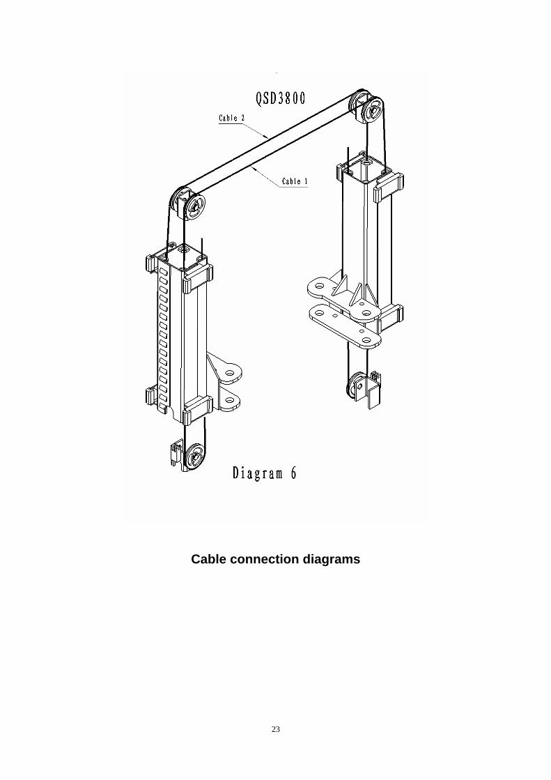
Cable connection diagrams
23

Safety lock diagrams
24

Note: Cement,cracked stone, sand mixture should be in the proportion 1:3:5 Cement:#350 Minimum hardening time is 20 days Pour the mortar once, leave no holes.
Foundation diagram
25
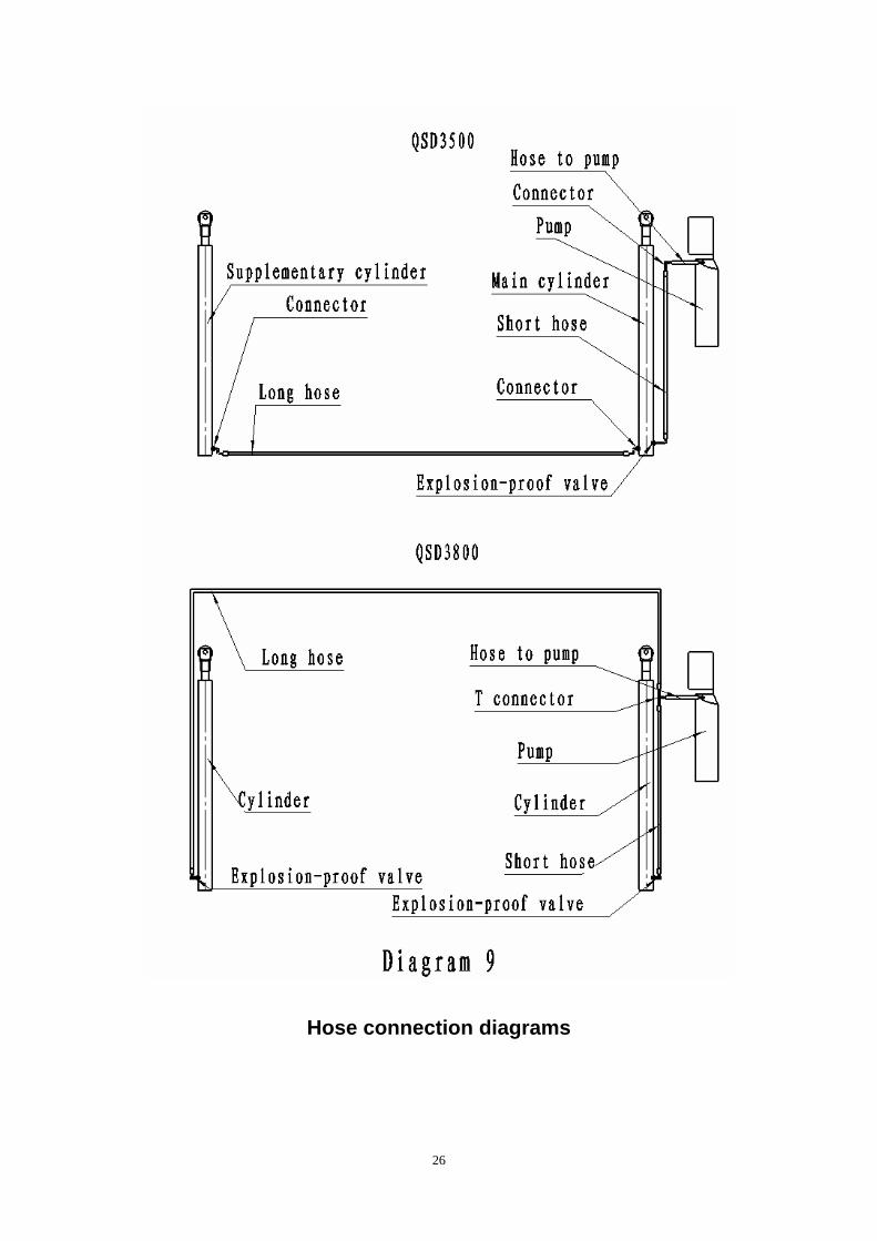
Hose connection diagrams
26