constructive vs. destructive interference; coherent vs ...constructive vs. destructive interference;...
TRANSCRIPT

Constructive vs. destructive interference; Coherent vs. incoherent interference
Waves that combine in phase add up to relatively high irradiance.
Waves that combine 180° out of phase cancel out and yield zero irradiance.
Waves that combine with lots of different phases nearly cancel out and yield very low irradiance.
=
=
=
Constructive interference (coherent)
Destructive interference (coherent)
Incoherent addition
Source: Tribino, Georgia Tech
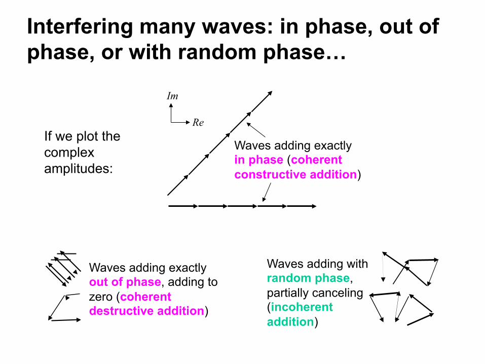
Interfering many waves: in phase, out of phase, or with random phase…
Waves adding exactly in phase (coherent constructive addition)
Waves adding with random phase, partially canceling (incoherent addition)
If we plot the complex amplitudes:
Re
Im
Waves adding exactly out of phase, adding to zero (coherent destructive addition)

The Irradiance (intensity) of a light wave!
The irradiance of a light wave is proportional to the square of the electric field:
I = 1
2 cε!E0~
2
!"E0
2=!E0x !
E0x* +!E0 y !
E0 y* +!E0z !
E0z*
This formula only works when the wave is of the form:
where:
!E !r ,t( ) = Re
"
!E0 exp i
!k ⋅ !r −ω t( )$
%&'
or:
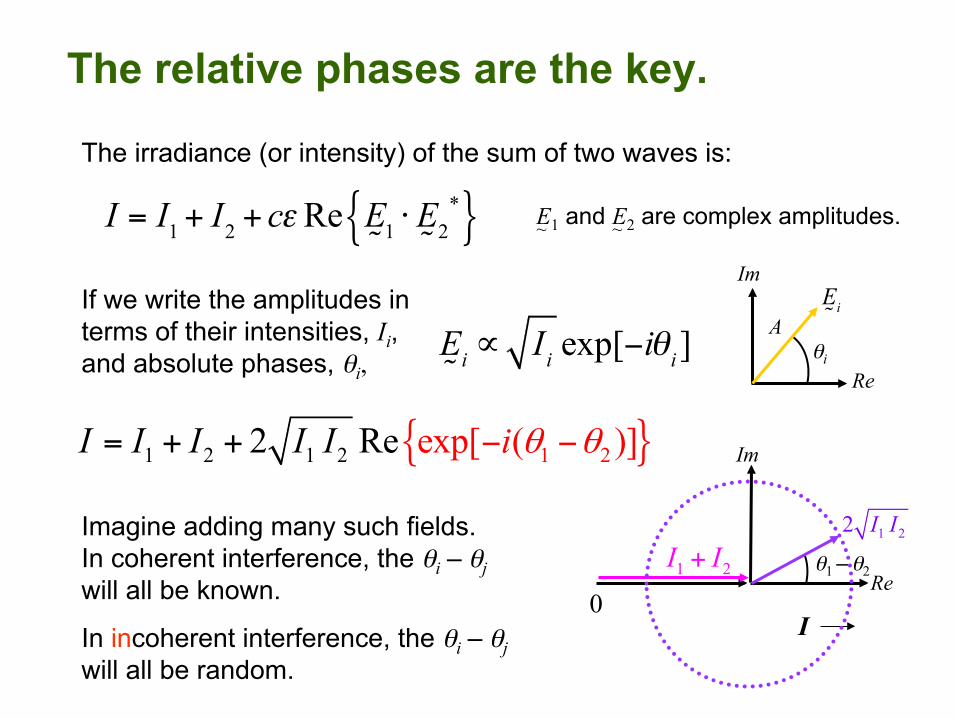
The relative phases are the key.
I = I1+ I2 + cεRe
!E1 ⋅ !
E2*{ }
The irradiance (or intensity) of the sum of two waves is:
If we write the amplitudes in terms of their intensities, Ii, and absolute phases, θi,
{ }2 1 21 1 22 Re exp[ ( )]I I I I iI θ θ− −= + +
!Ei ∝ Ii exp[−iθi]
Imagine adding many such fields. In coherent interference, the θi – θj will all be known.
In incoherent interference, the θi – θj will all be random.
Re
Im
A θi
!Ei
Re
Im
θ1 – θ2
1 22 I I
I 0
1 2I I+
E1 and E2 are complex amplitudes. ~ ~

Adding many fields with random phases
Itotal = I1 + I2 + … + In
I1, I2, … In are the irradiances of the various beamlets. They’re all
positive real numbers and they add.
Itotal = I1+ I2 + ...+ IN + cεRe
!E1 !
E2* +!E1 !
E3* + ...+
!EN−1 !
EN*{ }
We find:
!Etotal = [
!E1+ !
E2 + ...+!EN ] exp[i(
"k ⋅ "r −ω t)]
Ei Ej* are cross terms, which have the
phase factors: exp[i(θi-θj)]. When the θ’s are random, they cancel out!
Re
Im All the relative phases
exp[ ( )]i ji θ θ− exp[ ( )]k li θ θ−
The intensities simply add! Two 20W light bulbs yield 40W.
I1+I2+…+IN

Newton's Rings Get constructive interference when an integral number of half wavelengths occur between the two surfaces (that is, when an integral number of full wavelengths occur between the path of the transmitted beam and the twice reflected beam).
This effect also causes the colors in bubbles and oil films on puddles.
You see the color λ when constructive interference
occurs.
L
You only see bold colors when m = 1 (possibly 2). Otherwise the variation with λ is too fast for the eye to resolve.

Newton's Rings Animation - http://extraphysics.com/java/models/newtRings.html
( )22 2x R d R+ − =

Anti-reflection Coatings
Notice that the center of the round glass plate looks like it’s missing. It’s not! There’s an anti-reflection coating there (on both the front and back of the glass). Such coatings have been common on photography lenses and are now common on eyeglasses. Even my new watch is AR-coated!

The irradiance when combining a beam with a delayed replica of itself has fringes.
Suppose the two beams are E0 exp(iωt) and E0 exp[iω(t-τ)], that is, a beam and itself delayed by some time τ :
The irradiance is given by:
I = I1+ cεRe
!E1 ⋅ !
E2*{ }+ I2
I = 2I0 + cεRe
!E0 exp[iωt]⋅
!E0
* exp[−iω(t −τ )]{ }
= 2I0 + cεRe
!E0
2exp[iωτ ]{ }
= 2I0 + cε
!E0
2cos[ωτ ]
I = 2I0 +2I0 cos[ωτ ]
I “Bright fringe” “Dark fringe”
τ

Varying the delay on purpose Simply moving a mirror can vary the delay of a beam by many wavelengths.!
Since light travels 300 µm per ps, 300 µm of mirror displacement yields a delay of 2 ps. Such delays can come about naturally, too.!
Moving a mirror backward by a distance L yields a delay of:!
€
τ = 2 L /cDo not forget the factor of 2!!Light must travel the extra distance !to the mirror—and back!!
Translation stage!
Input !beam!E(t)
E(t–τ)
Mirror!Output !beam!
2 / 2L c k Lωτ ω= =
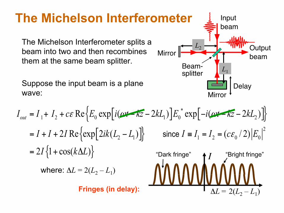
The Michelson Interferometer
Beam-!splitter!
Input!beam!
Delay!
Mirror!
Mirror!
Fringes (in delay):
[ ] [ ]{ }[ ]{ }
{ }
*1 2 0 1 0 2
22 1 1 2 0 0
Re exp ( 2 ) exp ( 2 )
2 Re exp 2 ( ) ( / 2)
2 1 cos( )
outI I I c E i t kz kL E i t kz kL
I I I ik L L I I I c E
I k L
ε ω ω
ε
= + + − − − − −
= + + − ≡ = =
= + Δ
since
The Michelson Interferometer splits a beam into two and then recombines them at the same beam splitter. Suppose the input beam is a plane wave:
L1
where: ΔL = 2(L2 – L1)
L2 Output!beam!
I “Bright fringe” “Dark fringe”
ΔL = 2(L2 – L1)
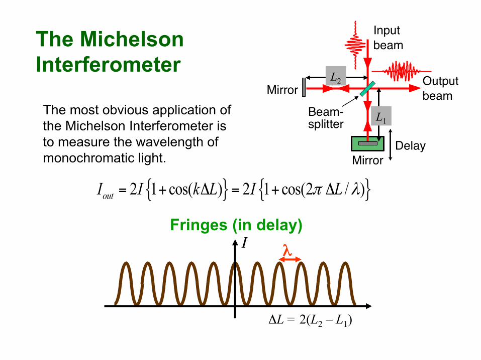
The Michelson Interferometer
Beam-!splitter!
Input!beam!
Delay!
Mirror!
Mirror!
The most obvious application of the Michelson Interferometer is to measure the wavelength of monochromatic light.
L1
L2 Output!beam!
{ } { }2 1 cos( ) 2 1 cos(2 / )outI I k L I Lπ λ= + Δ = + Δ
Fringes (in delay) I
ΔL = 2(L2 – L1)
λ
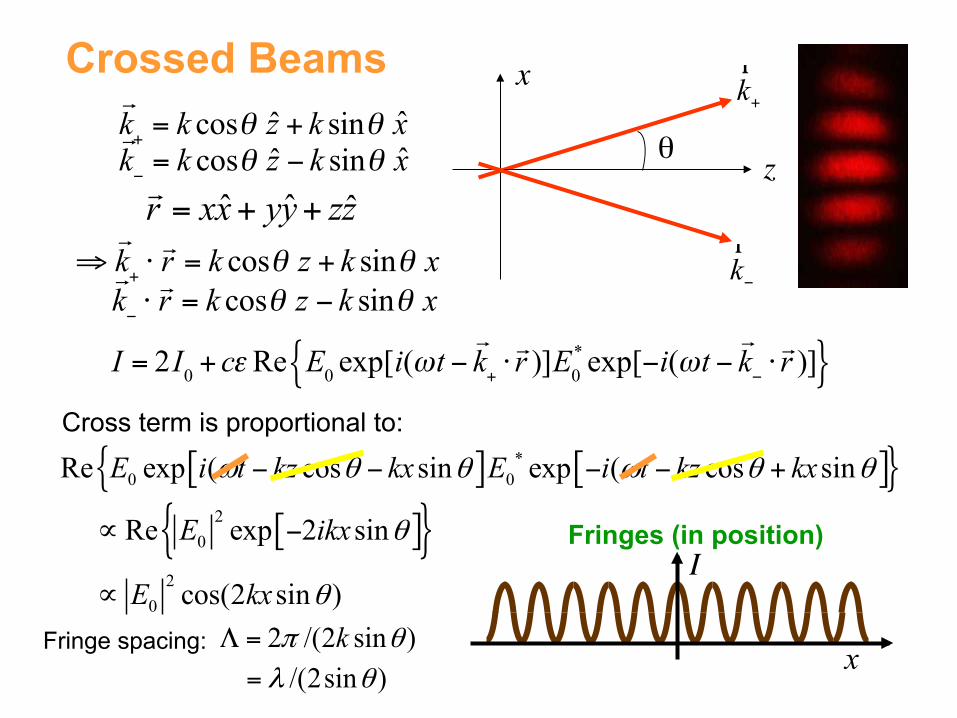
[ ] [ ]{ }[ ]{ }
*0 0
20
20
Re exp ( cos sin exp ( cos sin
Re exp 2 sin
cos(2 sin )
E i t kz kx E i t kz kx
E ikx
E kx
ω θ θ ω θ θ
θ
θ
− − − − +
∝ −
∝
Crossed Beams
θ
k+r
k−r
z
x
!k+ = k cosθ z + k sinθ x
!k− = k cosθ z − k sinθ x
⇒!k+ ⋅!r = k cosθ z + k sinθ x
!k− ⋅!r = k cosθ z − k sinθ x
I = 2I0 + cεRe E0 exp[i(ωt −
!k+ ⋅!r )]E0
* exp[−i(ωt −!k− ⋅!r )]{ }
Cross term is proportional to:
!r = xx+ yy+ zz
2 /(2 sin )kπ θΛ =Fringe spacing: /(2sin )λ θ=
Fringes (in position) I
x
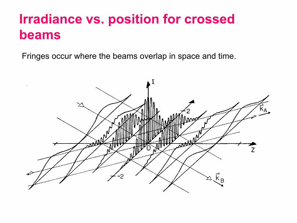
Irradiance vs. position for crossed beams Fringes occur where the beams overlap in space and time.

Big angle: small fringes. Small angle: big fringes.
/(2sin )λ θΛ =
The fringe spacing, Λ:
As the angle decreases to zero, the fringes become larger and larger, until finally, at θ = 0, the intensity pattern becomes constant.
Large angle:
Small angle:

The fringe spacing is: Λ = 0.1 mm is about the minimum fringe spacing you can see:
You can't see the spatial fringes unless the beam angle is very small!
sin /(2 )0.5 / 200
1/ 400 rad 0.15m m
θ θ λ
θ µ µ
≈ = Λ
⇒ ≈
≈ = o
/(2sin )λ θΛ =

The Michelson Interferometer and Spatial Fringes Suppose we misalign the mirrors so the beams cross at an angle when they recombine at the beam splitter. And we won't scan the delay. If the input beam is a plane wave, the cross term becomes: [ ] [ ]{ }
[ ]{ }
*0 0Re exp ( cos sin exp ( cos sin
Re exp 2 sin
cos(2 sin )
E i t kz kx E i t kz kx
ikx
kx
ω θ θ ω θ θ
θ
θ
− − − − +
∝ −
∝
Crossing beams maps delay onto position.
Beam-!splitter!
Input!beam!
Mirror!
Mirror!
z
x
Fringes
Fringes (in position) I
x
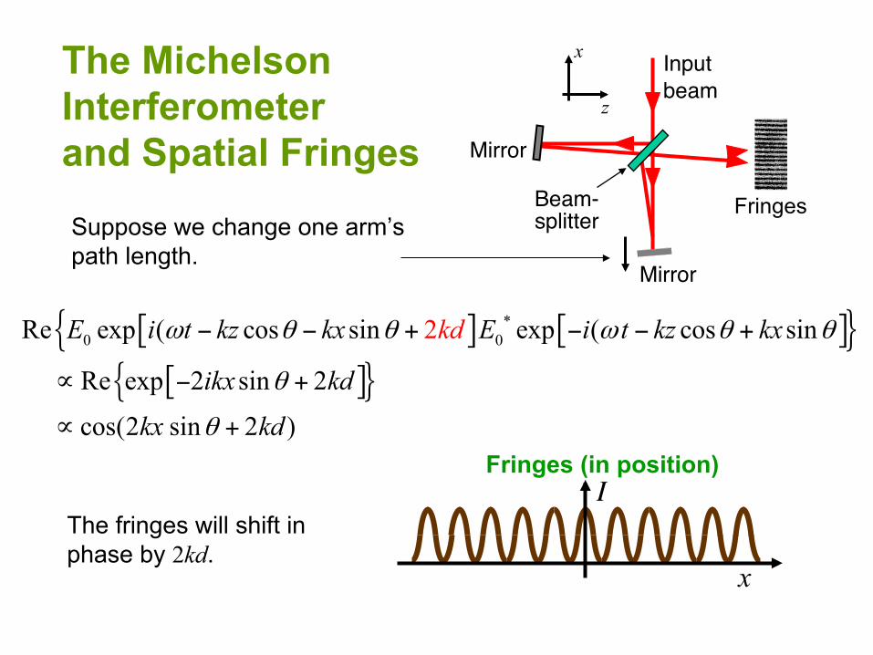
The Michelson Interferometer and Spatial Fringes
Suppose we change one arm’s path length.
[ ] [ ]{ }[ ]{ }
*0 0Re exp ( cos sin exp ( cos sin
Re exp 2 sin 2
cos
2
(2 sin 2 )
E i t kz kx E i t kz kx
ikx kd
kx
k
k
d
d
ω θ θ ω θ θ
θ
θ
− − + − − +
∝ − +
∝ +
The fringes will shift in phase by 2kd.
Beam-!splitter!
Input!beam!
Mirror!
Mirror!
z
x
Fringes
Fringes (in position) I
x

z
The Unbalanced Michelson Interferometer
Now, suppose an object is placed in one arm. In addition to the usual spatial factor, one beam will have a spatially varying phase, exp[2iφ(x,y)]. Now the cross term becomes:
Re{ exp[2iφ(x,y)] exp[-2ikx sinθ] }
Place an object in this path
Misalign mirrors, so beams cross at an angle.
x
Beam-!splitter!
Input!beam!
Mirror!
Mirror!
θ
exp[iφ(x,y)]
Distorted fringes
(in position)
Iout(x)
x

The Unbalanced Michelson Interferometer can sensitively measure phase vs. position.
Phase variations of a small fraction of a wavelength can be measured.
Placing an object in one arm of a misaligned Michelson interferometer will distort the spatial fringes.
Beam-!splitter!
Input!beam!
Mirror!
Mirror!
θ
Spatial fringes distorted by a soldering iron tip in
one path
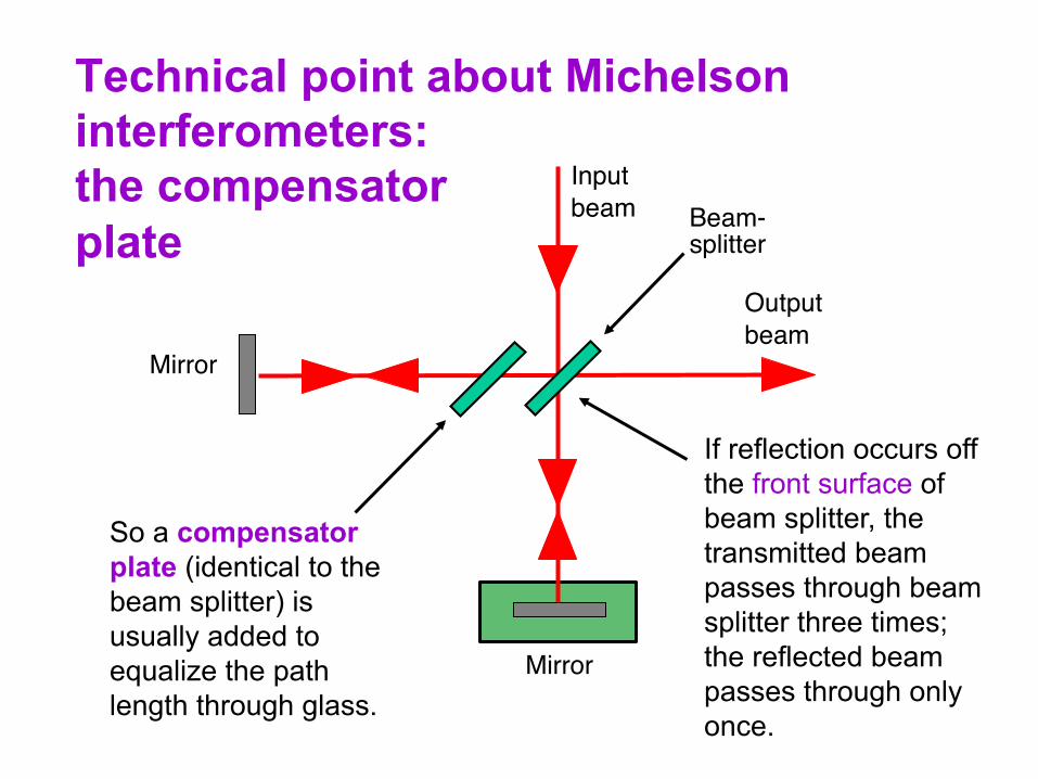
Technical point about Michelson interferometers: the compensator plate Beam-!
splitter!
Input!beam!
Mirror!
Mirror!
Output!beam!
If reflection occurs off the front surface of beam splitter, the transmitted beam passes through beam splitter three times; the reflected beam passes through only once.
So a compensator plate (identical to the beam splitter) is usually added to equalize the path length through glass.
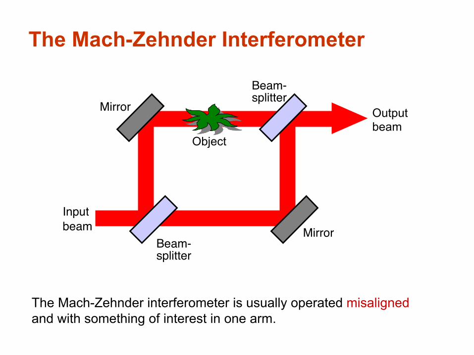
The Mach-Zehnder Interferometer
The Mach-Zehnder interferometer is usually operated misaligned and with something of interest in one arm.
Beam-!splitter!
Input!beam!
Mirror!
Mirror!
Beam-!splitter!
Output beam
Object
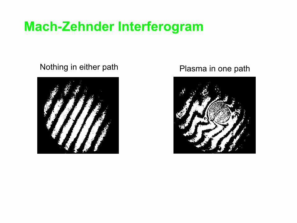
Mach-Zehnder Interferogram
Nothing in either path Plasma in one path
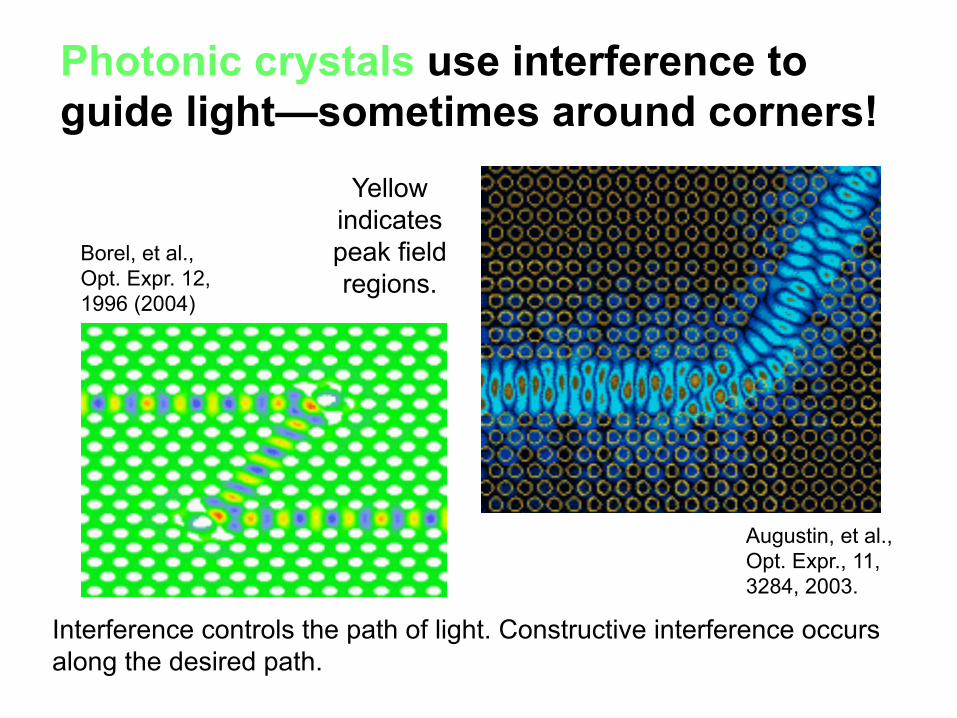
Photonic crystals use interference to guide light—sometimes around corners!
Interference controls the path of light. Constructive interference occurs along the desired path.
Augustin, et al., Opt. Expr., 11, 3284, 2003.
Yellow indicates peak field regions.
Borel, et al., Opt. Expr. 12, 1996 (2004)

Other applications of interferometers
To frequency filter a beam (this is often done inside a laser).
Money is now coated with interferometric inks to help foil counterfeiters. Notice the shade of the “20,” which is shown from two different angles.
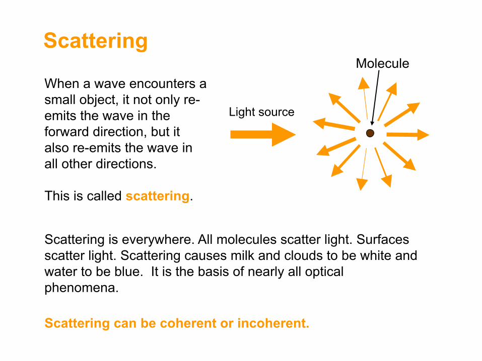
Scattering
When a wave encounters a small object, it not only re-emits the wave in the forward direction, but it also re-emits the wave in all other directions. This is called scattering.
Scattering is everywhere. All molecules scatter light. Surfaces scatter light. Scattering causes milk and clouds to be white and water to be blue. It is the basis of nearly all optical phenomena.
Scattering can be coherent or incoherent.
Light source
Molecule
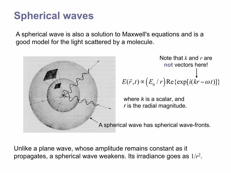
Spherical waves
where k is a scalar, and r is the radial magnitude.
Unlike a plane wave, whose amplitude remains constant as it propagates, a spherical wave weakens. Its irradiance goes as 1/r2.
A spherical wave has spherical wave-fronts.
E(!r ,t)∝ E0 / r( )Re{exp[i(kr −ω t)]}
Note that k and r are not vectors here!
A spherical wave is also a solution to Maxwell's equations and is a good model for the light scattered by a molecule.

Scattered spherical waves often combine to form plane waves. A plane wave impinging on a surface (that is, lots of very small closely spaced scatterers!) will produce a reflected plane wave because all the spherical wavelets interfere constructively along a flat surface.

To determine interference in a given situation, we compute phase delays.
Because the phase is constant along a wave-front, we compute the phase delay from one wave-front to another potential wave-front.
i ik Lφ =
Wave-fronts
L4
L2
L3
L1
Scatterer
Potential wave-front
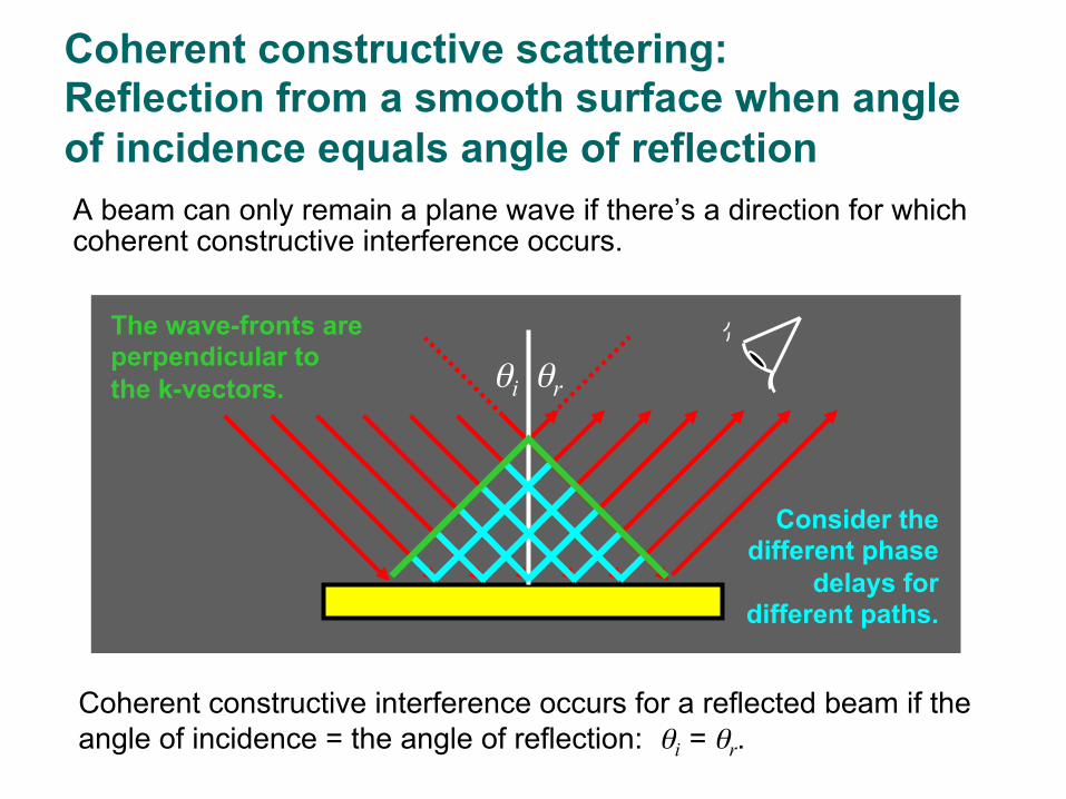
Coherent constructive scattering: Reflection from a smooth surface when angle of incidence equals angle of reflection A beam can only remain a plane wave if there’s a direction for which coherent constructive interference occurs.
Coherent constructive interference occurs for a reflected beam if the angle of incidence = the angle of reflection: θi = θr.
θi θr
The wave-fronts are perpendicular to the k-vectors.
Consider the different phase
delays for different paths.

Coherent destructive scattering: Reflection from a smooth surface when the angle of incidence is not the angle of reflection Imagine that the reflection angle is too big. The symmetry is now gone, and the phases are now all different.
Coherent destructive interference occurs for a reflected beam direction if the angle of incidence ≠ the angle of reflection: θi ≠ θr.
θi θtoo big
Potential wave front a
φ = ka sin(θi) φ = ka sin(θtoo big)
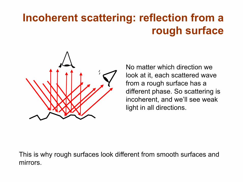
Incoherent scattering: reflection from a rough surface
No matter which direction we look at it, each scattered wave from a rough surface has a different phase. So scattering is incoherent, and we’ll see weak light in all directions.
This is why rough surfaces look different from smooth surfaces and mirrors.