construction of cable route and associated civil works · engineering (signalling) standard...
TRANSCRIPT

© Australian Rail Track Corporation Limited 2009
Disclaimer: This document has been prepared by ARTC for internal use and may not be relied on by any other party without ARTC’s prior written consent. Use
of this document shall be subject to the terms of the relevant contract with ARTC.
ARTC and its employees shall have no liability to unauthorised users of the information for any loss, damage, cost or expense incurred or arising by reason of an unauthorised user using or relying upon the information in this document, whether caused by error, negligence, omission or
misrepresentation in this document.
This document is uncontrolled when printed. Authorised users of this document should visit ARTC’s intranet or extranet (www.artc.com.au) to access the latest version of this document.
Discipline: Engineering (Signalling) Category: Standard
Construction of Cable Route and Associated Civil Works
ESC-11-01
Applicability
ARTC Network Wide CRIA (NSW CRN)
Primary Source
SC 09 01
Document Status
Version Date Reviewed Prepared by Reviewed by Endorsed Approved
1.2 13 August 2010 Standards Stakeholders Chief Operating Officer
Risk & Safety Committee 09/06/2009
Amendment Record
Version Date Reviewed Clause Description of Amendment
1.0 15 Jun 09 First issue. Supersedes Common Standard SC 09 01 v1.1 and in part NSW Standard SCP 21 v1.2. Includes minor changes to SC 09 01 v1.1 as approved by Exec Manager Stds, Sys & Performance on 07/07/2009 as reported to Risk & Safety Committee 14/09/2009.
1.1 07 Oct 09 Disclaimer updated as per Risk & Safety Committee 14/09/2009. References to Common Signalling Construction Standard numbers updated to new numbering scheme.
1.2 13 August 2010 All Issued as final.

Engineering (Signalling) Standard ESC-11-01 Construction of Cable Route and Associated Civil Works Contents
Contents
1 General ................................................................................................... 7 1.1 Scope.............................................................................................. 7 1.2 Safety ............................................................................................. 7 1.3 Occupational Health and Safety........................................................... 7 1.4 Drawings ......................................................................................... 7 1.5 Definitions ....................................................................................... 7 1.6 Quality ............................................................................................ 8 1.7 Submissions for Approval ................................................................... 8 1.8 Referenced Documents ...................................................................... 8
1.8.1 Australian Standards................................................................ 8 1.8.2 ARTC Standards ...................................................................... 9 1.8.3 Drawings ............................................................................... 9
1.9 Special Conditions............................................................................. 9 1.10 Environmental Considerations............................................................. 9 1.11 Submissions for Approval ................................................................... 9 1.12 Responsibilities ................................................................................. 9 1.13 Site Surveys................................................................................... 10 1.14 Location of Equipment ..................................................................... 10 1.15 Signal Location ............................................................................... 10 1.16 Installation Drawings....................................................................... 10 1.17 Existing Equipment ......................................................................... 10 1.18 Temporary Level Crossings............................................................... 11 1.19 Location of Existing Services/Cabling ................................................. 11
2 Supply of Materials ............................................................................... 11 2.1 Material Supplied by ARTC................................................................ 11 2.2 Material Supplied by the Contractor ................................................... 11 2.3 Painting/Finish of Metal Surfaces ....................................................... 12
3 Excavation, Boring, Backfilling And Compaction ................................... 12 3.1 Excavation ..................................................................................... 12
3.1.1 Location of Existing Services ................................................... 12 3.1.2 Preparation of Cable Route ..................................................... 12 3.1.3 Stability of Excavation............................................................ 13 3.1.4 Placement of Spoil................................................................. 13 3.1.5 Programming of work............................................................. 13 3.1.6 Public Safety ........................................................................ 13
Version 1.2 Date of last revision: 13 August 2010 Page 2 of 55 This document is uncontrolled when printed. See ARTC Intranet for latest version.

Engineering (Signalling) Standard ESC-11-01 Construction of Cable Route and Associated Civil Works Contents
3.1.7 Proximity to Existing Services ................................................. 13 3.2 Inspection before Backfilling ............................................................. 14 3.3 Backfilling ...................................................................................... 14 3.4 Compaction.................................................................................... 14
4 Concrete and Stabilised Sand................................................................ 15 4.1 General ......................................................................................... 15 4.2 Ready Mix Concrete and Stabilised Sand ............................................ 15 4.3 Site Mixed Concrete and Stabilised Sand ............................................ 15 4.4 Concrete Reinforcing ....................................................................... 15 4.5 Concrete Finish............................................................................... 15
5 Cable Route General Requirements....................................................... 16 5.1 General ......................................................................................... 16 5.2 Location of the Cable Route .............................................................. 16 5.3 Types of Cable Route....................................................................... 16 5.4 Radius of Bends.............................................................................. 17 5.5 Underline Crossing (ULX) and Under Road Crossings (URX)................... 17 5.6 Cable Pits ...................................................................................... 17
6 Buried Cable Route ............................................................................... 17 6.1 General ......................................................................................... 17 6.2 Depth of Cable Route....................................................................... 17 6.3 Shared Trenches............................................................................. 17 6.4 Protective Cover over Signalling and Communications Cables ................ 17 6.5 PVC Cable Marker Tape in Trenches ................................................... 18 6.6 Rock Areas..................................................................................... 18 6.7 Cable and Pipe Ploughing – Preparation of Route ................................. 18 6.8 Cable Ploughing – General................................................................ 18 6.9 Cable Ploughing - Demonstration ...................................................... 19 6.10 Cable Ploughing – Restoration........................................................... 19 6.11 Buried Pipes ................................................................................... 19 6.12 Spare Buried Pipes .......................................................................... 20 6.13 Pipes in Platforms and Other Paved Areas........................................... 20 6.14 Buried Cables through Water Courses ................................................ 20 6.15 Cable Routes on Embankments ......................................................... 20 6.16 Underground Services of Other Authorities ......................................... 21 6.17 Special Earthing Arrangements ......................................................... 21 6.18 Cable Route Markers ....................................................................... 21
7 Ground Level Troughing (GLT) Cable Route .......................................... 21
Version 1.2 Date of last revision: 13 August 2010 Page 3 of 55 This document is uncontrolled when printed. See ARTC Intranet for latest version.

Engineering (Signalling) Standard ESC-11-01 Construction of Cable Route and Associated Civil Works Contents
7.1 General ......................................................................................... 21 7.2 Troughing Route Capacity ................................................................ 22 7.3 Installation of GLT........................................................................... 22 7.4 Drainage........................................................................................ 22 7.5 Lids............................................................................................... 22
8 Galvanised Steel Troughing (GST) Cable Route .................................... 22 8.1 General ......................................................................................... 22 8.2 Troughing Route Capacity ................................................................ 23 8.3 Bends............................................................................................ 23 8.4 Expansion Joints and Insulated Sections............................................. 23 8.5 Mounting Brackets and Fittings ......................................................... 24 8.6 Troughing on Posts.......................................................................... 24 8.7 Troughing on Railway Bridges or Viaducts........................................... 24 8.8 Troughing on Rock Faces ................................................................. 24 8.9 Troughing on Walls ......................................................................... 25 8.10 Troughing in Tunnels or through Underbridges with Limited Clearances .. 25 8.11 Troughing across Culverts etc ........................................................... 25 8.12 Transition between GST/GLT/Buried Cable Route................................. 25 8.13 Troughing Arrangements at Entries to Location Cases .......................... 25 8.14 Fitting of Lids ................................................................................. 26
9 Cable Ladder Cable Route ..................................................................... 26 9.1 General ......................................................................................... 26 9.2 Cable Ladder Environment................................................................ 26 9.3 Cable Ladder Capacity ..................................................................... 26 9.4 Bends............................................................................................ 26 9.5 Joints, Expansion Joints and Insulation Gaps....................................... 27 9.6 Mounting Brackets and Fittings ......................................................... 27 9.7 Cable Ladder in Tunnels or Through Under-bridges .............................. 27 9.8 Transition between Cable Ladder / Cable Ladder / GST / GLT / Buried Route
.................................................................................................... 27 9.9 Cable Ladder & Connection to Local Cable Route/Equipment.................. 28 9.10 Cable Installation ............................................................................ 28 9.11 Cable Ladder Covers........................................................................ 28
10 Pipe Cable Route................................................................................... 28
11 Underline and Under-Road Crossings (ULX and URX) ........................... 29 11.1 General ......................................................................................... 29 11.2 Depth of ULX/URX........................................................................... 29
Version 1.2 Date of last revision: 13 August 2010 Page 4 of 55 This document is uncontrolled when printed. See ARTC Intranet for latest version.

Engineering (Signalling) Standard ESC-11-01 Construction of Cable Route and Associated Civil Works Contents
11.3 ULX or URX by Trenching ................................................................. 29 11.4 Underline Crossings (ULX)................................................................ 30 11.5 Under road Crossings (URX) ............................................................. 30
12 Cable Pits, Cable Jointing Pits and Cable Turning Chambers................. 30 12.1 General ......................................................................................... 30 12.2 Location of Cable Pits ...................................................................... 30 12.3 Location of Cable Jointing Pits........................................................... 31 12.4 Location of Cable Turning Chambers .................................................. 31 12.5 Construction of Cable Pits, Cable Jointing Pits and Cable Turning Chambers
.................................................................................................... 31 12.6 Erosion of Embankments.................................................................. 32 12.7 Covers........................................................................................... 32
13 Cable Installation ................................................................................. 33 13.1 General ......................................................................................... 33
13.1.1 Communications ................................................................... 33 13.1.2 Protection of Cables............................................................... 33 13.1.3 Order of Laying..................................................................... 33 13.1.4 Separation ........................................................................... 33 13.1.5 Bonding Cables ..................................................................... 33 13.1.6 Length of Cables ................................................................... 34 13.1.7 Cable Joints.......................................................................... 34
13.2 Protection of Cables During Installation .............................................. 34 13.3 Cable Marking ................................................................................ 35 13.4 Sealing of Cable Entries ................................................................... 35
14 Testing of Cables .................................................................................. 35 14.1 General ......................................................................................... 35 14.2 Test Records .................................................................................. 35
15 Construction of Railway Access Road.................................................... 35 15.1 General ......................................................................................... 35 15.2 Cable Route Intersection with Access Roads........................................ 35 15.3 Construction................................................................................... 36
16 Fencing, Gates and Retaining Walls ...................................................... 36 16.1 Fencing and Gates .......................................................................... 36 16.2 Modifications to Existing Fencing ....................................................... 36 16.3 Temporary Fences........................................................................... 36 16.4 Bollards ......................................................................................... 37
17 Retaining Walls..................................................................................... 37
Version 1.2 Date of last revision: 13 August 2010 Page 5 of 55 This document is uncontrolled when printed. See ARTC Intranet for latest version.

Engineering (Signalling) Standard ESC-11-01 Construction of Cable Route and Associated Civil Works Contents
17.1 General ......................................................................................... 37
18 Removal of Redundant Material, Equipment and Surplus Spoil ............. 37 18.1 General ......................................................................................... 37 18.2 Time Limit ..................................................................................... 37 18.3 Reclaimable Equipment.................................................................... 38 18.4 Equipment and Materials to be Removed ............................................ 38
19 Site Survey Drawings............................................................................ 38
20 Appendix A: Cable Search Form ESC1101F-01 (example only) ............. 40
21 Appendix B: ULX Inspection Report ESC1101F-02 (example only) ....... 41
22 Appendix C: Drawings........................................................................... 42
23 Particular Standard References ............................................................ 55
Version 1.2 Date of last revision: 13 August 2010 Page 6 of 55 This document is uncontrolled when printed. See ARTC Intranet for latest version.

Engineering (Signalling) Standard ESC-11-01 Construction of Cable Route and Associated Civil Works General
1 General
1.1 Scope This document describes the requirements for the following works:
• Construction of cable routes.
• Construction of under line (ULX) and under road (URX) crossings.
• Construction of cable pits, jointing pits and cable turning chambers.
• Installation of all main and local signalling, communications and power cables.
• Construction of access roads and associated works.
• Removal of redundant material, equipment and surplus spoil.
Except as otherwise noted in the Particular Standard, all items of equipment and all materials required for installation shall be supplied and installed by the Contractor as part of any Contract.
This Standard shall be read in conjunction with all other relevant Signalling Standards referenced within this document and the Particular Standard.
1.2 Safety The Contractor shall at all times arrange for the work to be carried out in a manner which will ensure the safety of employees, not cause danger, delay, obstruction or stoppage to railway traffic and not interfere with the business of ARTC or its Operators.
The Contractor shall ensure that all staff working on the Contract including sub-contractors staff is appropriately accredited for work on or about Rail corridors in accordance with ARTC network Operations and Safeworking requirements.
1.3 Occupational Health and Safety The Contractors and sub-contractors, if any, shall comply with the relevant safety legislation of the Occupational Health and Safety Act.
1.4 Drawings The documentation and drawings to be used in the execution of the works shall be the relevant approved Contractors drawings plus any other drawings nominated in the Particular Standard.
1.5 Definitions The following definitions apply in this Standard. The terminology may not necessary have the same meaning in other Standards or in referenced documents. In this document, the following definitions of terms shall apply:
Term or acronym Description
ARTC Australian Rail Track Corporation
Contractor A person, company or authority nominated by ARTC or ARTC’s primary contractor to manage a specific contract.
ARTC’s Representative A person, company or authority nominated by ARTC to make engineering determinations on ARTC’s behalf.
External cable route External cable route is any cable route not in a building.
Internal cable route Internal cable route means any cable route inside a building.
Location case (also called location Location cases are signalling equipment cupboards or housings
Version 1.2 Date of last revision: 13 August 2010 Page 7 of 55 This document is uncontrolled when printed. See ARTC Intranet for latest version.

Engineering (Signalling) Standard ESC-11-01 Construction of Cable Route and Associated Civil Works General
cupboards or locations) that are not buildings.
Local cable route (also called local route)
Local cable route is any cable route that does not fall into the category of main or internal cable route.
Local cables Local cables are all cables not being main cables.
Low voltage For the purposes of this Standard low voltage is 120 volts (nominal) or less.
Main cable route (also called main route)
Main cable route means any external cable route that contains or is intended to contain at least one main cable.
Main cables Main cables are any cables that are run from a cable termination point in one building, equipment room or location case to a cable termination point in another building, equipment room or location case. Note that joints in cables including those for loading and balancing purposes do not constitute a termination of the cable for the purposes of defining main cables.
Stabilised sand Stabilised sand is a mixture of sand and Portland cement in the ration 10:1.
1.6 Quality
The standard of materials and workmanship shall ensure that the installed system is fit for purpose, over the lifetime of the asset in its physical and operational environment, in terms of safety and reliability.
All materials and equipment shall be manufactured and assembled to provide a minimum service life of 20 years when maintained and/or overhauled at the manufacturer’s recommended intervals.
Quality of materials and workmanship shall be such that life cycle routine maintenance of the asset is minimised.
All materials and equipment supplied to this Standard shall be warranted free of defect in manufacture or assembly for a period of twenty four (24) months from delivery.
All of the materials and equipment, including consumables, shall be warranted as complying with this or any referenced Standard and as being fit for purpose.
1.7 Submissions for Approval Where alternatives or new equipment types are proposed, the matter shall be submitted by the Contractor with documented justification in writing, in accordance with ARTC’s PP-122 acceptance process for “New Equipment and Systems” approval.
1.8 Referenced Documents The following documents are referenced in this Standard:
1.8.1 Australian Standards
The following documents and drawings are referenced in this Standard:
AS 1304 / AS 1302 Reinforcing Mesh
AS 1289 Methods of Testing Soils for Engineering Purposes
AS 1379 Manufacture of concrete
AS 1650 Hot dipped galvanised coatings
AS 1657 Fixed platforms, walkways, ladders, stairways
AS 2758.1 Aggregates for concrete
AS 3679.1 Hot rolled bars and sections
AS 3972 Portland and blended cements
Version 1.2 Date of last revision: 13 August 2010 Page 8 of 55 This document is uncontrolled when printed. See ARTC Intranet for latest version.

Engineering (Signalling) Standard ESC-11-01 Construction of Cable Route and Associated Civil Works General
AS 1725 Galvanised Chain wire security Fencing & Gates
Austel Premises Manual Communications Volumes 1 & 2
1.8.2 ARTC Standards
ESC-07-04 Install of Equipment Racks and Termination of Cables and Wiring
ESC-03-01 Level Crossing Equipment
ESC-07-03 Small Buildings, Location Cases, Terminal Cases and General Purpose Cases
ESC-09-02 Lightning and Surge Protection Requirements
ESC-07-01 Installation of Trackside Equipment
ESA 11 01 Cables for Railway Signalling Applications – General Requirements
1.8.3 Drawings
Refer to Appendix C.
1.9 Special Conditions When working in the vicinity off or adjacent to overhead electrified areas Special Conditions shall apply.
1.10 Environmental Considerations The Contractor is not exempt from statutory obligations and shall conform to all of the appropriate Local Government, Environmental Protection Acts and subordinate regulations applicable within the construction site jurisdiction.
All cable route/s shall be designed to be as unobtrusive as possible, both to reduce its visual impact on its surroundings and to avoid drawing attention to the presence of copper cable.
The route shall not be attached to or alter the appearance of any building or structure which is on a heritage list or is subject to a preservation order without specific approval from the relevant heritage authorities.
Trees or shrubs shall only be removed or lopped to the least extent necessary for construction of the route. Care shall be taken not to damage the root systems of mature or substantial trees.
During the construction of trenching for buried cable route or ground level ducting, care shall be taken to prevent silt runoff into any waterway and to prevent blockage of any natural or track drainage.
1.11 Submissions for Approval Where alternatives are proposed, the matter shall be submitted by the Contractor, with documented justification in writing, in accordance with ARTC’s acceptance process for “New Systems or Equipment”.
1.12 Responsibilities Unless otherwise specifically stated herein or in the Particular Standard, all work and actions specified or implied in this Standard and the supply of all material and plant necessary to carry out the work shall be the responsibility of the Contractor.
Version 1.2 Date of last revision: 13 August 2010 Page 9 of 55 This document is uncontrolled when printed. See ARTC Intranet for latest version.

Engineering (Signalling) Standard ESC-11-01 Construction of Cable Route and Associated Civil Works General
1.13 Site Surveys Site surveys shall be carried out to determine locations for external work including equipment, structures, buildings, equipment housings, track circuit limits, foundations, cable routes, under-track crossings and all like work.
Site survey drawings, installation drawings and notes etc. shall be prepared and submitted to ARTC’s representative for acceptance at least 14 days prior to work commencing.
Site works shall be executed in accordance with the accepted site survey drawings, installation drawings and notes etc.
These site survey drawings shall show the information requirements in respect to cables routes as detailed in Section 19.
The final AS-Built Site Survey Drawings shall reflect the requirements of Section 19. and include the installed cable route arrangements.
1.14 Location of Equipment No equipment shall be located within the Standard Structure Gauge envelope.
If site constraints are such that the equipment cannot be installed without infringement of this envelope, details of the required infringement shall be referred to ARTC in accordance with section 1.11 above.
1.15 Signal Location During the site survey, the actual positions for the installation of signals in accordance with the requirements laid down in the relevant sections of Standard ESC-07-01 Installation of Trackside Equipment, shall be established.
Signal positioning will be conducted by the Signal Sighting Group in accordance with ESC-04-01 Signal Sighting and Position.
Each signal shall be positioned in relation to rail level, the structure gauge and shall be given a kilometrage or a distance from a well defined structure such as a bridge, platform or gantry.
The distance from the running face of the nearest rail to the centre of a signal of standard width shall normally be 2.5 metres. Where the signals cannot be located adjacent to the track in the correct position due to the closeness of adjacent tracks or some other obstruction, the requirements of Standard ESC-07-01 Installation of Trackside Equipment, shall apply.
When the positions for signals, indicator signals, guards indicators etc., have been determined by the Signal Sighting Group, master copies of signal sighting forms with full details and information, duly completed to ARTC’s current practice shall be compiled and retained for future referencing.
These Signal sighting forms appropriately endorsed by all parties shall then be used in conjunction with the Signalling Plans and site survey details for the execution of the Works.
1.16 Installation Drawings This Standard includes, or references, a number of standard installation drawings illustrating guidelines for the construction of cable route.
Where standard installation drawings are not supplied or where particular problems are encountered on site that require special arrangements or equipment to complete the work, the necessary construction/installation drawings shall be prepared and submitted in accordance with Section 1.11 above.
1.17 Existing Equipment Where existing signalling or communications equipment, that is ultimately to be removed or recovered, inhibits the installation of new signalling or communications equipment, ARTC’s Representative will determine the action to be taken. The Contractor may be directed to:
Version 1.2 Date of last revision: 13 August 2010 Page 10 of 55 This document is uncontrolled when printed. See ARTC Intranet for latest version.

Engineering (Signalling) Standard ESC-11-01 Construction of Cable Route and Associated Civil Works Supply of Materials
• Carry out temporary work.
• Re-position the new equipment.
1.18 Temporary Level Crossings Temporary level crossings shall not be constructed without prior written approval.
Temporary level crossings shall comply with ARTC’s procedures for construction, level of protection and operation of temporary level crossings.
The Contractor shall be responsible for the cost of construction of the temporary level crossings, and for their maintenance and operation including the provision of protection as required.
At the completion of the work these level crossings shall be removed and the track restored to a condition at least equal to that of the track on either side of the crossing.
1.19 Location of Existing Services/Cabling The construction area is likely to contain numerous existing buried utility services e.g. water, gas, electricity, communications etc, not all of which are fully documented.
The location of all utility services and existing ARTC cabling within a one metre distance of any proposed installation work shall be determined by the Contractor prior to commencing the work.
In the case of existing ARTC cabling, the Cable Search form (ESC1101F-01) contained in Appendix A shall be used.
Where utility services are involved, the search requirements relevant to each of the utility service providers shall be used.
2 Supply of Materials
2.1 Material Supplied by ARTC If it is agreed that ARTC will supply cables or other materials for the works, either in full or part, the material will be made available at an agreed location (or locations) for collection.
After collection responsibility for the safe storage and handling of such equipment or materials, effective and efficient use of the quantities supplied and maintenance of quality records (including serial numbers, reference number etc) and installation records rests solely with the Contractor.
Accurate records shall be maintained on the cables or other materials supplied, the quantities installed and the locations where they have been installed. A copy of these records shall be available to ARTC’S Representative on demand and when requests are submitted for further supplies of cables or other materials.
Unused cables and other materials shall be delivered, unloaded and stockpiled at a nominated site within a 20km radius of the worksite.
2.2 Material Supplied by the Contractor All materials and equipment used in the works shall be covered by the quality and test and inspection documentation required by ESA-11-01 Cables for Railway Signalling Applications – General Requirements.
In particular, cable drums shall be supplied with drum numbers marked on the drum and the cable manufacturer’s factory test results sheets.
Cable drums with illegible or no drum numbers shall be rejected.
Any drums missing manufacturer’s test data sheets shall not be used.
Version 1.2 Date of last revision: 13 August 2010 Page 11 of 55 This document is uncontrolled when printed. See ARTC Intranet for latest version.

Engineering (Signalling) Standard ESC-11-01 Construction of Cable Route and Associated Civil Works Excavation, Boring, Backfilling And Compaction
2.3 Painting/Finish of Metal Surfaces All steel components or constructions shall be proofed against corrosion by a process that will provide a minimum service life of 20 years in the environment in which the components or constructions are installed.
In selecting the process to be used, the likelihood of minor damage during installation such as scrapping, scratching and chipping shall be taken into account.
Painted or powder coated finishes are not acceptable as the primary corrosion proofing process in external applications, they may only be used to provide additional protection in those instances or locations where the primary process cannot provide the specified service life.
Fasteners used externally to buildings shall either be plated or of a material which will provide the specified life. (Note: If stainless steel nuts are used on stainless steel fasteners, an anti-seize product shall be used between nut and bolt).
For applications within buildings, except in wet areas such as cable pits, the level of protection may be reduced to zinc plating or equivalent.
Painting of galvanised (or equivalently plated) steel, stainless, steel and aluminium metalwork is not necessary except where required for additional protection or where it is called for in the Particular Standard.
Where a paint finish is specified, powder coating, enamel, epoxy coatings or acrylic lacquer finishes may be used. The metal surfaces shall be prepared, undercoated and finished in accordance with the paint manufacturer’s recommendations.
Finish colour of painted surfaces shall be compatible with the environment in which they are located.
3 Excavation, Boring, Backfilling And Compaction
3.1 Excavation
3.1.1 Location of Existing Services
Before excavation or boring operations commence, the location of all existing signalling and communications cables, railway drains and all other underground services in the area to be excavated including water, stormwater, sewerage, gas, power and telephone cables shall be located and marked.
The use of mechanical digging or boring machines for excavation within 2 metres of high voltage cables or within 1 metre of other existing underground service is not permitted. Excavation within 2 metres of high voltage cables or within 1 metre of other existing underground services shall be performed using hand tools.
Explosives shall not be used in the performance of the work under the Contract.
3.1.2 Preparation of Cable Route
The selected cable route shall be cleared and levelled only to the extent necessary to permit trenching and access for plant/vehicles. Any debris, excess soil and/or rock shall be disposed to a rubbish tip or other suitable location. Any railway materials (eg sleepers) in the cable route path shall be relocated to a suitably agreed location.
Care shall be taken to ensure that this work does not block natural drains or create un-drained areas.
Excavations shall be to the minimum width and depth necessary to best carry out the work in accordance with this Standard. The bottom of trenches shall be level and even, free from stones, sharp objects etc.
Version 1.2 Date of last revision: 13 August 2010 Page 12 of 55 This document is uncontrolled when printed. See ARTC Intranet for latest version.

Engineering (Signalling) Standard ESC-11-01 Construction of Cable Route and Associated Civil Works Excavation, Boring, Backfilling And Compaction
3.1.3 Stability of Excavation
Excavations in or near tracks, platforms or access roads shall be securely shored to prevent the sides of the excavation from collapsing. All trenches shall be shored to comply with the requirements of the Construction Safety Act.
Excavation work shall not commence in or near tracks, platforms or access roads until sufficient shoring material is available on site to shore up the excavations as the work progresses.
3.1.4 Placement of Spoil
Spoil shall not be placed on ballast or foul of track gauge or access-ways. If spoil has to be temporarily placed on the track, tarpaulins, plywood or other suitable material shall be used to provide a barrier between the ballast and the spoil.
Spoil placed between the rails or within 1000mm from any rail shall not extend above the top of rail level.
Spoil shall not be placed in a position where it could obstruct track drainage or be washed into track drains or onto the ballast during periods of heavy rain.
Spoil shall not be placed in a position where it may damage or affect the operation of existing equipment (eg. Mechanical signalling control rodding or wires, cable routes, power operated points etc.).
3.1.5 Programming of work
As far as possible trenching, cable laying and backfilling shall be carried out progressively and concurrently so that trenches are open for the minimum possible time. Work shall be planned such that trenches are required to be kept open for a maximum of five working days. The exception to this requirement being:
• Trenches under or within 3 metres of operating tracks, or
• where the stability of the embankment and or formation is affected, or
• through sidings.
In these situations, the trench shall not be kept open overnight unless it is shored to prevent any movement of surrounding ground under any weather conditions.
Drivers safe & unrestricted access to signal telephones shall be maintained at all times.
3.1.6 Public Safety
To ensure the safety of the general Public and railway infrastructure workers, suitable barricades shall be erected around excavations, or covers provided across excavations where continuous access is required across them, when work is not actually taking place. Barricades shall have a minimum height of 1000mm and barricades and covers shall comply with the Occupational Health and Safety Act.
Excavation on platforms shall cause the minimum interference and risk to the public and train operators. Temporary covers shall be provided for trenches to allow access to trains, platform amenities and booking offices. At no time while train services are running shall access to or from the platform to any part of a train be blocked.
Excavated material shall not be stockpiled on platforms unless agreement is reached with the Railway station owner.
3.1.7 Proximity to Existing Services
When trenching alongside or across gas, water mains or service utility lines the Contractor shall comply with any restrictions which may apply to the easement and liaise with the owners of that easement and Service owners to establish mutually agreed methods of protection and support for the services.
Version 1.2 Date of last revision: 13 August 2010 Page 13 of 55 This document is uncontrolled when printed. See ARTC Intranet for latest version.

Engineering (Signalling) Standard ESC-11-01 Construction of Cable Route and Associated Civil Works Excavation, Boring, Backfilling And Compaction
Excavation within 500mm of existing services shall not be permitted until the service is carefully exposed and protected with 12mm steel plate or other suitable material.
On completion of the work the service shall be jointly inspected by the service owner and the Contractor to ensure that no damage has occurred and that the service is operating correctly.
3.2 Inspection before Backfilling Trenches and other excavations shall not be backfilled until inspected by the Contractors Site Supervisor and appropriately signed off. A record of these inspections is to be placed on the site installation documentation.
3.3 Backfilling Pipes and cables shall be encased in clean fill to 50 mm above the uppermost pipe or cable.
Whenever excavation of the track formation occurs the formation shall be restored with compacted 20mm fine crushed rock to the top of the capping layer. Any geotechnical fabric encountered during excavation shall be replaced with like material, which overlaps the original, by at least 300 mm.
Ballast shall not be replaced until the trench or excavation has been filled and compacted level with the top of the capping layer.
Where the buried pipe or cable is located in areas other than track formation, platforms, access roads or pathways, the trench above the clean fill shall be filled with material free of broken concrete, brick, rubble, wood, glass, rubbish, steel or other metallic objects which could damage the cable or effect the operation of electronic cable locators and shall have no particles greater than 50mm.
As a minimum, the top 300mm of fill in access roads or pathways which are not sealed shall consist of material which as closely as possible matches that in the road or pathway surface in both texture and density. The fill shall be compacted as necessary to achieve matching density. Where the road or path is sealed, the trench shall be capped with the same material to the same thickness as the original seal. Any substrate or capping layer below the seal shall also be matched.
Surface drains shall be reinstated during the backfilling operations.
The backfilling of the excavations will normally take up the majority of the spoil. However, any surplus spoil or unsuitable fill shall be removed for disposal at an appropriate location.
Prior to the issue of the Handover Certificate, all backfilled trenches and excavations shall be examined and any depressions caused by settlement or erosion of the backfilling shall be corrected and the cause rectified.
3.4 Compaction The first 150 mm of fill over cover strips or pipes shall be carefully compacted to ensure that the cover strips / pipes are not disturbed.
Trenches and other excavations in the track formation, platforms, roads, and pathways, through shunting yards or at the base of embankments shall be:
• Compacted in layers by mechanical means to achieve 98% Standard Compaction in accordance with AS1289, and
• Filled and compacted in layers of 150 mm maximum thickness to achieve the specified density.
Tests shall be performed by the Contractor using a NATA approved laboratory to establish the backfill compaction levels achieved. These tests shall be representative of the full depth of the trench.
Where backfill does not achieve the required density, it shall be re-excavated to within 200 mm of the cover strips and/or pipes and re-filled and compacted correctly.
Version 1.2 Date of last revision: 13 August 2010 Page 14 of 55 This document is uncontrolled when printed. See ARTC Intranet for latest version.
Engineering (Signalling) Standard ESC-11-01 Construction of Cable Route and Associated Civil Works Concrete and Stabilised Sand
Trenches and excavations in other areas, not specified above, may be compacted by any convenient means, e.g. by using the wheels of a backhoe or bobcat. Following compaction, the trench or excavation shall be finished with a slight mound, height equal to approximately 20% of trench width, to provide for further settlement.
4 Concrete and Stabilised Sand
4.1 General This section of the Standard details the requirements for the supply of:
• concrete for the construction of foundations, footpaths, cable pits and other concrete structures of a minor nature.
• stabilised sand.
Except when otherwise approved, ready mixed concrete shall be used in the construction of all concrete structures.
4.2 Ready Mix Concrete and Stabilised Sand Ready mixed concrete and stabilised sand shall be produced in accordance with the requirements of AS1379. The Contractor shall be responsible for ensuring that concrete and stabilised sand is ordered with the correct properties for its intended application.
Concrete strength at 28 days shall be not less than 20 Mpa.
Concrete additives shall not be used without approval.
4.3 Site Mixed Concrete and Stabilised Sand The materials for site mixed concrete and stabilised sand shall be kept free of foreign matters at all times.
Concrete mix portions by volume shall be as necessary to obtain the necessary strength for the particular application with a minimum strength of 20 Mpa for any application.
Portland cement type A to AS3972 shall be used unless otherwise specified and aggregate shall comply with AS2758.1.
Mixing water shall be clean and free from substances deleterious to concrete or steel.
Chemical admixtures or fly ash shall not be used in the concrete mix.
4.4 Concrete Reinforcing All concrete structures and pathways shall be appropriately reinforced with welded rust free steel mesh to AS1304 and/or steel bar to AS1302 of sufficient cross-sectional area for the calculated loadings.
Reinforcement shall be placed and tied (and/or welded) in accordance with the Contractors design drawings.
4.5 Concrete Finish Internal concrete surfaces shall be free of voids and steel trowelled to a smooth finish. External concrete surfaces shall be finished to a non-slip wood trowelled finish.
Concrete edges and corners shall be chamfered to minimise chipping and breaking.
Concrete surfaces shall be level except where a slope is required to form a ramp or to disperse water away from a building or other structure.
Version 1.2 Date of last revision: 13 August 2010 Page 15 of 55 This document is uncontrolled when printed. See ARTC Intranet for latest version.

Engineering (Signalling) Standard ESC-11-01 Construction of Cable Route and Associated Civil Works Cable Route General Requirements
5 Cable Route General Requirements
5.1 General The setting out and the construction of the cable route shall be in accordance with the provisions of this Standard, and Austel Premises Manual Volume 1 & 2.
Except as otherwise specified, the main cable route shall be installed on one side of the track (except where there are four tracks or more, in which case the route may be split to run down each side when convenient) and shall cross the track the least possible number of times.
Local cable routes shall be installed as required.
Cable routes shall, so far as possible, follow a constant grade and line.
Rough and uneven ground shall be levelled to the extent necessary to achieve this objective. Where buried route is installed, only sufficient surface levelling to provide access shall be carried out. Levelling work shall not adversely affect railway or natural drainage, or pedestrian or vehicular access routes.
5.2 Location of the Cable Route Generally the cable route shall be located as near as possible to the railway boundary. The preferred locations for cable routes are shown on Drawing Nos. SC 09 01/01, SC 09 01/02 and SC 09 01/03.
The minimum distance from the running face of the nearest rail to the cable route shall be not less than four (4) metres unless otherwise agreed.
Cable routes shall be parallel to the running lines wherever possible.
The cable route shall be located and installed so that it does not divert or interfere with any drainage (railway or natural) or underground services. Special care shall be taken to ensure that the route will not affect the stability of any embankment or cutting.
Where large waterways, gullies or roadways under tracks are encountered the cable route may be fixed to available bridge structure using approved attachments as set out in Section 8.
For small creeks and occasional waterways the cables shall be enclosed in pipes laid in trenches under the creek bed as set out in Section 6.
Cable routes shall, where possible, be on the side of the tracks not occupied by high voltage earthed locations such as sub-stations, power sectioning huts and transformer locations.
Cable routes under roadways shall be installed within the railway corridor boundary whenever possible.
Where the cable route cannot be located within the railway corridor, all negotiations with the owners of land affected by the proposal or with Local or Public Authorities shall be carried out by the Contractor and a specific proposal submitted.
In such instances the detailed site survey drawing shall show the landowner’s name and the deposited plan and folio numbers pertaining to the land.
Agreement in writing shall also be obtained from the landowner permitting ARTC access in future years for cable renewal/repair. Any special conditions of entry shall be noted in this document. The original of this document shall be given to ARTC’s Representative who will retain a copy and forward the original to ARTC’s Infrastructure Manager for the area concerned.
5.3 Types of Cable Route
Type Description Drawing No.
1 Direct buried cable route SC 09 01/04
2 Re-enterable cable route with cable buried in pipes with pits at regular intervals
SC 09 01/05
Version 1.2 Date of last revision: 13 August 2010 Page 16 of 55 This document is uncontrolled when printed. See ARTC Intranet for latest version.

Engineering (Signalling) Standard ESC-11-01 Construction of Cable Route and Associated Civil Works Buried Cable Route
3A-3B Cable buried in rock SC 09 01/06
Where cables are buried through platforms Type 2. Re-enterable cable route shall be used.
Alternative types of re-enterable cable route may be submitted for consideration in specific circumstances.
5.4 Radius of Bends The smallest radius bend in any cable route shall not be less than the manufacturers recommended minimum radius for the largest cable to be installed in that route.
5.5 Underline Crossing (ULX) and Under Road Crossings (URX) Underline and under-road crossings shall be provided in accordance with the provisions of Section 11.
5.6 Cable Pits Cable pits, cable jointing pits and cable turning chambers shall be provided in accordance with the provisions of Section 12.
6 Buried Cable Route
6.1 General The excavation of trenches, backfilling and compaction shall be carried out in accordance with the requirements of Section 3.
To avoid the need to re-open cable trenches, main and local cables shall be installed in buried cable areas at the same time.
6.2 Depth of Cable Route Cables and pipe buried in ground shall have a minimum cover of 600 mm from the cover strip or topmost pipe to ground level.
The top of cables and pipe buried in the track formation shall be a minimum of 1600 mm below rail level.
Where cables are to be installed in ULX and URX pipes the provisions of Section 11 shall apply.
6.3 Shared Trenches Where communications cables are in the same trench as signalling and power cables, then:
• Communications cables shall be housed in pipes.
• The minimum separation between communications cables and signalling and power cables shall be as specified in the relevant standards.
• The communications cables shall be above the signalling and power cables for the total length of the cable run.
6.4 Protective Cover over Signalling and Communications Cables To provide mechanical protection to signalling, communications and power cables the Contractor shall provide a separate cover strip covering all the cables (minimum cover width of 150 mm). The cover strip shall be placed on top of the cables and overlap the cables by not less than 50 mm on each side.
Version 1.2 Date of last revision: 13 August 2010 Page 17 of 55 This document is uncontrolled when printed. See ARTC Intranet for latest version.

Engineering (Signalling) Standard ESC-11-01 Construction of Cable Route and Associated Civil Works Buried Cable Route
6.5 PVC Cable Marker Tape in Trenches 150 mm wide orange colour PVC “DANGER RAILWAY SIGNALLING CABLES” marker tape shall be installed in all trenches 300 mm below ground level except where cables are permitted in shallow trenches due to rock, etc. when the depth of the marker tape shall be not less than 100 mm above the protective cover.
6.6 Rock Areas In rock areas, the cables shall be laid on a bed of sand 100 mm thick. (Drawing No. SC 09 01/06).
The depth of cables in rock and shale areas shall be at least 600 mm to cover strip or pipe.
The final 150 mm of fill in trenches of rock areas shall be stabilised sand, or concrete if in vehicle access roads.
6.7 Cable and Pipe Ploughing – Preparation of Route The cable route shall be prepared to permit the continuous ploughing of each drum of cable and pipe. Cable route preparation shall include:
Grading and benching of the route as required enabling the cable and pipe to be buried at a constant depth.
Drilling of rock to enable the ground to be ripped.
The cable route shall be pre-ripped prior to the cable being ploughed.
Sufficient ripping passes shall be carried out, to a depth of at least 150 mm below the required cable route, to provide a suitable bed of fines irrespective of type of ground.
If the required depth has not been ripped after six (6) passes, cross ripping shall be carried out to ascertain a possible alternative agreed location for the cable.
Multiple parallel ripping passes shall be carried out where there is an abrupt change in direction of the cable route of fifteen (15°) or more.
6.8 Cable Ploughing – General Cable shall be ploughed by tractors using approved method(s) which will ensure that:
• The maximum loads on the cables are less than 75% of the maximum tensile load recommended by the cable manufacturer. It is expected that the maximum tensile load of optical fibre cable shall not exceed 1.3KN.
• The cables or pipes are fed off the drums using mechanical means.
• Immediate automatic detection protection against overstress of the cable is provided.
• Where the cable or pipe undergoes a change in direction during the ploughing operation, a roller or tray is provided to prevent damage to the cable and pipe.
• The size of the roller/tray and feed tube is such that the radius bend in any cable is not less than the manufacturers recommended minimum radius bend for the largest cable being ploughed.
• The cable box is attached to the tyne and can be opened to enable the cable to be removed from the box without the cable being cut.
Cables and pipes shall be installed within a tolerance of ± 50 mm of the nominal depth subject to the minimum cover not being less than 600 mm.
Communications cable shall be separated as required by the relevant standards and shall be above other cables.
Vibratory ploughing that uses vibrating motions as well as draw bar pull to bury cables shall not be used.
Version 1.2 Date of last revision: 13 August 2010 Page 18 of 55 This document is uncontrolled when printed. See ARTC Intranet for latest version.

Engineering (Signalling) Standard ESC-11-01 Construction of Cable Route and Associated Civil Works Buried Cable Route
Ploughing of cables across sealed or unsealed public roads and sealed private roads is not permitted.
Ploughing generally will not be permitted within 1500 mm of any water, electrical or communications or gas service or other service carrying dangerous or flammable materials.
6.9 Cable Ploughing - Demonstration To demonstrate ability to plough cables correctly, the Contractor shall plough cables over a 100 metre test section. These cables shall be installed in accordance with the Contractors proposed work methods.
Tests will be carried out on this section of cable route including:
• A longitudinal stress test to determine that the cable has been laid without excessive stress.
• Cable route preparation test to determine if the cable route has been adequately pre-ripped.
• Cable position test to determine the accuracy of the location of the ploughed cable and pipe.
• Testing to determine that no physical damage has occurred to the cable cores or insulation or to the pipe.
These tests to be carried out by the Contractor in conjunction with ARTC’s representative. Results found to be unsatisfactory shall be addressed by the Contractor and changes effected to ploughing methods.
6.10 Cable Ploughing – Restoration Restoration work shall be carried out to restore the ploughed route to as near as reasonably possible to its original state. Included in this work is ground stabilisation and cross drainage, where required, to reduce possible future soil erosion.
Restoration work shall include:
• Removal of large rocks brought to the surface during ploughing or ripping.
• Nominal compaction of material left above ground by running a tractor track or rubber tyred vehicle (or similar weight) along the plough line.
• Mechanical compaction of the top 300 mm of the ploughed trench in areas where scouring may occur along the main cable route or emergency off-road vehicle access is likely.
• Minimum back-blading to reduce erosion problems.
• Grass seed distribution where of benefit in reducing erosion or restoring appearance.
6.11 Buried Pipes Pipes shall be rigid UPVC, HD Coreflo or HDPE, with any required jointing being in accordance with the manufacturer’s recommended jointing methods.
To ensure the availability of capacity for future works, the minimum diametre of pipes shall be at least three (3) times the cumulative cross sectional area of the cable route requirements in that area but provision shall be made for the following, as applicable.
• Signalling and power cables shall be in separate pipes to communication cables.
• High voltage cable shall be in separate pipe to signalling or communications cable.
• Unless otherwise approved, optical fibre cable shall be in a separate pipe.
Except for directionally bored ULX’s and URX’s pipes shall be laid parallel and level in a consistent format in the trench and secured in that position.
Version 1.2 Date of last revision: 13 August 2010 Page 19 of 55 This document is uncontrolled when printed. See ARTC Intranet for latest version.

Engineering (Signalling) Standard ESC-11-01 Construction of Cable Route and Associated Civil Works Buried Cable Route
6.12 Spare Buried Pipes Spare pipes shall, as a minimum, be provided in the following situations:
• Cable Route
• ULX main route
• URX Main and Local cable route
• Type 2 Cable Route
• Type 3A and 3B
In each situation the level of spare pipe/s provided shall be One or 20% of the number of pipes, whichever is the greater and be rigid UPVC, HD Coreflo or HDPE
All spare pipes shall be tested for correct diametre by pulling a mandrel that is 90% of the internal pipe diametre through the pipe after installation, backfilling and compaction.
Spare pipes shall be cleaned, fitted with a stainless steel draw wire suitably anchored at each end of the pipe and then sealed with proprietary end caps to prevent the ingress of dirt, etc.
6.13 Pipes in Platforms and Other Paved Areas Pipes shall be arranged in fixed format for the full length of the platform or paved area and shall be supported so that backfilling will not disturb the format. The requirements of Section 3 shall apply.
Where only pedestrian traffic is involved the depth of the pipes from the top of the trench to the top of the highest layer of pipes shall be not less than 300 mm.
Where motor vehicles can run over the surface the pipes shall be buried not less than 300 mm and a reinforced concrete slab, minimum 150 mm thick and overlapping the pipes by 300 mm each side shall be provided immediately under the pavement surface material.
Cable pits for cable pulling purposes shall be provided in platforms in accordance with the requirements of Section 11.
6.14 Buried Cables through Water Courses For small creeks and occasional waterways the cables shall be enclosed in pipes laid in trenches not less than one metre under the creek bed. The pipes shall be covered to a minimum depth of 300 mm porous bags filled with stabilised sand and the remainder of the trench then filled to the top with heavy grade hardcore.
The pipes on creek banks shall be laid at a gentle slope in grooves in the banks so that the pipes have a minimum cover of 600 mm. The pipes in the banks shall be secured in position with suitable anchors and covered with porous bags filled with stabilised sand and topped with other suitable fill to protect the pipes and prevent erosion of the banks. Every effort shall be made to avoid placing the pipes in any part of the bank where obvious erosion has been taking place. If this cannot be avoided stabilisation of the bank on each side of the trench shall be provided.
The buried pipes shall be extended past the edge of the creek banks a minimum of four metres on either side of the creek or waterway. The minimum depth of the whole of this pipe run shall be 600mm.
6.15 Cable Routes on Embankments The methods proposed and or used shall be such that there will be no destabilising of the embankment and no erosion in the vicinity of the route.
Excavation and compaction shall be carried out in accordance with Section 3.
Version 1.2 Date of last revision: 13 August 2010 Page 20 of 55 This document is uncontrolled when printed. See ARTC Intranet for latest version.

Engineering (Signalling) Standard ESC-11-01 Construction of Cable Route and Associated Civil Works Ground Level Troughing (GLT) Cable Route
6.16 Underground Services of Other Authorities Where any service including power, telephone, water, sewerage, stormwater, signals, communication, gas or drainage exist and will be affected by the proposed cable route, the buried cable route shall be laid 500 mm below the obstacle or, if this is impractical, troughs or pipes shall be laid over the obstacle and continue for three (3) metres each side of the obstacle.
The method to be used shall be determined by the Contractor in consultation with the service Provider.
6.17 Special Earthing Arrangements Special earthing arrangements may be required for cable trenches in electrified traction areas.
Generally bare copper earth cables shall be installed in cable trenches in areas exposed to 25kv ac electrification.
Stainless steel earth wires shall be installed in cable trenches in all other areas. At a distance midway between location cases or buildings a 10 metre long gap is to be provided between the ends of the earth wires.
Earth wires within trenches shall not be located within 20 metres of any high voltage earth installation.
6.18 Cable Route Markers Cable route markers generally in accordance with drawing D08327 shall be installed on all buried cable routes.
In yard areas the markers shall be mounted on posts with 500mm protrusion above ground (or on an adjacent fence line where available). In all other areas markers shall be mounted on posts with 1200mm protrusion above ground.
Cable route markers shall be installed at each point where the route changes direction, at each end of under track, under road, and under creek crossings and at not greater than 50 metre intervals along the route such that at least two markers shall be visible at any point along the route.
Cable route markers shall be placed close to a fence or other fixed structure and in such a position that they are not likely to be run over by track maintenance or other service vehicles. They shall not be placed directly over the cable route. In yard areas they shall not obstruct footpaths, walkways or vehicle access ways.
Cable route markers may be installed on OHW structures where approved. The bonding agent used to attach ther marker to the OHWS shall not cause deleterious effects to the structure or its protective coating.
7 Ground Level Troughing (GLT) Cable Route
7.1 General Ground level troughing (GLT) shall be manufactured from reinforced concrete or from moulded HDPE, LDPE (MDPE) or GRP (e.g. Vinidex “Railduct 2000”).
If GLT is to be used in an area where vehicle access (railway maintenance vehicles including tractors, front end loaders etc) is possible, the trough and lid shall be capable of carrying a load of 4.5 tonnes over a contact area of 100 mm x 300 mm applied to any part of the lid.
Communications cables shall not be installed in the same compartment within the GLT as power or signalling cable and high voltage cables shall not be installed in the same compartment as signalling cables.
Concrete troughing shall be accurately manufactured to enable each segment to interlock securely with each other and concrete lids to fit securely on the top of the troughing without rocking.
Version 1.2 Date of last revision: 13 August 2010 Page 21 of 55 This document is uncontrolled when printed. See ARTC Intranet for latest version.

Engineering (Signalling) Standard ESC-11-01 Construction of Cable Route and Associated Civil Works Galvanised Steel Troughing (GST) Cable Route
7.2 Troughing Route Capacity One or more troughs shall be installed to provide the necessary capacity to accommodate the cables.
To provide for future requirements, 30% spare capacity shall be provided in each compartment of the trough.
7.3 Installation of GLT GLT shall be installed with the top of the lid approximately at ground level in areas that vehicles can access and with the top of the lid up to 75 mm above ground level where vehicles cannot access. GLT runs shall have the least practical number of changes of direction and gradient.
The method to be used for change in direction of GLT route shall be determined by the extent of the angular change in direction and the minimum bending radius of the largest cable in the route. The GLT may either be cut in a series of angles or a turning chamber may be used. Moulded or formed bends or similar shall be used with HDPE or LDPE trough.
Particular care shall be taken in the construction of a GLT route on banks and sloping sites to ensure that the supporting ground will not be eroded during periods of rain.
Where GLT is being installed near a running line it shall be positioned such that it will not obstruct or be likely to be damaged by, the removal and replacement of railway sleepers. GLT to be installed within three metres of the face of the nearest running rail shall be installed such that the top of the GLT lid is not higher than 200 mm below the underside of adjacent sleepers.
7.4 Drainage In the installation of GLT special care is necessary to ensure that track and other drainage on ARTC’s property is not affected. Ramps over drains, ducts and pipes under the GLT route shall be provided as directed.
Where GLT could act as a barrier to slow the dispersal of water during wet periods, drainage ducts shall be installed under the GLT at not greater than 20 metre intervals. These shall be located at vantage points to enable the quick dispersal of storm water.
Drainage ducts may be constructed from inverted GLT, pre-cast concrete box drains or PVC or HDPE pipes.
7.5 Lids Where the laying of cables is part of the same contract as the construction of the cable route the GLT lids shall be installed after all the cables are laid, otherwise the lids shall be fitted as the GLT laying progresses. The GLT shall be thoroughly cleaned prior to installing lids.
If the GLT is in the vicinity of pedestrian walkways, etc, the Contractor may be required to fit the lids as the work progresses and reopen the GLT when required for cable laying.
After the cables are laid all cable entry points to GLT shall be sealed with an approved compound to prevent the entry of rodents and vermin. If the laying of cables is not part of the construction of the cable route contract, the cable-laying contractor shall be responsible for sealing the cable entries and refitting the lids after cable laying.
8 Galvanised Steel Troughing (GST) Cable Route
8.1 General Galvanised steel troughing (GST) is the least preferred method of cable route construction and shall be used only where there is no viable alternative.
GST shall be constructed from steel, hot dip galvanised to Australian Standard 1650 with a coating mass equal to Z430 or better.
Version 1.2 Date of last revision: 13 August 2010 Page 22 of 55 This document is uncontrolled when printed. See ARTC Intranet for latest version.

Engineering (Signalling) Standard ESC-11-01 Construction of Cable Route and Associated Civil Works Galvanised Steel Troughing (GST) Cable Route
The trough shall conform to the minimum base metal thicknesses for the various size ranges.
Troughs with a side wall height of 140 mm or more shall have a stiffening rib in each side wall.
In restricted areas, and only where clearance limitations demand it, such as in tunnels and along platform walls, slim-line cable ladders may be used in lieu of the steel troughing in accordance with the provisions of Section 9.
GST shall be generally constructed using six metre long lengths of troughing. Shorter length troughing may only be used to accommodate changes in direction of the route, or to suit equipment positions.
Cable jointing bays shall be provided as required to ensure that there is no net reduction in trough capacity where cable joints occur and the bays shall be supported to prevent any deflection or twist of the jointing bay or cable route.
GST on walls or in tunnels shall be positioned such that the access to staff refuge recesses is not obstructed.
Steel cable troughing or support brackets shall not be fixed to or installed within 75mm of any part of any overhead wiring structure (OHWS) at any point in the cable route.
Where any metallic troughing or ladder passes within 2 metres of any OHWS, it shall be fitted with an insulated joint at least 2 metres distant from each side of the OHWS.
Steel troughing shall not be installed within 1500mm of the overhead wiring.
8.2 Troughing Route Capacity One or more troughs shall be installed to provide the necessary capacity to accommodate all the main and local signalling, and low voltage power cables in the cable route plus an allowance of not less than 30% spare capacity to provide for future requirements.
Additional and separate troughs shall be provided for:
• High voltage power cables
• Communications cable
8.3 Bends The minimum radius of all bends in the steel troughing route shall comply with the requirements of Section 5.
All bends shall be smooth and rounded to prevent damage to or pressure on cables due to sharp corners or edges.
Changes in direction in the vertical or horizontal plane of the troughing route shall be at a maximum angle of 22.5 degrees in all cases. Where, for example, 90 degree bends are required, they shall be made up of four 22.5 degree bends.
8.4 Expansion Joints and Insulated Sections Troughing expansion joints shall be installed in the troughing runs at intervals of not greater than 50 metres and each expansion join shall provide for change in length for a temperature range -5° to 60°C.
Troughing expansion joints shall be installed in the troughing runs at intervals of not greater than 50 metres and each expansion joint shall provide for change in length for a temperature range -5° to 60° C.
Care shall be taken to ensure that the troughing is fixed to the troughing support brackets at the expansion joint only and arranged so that the troughing between expansion joints is free to expand and contract with temperature changes.
To minimise the effects of induced currents in steel troughing, insulated saddle joints shall, in addition to the requirements of clause 8.1, be installed in steel troughing runs at intervals of not greater than 300 metres and at each end of steel bridges when the route is attached to or supported by the bridge.
Version 1.2 Date of last revision: 13 August 2010 Page 23 of 55 This document is uncontrolled when printed. See ARTC Intranet for latest version.

Engineering (Signalling) Standard ESC-11-01 Construction of Cable Route and Associated Civil Works Galvanised Steel Troughing (GST) Cable Route
The insulated joints shall be arranged to provide a gap of 30mm between the ends of adjacent lengths of steel troughing
Care shall be taken to ensure that the troughing is fixed to the troughing support brackets at the expansion joint only and arranged so that the troughing between expansion joints is free to expand and contract with temperature changes.
8.5 Mounting Brackets and Fittings Troughing support brackets, fixing and other fittings shall be of sufficient strength to support the troughing without permanent deflection when loaded to full capacity with cable plus incidental loads of up to 100kg applied at any point on the trough. A safety factor of not less than three (3) shall be applied to the brackets.
All components shall be protected against corrosion or made of corrosion resistant materials that will provide a service life of at least 20 years.
Troughing brackets shall generally not extend past the side of the trough by more than 25 mm.
8.6 Troughing on Posts Free standing GST shall be mounted on posts set in the ground to a depth of at least one third of the total length of each post or 500 mm, whichever is the greater. All posts shall be vertical.
Posts shall be spaced so that any trough attached to the posts will not deflect or distort when loaded with the incidental load at the mid point of the span. Post spacing shall be consistent except where a reduction is necessary for change of direction, support of a joint bay or termination of route.
Where post spacings in excess of 2 metres are proposed, proof of the capacity of the smallest trough in the route to support the specified loadings shall be submitted.
Posts shall be of sufficient section to support and shall not move in the ground with a vertically applied load of 250 kg and/or with a load of 150kg applied horizontally to the top of the post in any direction.
The minimum height from ground level to the bottom of the lowest trough on a post line shall be 500 mm.
The maximum height from ground level to the top trough on a post line shall be determined on the site survey.
8.7 Troughing on Railway Bridges or Viaducts Where necessary to run a GST cable route on railway bridges or viaducts it may be attached to the structures.
However, the viaduct structures shall not be drilled, cut, bent, welded or otherwise deformed to effect such an attachment. Suitable clips shall be provided for securing brackets to bridge metalwork and all bolts shall have self-locking nuts.
Concrete bridges or viaduct troughing and/or support brackets shall be affixed using stainless steel chemical anchors of 12 mm diametre and 75 mm minimum anchoring depth. Expanding masonry anchors shall not be used.
8.8 Troughing on Rock Faces Brackets epoxy grouted into holes bored in the rock face shall support GST on rock faces. Bracket lengths shall be varied as necessary to account for variation in the line of the rock race and, where projection of more than 400 mm from the rock face is required, the bracket shall be suitably braced.
The brackets and braces shall be of sufficient strength and the depth of penetration into the rock face shall be sufficient to support the loadings and safety factor specified in Section 8.
Spacing shall also comply with the requirements of Section 8.
Version 1.2 Date of last revision: 13 August 2010 Page 24 of 55 This document is uncontrolled when printed. See ARTC Intranet for latest version.

Engineering (Signalling) Standard ESC-11-01 Construction of Cable Route and Associated Civil Works Galvanised Steel Troughing (GST) Cable Route
The minimum height to the bottom of the lowest trough from ground level shall be 500 mm.
Troughing attached to rock faces shall have a minimum clearance between trough and the rock face of 25 mm.
8.9 Troughing on Walls GST supports may be fixed to retaining or other walls provided that secure fixings can be obtained and there is sufficient clearance between the wall and the closest running rail.
Attachment to the wall shall be by stainless steel chemical masonry anchors of not less than 12 mm in diametre with a minimum anchoring depth of 75 mm.
The brackets shall be of sufficient strength to support the loadings and safety factor specified in Section 8.
Spacing shall also comply with the requirements of Section 8.
The minimum clearance between the troughing and wall shall be 25 mm.
8.10 Troughing in Tunnels or through Underbridges with Limited Clearances In tunnels and through underbridges where clearances are limited at low level or where the troughing would interfere with access to refuges, the route shall be mounted on the wall at a height not less than 3800 mm above rail level.
If the required clearances cannot be obtained using GST in a limited clearance area cable ladders may be used to carry the signalling, communications and power cables.
8.11 Troughing across Culverts etc Where it is not practical or desirable to install a cable route under culverts, gullies, stormwater channels, etc or to use above ground troughing on posts, a bridge structure to support the GST shall be used.
The bridge structure shall be wide enough to carry the number of troughs required and be of sufficient strength to avoid permanent deflection under the weight of the all troughs plus 100% cable load in each trough plus two incidental loads of 150kg, one at 1/3 span and one at 2/3 span. A safety factor of at least three (3) shall be applied.
The bridge structure shall be supported on bearing plates, fixed at one end and free to expand/contract at the other. Matched expansion joints shall be provided in each trough.
8.12 Transition between GST/GLT/Buried Cable Route An acceptable arrangement for transition between the GST and GLT is shown on Drawing Nos. SC 09 01/07 and SC 09 01/08.
The transition between GST and ULX and URX’s, shall be made with a purpose built adaptor manufactured to the same material standards applying to accommodate all pipes, including spares, from the buried cable route, ULX or URX, and shall extend from the cable route to within 300 mm of ground level.
The void between the adaptor and the pipes shall be sealed.
Modifications to the GST route to accommodate the adaptor shall not result in cables being unsupported over lengths exceeding 600 mm.
Acceptable arrangements for GST entering pits are as shown on Drawing No. SC 09 01/09.
8.13 Troughing Arrangements at Entries to Location Cases The preferred arrangement for cable entries to location cases under typical site conditions are illustrated in Drawing Nos. SC 09 01/10 – SC 09 01/11 – SC 09 01/12. These arrangements shall be applied as far as possible for cable entries to all location cases.
Version 1.2 Date of last revision: 13 August 2010 Page 25 of 55 This document is uncontrolled when printed. See ARTC Intranet for latest version.

Engineering (Signalling) Standard ESC-11-01 Construction of Cable Route and Associated Civil Works Cable Ladder Cable Route
8.14 Fitting of Lids Lids shall be fitted onto steel troughing and secured with stainless steel strapping, one 100 mm from each end of each lid plus additional straps as required to ensure a maximum of two (2) metre intervals between straps.
Lids shall not be fitted until the cables have been inspected and approved.
9 Cable Ladder Cable Route
9.1 General Cable ladder shall be provided where clearance limitations prevent the installation of GST or other types of cable route, such as in tunnels and along platform walls.
Cable ladder shall be manufactured from marine grade aluminium or stainless steel or, in areas that are not subject to ground water leaching through the tunnel or platform wall, galvanised steel.
Ladder widths should generally be restricted to either 150 mm, 300 mm, 450 mm or 600 mm. However other widths may be used if space limitations dictate.
Cable ladder shall not be installed within 1500 mm of the overhead wiring, except where the tunnel profile precludes this clearance being achieved.
The ladder shall be of adequate strength to support the cable route when full to capacity with cable plus an additional load of 10%, or 10kg whichever is greater, without permanent deflection.
Cable ladder cable route shall be generally constructed using the maximum available lengths or cable ladder. Shorter lengths of cable ladder shall only be used to accommodate changes in direction of the route, or to suit equipment positions.
Cable ladder cable route shall be constructed and the ladder supported in accordance with the manufacturer’s specifications or recommendations.
9.2 Cable Ladder Environment Cable ladder cable route is generally required in areas where clearance limitations demand it. These areas include tunnels and along platform walls. The environment in tunnels and platform walls suffer from:
• Contaminated groundwater carrying highly corrosive products leaching through the wall.
• Stray electrical currents.
• High levels of ground borne vibration.
• High velocity winds with buffering from train movements.
The design, construction of and the materials used in the cable route, shall be suitable for this environment.
9.3 Cable Ladder Capacity One or more cable ladders shall be installed to provide the necessary capacity to accommodate all the main and local signalling cables, and low voltage power cables in the cable route plus an allowance of not less than 30% spare capacity to provide for future requirements.
9.4 Bends The minimum radius of all bends in the ladder route shall comply with the requirements of Section 5.
All bends shall be smooth and rounded to prevent damage to or pressure on cables due to sharp corners or edges.
Version 1.2 Date of last revision: 13 August 2010 Page 26 of 55 This document is uncontrolled when printed. See ARTC Intranet for latest version.

Engineering (Signalling) Standard ESC-11-01 Construction of Cable Route and Associated Civil Works Cable Ladder Cable Route
Changes in direction in the horizontal and vertical planes of the ladder route shall be constructed using the appropriate preformed bends and tees from the ladder manufacturer’s range.
9.5 Joints, Expansion Joints and Insulation Gaps Joints in the cable ladder shall use the appropriate splice plate from the ladder manufacturer’s range and be fixed using the recommended size of fastener. Fastener material shall not corrode or cause corrosion of the cable ladder in the environment in which it is installed.
Expansion joints shall be installed in the cable ladder route at intervals of not greater than 100 metres using appropriate splice plates and purpose designed fasteners. Attachment to brackets between expansion joints shall be purpose designed to permit movement of the ladder due to change in temperature.
Air gaps of 30 – 40 mm shall be installed in the cable ladder route at intervals of not more than 300 metres.
9.6 Mounting Brackets and Fittings Cable ladder brackets, supports and fittings shall be of sufficient strength to support the loading specified in Section 8, without deflection or distortion of bracket or support.
Ladder supports shall be secured to concrete (except for pre-stressed or post tensioned structures) using stainless steel expanding masonry anchors. Chemical anchors with stainless steel bolts shall be used in pre-stressed or post tensioned concrete structures and in brickwork.
Attachment to steel structures shall be by clamp type fastenings.
Cable ladder brackets and supports shall be constructed of materials that are compatible with the ladder material and will not result in electrolytic corrosion under the installed environment.
All bolts shall include self-locking nuts or other nut locking methods.
9.7 Cable Ladder in Tunnels or Through Under-bridges Cable ladder and ladder supports and brackets in tunnels or under-bridges shall be installed clear of water springs, seepage and weep holes. Support centres shall not exceed two metres except where it can be proven that the type of cable ladder to be used and the support system is capable of carrying longer spans with the loading specified in Section 9.
A minimum clearance of 25 mm shall be maintained between the cable ladder and the walls of the tunnel or under-bridge.
Unless otherwise approved, main cable ladder shall be mounted such that the lowest part of the ladder is a minimum 3800 mm above rail level. The ladder shall not obstruct access to personnel refuge recesses under any circumstances.
Cable ladder on an irregular or rough finished tunnel wall (such as a shot-crete finished wall) shall be maintained in generally straight alignment by using standoff pillars as necessary.
The Contractor shall ensure that all cable ladder, fittings, brackets, supports and lidding are securely fixed and fastened before trains are permitted to run on the track adjacent to the installation.
9.8 Transition between Cable Ladder / Cable Ladder / GST / GLT / Buried Route The transition between different cable ladder sizes shall be made using purpose built adaptors from the ladder manufacturer’s product range.
The transition between cable ladder and GST, GLT, pits or buried route including ULX and URX shall be made using purpose built adaptors fabricated from the same material as the cable ladder.
Version 1.2 Date of last revision: 13 August 2010 Page 27 of 55 This document is uncontrolled when printed. See ARTC Intranet for latest version.

Engineering (Signalling) Standard ESC-11-01 Construction of Cable Route and Associated Civil Works Pipe Cable Route
The adaptor for ULX and URX shall be of sufficient size to accommodation all pipes from the ULX or URX, including spare pipes and shall extend from the cable route to within 300 mm of ground level.
The void between the adaptor and the pipes shall be sealed.
Modifications to the cable ladder to accommodate the adaptor shall not result in cables in the cable ladder being unsupported over lengths exceeding 600 mm.
9.9 Cable Ladder & Connection to Local Cable Route/Equipment The connection of the main cable ladder route to local cable route and equipment shall be made using purpose built tee pieces from the ladder manufacturer’s product range.
9.10 Cable Installation Cables shall be attached to the cable ladder using stainless steel cable ties at intervals not exceeding 600 mm.
The cables shall be installed neatly in the cable tray and shall be laid in such a manner that minimises the need for cables to cross other cables.
9.11 Cable Ladder Covers Cable ladder covers are only be required where the bottom of the cable ladder is less than 2.4m above the adjacent rail level unless otherwise specified.
Covers shall not be fitted until the cables have been inspected and approved by the Contractors Site Supervisor. A record of this is to be attached to the site installation documentation for referencing by ARTC’s representative.
Cable ladder covers shall overlap the adjacent covers by a minimum of 20 mm (away from the direction of normal train movements) and shall be secured with stainless steel straps, one 100 mm from each end of each lid plus additional straps as required to ensure a maximum of 600 mm intervals between straps for 600 mm wide ladder and a maximum of 800 mm intervals between straps for other ladder widths.
10 Pipe Cable Route Pipe cable route shall be only be used where there is no alternative and, unless otherwise approved, only for local cable route.
The pipe shall be a 50 mm minimum diametre nominal bore medium galvanised steel pipe (AS1074) attached to the platform copying wall and tunnel walls using stainless steel full saddles at centres not exceeding 1500 mm. Saddle connections shall also be installed adjacent to each side of any change in direction of the pipe and adjacent to any connection to equipment.
Saddles, other than those at changes in direction, shall allow for pipe expansion and contraction. Where necessary, an expansion sleeve shall be provided in the pipe.
The saddles shall be attached to the walls with stainless steel expanding masonry anchors (concrete) or chemical anchors with 8 mm diametre stainless steel bolts (brickwork).
Version 1.2 Date of last revision: 13 August 2010 Page 28 of 55 This document is uncontrolled when printed. See ARTC Intranet for latest version.

Engineering (Signalling) Standard ESC-11-01 Construction of Cable Route and Associated Civil Works Underline and Under-Road Crossings (ULX and URX)
11 Underline and Under-Road Crossings (ULX and URX)
11.1 General ULX and URX shall be constructed by boring except where access for boring machinery is not available or the nature of the terrain or the size of ULX or URX renders boring impractical. Boring shall, in principle, be in accordance with the Australian Railways Association code of practice.
All ULX and URX shall be lined with Class 12 (orange) 100mm uPVC or HDPE pipes.
All main cable route ULX and URX shall include a minimum of 25% spare capacity with the minimum spare pipe requirements being in accordance with Section 6.
No spare pipes are required for individual track circuit feeds or tail cables to individual pieces of equipment.
Where a single large diametre pipe is installed by boring, spare capacity in this pipe, provided it is not less than 50% of the cross sectional area, may be accepted in place of additional pipes. Following the cable installation the spare capacity in large pipes shall be sealed at each end of the pipe.
Steel pipe shall not be used for a ULX under, or in the vicinity of, any electrified track.
Spare pipes shall be cleaned, fitted with a stainless steel draw wire suitably anchored at each end of the pipe and then sealed with proprietary end caps to prevent the ingress of dirt, etc.
11.2 Depth of ULX/URX The top of ULX pipes shall be a minimum of 1600 mm below rail level or 600 mm below ground level whichever is the deeper.
The top of URX pipes shall be not less than 600 mm below road or natural ground level whichever is the deeper. Buried route on each end of the ULX or URX shall be graded as required to line up with the ULX or URX pits or cable route.
Pipes shall be provided in the ULX and URX to segregate the various cables as specified under Section 5.
The use of water to soften the under track or under road formation for boring purposes is not permissible.
11.3 ULX or URX by Trenching Where it is not practical to install a ULX or URX by the boring process, the ULX or URX shall be installed by trenching, backfilling and compaction in accordance with the provisions of Section 3, as applicable.
In continuous rock areas, permission may be given for the depth of ULX and URX to be reduced. In such cases the pipes shall be placed in a trench chased into the rock and encased in concrete with a minimum concrete cover of 150 mm.
The Contractor shall prepare and complete ESC1101F-02 Inspection Reports – Under Line Crossings (Appendix B). The forms shall be completed during the construction of the ULX and be attached to site installation records for review by ARTC’s Representative.
The Contractor shall carry out the following inspections: -
• Three days after the construction of the ULX to determine if there is any subsidence and remedy where necessary.
• Three days after any remedial work to determine if the subsidence has been halted and remedy where necessary.
Version 1.2 Date of last revision: 13 August 2010 Page 29 of 55 This document is uncontrolled when printed. See ARTC Intranet for latest version.
Engineering (Signalling) Standard ESC-11-01 Construction of Cable Route and Associated Civil Works Cable Pits, Cable Jointing Pits and Cable Turning Chambers
• Two weeks after construction of the ULX if there is subsidence or other defect and remedy as necessary.
In each case, ARTC’s Representative shall be immediately advised if any defect is found.
11.4 Underline Crossings (ULX) Trenched ULX shall be at right angles to the tracks and, in general, be located at least two sleeper spacings from any rail joints. They shall also be a minimum of two (2) metres clear of the movable parts of switches and of the V-crossing of any points leads.
ULX pipes shall extend not less than four (4) metres beyond the outer rail on each side of the track except where the ARTC rail corridor ends within 4 metres or there is a physical obstruction that precludes this requirement.
A cable pit, in accordance with the provisions of Section 12, shall be provided at each end of main cable route ULX pipes.
11.5 Under road Crossings (URX) When it is necessary to install a cable route under a roadway it shall be planned and constructed so as to cause the minimum disruption to the users of the roadway.
URX pipes shall extend under the nature strips and pathways into ARTC property on each side of the roadway sufficiently to provide a cable pit at each end of the URX that is wholly within ARTC property. Where the URX is wholly within ARTC property, the cable pits shall be at least 2.4 metres clear of the roadway edge.
Where ARTC property is unfenced or where the URX is wholly within ARTC property, bollards shall be installed on the roadside of the pits to protect them from vehicular traffic.
12 Cable Pits, Cable Jointing Pits and Cable Turning Chambers
12.1 General Except where the width of the ARTC rail corridor precludes, pits shall not be located within three (3) metres from the nearest rail of any track.
Communication cables shall not occupy pits with signalling or power cables unless the separations specified in Section 6 are maintained by fixed cable trough, ladder, tray or conduit within the pit.
Installation of high voltage power cables in pits with low voltage and signalling cables should be avoided. Where necessary to locate in the same pit, the high voltage cable(s) shall be grouped and covered or wrapped with the covering or wrapping being generally orange in colour with labelling giving the voltage(s) which the cables are carrying.
12.2 Location of Cable Pits Cable pits shall be provided:
• At each end of main cable route ULX and URX.
• Where Type 2 cable route is specified, being placed not greater than 300 metre intervals.
• Where Type 3 cable route is specified, being placed at intervals of not greater than 300 metres.
• At interfaces with other type cable routes.
• Where noted on the site survey installation drawings.
• At entries to equipment buildings
Version 1.2 Date of last revision: 13 August 2010 Page 30 of 55 This document is uncontrolled when printed. See ARTC Intranet for latest version.

Engineering (Signalling) Standard ESC-11-01 Construction of Cable Route and Associated Civil Works Cable Pits, Cable Jointing Pits and Cable Turning Chambers
Note: The construction of these will form part of the work covered by the relevant building Standard ESC-07-031 Small Buildings, Location Cases, Terminal Cases and General Purpose Cases.
12.3 Location of Cable Jointing Pits Cable jointing pits shall be provided wherever:
• Optic fibre cable is to be jointed and a suitable communications cable termination cabinet does not exist.
• High voltage cable is to be jointed.
Having regard to the need to have vehicular access for the splicing of optical fibre cables, cable jointing pits shall, where possible, be positioned where road access is available.
No other cables shall be placed in high voltage jointing pits.
12.4 Location of Cable Turning Chambers Cable turning chambers shall be installed in GLT, GST and cable ladder routes wherever cables are required to change direction sharply and either:
• The minimum bend radius for the cable cannot be achieved within the GLT, GST or cable ladder or,
• The cable is likely to bear heavily against sharp edges at the bend.
Additional cable turning chambers shall be installed, as noted on site survey drawings or called for in the Installation Drawings.
12.5 Construction of Cable Pits, Cable Jointing Pits and Cable Turning Chambers Cable pits and cable turning chambers may be made from precast concrete, concrete cast in situ, brick, concrete block, glass reinforced plastic (GRP), glass reinforced cement (GRC) or polyester cement depending on size, location and the loading to which the pit cover will be subject.
Concrete, concrete block and brick pits and cable turning chambers shall have a concrete floor of not less than 75 mm thick.
GRP, GRC and polyester and cement pits and cable turning chambers shall be bedded on stabilised sand not less than 75 mm thick.
Cast in situ concrete pits and cable turning chambers less than or equal to 1500 mm deep shall be constructed with a minimum wall thickness of 100 mm with a layer of F82 galvanised mesh reinforcement. The reinforcement shall be located to provide a minimum cover of 50 mm from the outside of the wall.
Cast in situ concrete pits and cable turning chambers deeper than 1500 mm shall be constructed with a minimum wall thickness of 150 mm with two layers of F62 galvanised mesh reinforcement. The reinforcement shall have a cover of 50 mm.
Pits and cable turning chambers constructed from brick or concrete block shall include appropriate steel reinforcement.
The internal size of all pits and cable turning chambers shall provide for the minimum bending radius of the largest cable to be installed in them and:
• Any pit more than 600 mm deep shall be large enough to provide for a person to stand in the pit clear of cables.
• The minimum internal diametre of round pits in main cable route shall be 1000 mm to a depth of 1500 mm, 1200 mm if over 1500 mm.
• The minimum internal size of square or rectangular pits in main cable route shall be 1000 x 1000 mm to a depth of 1500 mm, 1200 x 1200 mm if over 1500 mm.
Version 1.2 Date of last revision: 13 August 2010 Page 31 of 55 This document is uncontrolled when printed. See ARTC Intranet for latest version.

Engineering (Signalling) Standard ESC-11-01 Construction of Cable Route and Associated Civil Works Cable Pits, Cable Jointing Pits and Cable Turning Chambers
• Pits associated with GST to location case interface shall have minimum dimensions of 600 mm x 600 mm as shown on Drawing No. SC 09 01/12.
The depth of pits and cable turning chambers shall be to suit the depth of buried cables, pipes, as applicable.
The top of each pit or cable turning chamber shall be 100-200 mm above the surrounding ground level except on platforms, paved areas, pathways or roadways, sealed or unsealed, where the top of lids shall be flush with the surrounding ground level and the pit and lid shall be load rated to the vehicular or pedestrian load applying to the location.
All cable entries into pits and cable turning chambers shall have large radius rounded edges to prevent damage to cables during installation and to eliminate the danger of cables bearing on sharp corners or edges after installation. The ends of pipes and conduits shall be de-burred and chamfered.
Where pipes or GLT enter pits or cable turning chambers the pipe ends or GLT shall be encased in concrete for a distance of not less than 300 mm to hold them securely in position.
A suitable bracket or tray shall be built into the side of each cable joining pit for securing the optical fibre cable joint unit. This shall be 200 mm from the top of the pit on the opposite side to the cable route.
Drainage arrangements shall be provided at the base of each pit and cable turning chamber. These shall include installing drainage pipes to the nearest approved railway drain or to a public stormwater drain or natural drainage course, where possible. If no suitable drains exist a gravel drainage sump or pipe to the side of an embankment, shall be installed where applicable. Gravel drainage sumps shall consist of 20 mm aggregate with a minimum depth of 300 mm.
To provide for the support of cables in the vertical plane purpose made brackets and fittings shall be supplied and installed, at intervals of not greater than 600 mm. Alternatively cable trays or ladders may be used.
Pits and cable turning chambers in excess of 750 mm deep shall have rungs (minimum width 300 mm constructed from 20 mm diametre galvanised steel rod or other approved material) cast in to the wall at 300 mm (maximum) centres, to permit safe and easy entry and exit from the pit or chamber. Alternatively, a galvanised steel ladder (or suitable length, with minimum width of 300 mm and 20 mm diametre rungs) fixed securely to the wall at the top and the bottom of the ladder, may be provided.
12.6 Erosion of Embankments Where pits and cable turning chambers are installed on embankments, protection against erosion around and adjacent to the pit and special drainage arrangements shall be provided to ensure that there will be no undermining or deterioration of the embankment during periods of heavy rain.
12.7 Covers All cable pits and cable turning chambers shall be provided with removable covers.
In platforms, other paved areas, sealed or unsealed roads and pathways ‘Gatic’ covers or covers of similar construction shall be used and shall be rated for the vehicular or pedestrian load applicable to the location.
Covers on all other pits and cable turning chambers shall be capable of carrying incidental live loads of 1.5 Kpa and shall be sectioned as necessary to limit the maximum weight of each section to 45kg.
Gatic or similar covers shall be provided with recessed sockets or eyes for lifting with appropriate tools. All other covers shall be provided with recessed or retractable handles so that the cover can be removed without tools.
Except for covers in platforms, paved areas, sealed or unsealed roadways and pathways, covers shall be secured to pits and cable turning chambers with padlocks or similar to guard against theft and vandalism.
Version 1.2 Date of last revision: 13 August 2010 Page 32 of 55 This document is uncontrolled when printed. See ARTC Intranet for latest version.

Engineering (Signalling) Standard ESC-11-01 Construction of Cable Route and Associated Civil Works Cable Installation
13 Cable Installation
13.1 General Cable routes are to be inspected by the Contractors Site Supervisor prior to installation of the cables and again after cable installation and prior to backfilling of trenches or fitting of lids, as applicable.
Cables shall be laid in accordance with the cable laying diagrams which shall nominate cable sizes to provide a minimum of two spare cores or 10% spare cores in each cable, whichever is the greater, or as detailed in the Particular Standard.
Communications cable shall be installed under the direct supervision of an Austel licensed person.
13.1.1 Communications
A means of direct communication shall be provided between cable gang pulling members to ensure that cables are not overstressed or otherwise damaged during installation.
13.1.2 Protection of Cables
Cables shall not be placed in any position, prior to laying, where they may be run over by vehicles or other machinery or where they are laying on sharp objects or over sharp edges. If a cable is run over at any time or otherwise damaged, then that cable shall be replaced before it is laid into the trench or troughing.
Cables shall be laid neatly, flat and parallel in trenches and troughing.
Special care shall be taken at bends or corners in the cable route and at entries into relay rooms and equipment buildings to prevent the interlocking or bunching of cables.
13.1.3 Order of Laying
In buried cable route, ULX’s and URX’s, communications cables shall be installed in the shallowest pipes whilst all other cables shall be installed in the deepest pipes prior to using other pipes. Pipes shall be sealed immediately following cable installation.
Cables shall be arranged to permit easy access for the installation of additional cables in the future.
Main cables shall be laid first in trenches and troughing with the local cables laid on top.
13.1.4 Separation
Communications cables in GLT shall be in a separate compartment within the GLT except where the communications cable is housed in a pipe or duct in which case it may be in the same compartment as signalling and low voltage cables.
Communications cables in above ground troughing shall be in a separate trough.
Communications cables, if housed in a pipe or duct may be run in the same cable tray or ladder as signalling and low voltage cables.
High voltage power cables in ground level troughing shall be in a separate compartment to all other cables and high voltage power cables in GST shall be in a separate trough to all other cables.
13.1.5 Bonding Cables
In buried cable areas only long series bonds (longer than 8 metres) shall be laid in the main or local cable trenches and terminated at each end in bootleg risers located at a distance of 2.5 metres from the nearest rail.
Version 1.2 Date of last revision: 13 August 2010 Page 33 of 55 This document is uncontrolled when printed. See ARTC Intranet for latest version.

Engineering (Signalling) Standard ESC-11-01 Construction of Cable Route and Associated Civil Works Cable Installation
13.1.6 Length of Cables
Sufficient length shall be allowed on the cable ends for the cables to be run to their final destination and be terminated on equipment, equipment racks, MDF blocks etc., as applicable.
Ends of cables (excluding fibre optic cables) to be jointed shall overlap a minimum of one (1) metre.
Ends of fibre optic cables shall overlap a minimum of five (5) metres. In areas of poor access, additional cable overlap shall be provided.
13.1.7 Cable Joints
Joints in cables shall be kept to an absolute minimum. There shall be no joints in cables under rivers, creeks, flood prone areas, under roads or railway tracks, in buildings, in tunnels or within 10 metres of any earth mat. Cable lengths shall be arranged accordingly and cable termination boxes provided where necessary.
Un-terminated ends of all cables shall be neatly coiled and securely fixed to prevent damage and shall be sealed with approved heat shrink end caps to prevent the ingress of moisture before and after the cables are laid.
13.2 Protection of Cables During Installation Signalling and communications cables shall be installed by hand pulling or by using mechanical tension limiting winches.
The limits of the mechanical properties of the cables as specified by the cable manufacture, particularly the maximum tensile rating, the maximum twist, the crush and impact resistance and the recommended minimum bending radius of each cable, shall not be exceeded.
The minimum bending radius for any cable shall be the cable manufacturer recommended minimums for pulling and for fixed installation.
During cable pulling, cable drums shall be supported on a horizontal shaft and turned by manually or mechanically rotating the drums to feed out the cable. Drums shall not be rotated by pulling the cable.
Cables shall not be flaked off the drum under any circumstances.
Cables shall be fully supported clear of the ground and other cables during pulling operations by the use of cable rollers.
Pipes into which cable is to be hauled shall be proven for adequate bore and cleanliness prior to cable installation by drawing a test mandrel 240 mm long and 90% of the nominal internal diametre of the pipes through the pipes prior to cable hauling. “Polywater” or equivalent approved lubricant shall be used to lubricate all cables being hauled through pipes or conduits.
Cable shall not be laid on or pulled over any projection, edge or corner or subjected to any localised compression.
When pulling cable through pits, rollers or guides shall be used to prevent the cable from rubbing on the ends of conduits, pipes or on concrete surfaces.
Extreme care shall be exercised in handling optical fibre cable as tension, crushing, kinking and bending outside the manufacturers limits will cause irreparable damage to the optical fibres.
Optic fibre cable shall be fitted with hauling eyes. When the cable requires hauling a minimum twist draw rope shall be fitted to the hauling eye via a purpose fit swivel. Connection to the cable by any other means will not be permitted.
A flexible tube shall be used for protecting and leading the optic fibre cable down to a duct entrance.
Version 1.2 Date of last revision: 13 August 2010 Page 34 of 55 This document is uncontrolled when printed. See ARTC Intranet for latest version.

Engineering (Signalling) Standard ESC-11-01 Construction of Cable Route and Associated Civil Works Testing of Cables
13.3 Cable Marking During the cable installation process a form of permanent and unique identification shall be applied to both ends of every length of cable. This shall be as near as possible to the ends of the cables but clear of any part which may be trimmed off when the cables are terminated.
This cable identification shall remain clearly legible on completion of the installation and remain so for a minimum period of 10 years to facilitate future cable identification requirements.
Cable identification codes shall be in a format agreed with ARTC’s representative.
13.4 Sealing of Cable Entries Following the installation of cables, all cable entries to location cases, equipment housings, small buildings etc shall be sealed.
The seal shall be constructed using a re-enterable fire resistant material.
14 Testing of Cables
14.1 General All cables shall be tested on the drum before laying to ensure compliance with the cable specification ESA-11-01 Cables for Railway Signalling Applications – General Requirements.
This applies whether or not the cables are supplied by ARTC as free issue.
The cable ends shall be recapped (using heat shrink end caps) after testing unless such ends are located inside weather proof buildings or location cases and the cable ends are not laying on the floor or in cable trenches in relay rooms.
Following the installation of cables they shall be continuity and insulation tested in accordance with the requirements of ESA-11-01 Cables for Railway Signalling Applications – General Requirements and the Testing and Commissioning Standards.
14.2 Test Records Test results shall be maintained in logical order and shall be available at all times for inspection by ARTC’s representative during the course of the construction process.
15 Construction of Railway Access Road
15.1 General Railway access roads are required to permit unrestricted access for track maintenance machinery or other vehicles. They shall be installed where specified in the Particular Standard or as shown on a plan included with the installation drawings.
15.2 Cable Route Intersection with Access Roads Where a railway access road intersects with an area where buried cables are being installed at the standard depth of 600 mm generally no special arrangements are required at that location and backfilling shall be carried out in accordance with Section 3.
Where the access road intersects with an above ground troughing route, the cables shall be run in buried pipes with pits each side of the roadway, generally in accordance with Section 6.
Where the access road intersects with a GLT route, pipes and pits may be used or the GLT may be laid 150 mm below ground and be protected with a reinforced concrete slab.
Version 1.2 Date of last revision: 13 August 2010 Page 35 of 55 This document is uncontrolled when printed. See ARTC Intranet for latest version.

Engineering (Signalling) Standard ESC-11-01 Construction of Cable Route and Associated Civil Works Fencing, Gates and Retaining Walls
15.3 Construction Unless stated otherwise in the Particular Standard access roads shall be a minimum of 3000 mm wide.
The access road construction is to be limited to the clearing of the 3000 mm wide strip plus any earthen drainage necessary to prevent water accumulating on the road. Drainage pipe work and sealing of the road is not required, but cross drainage to minimise erosion on slopes is a requirement.
The surface of access roads shall consist of a 100 mm thick compacted layer of roadbase, except where the road is over natural rock formations.
16 Fencing, Gates and Retaining Walls
16.1 Fencing and Gates All security fencing and gates shall be supplied and constructed in accordance with AS1725.
The security fence shall be a galvanised chain wire security type 1800mm high with three rows of galvanised barbed wire attached to the posts above the 1800 mm chain wire. The barbed wires shall be offset approximately 45º and positioned on the outside of the fence.
The fence shall be constructed at a distance 3000 mm from the walls of the building.
The access gateway openings shall be a minimum of 3600 mm wide x 1800mm high and shall consist of two equal width galvanised chain wire gates with three rows of galvanised barbed wire fixed in the same manner as the main fencing.
Buildings with two or more rooms shall have access gateways at each end of the building whilst one room buildings shall have one access gateway opposite the main entry door.
Where a boundary fence giving access to a public road or street is within 50 metres of the building, the Contractor shall supply and install a 900 mm wide galvanised chain wire mesh gate consistent with the height of the existing fencing, with catch and provision for the Principal's standard access padlock.
The chain wire mesh shall be fixed to the posts and rails in accordance with the fencing manufacturer’s recommendations.
Gates shall normally open onto ARTC property except where by doing so they will swing within 3000 mm of the nearest running rail. Gates that will swing within 3000 mm of the track shall be restrained against inward opening.
Immediately adjacent to the catch on a single gate, a 600 mm length of a heavy duty high tensile galvanised steel chain shall be welded to the post.
The chain shall be of dimensions suitable to accommodate a lock with a 12 mm diametre bow.
Where new fencing adjoins or is adjacent to other ARTC fencing, the new fencing shall be of the same form and construction as the existing fencing.
Otherwise fencing shall be constructed as specified in this Section 16.
16.2 Modifications to Existing Fencing Where necessary to provide access ways, existing fences shall be cut and modified. The modification shall match the construction and colour of the existing fence.
Access gates shall be provided in the modified fences in accordance with the provisions of this Standard.
16.3 Temporary Fences Where an existing fence is being replaced or modified the Contractor shall provide a temporary fence to prevent unauthorised access to ARTC’s property. The temporary fence(s) shall be reinstated prior to completion of each days work.
Version 1.2 Date of last revision: 13 August 2010 Page 36 of 55 This document is uncontrolled when printed. See ARTC Intranet for latest version.

Engineering (Signalling) Standard ESC-11-01 Construction of Cable Route and Associated Civil Works Retaining Walls
16.4 Bollards Bollards shall be provided where specified or as indicated on installation and site survey drawings.
The bollards shall be constructed of 100 mm nominal bore heavy galvanised steel pipe to AS1074, shall include caps and shall be concreted one (1) metre into the ground. As an alternative rail may be substituted for steel pipe.
The minimum height above ground level shall be 1.2 metres and the bollard shall be finished in gloss white enamel.
17 Retaining Walls
17.1 General Retaining walls shall be provided where:
• The top of the location case concrete slab foundation is below the adjacent ground level.
• The top of the signal post foundation is below the adjacent ground level.
The retaining wall shall be built to a height of 300 mm above the ground level on the fill side of the wall. The fill material shall be compacted and levelled to allow water run off to flow behind the wall.
The retaining wall shall be constructed of either adequately designed brick, block, or reinforced concrete materials.
Retaining walls with heights greater than 1000 mm shall be designed by a Structural Engineer.
Where the retaining wall will be of 1000 mm more in height at any point, free draining backfill shall be placed adjacent to the wall and shall be drained into an agricultural pipe of diametre not less than 100 mm located at the base of the wall.
Retaining walls shall be provided with weep holes at 600 mm centres maximum.
A dish drain with minimum gradient of 1:100 shall be provided between the retaining wall and the pathway surrounding the location case or at the signal ladder base.
18 Removal of Redundant Material, Equipment and Surplus Spoil
18.1 General All redundant signalling and associated communications equipment shall be removed from the Contract area, shall be sorted, re-usable equipment shall be stockpiled at locations nominated by ARTC’s Representative and the remainder of the recovered equipment shall be disposed of progressively and expeditiously.
The work shall include the removal and disposal of any environmentally hazardous material or any equipment contained therein.
18.2 Time Limit A time limit of 28 days shall apply to each and every separable part of the works with regards to clean up of the material made redundant by the commissioning of the particular separable part of the works. This ruling does not apply to existing cable route/cables where in service cables continue to pass through the newly commissioned area. All redundant material shall be removed within 28 days of the final commissioning.
Version 1.2 Date of last revision: 13 August 2010 Page 37 of 55 This document is uncontrolled when printed. See ARTC Intranet for latest version.

Engineering (Signalling) Standard ESC-11-01 Construction of Cable Route and Associated Civil Works Site Survey Drawings
18.3 Reclaimable Equipment ARTC’s Representative shall nominate which redundant material and equipment is required for reclamation and reconditioning. This material and equipment shall be carefully removed, transported and unloaded at a nominated storage site.
All redundant material not nominated by ARTC’s Representative as being required for reclamation or reconditioning shall be removed by the Contractor and shall be the property of the Contractor.
18.4 Equipment and Materials to be Removed The equipment to be demolished and removed shall include but not be limited to disused cable, steel troughing and supports, cupboards and location cases, signals, signal gantries, ground frames, releasing switches, communications facilities, walk-in enclosures and buildings, redundant fencing material, unsuitable backfilling material and surplus spoil.
Water, sewerage and gas services, where applicable, shall be disconnected and sealed in an approved manner. Disconnection of electricity supplies shall be arranged by the Contractor in agreement with ARTC’s representative. No demolition work shall commence until disconnection is confirmed.
Signal gantries and all attachments thereto shall be removed to foundation level. Signal gantry foundations shall be removed to a depth of 200mm below the immediate adjacent ground level.
Equipment post footings, troughing route post footings and other similar small footings up to 600 mm deep shall be removed completely.
Concrete slabs shall be removed entirely. Perimetre footings shall be removed to at least 500mm below ground level.
All depressions and excavations, resulting from the removal of redundant buildings and equipment, shall be filled and compacted consistent with the materials and levels of the surrounding ground.
Redundant material and spoil to be removed from the ARTC’s Property shall be tipped or otherwise disposed of at an approved location.
19 Site Survey Drawings The Site Survey Drawings shall show all details required for the construction of the cable route including but not limited to the following:
a) They shall be prepared prior to the commencement of work on site and be amended during the course of construction to reflect the installed or final As-Built arrangements.
b) The location of all cable routes with respect to the nearest rail and any other major structure. The maximium distance between reference measurements shall be fifty (50) metres.
c) The distance from any major structure that has a unique identification number, ie. Signal, points, location case etc.
d) The type, location, depth, numbers and lengths of cables, cable ducts or pipes complete with a cross section of the pipe arrangement, indicating pipe occupancy and spare capacity.
e) The type of cable route ie. Type 1, Type 2 etc.
f) The location and type, including the conductor sizes and number of cores, of all signalling and telecommunications cables, both local and main.
g) Cable pits and cable turning chambers.
h) Underline (ULX) and under-road crossings (URX).
i) The arrangement of cable routes through creeks and waterways.
j) The arrangement of cable routes on embankments, viaducts, gantries, railway bridges, etc.
Version 1.2 Date of last revision: 13 August 2010 Page 38 of 55 This document is uncontrolled when printed. See ARTC Intranet for latest version.
Engineering (Signalling) Standard ESC-11-01 Construction of Cable Route and Associated Civil Works Site Survey Drawings
k) The location and identification of all relay rooms, equipment cases and trackside signalling and telecommunications equipment.
l) The location of cable heads and cable termination points.
m) The location of cable joints.
n) The location of telecommunication cable loading coils and repeater units.
o) The location and type of all power supply cables.
p) Aerial cable routes, where applicable, including the location and identification number of all line poles.
Version 1.2 Date of last revision: 13 August 2010 Page 39 of 55 This document is uncontrolled when printed. See ARTC Intranet for latest version.

Engineering (Signalling) Standard ESC-11-01 Construction of Cable Route and Associated Civil Works Appendix A: Cable Search Form ESC1101F-01 (example only)
20 Appendix A: Cable Search Form ESC1101F-01 (example only)
Version 1.2 Date of last revision: 13 August 2010 Page 40 of 55 This document is uncontrolled when printed. See ARTC Intranet for latest version.

Engineering (Signalling) Standard ESC-11-01 Construction of Cable Route and Associated Civil Works Appendix B: ULX Inspection Report ESC1101F-02 (example only)
21 Appendix B: ULX Inspection Report ESC1101F-02 (example only)
Version 1.2 Date of last revision: 13 August 2010 Page 41 of 55 This document is uncontrolled when printed. See ARTC Intranet for latest version.

Engineering (Signalling) Standard ESC-11-01 Construction of Cable Route and Associated Civil Works Appendix C: Drawings
22 Appendix C: Drawings
Number Title
SC 09 01/01 Preferred Cable Route Location
SC 09 01/02 Preferred Cable Route Location
SC 09 01/03 Preferred Cable Route Location
SC 09 01/04 Direct Buried Cable Route – Type 1
SC 09 01/05 Direct Buried Cable Route – Type 2 (Re-enterable)
SC 09 01/06 Direct Buried Cable Route – Type 3A and 3B
SC 09 01/07 GST/GLT Interface – typical arrangements
SC 09 01/08 GST/Buried Cable Route Interface – typical arrangements
SC 09 01/09 GST/PIT Interface – typical arrangements
SC 09 01/10 Buried Cable Route/Location Case – typical arrangements
SC 09 01/11 GLT/Location case – typical arrangement
SC 09 01/12 GST/Location case – typical arrangements
Version 1.2 Date of last revision: 13 August 2010 Page 42 of 55 This document is uncontrolled when printed. See ARTC Intranet for latest version.

Engineering (Signalling) Standard ESC-11-01 Construction of Cable Route and Associated Civil Works Appendix C: Drawings
Version 1.2 Date of last revision: 13 August 2010 Page 43 of 55 This document is uncontrolled when printed. See ARTC Intranet for latest version.

Engineering (Signalling) Standard ESC-11-01 Construction of Cable Route and Associated Civil Works Appendix C: Drawings
Version 1.2 Date of last revision: 13 August 2010 Page 44 of 55 This document is uncontrolled when printed. See ARTC Intranet for latest version.

Engineering (Signalling) Standard ESC-11-01 Construction of Cable Route and Associated Civil Works Appendix C: Drawings
Version 1.2 Date of last revision: 13 August 2010 Page 45 of 55 This document is uncontrolled when printed. See ARTC Intranet for latest version.

Engineering (Signalling) Standard ESC-11-01 Construction of Cable Route and Associated Civil Works Appendix C: Drawings
Version 1.2 Date of last revision: 13 August 2010 Page 46 of 55 This document is uncontrolled when printed. See ARTC Intranet for latest version.

Engineering (Signalling) Standard ESC-11-01 Construction of Cable Route and Associated Civil Works Appendix C: Drawings
Version 1.2 Date of last revision: 13 August 2010 Page 47 of 55 This document is uncontrolled when printed. See ARTC Intranet for latest version.

Engineering (Signalling) Standard ESC-11-01 Construction of Cable Route and Associated Civil Works Appendix C: Drawings
Version 1.2 Date of last revision: 13 August 2010 Page 48 of 55 This document is uncontrolled when printed. See ARTC Intranet for latest version.

Engineering (Signalling) Standard ESC-11-01 Construction of Cable Route and Associated Civil Works Appendix C: Drawings
Version 1.2 Date of last revision: 13 August 2010 Page 49 of 55 This document is uncontrolled when printed. See ARTC Intranet for latest version.

Engineering (Signalling) Standard ESC-11-01 Construction of Cable Route and Associated Civil Works Appendix C: Drawings
Version 1.2 Date of last revision: 13 August 2010 Page 50 of 55 This document is uncontrolled when printed. See ARTC Intranet for latest version.

Engineering (Signalling) Standard ESC-11-01 Construction of Cable Route and Associated Civil Works Appendix C: Drawings
Version 1.2 Date of last revision: 13 August 2010 Page 51 of 55 This document is uncontrolled when printed. See ARTC Intranet for latest version.

Engineering (Signalling) Standard ESC-11-01 Construction of Cable Route and Associated Civil Works Appendix C: Drawings
Version 1.2 Date of last revision: 13 August 2010 Page 52 of 55 This document is uncontrolled when printed. See ARTC Intranet for latest version.

Engineering (Signalling) Standard ESC-11-01 Construction of Cable Route and Associated Civil Works Appendix C: Drawings
Version 1.2 Date of last revision: 13 August 2010 Page 53 of 55 This document is uncontrolled when printed. See ARTC Intranet for latest version.
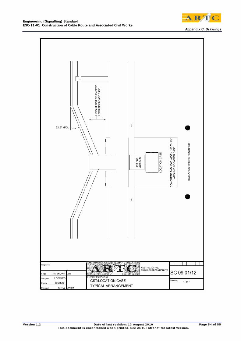
Engineering (Signalling) Standard ESC-11-01 Construction of Cable Route and Associated Civil Works Appendix C: Drawings
Version 1.2 Date of last revision: 13 August 2010 Page 54 of 55 This document is uncontrolled when printed. See ARTC Intranet for latest version.

Engineering (Signalling) Standard ESC-11-01 Construction of Cable Route and Associated Civil Works Particular Standard References
23 Particular Standard References • Section 1.1 – Scope
• Section 1.4 – Drawings
• Section 1.12 – Responsibilities
• Section 2.3 – Painting/Finish of Metal Surfaces
• Section 13.1 – Cable Installation – General
• Section 15.1 – Construction of Railway Access Road – General
• Section 15.3 - Construction
Version 1.2 Date of last revision: 13 August 2010 Page 55 of 55 This document is uncontrolled when printed. See ARTC Intranet for latest version.